EP3550672B1 - Élément de liaison - Google Patents
Élément de liaison Download PDFInfo
- Publication number
- EP3550672B1 EP3550672B1 EP18166127.3A EP18166127A EP3550672B1 EP 3550672 B1 EP3550672 B1 EP 3550672B1 EP 18166127 A EP18166127 A EP 18166127A EP 3550672 B1 EP3550672 B1 EP 3550672B1
- Authority
- EP
- European Patent Office
- Prior art keywords
- screw
- free end
- reception
- spring
- component
- Prior art date
- Legal status (The legal status is an assumption and is not a legal conclusion. Google has not performed a legal analysis and makes no representation as to the accuracy of the status listed.)
- Active
Links
Images



Classifications
-
- H—ELECTRICITY
- H01—ELECTRIC ELEMENTS
- H01R—ELECTRICALLY-CONDUCTIVE CONNECTIONS; STRUCTURAL ASSOCIATIONS OF A PLURALITY OF MUTUALLY-INSULATED ELECTRICAL CONNECTING ELEMENTS; COUPLING DEVICES; CURRENT COLLECTORS
- H01R13/00—Details of coupling devices of the kinds covered by groups H01R12/70 or H01R24/00 - H01R33/00
- H01R13/66—Structural association with built-in electrical component
- H01R13/6608—Structural association with built-in electrical component with built-in single component
- H01R13/6616—Structural association with built-in electrical component with built-in single component with resistor
-
- H—ELECTRICITY
- H01—ELECTRIC ELEMENTS
- H01R—ELECTRICALLY-CONDUCTIVE CONNECTIONS; STRUCTURAL ASSOCIATIONS OF A PLURALITY OF MUTUALLY-INSULATED ELECTRICAL CONNECTING ELEMENTS; COUPLING DEVICES; CURRENT COLLECTORS
- H01R13/00—Details of coupling devices of the kinds covered by groups H01R12/70 or H01R24/00 - H01R33/00
- H01R13/02—Contact members
- H01R13/04—Pins or blades for co-operation with sockets
-
- H—ELECTRICITY
- H01—ELECTRIC ELEMENTS
- H01R—ELECTRICALLY-CONDUCTIVE CONNECTIONS; STRUCTURAL ASSOCIATIONS OF A PLURALITY OF MUTUALLY-INSULATED ELECTRICAL CONNECTING ELEMENTS; COUPLING DEVICES; CURRENT COLLECTORS
- H01R13/00—Details of coupling devices of the kinds covered by groups H01R12/70 or H01R24/00 - H01R33/00
- H01R13/02—Contact members
- H01R13/10—Sockets for co-operation with pins or blades
-
- H—ELECTRICITY
- H01—ELECTRIC ELEMENTS
- H01R—ELECTRICALLY-CONDUCTIVE CONNECTIONS; STRUCTURAL ASSOCIATIONS OF A PLURALITY OF MUTUALLY-INSULATED ELECTRICAL CONNECTING ELEMENTS; COUPLING DEVICES; CURRENT COLLECTORS
- H01R13/00—Details of coupling devices of the kinds covered by groups H01R12/70 or H01R24/00 - H01R33/00
- H01R13/02—Contact members
- H01R13/22—Contacts for co-operating by abutting
- H01R13/24—Contacts for co-operating by abutting resilient; resiliently-mounted
- H01R13/2407—Contacts for co-operating by abutting resilient; resiliently-mounted characterized by the resilient means
- H01R13/2421—Contacts for co-operating by abutting resilient; resiliently-mounted characterized by the resilient means using coil springs
-
- H—ELECTRICITY
- H01—ELECTRIC ELEMENTS
- H01R—ELECTRICALLY-CONDUCTIVE CONNECTIONS; STRUCTURAL ASSOCIATIONS OF A PLURALITY OF MUTUALLY-INSULATED ELECTRICAL CONNECTING ELEMENTS; COUPLING DEVICES; CURRENT COLLECTORS
- H01R13/00—Details of coupling devices of the kinds covered by groups H01R12/70 or H01R24/00 - H01R33/00
- H01R13/02—Contact members
- H01R13/33—Contact members made of resilient wire
-
- H—ELECTRICITY
- H01—ELECTRIC ELEMENTS
- H01R—ELECTRICALLY-CONDUCTIVE CONNECTIONS; STRUCTURAL ASSOCIATIONS OF A PLURALITY OF MUTUALLY-INSULATED ELECTRICAL CONNECTING ELEMENTS; COUPLING DEVICES; CURRENT COLLECTORS
- H01R13/00—Details of coupling devices of the kinds covered by groups H01R12/70 or H01R24/00 - H01R33/00
- H01R13/40—Securing contact members in or to a base or case; Insulating of contact members
- H01R13/42—Securing in a demountable manner
-
- H—ELECTRICITY
- H01—ELECTRIC ELEMENTS
- H01R—ELECTRICALLY-CONDUCTIVE CONNECTIONS; STRUCTURAL ASSOCIATIONS OF A PLURALITY OF MUTUALLY-INSULATED ELECTRICAL CONNECTING ELEMENTS; COUPLING DEVICES; CURRENT COLLECTORS
- H01R31/00—Coupling parts supported only by co-operation with counterpart
- H01R31/06—Intermediate parts for linking two coupling parts, e.g. adapter
-
- H—ELECTRICITY
- H01—ELECTRIC ELEMENTS
- H01R—ELECTRICALLY-CONDUCTIVE CONNECTIONS; STRUCTURAL ASSOCIATIONS OF A PLURALITY OF MUTUALLY-INSULATED ELECTRICAL CONNECTING ELEMENTS; COUPLING DEVICES; CURRENT COLLECTORS
- H01R4/00—Electrically-conductive connections between two or more conductive members in direct contact, i.e. touching one another; Means for effecting or maintaining such contact; Electrically-conductive connections having two or more spaced connecting locations for conductors and using contact members penetrating insulation
- H01R4/28—Clamped connections, spring connections
- H01R4/30—Clamped connections, spring connections utilising a screw or nut clamping member
- H01R4/36—Conductive members located under tip of screw
-
- H—ELECTRICITY
- H01—ELECTRIC ELEMENTS
- H01R—ELECTRICALLY-CONDUCTIVE CONNECTIONS; STRUCTURAL ASSOCIATIONS OF A PLURALITY OF MUTUALLY-INSULATED ELECTRICAL CONNECTING ELEMENTS; COUPLING DEVICES; CURRENT COLLECTORS
- H01R4/00—Electrically-conductive connections between two or more conductive members in direct contact, i.e. touching one another; Means for effecting or maintaining such contact; Electrically-conductive connections having two or more spaced connecting locations for conductors and using contact members penetrating insulation
- H01R4/28—Clamped connections, spring connections
- H01R4/48—Clamped connections, spring connections utilising a spring, clip, or other resilient member
- H01R4/4854—Clamped connections, spring connections utilising a spring, clip, or other resilient member using a wire spring
- H01R4/4863—Coil spring
-
- H—ELECTRICITY
- H01—ELECTRIC ELEMENTS
- H01R—ELECTRICALLY-CONDUCTIVE CONNECTIONS; STRUCTURAL ASSOCIATIONS OF A PLURALITY OF MUTUALLY-INSULATED ELECTRICAL CONNECTING ELEMENTS; COUPLING DEVICES; CURRENT COLLECTORS
- H01R43/00—Apparatus or processes specially adapted for manufacturing, assembling, maintaining, or repairing of line connectors or current collectors or for joining electric conductors
- H01R43/20—Apparatus or processes specially adapted for manufacturing, assembling, maintaining, or repairing of line connectors or current collectors or for joining electric conductors for assembling or disassembling contact members with insulating base, case or sleeve
- H01R43/205—Apparatus or processes specially adapted for manufacturing, assembling, maintaining, or repairing of line connectors or current collectors or for joining electric conductors for assembling or disassembling contact members with insulating base, case or sleeve with a panel or printed circuit board
-
- H—ELECTRICITY
- H01—ELECTRIC ELEMENTS
- H01R—ELECTRICALLY-CONDUCTIVE CONNECTIONS; STRUCTURAL ASSOCIATIONS OF A PLURALITY OF MUTUALLY-INSULATED ELECTRICAL CONNECTING ELEMENTS; COUPLING DEVICES; CURRENT COLLECTORS
- H01R12/00—Structural associations of a plurality of mutually-insulated electrical connecting elements, specially adapted for printed circuits, e.g. printed circuit boards [PCB], flat or ribbon cables, or like generally planar structures, e.g. terminal strips, terminal blocks; Coupling devices specially adapted for printed circuits, flat or ribbon cables, or like generally planar structures; Terminals specially adapted for contact with, or insertion into, printed circuits, flat or ribbon cables, or like generally planar structures
- H01R12/50—Fixed connections
- H01R12/51—Fixed connections for rigid printed circuits or like structures
- H01R12/53—Fixed connections for rigid printed circuits or like structures connecting to cables except for flat or ribbon cables
-
- H—ELECTRICITY
- H01—ELECTRIC ELEMENTS
- H01R—ELECTRICALLY-CONDUCTIVE CONNECTIONS; STRUCTURAL ASSOCIATIONS OF A PLURALITY OF MUTUALLY-INSULATED ELECTRICAL CONNECTING ELEMENTS; COUPLING DEVICES; CURRENT COLLECTORS
- H01R13/00—Details of coupling devices of the kinds covered by groups H01R12/70 or H01R24/00 - H01R33/00
- H01R13/62—Means for facilitating engagement or disengagement of coupling parts or for holding them in engagement
- H01R13/629—Additional means for facilitating engagement or disengagement of coupling parts, e.g. aligning or guiding means, levers, gas pressure electrical locking indicators, manufacturing tolerances
- H01R13/631—Additional means for facilitating engagement or disengagement of coupling parts, e.g. aligning or guiding means, levers, gas pressure electrical locking indicators, manufacturing tolerances for engagement only
- H01R13/6315—Additional means for facilitating engagement or disengagement of coupling parts, e.g. aligning or guiding means, levers, gas pressure electrical locking indicators, manufacturing tolerances for engagement only allowing relative movement between coupling parts, e.g. floating connection
Definitions
- the present invention relates to a connecting element, in particular an electrical connecting element.
- Connection elements are known from the prior art which comprise, for example, a pin which can be detachably inserted into a corresponding pin receptacle. When using such connecting elements, it is very important to adhere to the manufacturing and assembly tolerances, since otherwise the connecting element can no longer be inserted into a corresponding socket.
- US 7,677,901 B1 describes a contact element which consists of a strip-shaped plunger and a spiral spring, a lower part of the plunger being inserted into the spiral spring, and a middle part of the plunger resting on an upper end of the spiral spring, so that the plunger is separated from the spiral spring in the longitudinal direction of the contact element is held resiliently.
- GB 2539702 A describes a connecting element which has a spiral spring between two end parts so that the two end parts are flexibly connected to one another, whereby the connecting element can be bent in all three spatial directions, stretched and compressed along its longitudinal axis and rotated about its longitudinal axis.
- One object of the present invention is to provide a connecting element which can still be safely inserted into a corresponding socket even with larger manufacturing and assembly tolerances.
- a connecting element according to the invention comprises a screw-in element and a contact element, wherein the Screw-in element is designed in the form of a pin and extends along a longitudinal axis. At its first free end, the screw-in element comprises a thread and at its second free end it has an entrainment profile and a receptacle.
- the contact element is arranged with its first free end in the receptacle and at its second free end it comprises a connecting pin which protrudes beyond the screw-in element in the direction of the longitudinal axis.
- the contact element comprises a spring which is arranged between the screw-in element and the connecting pin. Manufacturing-related inaccuracies can be compensated for by the spring. That is, the screw-in elements do not have to be aligned exactly with the corresponding sockets so that the contact elements can be inserted into the sockets.
- the driving profile of the screw-in element comprises an inner profile, for example a hexagon socket.
- slotted, cross or Torx profiles can also be provided.
- the receptacle of the screw-in element comprises a peripheral recess, the first free end of the contact element comprising the spring and being arranged with the spring in the peripheral recess.
- the cross section of the peripheral recess can be the same as the cross section of the corresponding spring.
- the cross-sections can be designed differently.
- the peripheral recess can be a spiral with an angular or round cross section.
- the spring can also be a spiral spring with a round or angular cross-section.
- the peripheral recess is identical to the thread and extends over the entire length of the screw-in element.
- the peripheral recess and the thread can be designed differently.
- the spiral of the peripheral recess can have a larger cross section than that of the thread.
- the entrainment profile of the screw-in element comprises an outer profile, the screw-in element comprising a fastening pin with a peripheral receptacle at the second free end and the first free end of the contact element comprising the spring and being arranged with the spring in the peripheral receptacle.
- the fastening pin is formed in one piece with the screw-in element.
- the fastening pin is arranged in a central recess in the screw-in element.
- the driving profile of the screw-in element comprises an outer profile, the screw-in element comprising a central receptacle at the second free end, the first free end of the contact element comprising the spring and a fastening pin and being arranged with the fastening pin in the central receptacle.
- the contour of the contact element in the region of the receptacle is essentially congruent with that of the receptacle and represents a precisely fitting connection.
- the connecting pin extends essentially along the longitudinal axis, in the extension of the longitudinal center axis of the screw-in element.
- the connecting pin can be arranged offset to the longitudinal axis and extend essentially in the direction of the longitudinal axis.
- the connecting pin can also be arranged tangentially to a lateral surface of the screw-in element.
- the screw-in element and the contact element are formed from an electrically conductive material and are electrically operatively connected to one another.
- the mentioned embodiments of the connecting element can be used in any combination, provided that they do not contradict one another.
- a connection arrangement comprises a first component, the first component comprising at least one threaded bore, a connecting element according to one of the previously described embodiments being screwed into at least one of the threaded bores.
- connection arrangement further comprises at least one second component, each second component comprising at least one socket, the connecting pin of the at least one connection element being arranged in the at least one socket in the intended use position.
- the socket is designed in such a way that connection elements of the first component through the connection element and the corresponding socket with Connection elements of the second component can be effectively connected electrically.
- an end face on the first free end of the screw-in element of the respective connection element is in electrical contact with the corresponding connection element of the first component.
- At least one of the threaded bores comprises a countersink into which the contact element can be at least partially inserted.
- the threaded hole can be provided without countersinking.
- connection arrangement can be used in any combination provided they do not contradict one another.
- the Figure 1 shows a perspective view of an embodiment of a connecting element according to the invention.
- the connecting element comprises a screw-in element 1 and a contact element 2 arranged on the screw-in element 1.
- the screw-in element 1 is pin-shaped and extends along a longitudinal axis L.
- a thread 100 is provided on a first free end 10 of the screw-in element 1 and a thread 100 is provided on a second free end 11 a driving profile 110 in the form of a hexagon socket.
- the contact element 2 comprises a spring 200 at a first free end 20 and a connecting pin 210 at a second free end
- the contact element 2 is arranged with the spring 200 at the second free end 11 of the screw-in element 1.
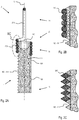
- the Figure 2A shows a schematic sectional view through the longitudinal axis L of an embodiment of a connecting element according to the invention, a first embodiment of the screw-in element 1 being shown on the right-hand side and a second embodiment on the left-hand side.
- the first embodiment of the screw-in element 1 comprises on its lateral surface 101 a thread 100 which extends from the first free end 10 and a receptacle 111 which extends from the second free end 11.
- the receptacle 111 is a spiral recess with a circular cross section.
- the outer contour of the receptacle 111 is congruent with the inner contour of the spring 200 of the contact element 2.
- the thread 100 is finer than the receptacle 111.
- An inner profile 110 is provided at the second free end.
- the thread 100 is identical to the receptacle 111 and extends from the first free end 10 to the second free end 11.
- the outer contour of the thread 100 or the receptacle 111 is congruent with the inner contour of the spring 200 of the contact element 2.
- Figure 2B shows a combination of a thread 100 or a receptacle 111 with the shape of a pointed thread and a spring 200 with a spring wire with a circular cross section.
- the Figure 2C shows a combination of a pointed thread 100 with a spring 200 with a spring wire with a trapezoidal cross-section.
- all known types of thread such as, for example, trapezoidal thread, round thread or flat thread, are possible as the receptacle 100.
- Springs 200 with spring wires with round, oval or polygonal cross-sections can also be used.
- the Figure 3 shows a schematic sectional view of an alternative embodiment of a connecting element according to the invention.
- an outer profile 112 is provided as a driving profile, for example a hexagonal profile. Adjacent to this is a fastening pin 113 with a peripheral receptacle 114, the fastening pin 113 being formed together in one piece with the screw-in element 1.
- the peripheral receptacle 114 is a spiral recess.
- the spring 200 of the contact element 2 is arranged in the peripheral receptacle 114.
- the outer contour of the receptacle 114 is congruent with the inner contour of the spring 200.
- the Figure 4 shows a schematic sectional view of an alternative embodiment of a connecting element according to the invention.
- the pin 113 is arranged in a central receptacle 115, which is formed on the front side on the second free end 11 of the screw-in element 1.
- the central receptacle is a recess in the form of a bore.
- the pin 113 in turn comprises the peripheral receptacle 114 and the spring 200 is arranged in the peripheral receptacle 114.
- the Figure 5 shows a schematic sectional view of an alternative embodiment of a connecting element according to the invention.
- the screw-in element 1 comprises a peripheral driver profile 112 at the second free end 11 and a central receptacle 115 arranged at the end.
- the contact element 2 comprises the spring 200 and a fastening pin 201 at the first free end 20.
- the contact element 2 is with the fastening pin 201 in the central receptacle 115 of the screw-in element 1 is arranged.
- FIGS. 6A-D show different embodiments of connecting pins 210 of connecting elements 2 according to the invention.
- the Figure 6A shows a simple straight pin with a face at the free end.
- the free end can be rounded.
- the Figure 6B shows a simply bent pin, the two legs adjoining the arch run parallel and in contact with one another.
- the Figure 6C shows a U-shaped pin, wherein the two legs adjoining the middle part run parallel and at a distance from one another and wherein the middle part is oriented essentially perpendicular to the two legs.
- the Figure 6D shows a U-shaped pin, the two legs adjoining the middle part from the middle part converge away and wherein the middle part is oriented obliquely, ie not at right angles to the two legs.
- the Figure 7 shows a schematic sectional view through a connection arrangement according to the invention.
- the arrangement comprises a first component 3, which is connected to a second component 4 by connecting elements 1, 2.
- the first component 3 comprises a first connection element 5, which is fixed in the first component 3 with fastening elements 7.
- a toothed rack is shown as the connection element 5, which can be, for example, the vertically displaceable Z-axis of a manipulator.
- the rack 5 is fixed in the housing of the first component 3 with a threaded pin 7.
- the threaded pin 7 is screwed into a threaded bore 31 in the housing of the first component 3.
- One connecting element 1, 2 is screwed into a further threaded bore 30, the end face of the screw-in element 1 being in electrically conductive contact with the toothed rack 5.
- the further threaded bore 30 comprises, on its side directed towards the second component 4, a countersink 300 with a larger diameter than the section of the further bore with the thread.
- the spring 200 of the contact element 2 is partially arranged in the depression 300.
- the spring 200 and the connecting pin 210 protrude from the first component 3.
- a second connection element 6 is fixed separately from the first connection element 5 in the housing of the first component 3 with a threaded pin 7 with a hexagon socket.
- a connecting element 1, 2 according to the invention is in electrical contact with the second connection element 6.
- the second component 4 comprises sockets 40 into which the Connecting pins 210 of the contact element 2 can be inserted in order to produce an electrical contact.
- the second component 4 further comprises connection elements 41, which are electrically connected to the sockets.
- the first connection element 5 of the first component 3 can be electrically connected to the second connection element 6 of the first component 3 by the connection elements 1, 2, the sockets 40 and the connection elements 41 of the second component 4.
- Screw-in element 21 second free end 10 first free end 210 Connecting pin 100 thread 3 first component 101 Outer surface 30th Threaded hole 11 second free end 300 Lowering 110 centric driving profile 31 Threaded hole 4th second component 111 peripheral admission 40 Rifle 112 peripheral driving profile 41 Connection element 5 first 113 pen Connection element 114 peripheral admission 6th second 115 centric recording Connection element 2 Contact element 7th Fastener 20th first free end 200 feather L. Longitudinal axis 201 Fixing pin
Landscapes
- Engineering & Computer Science (AREA)
- Manufacturing & Machinery (AREA)
- Connections By Means Of Piercing Elements, Nuts, Or Screws (AREA)
- Details Of Connecting Devices For Male And Female Coupling (AREA)
- Connections Arranged To Contact A Plurality Of Conductors (AREA)
- Measuring Leads Or Probes (AREA)
Claims (14)
- Élément de liaison comprenant un élément fileté (1) et un élément de contact (2), l'élément fileté (1) étant réalisé en forme de tige le long d'un axe longitudinal (L), comprenant au niveau de sa première extrémité libre (10) un filetage (100) et au niveau de sa deuxième extrémité libre (11) un profil d'entraînement (110, 112) et un logement (111, 114, 115), l'élément de contact (2) étant agencé avec sa première extrémité libre (20) dans le logement (111, 114, 115) et comprenant au niveau de sa deuxième extrémité libre (21) une broche de liaison (210) qui fait saillie au-dessus de l'élément fileté (1) dans la direction de l'axe longitudinal (L), caractérisé en ce que l'élément de contact (2) comprend un ressort (200) qui est agencé dans la zone de la première extrémité libre (20) de l'élément de contact (2).
- Élément de liaison selon la revendication 1, dans lequel le profil d'entraînement de l'élément fileté (1) comprend un profil intérieur (110), le logement de l'élément fileté (1) comprenant un logement périphérique (111), et la première extrémité libre (20) de l'élément de contact (2) comprenant le ressort (200) et étant agencée avec le ressort (200) dans le logement périphérique (111).
- Élément de liaison selon la revendication 2, dans lequel le logement périphérique (111) est identique au filetage (100) et s'étend sur toute la longueur de l'élément fileté (1).
- Élément de liaison selon la revendication 1, dans lequel le profil d'entraînement de l'élément fileté (1) comprend un profil extérieur (112), l'élément fileté (1) comprenant au niveau de la deuxième extrémité libre (11) une broche de fixation (113) avec un logement périphérique (114), et la première extrémité libre (20) de l'élément de contact (2) comprenant le ressort (200) et étant agencée avec le ressort (200) dans le logement périphérique (114).
- Élément de liaison selon la revendication 4, dans lequel la broche de fixation (113) est réalisée d'un seul tenant avec l'élément fileté (1).
- Élément de liaison selon la revendication 4, dans lequel la broche de fixation (113) est agencée dans un logement central (115) dans l'élément fileté (1).
- Élément de liaison selon la revendication 1, dans lequel le profil d'entraînement de l'élément fileté (1) comprend un profil extérieur (112), l'élément fileté (1) comprenant au niveau de la deuxième extrémité libre (11) un logement central (115), la première extrémité libre (20) de l'élément de contact (2) comprenant le ressort (200) et une broche de fixation (201) et étant agencée avec la broche de fixation (201) dans le logement central (115).
- Élément de liaison selon l'une des revendications précédentes, dans lequel le contour de l'élément de contact (2) est réalisé, dans la zone du logement (111, 114, 115), sensiblement en concordance avec ce dernier et constitue une connexion parfaite.
- Élément de liaison selon l'une des revendications précédentes, dans lequel l'élément fileté (1) et l'élément de contact (2) sont réalisés dans un matériau électriquement conducteur et sont raccordés électriquement entre eux.
- Dispositif de liaison comprenant un premier composant (3), dans lequel le premier composant (3) comprend au moins un alésage taraudé (30, 31), caractérisé en ce qu'il est vissé dans au moins un des alésages taraudés (30) un élément de liaison selon l'une des revendications 1 à 9.
- Dispositif de liaison selon la revendication 10, comprenant en outre au moins un deuxième composant (4), le deuxième composant (4) comprenant au moins une douille (40), la broche de liaison (210) du au moins un élément de liaison étant agencée dans la au moins une douille (40) dans la position d'utilisation conforme.
- Dispositif de liaison selon la revendication 10 ou 11, dans lequel la douille (40) est réalisée de telle sorte que les éléments de raccordement (5, 6) du premier composant (3) peuvent être reliés électriquement aux éléments de raccordement (41) du deuxième composant (4) par l'élément de liaison et la douille (40).
- Dispositif de liaison selon la revendication 12, dans lequel une face frontale au niveau de la première extrémité libre (10) de l'élément fileté (1) de l'élément de liaison correspondant est en contact électrique avec l'élément de raccordement correspondant (5, 6) du premier composant (3).
- Dispositif de liaison selon l'une des revendications 10 à 13, dans lequel au moins un des alésages taraudés (30) comprend un enfoncement (300) dans lequel l'élément de contact (2) peut être introduit au moins partiellement.
Priority Applications (3)
| Application Number | Priority Date | Filing Date | Title |
|---|---|---|---|
| EP18166127.3A EP3550672B1 (fr) | 2018-04-06 | 2018-04-06 | Élément de liaison |
| US16/373,073 US10530087B2 (en) | 2018-04-06 | 2019-04-02 | Connecting element |
| CN201910271011.6A CN110350374B (zh) | 2018-04-06 | 2019-04-04 | 连接元件和连接组件 |
Applications Claiming Priority (1)
| Application Number | Priority Date | Filing Date | Title |
|---|---|---|---|
| EP18166127.3A EP3550672B1 (fr) | 2018-04-06 | 2018-04-06 | Élément de liaison |
Publications (2)
| Publication Number | Publication Date |
|---|---|
| EP3550672A1 EP3550672A1 (fr) | 2019-10-09 |
| EP3550672B1 true EP3550672B1 (fr) | 2021-08-04 |
Family
ID=61913010
Family Applications (1)
| Application Number | Title | Priority Date | Filing Date |
|---|---|---|---|
| EP18166127.3A Active EP3550672B1 (fr) | 2018-04-06 | 2018-04-06 | Élément de liaison |
Country Status (3)
| Country | Link |
|---|---|
| US (1) | US10530087B2 (fr) |
| EP (1) | EP3550672B1 (fr) |
| CN (1) | CN110350374B (fr) |
Family Cites Families (25)
| Publication number | Priority date | Publication date | Assignee | Title |
|---|---|---|---|---|
| US3058083A (en) * | 1960-01-29 | 1962-10-09 | Burroughs Corp | Electrical connector |
| US3503033A (en) * | 1967-12-12 | 1970-03-24 | Gen Electric | Coil spring connector |
| US4192567A (en) * | 1978-05-08 | 1980-03-11 | William Gomolka | Electrical connector |
| US5038467A (en) * | 1989-11-09 | 1991-08-13 | Advanced Interconnections Corporation | Apparatus and method for installation of multi-pin components on circuit boards |
| US6155846A (en) * | 2000-01-03 | 2000-12-05 | Motorola, Inc. | Electrical contactor assembly |
| US6565395B1 (en) * | 2001-12-21 | 2003-05-20 | Northrop Grumman Corporation | Electrical connection to a coil spring through a local interference fit for connection to a vibratory rotation sensor and method of forming the same |
| JP2004007156A (ja) * | 2002-05-31 | 2004-01-08 | Matsushita Electric Ind Co Ltd | コンデンサマイクロホン |
| AT9304U1 (de) * | 2006-06-13 | 2007-07-15 | Pc Electric Gmbh | Leiteranschlussklemme und elektrische steckvorrichtung |
| US7796397B2 (en) * | 2006-08-23 | 2010-09-14 | Panasonic Corporation | Electronic components assembly and method for producing same |
| JP2011507162A (ja) * | 2007-12-06 | 2011-03-03 | バル・シール・エンジニアリング | インラインコネクタ |
| JP2009146820A (ja) * | 2007-12-17 | 2009-07-02 | Hosiden Corp | コンタクト及び接続装置 |
| US20090259264A1 (en) * | 2008-04-14 | 2009-10-15 | Alfred E. Mann Foundation For Scientific Research | Surgically implantable wire connector |
| CN201436716U (zh) * | 2008-10-16 | 2010-04-07 | 上海华伦仪表电子有限公司 | 一种大电流连接器 |
| JP4900843B2 (ja) * | 2008-12-26 | 2012-03-21 | 山一電機株式会社 | 半導体装置用電気接続装置及びそれに使用されるコンタクト |
| DE202009003592U1 (de) * | 2009-03-13 | 2009-05-20 | Rosenberger Hochfrequenztechnik Gmbh & Co. Kg | Abdichtung eines gefederten Kontaktstiftes |
| US20100267291A1 (en) * | 2009-04-20 | 2010-10-21 | Scott Chabineau-Lovgren | Swaging process for improved compliant contact electrical test performance |
| US20110059661A1 (en) * | 2009-09-08 | 2011-03-10 | Denso Corporation | Electrical connector assembly for connecting printed circuit board and electrical component, and electric device |
| CN101908695B (zh) * | 2010-06-21 | 2011-12-21 | 贵州航天电器股份有限公司 | 一种气电混装分离连接器 |
| TWI424624B (zh) * | 2011-09-05 | 2014-01-21 | Frank Hayama | Conductive element and its preparation method |
| CN106936044B (zh) * | 2013-02-15 | 2019-06-21 | 史陶比尔电子连接器股份公司 | 用于接触母线的装置 |
| CH708837A1 (de) * | 2013-11-14 | 2015-05-15 | Kistler Holding Ag | Piezoelektrischer Kraftsensor mit lösbarer elektrischer Verbindung zwischen Elektrode und Kontaktpin. |
| DE102014211003A1 (de) * | 2014-06-10 | 2015-12-17 | Robert Bosch Gmbh | Anordnung zur elektrischen Kontaktierung eines ersten Kontaktpartners und eines zweiten Kontaktpartners |
| US9748678B2 (en) * | 2015-03-31 | 2017-08-29 | Sensata Technologies, Inc. | Connectivity in an assembly |
| GB2539702A (en) * | 2015-06-25 | 2016-12-28 | Alstom Technology Ltd | Power converter sub-module |
| GB2546081B (en) * | 2016-01-06 | 2019-08-14 | Amphenol Ltd | Pin for adapting electrical connectors, and a kit of parts inlcuding same |
-
2018
- 2018-04-06 EP EP18166127.3A patent/EP3550672B1/fr active Active
-
2019
- 2019-04-02 US US16/373,073 patent/US10530087B2/en active Active
- 2019-04-04 CN CN201910271011.6A patent/CN110350374B/zh active Active
Also Published As
| Publication number | Publication date |
|---|---|
| CN110350374B (zh) | 2024-05-28 |
| US10530087B2 (en) | 2020-01-07 |
| US20190312370A1 (en) | 2019-10-10 |
| CN110350374A (zh) | 2019-10-18 |
| EP3550672A1 (fr) | 2019-10-09 |
Similar Documents
| Publication | Publication Date | Title |
|---|---|---|
| DE112012007184B4 (de) | Wellenendadapter und Kugelrollspindelaufbau | |
| EP3164911B1 (fr) | Fiche de raccordement | |
| DE102014118726B4 (de) | Kopplungsanordnung mit einer Fließbohrschraube | |
| DE102009015542A1 (de) | Bidirektionale Kabelschuhverbindung und Verfahren | |
| DE102008058204A1 (de) | Steckbuchse | |
| EP2079275A1 (fr) | Champ de cuisson à induction doté d'un dispositif de fixation destiné à la fixation d'un support à induction sur un cadre de montage | |
| EP1443251A2 (fr) | Dispositif de bride | |
| DE202011004481U1 (de) | Temperatursensor mit Halteplatte | |
| DE2239476A1 (de) | Elektrischer verbinder und verfahren zur herstellung einer verbindung | |
| EP3550672B1 (fr) | Élément de liaison | |
| DE102025112026A1 (de) | Eine Mehrkantschraube sowie ein Verfahren zur Verwendung einer solchen Mehrkantschraube | |
| DE2323612A1 (de) | Elektrisches verbindungsglied | |
| DE102011084900A1 (de) | Anbindungsanordnung sowie Halteelement zum Anschluss einer elektrischen Leitung an einen Bauteilabschnitt | |
| EP3828426B1 (fr) | Élément de fixation pour tubes à plusieurs bordures | |
| DE102009020378A1 (de) | Schraubbares Anschlusselement | |
| DE20201046U1 (de) | Sicherungsvorrichtung für ein Verriegelungselement für CPU-Wärmeableitelemente | |
| DE202008009589U1 (de) | Beleuchtungseinheit | |
| EP2590493A2 (fr) | Convertisseur de fréquence | |
| DE19754527C2 (de) | Klinkenbuchse | |
| EP1416588A1 (fr) | Connecteur de câble | |
| DE19945310A1 (de) | Steckverbinder | |
| DE102005061827B4 (de) | Computergehäuse | |
| DE202015104842U1 (de) | Gewindeverbindung und Bohrgestänge mit Gewindeverbindung | |
| DE4293421C2 (de) | Steckervorrichtung für ein Kabel | |
| EP0163892B1 (fr) | Douille pour lampe à incandescence |
Legal Events
| Date | Code | Title | Description |
|---|---|---|---|
| PUAI | Public reference made under article 153(3) epc to a published international application that has entered the european phase |
Free format text: ORIGINAL CODE: 0009012 |
|
| STAA | Information on the status of an ep patent application or granted ep patent |
Free format text: STATUS: THE APPLICATION HAS BEEN PUBLISHED |
|
| AK | Designated contracting states |
Kind code of ref document: A1 Designated state(s): AL AT BE BG CH CY CZ DE DK EE ES FI FR GB GR HR HU IE IS IT LI LT LU LV MC MK MT NL NO PL PT RO RS SE SI SK SM TR |
|
| AX | Request for extension of the european patent |
Extension state: BA ME |
|
| STAA | Information on the status of an ep patent application or granted ep patent |
Free format text: STATUS: REQUEST FOR EXAMINATION WAS MADE |
|
| 17P | Request for examination filed |
Effective date: 20200403 |
|
| RBV | Designated contracting states (corrected) |
Designated state(s): AL AT BE BG CH CY CZ DE DK EE ES FI FR GB GR HR HU IE IS IT LI LT LU LV MC MK MT NL NO PL PT RO RS SE SI SK SM TR |
|
| GRAP | Despatch of communication of intention to grant a patent |
Free format text: ORIGINAL CODE: EPIDOSNIGR1 |
|
| STAA | Information on the status of an ep patent application or granted ep patent |
Free format text: STATUS: GRANT OF PATENT IS INTENDED |
|
| RIC1 | Information provided on ipc code assigned before grant |
Ipc: H01R 4/36 20060101ALI20210208BHEP Ipc: H01R 13/631 20060101ALN20210208BHEP Ipc: H01R 12/53 20110101ALN20210208BHEP Ipc: H01R 13/24 20060101AFI20210208BHEP |
|
| RIC1 | Information provided on ipc code assigned before grant |
Ipc: H01R 13/631 20060101ALN20210215BHEP Ipc: H01R 4/36 20060101ALI20210215BHEP Ipc: H01R 12/53 20110101ALN20210215BHEP Ipc: H01R 13/24 20060101AFI20210215BHEP |
|
| RIC1 | Information provided on ipc code assigned before grant |
Ipc: H01R 12/53 20110101ALN20210225BHEP Ipc: H01R 13/631 20060101ALN20210225BHEP Ipc: H01R 13/24 20060101AFI20210225BHEP Ipc: H01R 4/36 20060101ALI20210225BHEP |
|
| INTG | Intention to grant announced |
Effective date: 20210316 |
|
| GRAS | Grant fee paid |
Free format text: ORIGINAL CODE: EPIDOSNIGR3 |
|
| GRAA | (expected) grant |
Free format text: ORIGINAL CODE: 0009210 |
|
| STAA | Information on the status of an ep patent application or granted ep patent |
Free format text: STATUS: THE PATENT HAS BEEN GRANTED |
|
| AK | Designated contracting states |
Kind code of ref document: B1 Designated state(s): AL AT BE BG CH CY CZ DE DK EE ES FI FR GB GR HR HU IE IS IT LI LT LU LV MC MK MT NL NO PL PT RO RS SE SI SK SM TR |
|
| REG | Reference to a national code |
Ref country code: GB Ref legal event code: FG4D Free format text: NOT ENGLISH |
|
| REG | Reference to a national code |
Ref country code: AT Ref legal event code: REF Ref document number: 1417963 Country of ref document: AT Kind code of ref document: T Effective date: 20210815 |
|
| REG | Reference to a national code |
Ref country code: CH Ref legal event code: EP |
|
| REG | Reference to a national code |
Ref country code: DE Ref legal event code: R096 Ref document number: 502018006391 Country of ref document: DE |
|
| REG | Reference to a national code |
Ref country code: IE Ref legal event code: FG4D Free format text: LANGUAGE OF EP DOCUMENT: GERMAN |
|
| REG | Reference to a national code |
Ref country code: LT Ref legal event code: MG9D |
|
| REG | Reference to a national code |
Ref country code: NL Ref legal event code: MP Effective date: 20210804 |
|
| PG25 | Lapsed in a contracting state [announced via postgrant information from national office to epo] |
Ref country code: SE Free format text: LAPSE BECAUSE OF FAILURE TO SUBMIT A TRANSLATION OF THE DESCRIPTION OR TO PAY THE FEE WITHIN THE PRESCRIBED TIME-LIMIT Effective date: 20210804 Ref country code: RS Free format text: LAPSE BECAUSE OF FAILURE TO SUBMIT A TRANSLATION OF THE DESCRIPTION OR TO PAY THE FEE WITHIN THE PRESCRIBED TIME-LIMIT Effective date: 20210804 Ref country code: HR Free format text: LAPSE BECAUSE OF FAILURE TO SUBMIT A TRANSLATION OF THE DESCRIPTION OR TO PAY THE FEE WITHIN THE PRESCRIBED TIME-LIMIT Effective date: 20210804 Ref country code: FI Free format text: LAPSE BECAUSE OF FAILURE TO SUBMIT A TRANSLATION OF THE DESCRIPTION OR TO PAY THE FEE WITHIN THE PRESCRIBED TIME-LIMIT Effective date: 20210804 Ref country code: ES Free format text: LAPSE BECAUSE OF FAILURE TO SUBMIT A TRANSLATION OF THE DESCRIPTION OR TO PAY THE FEE WITHIN THE PRESCRIBED TIME-LIMIT Effective date: 20210804 Ref country code: NO Free format text: LAPSE BECAUSE OF FAILURE TO SUBMIT A TRANSLATION OF THE DESCRIPTION OR TO PAY THE FEE WITHIN THE PRESCRIBED TIME-LIMIT Effective date: 20211104 Ref country code: PT Free format text: LAPSE BECAUSE OF FAILURE TO SUBMIT A TRANSLATION OF THE DESCRIPTION OR TO PAY THE FEE WITHIN THE PRESCRIBED TIME-LIMIT Effective date: 20211206 Ref country code: BG Free format text: LAPSE BECAUSE OF FAILURE TO SUBMIT A TRANSLATION OF THE DESCRIPTION OR TO PAY THE FEE WITHIN THE PRESCRIBED TIME-LIMIT Effective date: 20211104 Ref country code: LT Free format text: LAPSE BECAUSE OF FAILURE TO SUBMIT A TRANSLATION OF THE DESCRIPTION OR TO PAY THE FEE WITHIN THE PRESCRIBED TIME-LIMIT Effective date: 20210804 |
|
| PG25 | Lapsed in a contracting state [announced via postgrant information from national office to epo] |
Ref country code: PL Free format text: LAPSE BECAUSE OF FAILURE TO SUBMIT A TRANSLATION OF THE DESCRIPTION OR TO PAY THE FEE WITHIN THE PRESCRIBED TIME-LIMIT Effective date: 20210804 Ref country code: LV Free format text: LAPSE BECAUSE OF FAILURE TO SUBMIT A TRANSLATION OF THE DESCRIPTION OR TO PAY THE FEE WITHIN THE PRESCRIBED TIME-LIMIT Effective date: 20210804 Ref country code: GR Free format text: LAPSE BECAUSE OF FAILURE TO SUBMIT A TRANSLATION OF THE DESCRIPTION OR TO PAY THE FEE WITHIN THE PRESCRIBED TIME-LIMIT Effective date: 20211105 |
|
| PG25 | Lapsed in a contracting state [announced via postgrant information from national office to epo] |
Ref country code: NL Free format text: LAPSE BECAUSE OF FAILURE TO SUBMIT A TRANSLATION OF THE DESCRIPTION OR TO PAY THE FEE WITHIN THE PRESCRIBED TIME-LIMIT Effective date: 20210804 |
|
| PG25 | Lapsed in a contracting state [announced via postgrant information from national office to epo] |
Ref country code: DK Free format text: LAPSE BECAUSE OF FAILURE TO SUBMIT A TRANSLATION OF THE DESCRIPTION OR TO PAY THE FEE WITHIN THE PRESCRIBED TIME-LIMIT Effective date: 20210804 |
|
| REG | Reference to a national code |
Ref country code: DE Ref legal event code: R097 Ref document number: 502018006391 Country of ref document: DE |
|
| PG25 | Lapsed in a contracting state [announced via postgrant information from national office to epo] |
Ref country code: SM Free format text: LAPSE BECAUSE OF FAILURE TO SUBMIT A TRANSLATION OF THE DESCRIPTION OR TO PAY THE FEE WITHIN THE PRESCRIBED TIME-LIMIT Effective date: 20210804 Ref country code: SK Free format text: LAPSE BECAUSE OF FAILURE TO SUBMIT A TRANSLATION OF THE DESCRIPTION OR TO PAY THE FEE WITHIN THE PRESCRIBED TIME-LIMIT Effective date: 20210804 Ref country code: RO Free format text: LAPSE BECAUSE OF FAILURE TO SUBMIT A TRANSLATION OF THE DESCRIPTION OR TO PAY THE FEE WITHIN THE PRESCRIBED TIME-LIMIT Effective date: 20210804 Ref country code: EE Free format text: LAPSE BECAUSE OF FAILURE TO SUBMIT A TRANSLATION OF THE DESCRIPTION OR TO PAY THE FEE WITHIN THE PRESCRIBED TIME-LIMIT Effective date: 20210804 Ref country code: CZ Free format text: LAPSE BECAUSE OF FAILURE TO SUBMIT A TRANSLATION OF THE DESCRIPTION OR TO PAY THE FEE WITHIN THE PRESCRIBED TIME-LIMIT Effective date: 20210804 Ref country code: AL Free format text: LAPSE BECAUSE OF FAILURE TO SUBMIT A TRANSLATION OF THE DESCRIPTION OR TO PAY THE FEE WITHIN THE PRESCRIBED TIME-LIMIT Effective date: 20210804 |
|
| PLBE | No opposition filed within time limit |
Free format text: ORIGINAL CODE: 0009261 |
|
| STAA | Information on the status of an ep patent application or granted ep patent |
Free format text: STATUS: NO OPPOSITION FILED WITHIN TIME LIMIT |
|
| 26N | No opposition filed |
Effective date: 20220506 |
|
| PG25 | Lapsed in a contracting state [announced via postgrant information from national office to epo] |
Ref country code: IT Free format text: LAPSE BECAUSE OF FAILURE TO SUBMIT A TRANSLATION OF THE DESCRIPTION OR TO PAY THE FEE WITHIN THE PRESCRIBED TIME-LIMIT Effective date: 20210804 |
|
| PG25 | Lapsed in a contracting state [announced via postgrant information from national office to epo] |
Ref country code: SI Free format text: LAPSE BECAUSE OF FAILURE TO SUBMIT A TRANSLATION OF THE DESCRIPTION OR TO PAY THE FEE WITHIN THE PRESCRIBED TIME-LIMIT Effective date: 20210804 |
|
| REG | Reference to a national code |
Ref country code: BE Ref legal event code: MM Effective date: 20220430 |
|
| PG25 | Lapsed in a contracting state [announced via postgrant information from national office to epo] |
Ref country code: MC Free format text: LAPSE BECAUSE OF FAILURE TO SUBMIT A TRANSLATION OF THE DESCRIPTION OR TO PAY THE FEE WITHIN THE PRESCRIBED TIME-LIMIT Effective date: 20210804 Ref country code: LU Free format text: LAPSE BECAUSE OF NON-PAYMENT OF DUE FEES Effective date: 20220406 |
|
| PG25 | Lapsed in a contracting state [announced via postgrant information from national office to epo] |
Ref country code: BE Free format text: LAPSE BECAUSE OF NON-PAYMENT OF DUE FEES Effective date: 20220430 |
|
| PG25 | Lapsed in a contracting state [announced via postgrant information from national office to epo] |
Ref country code: IE Free format text: LAPSE BECAUSE OF NON-PAYMENT OF DUE FEES Effective date: 20220406 |
|
| P01 | Opt-out of the competence of the unified patent court (upc) registered |
Effective date: 20230522 |
|
| PG25 | Lapsed in a contracting state [announced via postgrant information from national office to epo] |
Ref country code: HU Free format text: LAPSE BECAUSE OF FAILURE TO SUBMIT A TRANSLATION OF THE DESCRIPTION OR TO PAY THE FEE WITHIN THE PRESCRIBED TIME-LIMIT; INVALID AB INITIO Effective date: 20180406 |
|
| PG25 | Lapsed in a contracting state [announced via postgrant information from national office to epo] |
Ref country code: MK Free format text: LAPSE BECAUSE OF FAILURE TO SUBMIT A TRANSLATION OF THE DESCRIPTION OR TO PAY THE FEE WITHIN THE PRESCRIBED TIME-LIMIT Effective date: 20210804 Ref country code: CY Free format text: LAPSE BECAUSE OF FAILURE TO SUBMIT A TRANSLATION OF THE DESCRIPTION OR TO PAY THE FEE WITHIN THE PRESCRIBED TIME-LIMIT Effective date: 20210804 |
|
| REG | Reference to a national code |
Ref country code: AT Ref legal event code: MM01 Ref document number: 1417963 Country of ref document: AT Kind code of ref document: T Effective date: 20230406 |
|
| PG25 | Lapsed in a contracting state [announced via postgrant information from national office to epo] |
Ref country code: AT Free format text: LAPSE BECAUSE OF NON-PAYMENT OF DUE FEES Effective date: 20230406 |
|
| PG25 | Lapsed in a contracting state [announced via postgrant information from national office to epo] |
Ref country code: AT Free format text: LAPSE BECAUSE OF NON-PAYMENT OF DUE FEES Effective date: 20230406 |
|
| PG25 | Lapsed in a contracting state [announced via postgrant information from national office to epo] |
Ref country code: MT Free format text: LAPSE BECAUSE OF FAILURE TO SUBMIT A TRANSLATION OF THE DESCRIPTION OR TO PAY THE FEE WITHIN THE PRESCRIBED TIME-LIMIT Effective date: 20210804 |
|
| PGFP | Annual fee paid to national office [announced via postgrant information from national office to epo] |
Ref country code: DE Payment date: 20250305 Year of fee payment: 8 |
|
| PGFP | Annual fee paid to national office [announced via postgrant information from national office to epo] |
Ref country code: CH Payment date: 20250501 Year of fee payment: 8 |
|
| PG25 | Lapsed in a contracting state [announced via postgrant information from national office to epo] |
Ref country code: TR Free format text: LAPSE BECAUSE OF FAILURE TO SUBMIT A TRANSLATION OF THE DESCRIPTION OR TO PAY THE FEE WITHIN THE PRESCRIBED TIME-LIMIT Effective date: 20210804 |
|
| PGFP | Annual fee paid to national office [announced via postgrant information from national office to epo] |
Ref country code: GB Payment date: 20260313 Year of fee payment: 9 |
|
| PGFP | Annual fee paid to national office [announced via postgrant information from national office to epo] |
Ref country code: AT Payment date: 20260410 Year of fee payment: 5 |
|
| PGFP | Annual fee paid to national office [announced via postgrant information from national office to epo] |
Ref country code: FR Payment date: 20260309 Year of fee payment: 9 |