EP3551353B1 - Dispositif pour ensacher des produits en vrac dans des sacs - Google Patents
Dispositif pour ensacher des produits en vrac dans des sacs Download PDFInfo
- Publication number
- EP3551353B1 EP3551353B1 EP17825406.6A EP17825406A EP3551353B1 EP 3551353 B1 EP3551353 B1 EP 3551353B1 EP 17825406 A EP17825406 A EP 17825406A EP 3551353 B1 EP3551353 B1 EP 3551353B1
- Authority
- EP
- European Patent Office
- Prior art keywords
- hollow profile
- bag
- filling
- hollow
- pneumatic
- Prior art date
- Legal status (The legal status is an assumption and is not a legal conclusion. Google has not performed a legal analysis and makes no representation as to the accuracy of the status listed.)
- Active
Links
Images


Classifications
-
- B—PERFORMING OPERATIONS; TRANSPORTING
- B65—CONVEYING; PACKING; STORING; HANDLING THIN OR FILAMENTARY MATERIAL
- B65B—MACHINES, APPARATUS OR DEVICES FOR, OR METHODS OF, PACKAGING ARTICLES OR MATERIALS; UNPACKING
- B65B1/00—Packaging fluent solid material, e.g. powders, granular or loose fibrous material, loose masses of small articles, in individual containers or receptacles, e.g. bags, sacks, boxes, cartons, cans, or jars
- B65B1/04—Methods of, or means for, filling the material into the containers or receptacles
-
- B—PERFORMING OPERATIONS; TRANSPORTING
- B65—CONVEYING; PACKING; STORING; HANDLING THIN OR FILAMENTARY MATERIAL
- B65B—MACHINES, APPARATUS OR DEVICES FOR, OR METHODS OF, PACKAGING ARTICLES OR MATERIALS; UNPACKING
- B65B1/00—Packaging fluent solid material, e.g. powders, granular or loose fibrous material, loose masses of small articles, in individual containers or receptacles, e.g. bags, sacks, boxes, cartons, cans, or jars
- B65B1/28—Controlling escape of air or dust from containers or receptacles during filling
-
- B—PERFORMING OPERATIONS; TRANSPORTING
- B65—CONVEYING; PACKING; STORING; HANDLING THIN OR FILAMENTARY MATERIAL
- B65B—MACHINES, APPARATUS OR DEVICES FOR, OR METHODS OF, PACKAGING ARTICLES OR MATERIALS; UNPACKING
- B65B43/00—Forming, feeding, opening or setting-up containers or receptacles in association with packaging
- B65B43/42—Feeding or positioning bags, boxes, or cartons in the distended, opened, or set-up state; Feeding preformed rigid containers, e.g. tins, capsules, glass tubes, glasses, to the packaging position; Locating containers or receptacles at the filling position; Supporting containers or receptacles during the filling operation
- B65B43/54—Means for supporting containers or receptacles during the filling operation
-
- B—PERFORMING OPERATIONS; TRANSPORTING
- B65—CONVEYING; PACKING; STORING; HANDLING THIN OR FILAMENTARY MATERIAL
- B65B—MACHINES, APPARATUS OR DEVICES FOR, OR METHODS OF, PACKAGING ARTICLES OR MATERIALS; UNPACKING
- B65B57/00—Automatic control, checking, warning, or safety devices
-
- B—PERFORMING OPERATIONS; TRANSPORTING
- B65—CONVEYING; PACKING; STORING; HANDLING THIN OR FILAMENTARY MATERIAL
- B65B—MACHINES, APPARATUS OR DEVICES FOR, OR METHODS OF, PACKAGING ARTICLES OR MATERIALS; UNPACKING
- B65B65/00—Details peculiar to packaging machines and not otherwise provided for; Arrangements of such details
-
- B—PERFORMING OPERATIONS; TRANSPORTING
- B65—CONVEYING; PACKING; STORING; HANDLING THIN OR FILAMENTARY MATERIAL
- B65B—MACHINES, APPARATUS OR DEVICES FOR, OR METHODS OF, PACKAGING ARTICLES OR MATERIALS; UNPACKING
- B65B2210/00—Specific aspects of the packaging machine
- B65B2210/06—Sterilising or cleaning machinery or conduits
Definitions
- the present invention relates to a device for filling bulk goods into sacks and in particular for filling powdery foods into open-mouth sacks.
- a device for filling bulk goods into sacks and in particular for filling powdery foods into open-mouth sacks.
- Such a device can be designed as an FFS system (Form-Fill-Seal) and can include a bag production in order to produce the bags to be filled directly on the device from, for example, a tubular film.
- FFS system Form-Fill-Seal
- the invention is used in the filling of powdery foodstuffs or foodstuffs or other powdery products in which high hygienic standards must be observed.
- Baby food or its ingredients such as in particular milk powder, dextrose, starch, etc., are preferably filled into open-mouth bags.
- high and highest hygienic standards must be adhered to.
- EHEDG European Hygienic Engineering and Design Group
- the "European Hygienic Engineering and Design Group” is an amalgamation of various institutes, companies and facilities that discuss and publish guidelines for the production and packaging of food.
- the lines on the machine should be easily accessible and individually attached next to one another to enable easy cleaning of the entire system.
- This allows high hygienic Standards are adhered to, as any contamination on the system is easily accessible and therefore easy to remove. Nevertheless, the cleaning effort is relatively high.
- Another disadvantage is that the built-in components have to meet the high hygienic standards, which increases manufacturing costs.
- the cables and lines should be arranged openly next to one another in cable trays. This creates very wide cable and hose routes that make access to the machine more difficult.
- DE2529859 A1 describes a crane with a cabin, wherein extracted cabin air can be used to supply various electrical components, such as switching devices, with pressure, which are located in the vicinity of the cabin. The overpressure prevents dirt from penetrating the components and the occurrence of functional errors is thus reduced.
- a device according to the invention is used to fill bulk goods into sacks and, in particular, to fill powdery foods or the like in open sacks.
- the device according to the invention comprises a support structure and at least one filler neck received on the support structure, to which a sack is hung for filling and held on the filler neck by means of at least one bag holder.
- the support structure comprises at least one hollow profile with a control component at least partially accommodated therein and protected there from contamination.
- An air outlet of a pneumatic component is provided for the hollow profile in order to place the hollow profile under a higher air pressure than the surroundings during operation.
- at least one sensor device is arranged as a control component in the hollow profile.
- a pressure sensor is arranged there, which detects a measure of the pressure prevailing in the hollow profile.
- the support structure to which the sack is attached and held during filling comprises at least one hollow profile.
- a control component is received on the hollow profile in such a way that it is protected from contamination. It is also possible for several control components to be received in a protected manner on and in particular in the hollow profile. Because the hollow profile surrounds the control component or the control components, no dirt particles can accumulate there on the control component. This makes cleaning considerably easier, since the control component itself does not have to be cleaned. It is sufficient to clean the hollow profile, which is particularly smooth-walled, from the outside.
- connecting lines for air supply or electrical connecting lines or the like individually next to one another in order to enable them to be easily cleaned, rather a plurality of lines can be routed as a cable harness or the like within the hollow profile.
- Each individual line can be viewed as a control component.
- An air outlet in the interior of the hollow profile can be used to specifically generate overpressure in the hollow profile, so that the penetration of particles or dirt into the interior of the hollow profile can be largely avoided. This means that it is not necessary to clean the inside of the hollow profile.
- the hollow profile or at least one hollow profile is sealed to the outside.
- the hollow profile is used in the following, a plurality of hollow profiles can also be provided and meant, each of which comprises one or more control components inside.
- the device is used to fill sacks of bulk goods.
- the device for filling is particularly preferred powdery bulk goods and in particular food used in open-mouth sacks.
- the open sacks are preferably at least partially made of film.
- the sacks are made from a tubular film.
- the sacks (the term sack is always understood to mean an open sack in the context of the present invention) are preferably two-ply and peelable, so that after the removal of an outer layer and possibly still containing dirt particles, the inner layer protects the inside of the filled sack free of dirt. This allows the outer layer to be removed after transport and before further processing.
- the device according to the invention can also be suitable for filling valve bags.
- the hollow profile is sealed off from the outside.
- At least one, in particular pneumatic, control valve is preferably arranged as a control component in the hollow profile. It is also possible for 2 or 3 or more differently activated control valves to be arranged as control components in the hollow profile.
- the hollow profile can, for example, comprise at least one valve island with several (pneumatic) control valves as control components. Because control valves are arranged in a protected manner inside the hollow profile, commercially available control valves can be used as control components. These control valves do not have to meet the increased hygienic standards that would have to be applied outside the hollow profile. This also reduces the (financial) outlay for producing a device according to the invention.
- At least one control device is arranged or accommodated in the hollow profile.
- at least one sensor device is arranged as a control component in the hollow profile.
- one or more can also be in the hollow profile Be accommodated connecting cables.
- Such a connection line can be designed electrically, pneumatically or hydraulically. It is also possible that electrical and pneumatic connection lines are housed inside the hollow profile.
- At least one sensor line is arranged in the hollow profile.
- a sensor line can lead to a sensor within the hollow profile. It is also possible for the sensor line to be led out of the hollow profile again.
- the sensor line can be connected, for example, to a bag sensor, a pressure sensor, a position sensor, a position sensor or a filling level sensor.
- At least one sensor is arranged within the hollow profile.
- a pressure sensor is arranged there, which detects a measure for the pressure prevailing in the hollow profile. Then, controlled by the pressure sensor, air, for example, can be passed into the interior of the hollow profile so that the pressure level does not drop below a predetermined pressure level there. By maintaining a certain overpressure, the penetration of dust or dirt particles into the interior of the hollow profile can be prevented very reliably.
- the bag holder is attached to the hollow profile or to at least one hollow profile.
- several bag holders are attached to the hollow profile.
- the connection and / or control lines of the sack holder can simply be fed through the interior of the profile, so that the number of surfaces that are susceptible to contamination decreases outside of the hollow profile. This reduces the cleaning effort.
- the bag holder or at least one bag holder can be controlled via (at least) one pneumatic cylinder and / or electrically.
- Pneumatic control of the bag holder is uncomplicated and, in particular, also enables Applications with basically explosive materials have a considerably lighter structure, since the principle of pneumatic cylinders means that the risk of sparks is substantially reduced.
- An exhaust air line is particularly preferably connected to a pneumatic cylinder.
- the exhaust air line of the pneumatic cylinder or at least one pneumatic cylinder opens into the interior of a hollow profile or of the hollow profile. It is also possible for the exhaust air line to have at least one outlet in at least one hollow profile.
- Such a configuration offers considerable advantages, since the discharge of the air from the pneumatic cylinder into the interior of the hollow profile already ensures a certain air supply there, so that the required overpressure can possibly be provided by the exhaust air of the pneumatic cylinder alone.
- the device comprises a rotating device with a plurality of bag holders arranged thereon.
- the device comprises a plurality of filling nozzles (attached to a rotating device), the device is then preferably designed to be rotatable.
- the rotating device can have filling spouts which are arranged in a star shape and each serve to receive a sack. This makes it possible to fill several bags at the same time. It is also possible that different stations are approached one after the other during the rotation.
- a sack can be attached to the first station. at At another station, the bag can be filled in the coarse flow. Further stations can follow, where the bulk material is filled into the sack in coarse or fine flow. At the filling stations or at separate stations in between, the filled bulk material can be compressed by compression devices. Finally, the sack is usually closed and transported away.
- the support structure comprises a plurality of hollow profiles.
- the device comprises a rotating device.
- the rotating device can then be formed by hollow profiles arranged in a star shape, which are rotatably mounted, for example, on a central (vertical) hollow profile.
- the rotating device preferably comprises a central support unit designed as a hollow profile and a plurality of hollow profiles that can be rotated relative to the support unit.
- the multiple rotatable hollow profiles can be centrally connected to one another and, overall, form a cohesive structure with a common hollow chamber or with several hollow chambers that are separate from one another.
- the central support unit designed as a hollow profile, which can also be referred to as a support column or column, preferably comprises a rotary leadthrough to the rotatable hollow profile in order to enable one or more lines to be led through.
- At least one bearing and / or at least one drive motor is preferably arranged in the central (vertical) hollow profile (also referred to as a support unit) in order to arrange the rotatable hollow profiles so as to be rotatable relative to the central support unit.
- the drive motor is preferably arranged in the central support unit designed as a hollow profile. This offers the advantage that the drive motor does not have to meet the strict hygiene standards either, since it is accommodated in a protected manner inside the support unit and no dust deposits can form. In general, the Reduction or prevention of dust deposits, in particular of organic materials, reduces or prevents nucleation.
- a slip ring and / or a compressed air distributor and / or a compressed air rotary leadthrough can be accommodated in the central hollow profile (support unit).
- a slip ring can be used to transmit electrical signals from the central support unit to the individual hollow profiles in order to acquire signals or output control signals.
- Individual pneumatic cylinders or the like can be supplied with compressed air via a compressed air distributor.
- the internal pressure in the hollow profiles can optionally be adjusted via the compressed air supply.
- the support unit or the central hollow profile is connected to a supply station via at least one channel designed as a hollow profile (sealed and approximately or essentially horizontally running).
- a channel designed as a hollow profile sealed and approximately or essentially horizontally running.
- compressed air and / or vacuum lines and / or current-carrying lines such as sensor lines or the power supply can be accommodated in a protected manner via the channel designed as a hollow profile.
- the channel sealed to the outside takes control components in the form of z. B. Protected connection lines so that no contamination can occur here either.
- At least one hollow profile has beveled roof sides on its upper side (in the assembled state).
- the design of the upper side is such that any dirt particles that may hit there slide off by themselves due to the inclination and in any case do not collect there.
- the angle of the sloping roof sides to the horizontal is preferably greater than 20 ° or 30 ° and can be 45 ° or 60 ° or the like.
- the device comprises at least one bag supply, at least one product supply, at least one bag closing station and at least one bag discharge.
- the sack feed can be designed as a sack forming station or as a sack manufacturing station and serve to manufacture sacks from tubular film.
- the structure of the device is simple.
- the device enables easy cleaning.
- Standardized and thus cost-effective control components can be used and installed inside the hollow profiles, as these do not have to meet the high hygienic standards.
- the supply and discharge lines for the pneumatics can be accommodated in such a way that they are protected from contamination.
- a valve or a drive can also be built into the hollow profile as a control component.
- Other electrical or pneumatic or other lines can also be laid there (jointly).
- the exhaust air from one or more pneumatic cylinders can be at least partially discharged inside the hollow profile (or hollow profiles). This reduces the development of noise.
- an overpressure is generated in the hollow profiles or in the machine frame.
- the rotating hollow profiles which are preferably designed as a turnstile, are optionally also supplied with compressed air in order to convince an overpressure there too, if this makes sense.
- Air can be supplied from the stationary to the rotating part of a rotating device through a hollow shaft.
- the hollow shaft is connected to the stationary part via a slip ring body for electrical signals and / or a rotary feedthrough for z.
- At least one pneumatic component is preferably designed as a pneumatic cylinder.
- An outlet to the outside is preferably provided on a hollow profile.
- a silencer or sound-absorbing elements can be provided in the hollow profile or on the outlet in order to reduce the noise level even further. In all configurations, any excess air that is not required above the required pressure level can be released into the environment via the cable routes (also especially outside the installation room).
- an overpressure of at least 0.5 mbar is set in the interior of the hollow profile during operation.
- an overpressure with respect to the environment between approximately 0.5 mbar and 30 mbar and preferably between 0.5 mbar and 18 mbar is set.
- an overpressure of no more than 5 mbar or 10 mbar is set.
- a device 1 which can be designed as a complete FMS system and can include a bag feed 50, on which individual open bags 2 are formed from a film roll 51. It is also possible that individual prefabricated sacks are supplied.
- the device 1 can be set up in a separate room. In the cable and hose ducts 41 Here, the connection lines are guided to the outside in a protected manner to control cabinets in a room above the device 1. There, the hygienic and possibly explosion protection conditions required for the device 1 do not have to be met.
- the device 1 is designed as a rotating system and here comprises a support structure 3 with a rotatable rotating device 15 provided thereon, on which four filling nozzles 4 are formed, each of which serves to receive a sack or open sack.
- the majority of the foodstuff to be filled is filled into the open-mouth sack 2 by the sack holder 4 at a filling station for the coarse flow 42.
- the filling process takes place here using the differential weighing method.
- it is also possible to carry out a filling process according to the gross method or the net method with the gross method weighing the sack during the filling process and with the net method first measuring the bulk material to be filled and then pouring it into the sack.
- the filling station for the fine flow 43 follows at the next cycle.
- Compression devices can be provided at the filling stations 42 and 43, which compress the bulk material in the open bag 2 before, during or after the respective filling process.
- the open bag which is still open at the top, is closed in the following bag closing station 44 and the bag discharge 45 follows.
- the support structure 3 comprises a plurality of hollow profiles 10, 11, 12 and 13 in which control components 20 are arranged. At least one of the hollow profiles 10 is equipped on the inside with an air outlet 8, so that the inside of the profile 10 can be placed under overpressure compared to the surroundings.
- An overpressure in a hollow profile 10 reliably prevents particles or dirt from entering the interior of the hollow profile, since any gaps or An air flow emerges from the outlet openings of the hollow profile 10, which is sealed per se, which prevents dust or dirt from entering the interior of the hollow profile 10.
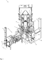
- FIG. 11 shows an enlarged schematic perspective view of the support structure 3 from FIG Figure 1 .
- the support structure 3 as a whole can also be used as an independent device 1.
- the support structure 3 is usually installed in a stationary manner on the floor and can have one or more channels 13 designed as a hollow profile. In the channels 13 arranged at floor level, connection lines for compressed air or electrical connection lines can be fed in in a protected manner.
- the support structure further comprises a central and here vertically aligned hollow profile 11 as a support unit.
- the support unit 11 carries the rotating device 15 with, here, four filling nozzles 4 rotatable about a central axis.
- the rotating device 15 also comprises a plurality of hollow profiles 12 which connect the central axis of rotation to the individual filling nozzles 4.
- the hollow profiles 12 of the rotating device 15 also serve to accommodate connecting lines in order to supply the pneumatic cylinders 7 of the bag holders 5, 6 of the filling spouts 4 with compressed air.
- the bag holders 5, 6 can be driven electrically. Electrical connection lines for driving the bag holders 5, 6 are then laid in the hollow profiles 12 of the rotating device 15. In addition, further lines can be laid in the hollow profiles 12.
- the pneumatic or electrical lines in the hollow profiles 12 are control components 20 and are reliably protected from contamination in the respective hollow profiles 12.
- the central and here vertically aligned hollow profile 11 as a support unit carries the rotating device 15 and thus also the open bags 2 to be filled during the filling process.
- the support unit 11 or the central hollow profile 11, however, has larger ones here External dimensions than would be necessary for the pure stability of the support structure 3. This is due, among other things, to the fact that control components 20 are housed inside the profile 11, which in the discussion of Figure 4 to be described in more detail.
- the upper side of the individual hollow profiles 10 to 13 is each beveled or designed like a roof.
- roof sides 17, 18 running at an angle are provided on the upper side 16 of the hollow profiles 13, so that dirt particles falling onto them from above tend to be passed on downwards.
- the hollow profiles 12 of the rotating device 15 also have beveled roof sides on their upper side in order to reduce the accumulation of dust and dirt there.
- Figure 3 shows a side view of the support structure 3 from Figure 2
- a maintenance door 14 can be seen on the vertical hollow profile 11 as a support unit, which can be opened during assembly or during subsequent maintenance in order to maintain or replace control components 20 inside the profile 11.
- Schematic is in Figure 3 an open bag 2 attached to a filler neck 4 is shown.
- One of the control components 20 in the interior of the profile 11 can be recognized by the interior of the hollow profile 13 as a channel at the lower end of the hollow profile 11 as a support unit.
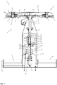
- Figure 4 shows a sectional side view of the support structure 3, the individual hollow profiles 10 to 13 being shown in section.
- Pneumatic connection lines 23 and also electrical connection and control lines 24 can be introduced into the support structure 3 through the hollow profiles 13. Due to the protected receptacle in the channel or the hollow profile 13, contamination of the individual lines 23, 24 can be reliably prevented, so that cleaning of the individual lines 23, 24 is not normally necessary during operation.
- a plurality of control components 20 are accommodated in the interior of the vertical hollow profile 11, which serves as a support unit for the rotating device 15.
- the electric motor is received as a drive 22 for the rotating device 15.
- the electric motor 22 is controlled here by the control device 25, which is also arranged in the interior of the hollow profile 11. It is possible, for example, to arrange a sensor device 27 such as a pressure sensor inside the profile 11 in order to detect the internal pressure prevailing inside the hollow profile 11.
- the pressure sensor or other sensors can be connected to the control device 25 via sensor lines 28.
- the compressed air supply takes place via the line 32 through the hollow profile of the channel 13.
- the compressed air supply is passed via the line 46 through the hollow shaft 9 to the rotating valve island 26 and supplies the valve island 26 with compressed air.
- the individual pneumatic cylinders 7 are each controlled via two control valves 21 and can be moved into one or the other end position by means of compressed air.
- Each pneumatic cylinder 7 is connected via two lines 23 and 24.
- Each line 23 and 24 serves as a supply air line and an exhaust air line, depending on the switching status of the associated control valves.
- the compressed air supplied through a line is returned after switching through the same line after switching and can then be discharged as exhaust air through an air outlet into the interior of the hollow profile by a control valve that is then open.
- Power is supplied via line 47. Further lines for the control are provided, but not shown or designated in detail.
- the internal pressure is preferably controlled in such a way that the internal pressure during operation is regularly higher than the ambient atmospheric pressure.
- a pressure gradient from inside the Outwardly, the hollow profile reliably prevents dirt and dust from entering the interior of the hollow profile 11.
- bearings 19 for the hollow shaft 9 of the rotating device 15 are fastened in the interior of the support unit designed as a hollow profile 11.
- at least one valve island 26 with several pneumatic control valves 21 is accommodated there, with which the various bag holders 5, 6 of the respective filling nozzles 4 are controlled.
- Pneumatic compressed air lines 23 and 24 are provided to the individual bag holders. The compressed air is also fed back through these air lines 23, 24 and discharged into the interior of the hollow profile 10 as exhaust air 8 on the valve island 26 rotating with it when the bag holder 5, 6 is switched from hold to open or vice versa.
- Or there is a central compressed air supply and control valves are accommodated in the hollow profiles 12 of the rotating device 15, with which the pneumatic cylinders 7 of the bag holders 5, 6 are controlled.
- the exhaust air from the pneumatic cylinders 7 is returned here and released via one or more air outlets 8 in one or more of the hollow profiles 10. This reduces the noise pollution in the vicinity of the device 1.
- an overpressure is built up in the profiles 10 to 13 so that no further additional air may have to be output in the profiles 10 to 13 in order to maintain the necessary or desired overpressure inside the hollow profiles 10 to 13 during operation.
- FIG. 4 Schematically shown in Figure 4 an air outlet 8 on the vertical hollow profile 11 as a support unit for the rotating device 15.
- the air outlet 8 emits the air of one or more grippers 5, 6 when these have been actuated.
- a partition is formed in the filler neck. Air lines through which the pneumatic cylinders of the bag holder 6 are supplied with compressed air are passed through the interior of the partition wall.
- compressed air is passed through the line 29 to the filler neck and can exit there through a hole 48 provided in it as a bag recognition device to the outside in the direction of the bag holder 6.
- the bag wall is preferably recognized by the bag detection 48 on two opposing walls.
- FIG. 3 shows a sectional view from below of the rotating device 15, the pivotable grippers 5, 6, which are each controlled via a pneumatic cylinder 7, and the here hexagonal sack holder 4 can be seen from below.
- the supply of the connecting lines takes place through the hollow profiles 10. Air and electricity are supplied via the hollow shaft 9, around which the rotating device 15 is rotatably mounted.
- control components 20 such as connecting lines and pneumatic control valves are housed in the interior of the hollow profiles 10.
- control components 20 such as connecting lines and pneumatic control valves
- several lines can be laid together inside the hollow profile.
- inexpensive standard components can be used as an electric drive or as a pneumatic valve, which do not have to meet the increased hygiene requirements when filling foodstuffs.
- a lifting device for a vibrating table which is raised from below under the sack during filling, can be carried out with internal drive and control components.
Landscapes
- Engineering & Computer Science (AREA)
- Mechanical Engineering (AREA)
- Basic Packing Technique (AREA)
- Supplying Of Containers To The Packaging Station (AREA)
- Air Transport Of Granular Materials (AREA)
Claims (14)
- Dispositif (1) destiné à verser des produits en vrac dans des sacs (2) et en particulier à verser des produits alimentaires pulvérulents dans des sacs ouverts, comprenant une structure de support (3) et au moins une tubulure de remplissage (4) laquelle est reçue sur ladite structure de support (3) et sur laquelle un sac (2) est suspendu pour le remplir et est maintenu au moyen d'au moins un support de sac (5, 6) sur la tubulure de remplissage (4),
caractérisé par le fait
que la structure de support (3) comprend au moins un profilé creux (10, 11) ayant un premier composant de commande (20) qui est logé au moins en partie dans celui-ci et y est protégé d'encrassement, et qu'une sortie d'air (8) d'un composant pneumatique (7) est prévu dans le profilé creux (10), pour mettre le profilé creux (10) sous une pression d'air plus élevée que l'environnement pendant le fonctionnement, et qu'un dispositif capteur (27) comprenant un capteur de pression est disposé dans le profilé creux (10) en tant que deuxième composant de commande (20), dans lequel le capteur de pression est prévu pour détecter pendant le fonctionnement du dispositif la pression régnant dans le profilé creux (10). - Dispositif (1) selon la revendication précédente, dans lequel le profilé creux (10) est étanché vers l'extérieur.
- Dispositif selon l'une quelconque des revendications précédentes, dans lequel au moins une vanne de commande (21) et/ou un dispositif de commande (25) est agencé(e) en tant qu'autre composant de commande (20) dans le profilé creux (10).
- Dispositif (1) selon l'une quelconque des revendications précédentes, dans lequel au moins un îlot de vannes (26) comprenant une pluralité de vannes de commande (21) est agencé en tant qu'autres composants de commande dans le profilé creux (10).
- Dispositif selon l'une quelconque des revendications précédentes, dans lequel au moins une ligne/conduite de raccordement (23, 24) est logée en tant qu'autre composant de commande dans le profilé creux (10), dans lequel, en particulier, ladite au moins une ligne/conduite de raccordement (23) est conçue de façon électrique, pneumatique ou hydraulique, et dans lequel, en particulier, au moins un câble de capteur (28) est logé dans le profilé creux (10).
- Dispositif (1) selon l'une quelconque des revendications précédentes, dans lequel le support de sac (5, 6) est fixé sur le profilé creux (10).
- Dispositif (1) selon l'une quelconque des revendications précédentes, dans lequel le support de sac (5, 6) peut être commandé via un vérin pneumatique (7) et/ou de façon électrique.
- Dispositif (1) selon la revendication précédente, dans lequel une conduite d'échappement d'air (29) du vérin pneumatique (7) débouche dans le profilé creux (10).
- Dispositif (1) selon l'une quelconque des revendications précédentes, caractérisé par un dispositif de rotation (15) ayant une pluralité de tubulures de remplissage (4) disposées sur celui-ci.
- Dispositif (1) selon l'une quelconque des revendications précédentes, dans lequel la structure de support (3) comprend une pluralité de profilés creux (11, 12).
- Dispositif (1) selon l'une quelconque des revendications précédentes, dans lequel le dispositif de rotation (15) comprend un profilé creux central (11) qui est conçu comme une unité de support (11) ainsi qu'une pluralité de profilés creux (12) aptes à tourner par rapport au profilé creux central (11), et dans lequel, en particulier, un palier et/ou un moteur d'entraînement (22) est disposé dans le profilé creux central (11).
- Dispositif selon l'une quelconque des revendications précédentes, dans lequel une bague collectrice (30) et/ou un distributeur d'air comprimé (31) et/ou un joint tournant pour un fluide pneumatique ou hydraulique est reçu(e) dans le profilé creux central (11).
- Dispositif selon l'une quelconque des revendications précédentes, dans lequel le profilé creux central (11) est relié à un poste d'alimentation (40) via au moins un canal (13) conçu en tant que profilé creux et/ou dans lequel au moins un profilé creux (12, 13) présente des côtés de toit en pente (17, 18) sur sa face supérieure (16).
- Dispositif selon l'une quelconque des revendications précédentes, comprenant une amenée de sacs (50) et au moins une amenée de produits (42, 43) et au moins un poste de fermeture de sac (44) et une évacuation de sacs (45).
Applications Claiming Priority (2)
| Application Number | Priority Date | Filing Date | Title |
|---|---|---|---|
| DE102016123810.4A DE102016123810A1 (de) | 2016-12-08 | 2016-12-08 | Vorrichtung zum Füllen von Schüttgütern in Offensäcke |
| PCT/EP2017/081988 WO2018104509A2 (fr) | 2016-12-08 | 2017-12-08 | Dispositif de remplissage de produits en vrac dans des sacs ouverts |
Publications (2)
| Publication Number | Publication Date |
|---|---|
| EP3551353A2 EP3551353A2 (fr) | 2019-10-16 |
| EP3551353B1 true EP3551353B1 (fr) | 2021-11-17 |
Family
ID=60935780
Family Applications (1)
| Application Number | Title | Priority Date | Filing Date |
|---|---|---|---|
| EP17825406.6A Active EP3551353B1 (fr) | 2016-12-08 | 2017-12-08 | Dispositif pour ensacher des produits en vrac dans des sacs |
Country Status (7)
| Country | Link |
|---|---|
| US (1) | US12043422B2 (fr) |
| EP (1) | EP3551353B1 (fr) |
| CN (1) | CN110035838B (fr) |
| CA (1) | CA3044549C (fr) |
| DE (1) | DE102016123810A1 (fr) |
| ES (1) | ES2905577T3 (fr) |
| WO (1) | WO2018104509A2 (fr) |
Families Citing this family (1)
| Publication number | Priority date | Publication date | Assignee | Title |
|---|---|---|---|---|
| DE102019119322A1 (de) * | 2019-07-17 | 2021-01-21 | Behn & Bates Maschinenfabrik Gmbh & Co. Kg | Abfüllsystem und Verfahren zum Befestigen von Säcken |
Citations (5)
| Publication number | Priority date | Publication date | Assignee | Title |
|---|---|---|---|---|
| US2634894A (en) * | 1948-04-05 | 1953-04-14 | Gen Mills Inc | Powder handling device with protected driving mechanism |
| DE2529859A1 (de) * | 1974-08-09 | 1976-02-19 | Crane Air Trac Inc | Belueftungssystem fuer laufkrankabinen, abzugshauben und dergleichen |
| DE3640520A1 (de) * | 1986-11-27 | 1988-06-09 | Rovema Gmbh | Verfahren zum dosieren und verpacken von schuettfaehigen guetern und verpackungsmaschine zur durchfuehrung des verfahrens |
| DE102014113859A1 (de) * | 2014-09-24 | 2016-03-24 | Haver & Boecker Ohg | Vorrichtung und Verfahren zum Füllen von Offensäcken |
| DE102015223525A1 (de) * | 2015-11-27 | 2016-11-03 | Voith Patent Gmbh | Messvorrichtung |
Family Cites Families (21)
| Publication number | Priority date | Publication date | Assignee | Title |
|---|---|---|---|---|
| DE75336C (de) | F. SCHWED in Nürnberg, Jacobstr. 12 | Befestigung für Rollvorhänge | ||
| US2133367A (en) * | 1936-12-28 | 1938-10-18 | Liquid Carbonic Corp | Method of charging containers with inert gas and materials |
| US2443182A (en) * | 1944-01-12 | 1948-06-15 | Clarence F Carter | Apparatus for filling containers employing vacuum and mechanical feeders |
| US2942761A (en) * | 1958-03-17 | 1960-06-28 | Fr Hesser Maschinenfabrik Ag F | Dispensing machine |
| DE3818910A1 (de) * | 1988-06-03 | 1989-12-14 | Haver & Boecker | Vorrichtung zum fuellen und verschliessen von offenen saecken |
| US6142169A (en) * | 1997-03-28 | 2000-11-07 | Tetra Laval Holdings & Finance, Sa | Sterile tank venting system for a filling machine |
| DE29803070U1 (de) * | 1998-02-23 | 1998-11-05 | Sandi, Roland, Meggen | Saugkopf für Sackentleerungsvorrichtung |
| ITBO20020523A1 (it) * | 2002-08-05 | 2004-02-06 | Azionaria Costruzioni Acma Spa | Macchina per il riempimento di contenitori. |
| DE10314634A1 (de) * | 2003-04-01 | 2004-10-14 | Khs Maschinen- Und Anlagenbau Ag, Patentabteilung | Spülbares Huborgan |
| DE10346881A1 (de) * | 2003-10-09 | 2005-05-04 | Haver & Boecker | Anlage zum Füllen und Verschließen von offenen Kunststoffsäcken |
| DE10359779B4 (de) * | 2003-12-19 | 2006-03-16 | Khs Maschinen- Und Anlagenbau Ag | Füllelement einer Füllmaschine |
| ATE430698T1 (de) | 2005-03-30 | 2009-05-15 | F B R Elpo Societa Per Azioni | Maschine zum füllen von abgedichteten weichen behältern in einer aseptischen umgebung und verfahren zu ihrem füllen |
| CN2841503Y (zh) * | 2005-11-10 | 2006-11-29 | 卢绪首 | 粉料称重全自动包装机 |
| CN200978011Y (zh) | 2006-09-26 | 2007-11-21 | 珠海天威技术开发有限公司 | 粉体灌装机 |
| DE102007015251A1 (de) * | 2007-03-27 | 2008-10-09 | Windmöller & Hölscher Kg | Maschine zum Füllen und Schließen von Säcken |
| JP4448871B2 (ja) * | 2007-07-30 | 2010-04-14 | 大和製衡株式会社 | 定量充填装置 |
| US8556620B2 (en) * | 2008-04-18 | 2013-10-15 | Sacmi Cooperativa Meccanici Imola Societa' Cooperativa | Method and apparatuses |
| DE202009000927U1 (de) * | 2009-01-24 | 2009-04-09 | Jörg von Seggern Maschinenbau GmbH | Rahmenprofil für einen Gestellrahmen |
| DE102013110016A1 (de) * | 2013-09-12 | 2015-03-12 | Khs Gmbh | Drehdurchführung sowie Vorrichtung zur Behandlung und/oder zum Transport von Behältern mit einer solchen Drehdurchführung |
| CN203664331U (zh) | 2013-12-11 | 2014-06-25 | 蚌埠市和平乳业有限责任公司 | 一种乳制品灌装台防污装置 |
| BE1024099B1 (nl) * | 2015-01-07 | 2017-11-16 | Nv Michel Van De Wiele | Gaapvormingsinrichting met ventilatie-inrichting |
-
2016
- 2016-12-08 DE DE102016123810.4A patent/DE102016123810A1/de active Pending
-
2017
- 2017-12-08 CN CN201780075526.8A patent/CN110035838B/zh active Active
- 2017-12-08 EP EP17825406.6A patent/EP3551353B1/fr active Active
- 2017-12-08 CA CA3044549A patent/CA3044549C/fr active Active
- 2017-12-08 US US16/464,481 patent/US12043422B2/en active Active
- 2017-12-08 ES ES17825406T patent/ES2905577T3/es active Active
- 2017-12-08 WO PCT/EP2017/081988 patent/WO2018104509A2/fr not_active Ceased
Patent Citations (5)
| Publication number | Priority date | Publication date | Assignee | Title |
|---|---|---|---|---|
| US2634894A (en) * | 1948-04-05 | 1953-04-14 | Gen Mills Inc | Powder handling device with protected driving mechanism |
| DE2529859A1 (de) * | 1974-08-09 | 1976-02-19 | Crane Air Trac Inc | Belueftungssystem fuer laufkrankabinen, abzugshauben und dergleichen |
| DE3640520A1 (de) * | 1986-11-27 | 1988-06-09 | Rovema Gmbh | Verfahren zum dosieren und verpacken von schuettfaehigen guetern und verpackungsmaschine zur durchfuehrung des verfahrens |
| DE102014113859A1 (de) * | 2014-09-24 | 2016-03-24 | Haver & Boecker Ohg | Vorrichtung und Verfahren zum Füllen von Offensäcken |
| DE102015223525A1 (de) * | 2015-11-27 | 2016-11-03 | Voith Patent Gmbh | Messvorrichtung |
Also Published As
| Publication number | Publication date |
|---|---|
| WO2018104509A3 (fr) | 2018-08-02 |
| CN110035838A (zh) | 2019-07-19 |
| CA3044549A1 (fr) | 2018-06-14 |
| EP3551353A2 (fr) | 2019-10-16 |
| US20190322395A1 (en) | 2019-10-24 |
| US12043422B2 (en) | 2024-07-23 |
| CN110035838B (zh) | 2022-04-08 |
| DE102016123810A1 (de) | 2018-06-14 |
| CA3044549C (fr) | 2023-10-17 |
| ES2905577T3 (es) | 2022-04-11 |
| WO2018104509A2 (fr) | 2018-06-14 |
Similar Documents
| Publication | Publication Date | Title |
|---|---|---|
| EP2920079B1 (fr) | Dispositif de traitement de sacs ouverts | |
| EP3621881B1 (fr) | Station de compactage permettant de compacter des produits en vrac dans des sacs ouverts et procédé | |
| EP3486589A1 (fr) | Dispositif de nettoyage et / ou de séchage pour caisses | |
| EP4149848A1 (fr) | Ensacheuse et procédé de fonctionnement | |
| EP2288545A1 (fr) | Emballeuse | |
| WO2017072353A2 (fr) | Dispositif permettant de remplir des contenants avec avec un produit de remplissage | |
| EP3551353B1 (fr) | Dispositif pour ensacher des produits en vrac dans des sacs | |
| EP2776347B1 (fr) | Dispositif d'alimentation pour fermetures de contenant | |
| EP1480880B1 (fr) | Machine de conditionnement sous blister | |
| DE102008050729A1 (de) | Packmaschine und Verfahren zum Füllen von Schüttgütern in Säcke | |
| EP2566797B1 (fr) | Installation pour le transport vertical d'une preforme | |
| WO2021228818A1 (fr) | Ensacheuse et procédé de fonctionnement | |
| EP1758691B1 (fr) | Procede et appareil pour le changement de phase dans un isolateur | |
| DE102005062715B4 (de) | Vorrichtung zum Befüllen von Aufnahmebehältern mit den Produkten einer Rundläuferpresse | |
| DE202020103833U1 (de) | Vakuumkammer | |
| DE602004003935T2 (de) | Struktur zum umschliessen und isolieren einer verpackungsmaschine von einer externen umgebung | |
| DE102009046069A1 (de) | Fördersystem für eine Rotationsdruckmaschine | |
| DE3023356A1 (de) | Einrichtung zur unterdrueckung der staubentwicklung bei zellenrad-blasversatzmaschinen | |
| EP1607139B1 (fr) | Appareil et méthode pour le revêtement des pilules avec un tambour rotatif | |
| EP3697722B1 (fr) | Enceinte pour une installation industrielle | |
| DE3809355C2 (fr) | ||
| WO2024156017A1 (fr) | Tête d'extrusion pour la fabrication additive | |
| CH696352A5 (de) | Abfüllanordnung und Verfahren zum Abfüllen. | |
| WO2001032536A1 (fr) | Dispositif de transport et son utilisation notamment pour le transport de films |
Legal Events
| Date | Code | Title | Description |
|---|---|---|---|
| STAA | Information on the status of an ep patent application or granted ep patent |
Free format text: STATUS: UNKNOWN |
|
| STAA | Information on the status of an ep patent application or granted ep patent |
Free format text: STATUS: THE INTERNATIONAL PUBLICATION HAS BEEN MADE |
|
| PUAI | Public reference made under article 153(3) epc to a published international application that has entered the european phase |
Free format text: ORIGINAL CODE: 0009012 |
|
| STAA | Information on the status of an ep patent application or granted ep patent |
Free format text: STATUS: REQUEST FOR EXAMINATION WAS MADE |
|
| 17P | Request for examination filed |
Effective date: 20190704 |
|
| AK | Designated contracting states |
Kind code of ref document: A2 Designated state(s): AL AT BE BG CH CY CZ DE DK EE ES FI FR GB GR HR HU IE IS IT LI LT LU LV MC MK MT NL NO PL PT RO RS SE SI SK SM TR |
|
| AX | Request for extension of the european patent |
Extension state: BA ME |
|
| DAV | Request for validation of the european patent (deleted) | ||
| DAX | Request for extension of the european patent (deleted) | ||
| STAA | Information on the status of an ep patent application or granted ep patent |
Free format text: STATUS: EXAMINATION IS IN PROGRESS |
|
| 17Q | First examination report despatched |
Effective date: 20200908 |
|
| GRAP | Despatch of communication of intention to grant a patent |
Free format text: ORIGINAL CODE: EPIDOSNIGR1 |
|
| STAA | Information on the status of an ep patent application or granted ep patent |
Free format text: STATUS: GRANT OF PATENT IS INTENDED |
|
| INTG | Intention to grant announced |
Effective date: 20210611 |
|
| GRAS | Grant fee paid |
Free format text: ORIGINAL CODE: EPIDOSNIGR3 |
|
| GRAA | (expected) grant |
Free format text: ORIGINAL CODE: 0009210 |
|
| STAA | Information on the status of an ep patent application or granted ep patent |
Free format text: STATUS: THE PATENT HAS BEEN GRANTED |
|
| AK | Designated contracting states |
Kind code of ref document: B1 Designated state(s): AL AT BE BG CH CY CZ DE DK EE ES FI FR GB GR HR HU IE IS IT LI LT LU LV MC MK MT NL NO PL PT RO RS SE SI SK SM TR |
|
| REG | Reference to a national code |
Ref country code: GB Ref legal event code: FG4D Free format text: NOT ENGLISH |
|
| REG | Reference to a national code |
Ref country code: DE Ref legal event code: R096 Ref document number: 502017012065 Country of ref document: DE |
|
| REG | Reference to a national code |
Ref country code: IE Ref legal event code: FG4D Free format text: LANGUAGE OF EP DOCUMENT: GERMAN |
|
| REG | Reference to a national code |
Ref country code: AT Ref legal event code: REF Ref document number: 1447626 Country of ref document: AT Kind code of ref document: T Effective date: 20211215 |
|
| REG | Reference to a national code |
Ref country code: NL Ref legal event code: FP |
|
| REG | Reference to a national code |
Ref country code: LT Ref legal event code: MG9D |
|
| REG | Reference to a national code |
Ref country code: ES Ref legal event code: FG2A Ref document number: 2905577 Country of ref document: ES Kind code of ref document: T3 Effective date: 20220411 |
|
| PG25 | Lapsed in a contracting state [announced via postgrant information from national office to epo] |
Ref country code: RS Free format text: LAPSE BECAUSE OF FAILURE TO SUBMIT A TRANSLATION OF THE DESCRIPTION OR TO PAY THE FEE WITHIN THE PRESCRIBED TIME-LIMIT Effective date: 20211117 Ref country code: LT Free format text: LAPSE BECAUSE OF FAILURE TO SUBMIT A TRANSLATION OF THE DESCRIPTION OR TO PAY THE FEE WITHIN THE PRESCRIBED TIME-LIMIT Effective date: 20211117 Ref country code: FI Free format text: LAPSE BECAUSE OF FAILURE TO SUBMIT A TRANSLATION OF THE DESCRIPTION OR TO PAY THE FEE WITHIN THE PRESCRIBED TIME-LIMIT Effective date: 20211117 Ref country code: BG Free format text: LAPSE BECAUSE OF FAILURE TO SUBMIT A TRANSLATION OF THE DESCRIPTION OR TO PAY THE FEE WITHIN THE PRESCRIBED TIME-LIMIT Effective date: 20220217 |
|
| PG25 | Lapsed in a contracting state [announced via postgrant information from national office to epo] |
Ref country code: IS Free format text: LAPSE BECAUSE OF FAILURE TO SUBMIT A TRANSLATION OF THE DESCRIPTION OR TO PAY THE FEE WITHIN THE PRESCRIBED TIME-LIMIT Effective date: 20220317 Ref country code: SE Free format text: LAPSE BECAUSE OF FAILURE TO SUBMIT A TRANSLATION OF THE DESCRIPTION OR TO PAY THE FEE WITHIN THE PRESCRIBED TIME-LIMIT Effective date: 20211117 Ref country code: PT Free format text: LAPSE BECAUSE OF FAILURE TO SUBMIT A TRANSLATION OF THE DESCRIPTION OR TO PAY THE FEE WITHIN THE PRESCRIBED TIME-LIMIT Effective date: 20220317 Ref country code: PL Free format text: LAPSE BECAUSE OF FAILURE TO SUBMIT A TRANSLATION OF THE DESCRIPTION OR TO PAY THE FEE WITHIN THE PRESCRIBED TIME-LIMIT Effective date: 20211117 Ref country code: NO Free format text: LAPSE BECAUSE OF FAILURE TO SUBMIT A TRANSLATION OF THE DESCRIPTION OR TO PAY THE FEE WITHIN THE PRESCRIBED TIME-LIMIT Effective date: 20220217 Ref country code: LV Free format text: LAPSE BECAUSE OF FAILURE TO SUBMIT A TRANSLATION OF THE DESCRIPTION OR TO PAY THE FEE WITHIN THE PRESCRIBED TIME-LIMIT Effective date: 20211117 Ref country code: HR Free format text: LAPSE BECAUSE OF FAILURE TO SUBMIT A TRANSLATION OF THE DESCRIPTION OR TO PAY THE FEE WITHIN THE PRESCRIBED TIME-LIMIT Effective date: 20211117 Ref country code: GR Free format text: LAPSE BECAUSE OF FAILURE TO SUBMIT A TRANSLATION OF THE DESCRIPTION OR TO PAY THE FEE WITHIN THE PRESCRIBED TIME-LIMIT Effective date: 20220218 |
|
| PG25 | Lapsed in a contracting state [announced via postgrant information from national office to epo] |
Ref country code: SM Free format text: LAPSE BECAUSE OF FAILURE TO SUBMIT A TRANSLATION OF THE DESCRIPTION OR TO PAY THE FEE WITHIN THE PRESCRIBED TIME-LIMIT Effective date: 20211117 Ref country code: SK Free format text: LAPSE BECAUSE OF FAILURE TO SUBMIT A TRANSLATION OF THE DESCRIPTION OR TO PAY THE FEE WITHIN THE PRESCRIBED TIME-LIMIT Effective date: 20211117 Ref country code: RO Free format text: LAPSE BECAUSE OF FAILURE TO SUBMIT A TRANSLATION OF THE DESCRIPTION OR TO PAY THE FEE WITHIN THE PRESCRIBED TIME-LIMIT Effective date: 20211117 Ref country code: EE Free format text: LAPSE BECAUSE OF FAILURE TO SUBMIT A TRANSLATION OF THE DESCRIPTION OR TO PAY THE FEE WITHIN THE PRESCRIBED TIME-LIMIT Effective date: 20211117 Ref country code: DK Free format text: LAPSE BECAUSE OF FAILURE TO SUBMIT A TRANSLATION OF THE DESCRIPTION OR TO PAY THE FEE WITHIN THE PRESCRIBED TIME-LIMIT Effective date: 20211117 Ref country code: CZ Free format text: LAPSE BECAUSE OF FAILURE TO SUBMIT A TRANSLATION OF THE DESCRIPTION OR TO PAY THE FEE WITHIN THE PRESCRIBED TIME-LIMIT Effective date: 20211117 |
|
| PGFP | Annual fee paid to national office [announced via postgrant information from national office to epo] |
Ref country code: IT Payment date: 20220329 Year of fee payment: 5 |
|
| REG | Reference to a national code |
Ref country code: CH Ref legal event code: PL |
|
| REG | Reference to a national code |
Ref country code: DE Ref legal event code: R097 Ref document number: 502017012065 Country of ref document: DE |
|
| PG25 | Lapsed in a contracting state [announced via postgrant information from national office to epo] |
Ref country code: MC Free format text: LAPSE BECAUSE OF FAILURE TO SUBMIT A TRANSLATION OF THE DESCRIPTION OR TO PAY THE FEE WITHIN THE PRESCRIBED TIME-LIMIT Effective date: 20211117 |
|
| PLBE | No opposition filed within time limit |
Free format text: ORIGINAL CODE: 0009261 |
|
| STAA | Information on the status of an ep patent application or granted ep patent |
Free format text: STATUS: NO OPPOSITION FILED WITHIN TIME LIMIT |
|
| 26N | No opposition filed |
Effective date: 20220818 |
|
| PG25 | Lapsed in a contracting state [announced via postgrant information from national office to epo] |
Ref country code: LU Free format text: LAPSE BECAUSE OF NON-PAYMENT OF DUE FEES Effective date: 20211208 Ref country code: IE Free format text: LAPSE BECAUSE OF NON-PAYMENT OF DUE FEES Effective date: 20211208 Ref country code: AL Free format text: LAPSE BECAUSE OF FAILURE TO SUBMIT A TRANSLATION OF THE DESCRIPTION OR TO PAY THE FEE WITHIN THE PRESCRIBED TIME-LIMIT Effective date: 20211117 |
|
| PG25 | Lapsed in a contracting state [announced via postgrant information from national office to epo] |
Ref country code: SI Free format text: LAPSE BECAUSE OF FAILURE TO SUBMIT A TRANSLATION OF THE DESCRIPTION OR TO PAY THE FEE WITHIN THE PRESCRIBED TIME-LIMIT Effective date: 20211117 Ref country code: FR Free format text: LAPSE BECAUSE OF NON-PAYMENT OF DUE FEES Effective date: 20220117 |
|
| PG25 | Lapsed in a contracting state [announced via postgrant information from national office to epo] |
Ref country code: LI Free format text: LAPSE BECAUSE OF NON-PAYMENT OF DUE FEES Effective date: 20211231 Ref country code: CH Free format text: LAPSE BECAUSE OF NON-PAYMENT OF DUE FEES Effective date: 20211231 |
|
| P01 | Opt-out of the competence of the unified patent court (upc) registered |
Effective date: 20230516 |
|
| PG25 | Lapsed in a contracting state [announced via postgrant information from national office to epo] |
Ref country code: CY Free format text: LAPSE BECAUSE OF FAILURE TO SUBMIT A TRANSLATION OF THE DESCRIPTION OR TO PAY THE FEE WITHIN THE PRESCRIBED TIME-LIMIT Effective date: 20211117 |
|
| PG25 | Lapsed in a contracting state [announced via postgrant information from national office to epo] |
Ref country code: HU Free format text: LAPSE BECAUSE OF FAILURE TO SUBMIT A TRANSLATION OF THE DESCRIPTION OR TO PAY THE FEE WITHIN THE PRESCRIBED TIME-LIMIT; INVALID AB INITIO Effective date: 20171208 |
|
| PG25 | Lapsed in a contracting state [announced via postgrant information from national office to epo] |
Ref country code: IT Free format text: LAPSE BECAUSE OF NON-PAYMENT OF DUE FEES Effective date: 20221208 |
|
| PG25 | Lapsed in a contracting state [announced via postgrant information from national office to epo] |
Ref country code: MK Free format text: LAPSE BECAUSE OF FAILURE TO SUBMIT A TRANSLATION OF THE DESCRIPTION OR TO PAY THE FEE WITHIN THE PRESCRIBED TIME-LIMIT Effective date: 20211117 |
|
| PG25 | Lapsed in a contracting state [announced via postgrant information from national office to epo] |
Ref country code: TR Free format text: LAPSE BECAUSE OF FAILURE TO SUBMIT A TRANSLATION OF THE DESCRIPTION OR TO PAY THE FEE WITHIN THE PRESCRIBED TIME-LIMIT Effective date: 20211117 |
|
| PG25 | Lapsed in a contracting state [announced via postgrant information from national office to epo] |
Ref country code: MT Free format text: LAPSE BECAUSE OF FAILURE TO SUBMIT A TRANSLATION OF THE DESCRIPTION OR TO PAY THE FEE WITHIN THE PRESCRIBED TIME-LIMIT Effective date: 20211117 |
|
| PGFP | Annual fee paid to national office [announced via postgrant information from national office to epo] |
Ref country code: GB Payment date: 20251218 Year of fee payment: 9 |
|
| PGFP | Annual fee paid to national office [announced via postgrant information from national office to epo] |
Ref country code: AT Payment date: 20251215 Year of fee payment: 9 |
|
| PGFP | Annual fee paid to national office [announced via postgrant information from national office to epo] |
Ref country code: NL Payment date: 20251217 Year of fee payment: 9 |
|
| PGFP | Annual fee paid to national office [announced via postgrant information from national office to epo] |
Ref country code: BE Payment date: 20251223 Year of fee payment: 9 |
|
| PGFP | Annual fee paid to national office [announced via postgrant information from national office to epo] |
Ref country code: ES Payment date: 20260119 Year of fee payment: 9 |
|
| PGFP | Annual fee paid to national office [announced via postgrant information from national office to epo] |
Ref country code: DE Payment date: 20251222 Year of fee payment: 9 |