EP3551433B1 - Appareil de scellement d'un emballage de lentille ophtalmique - Google Patents
Appareil de scellement d'un emballage de lentille ophtalmique Download PDFInfo
- Publication number
- EP3551433B1 EP3551433B1 EP17818630.0A EP17818630A EP3551433B1 EP 3551433 B1 EP3551433 B1 EP 3551433B1 EP 17818630 A EP17818630 A EP 17818630A EP 3551433 B1 EP3551433 B1 EP 3551433B1
- Authority
- EP
- European Patent Office
- Prior art keywords
- bonding
- lower plate
- axle
- upper plate
- mounting portion
- Prior art date
- Legal status (The legal status is an assumption and is not a legal conclusion. Google has not performed a legal analysis and makes no representation as to the accuracy of the status listed.)
- Active
Links
Images


Classifications
-
- B—PERFORMING OPERATIONS; TRANSPORTING
- B29—WORKING OF PLASTICS; WORKING OF SUBSTANCES IN A PLASTIC STATE IN GENERAL
- B29C—SHAPING OR JOINING OF PLASTICS; SHAPING OF MATERIAL IN A PLASTIC STATE, NOT OTHERWISE PROVIDED FOR; AFTER-TREATMENT OF THE SHAPED PRODUCTS, e.g. REPAIRING
- B29C66/00—General aspects of processes or apparatus for joining preformed parts
- B29C66/01—General aspects dealing with the joint area or with the area to be joined
- B29C66/05—Particular design of joint configurations
- B29C66/10—Particular design of joint configurations particular design of the joint cross-sections
- B29C66/11—Joint cross-sections comprising a single joint-segment, i.e. one of the parts to be joined comprising a single joint-segment in the joint cross-section
- B29C66/112—Single lapped joints
-
- B—PERFORMING OPERATIONS; TRANSPORTING
- B65—CONVEYING; PACKING; STORING; HANDLING THIN OR FILAMENTARY MATERIAL
- B65B—MACHINES, APPARATUS OR DEVICES FOR, OR METHODS OF, PACKAGING ARTICLES OR MATERIALS; UNPACKING
- B65B25/00—Packaging other articles presenting special problems
- B65B25/008—Packaging other articles presenting special problems packaging of contact lenses
-
- B—PERFORMING OPERATIONS; TRANSPORTING
- B29—WORKING OF PLASTICS; WORKING OF SUBSTANCES IN A PLASTIC STATE IN GENERAL
- B29C—SHAPING OR JOINING OF PLASTICS; SHAPING OF MATERIAL IN A PLASTIC STATE, NOT OTHERWISE PROVIDED FOR; AFTER-TREATMENT OF THE SHAPED PRODUCTS, e.g. REPAIRING
- B29C65/00—Joining or sealing of preformed parts, e.g. welding of plastics materials; Apparatus therefor
- B29C65/02—Joining or sealing of preformed parts, e.g. welding of plastics materials; Apparatus therefor by heating, with or without pressure
- B29C65/18—Joining or sealing of preformed parts, e.g. welding of plastics materials; Apparatus therefor by heating, with or without pressure using heated tools
-
- B—PERFORMING OPERATIONS; TRANSPORTING
- B29—WORKING OF PLASTICS; WORKING OF SUBSTANCES IN A PLASTIC STATE IN GENERAL
- B29C—SHAPING OR JOINING OF PLASTICS; SHAPING OF MATERIAL IN A PLASTIC STATE, NOT OTHERWISE PROVIDED FOR; AFTER-TREATMENT OF THE SHAPED PRODUCTS, e.g. REPAIRING
- B29C65/00—Joining or sealing of preformed parts, e.g. welding of plastics materials; Apparatus therefor
- B29C65/78—Means for handling the parts to be joined, e.g. for making containers or hollow articles, e.g. means for handling sheets, plates, web-like materials, tubular articles, hollow articles or elements to be joined therewith; Means for discharging the joined articles from the joining apparatus
- B29C65/7802—Positioning the parts to be joined, e.g. aligning, indexing or centring
-
- B—PERFORMING OPERATIONS; TRANSPORTING
- B29—WORKING OF PLASTICS; WORKING OF SUBSTANCES IN A PLASTIC STATE IN GENERAL
- B29C—SHAPING OR JOINING OF PLASTICS; SHAPING OF MATERIAL IN A PLASTIC STATE, NOT OTHERWISE PROVIDED FOR; AFTER-TREATMENT OF THE SHAPED PRODUCTS, e.g. REPAIRING
- B29C65/00—Joining or sealing of preformed parts, e.g. welding of plastics materials; Apparatus therefor
- B29C65/78—Means for handling the parts to be joined, e.g. for making containers or hollow articles, e.g. means for handling sheets, plates, web-like materials, tubular articles, hollow articles or elements to be joined therewith; Means for discharging the joined articles from the joining apparatus
- B29C65/7841—Holding or clamping means for handling purposes
-
- B—PERFORMING OPERATIONS; TRANSPORTING
- B29—WORKING OF PLASTICS; WORKING OF SUBSTANCES IN A PLASTIC STATE IN GENERAL
- B29C—SHAPING OR JOINING OF PLASTICS; SHAPING OF MATERIAL IN A PLASTIC STATE, NOT OTHERWISE PROVIDED FOR; AFTER-TREATMENT OF THE SHAPED PRODUCTS, e.g. REPAIRING
- B29C66/00—General aspects of processes or apparatus for joining preformed parts
- B29C66/01—General aspects dealing with the joint area or with the area to be joined
- B29C66/05—Particular design of joint configurations
- B29C66/10—Particular design of joint configurations particular design of the joint cross-sections
- B29C66/11—Joint cross-sections comprising a single joint-segment, i.e. one of the parts to be joined comprising a single joint-segment in the joint cross-section
- B29C66/112—Single lapped joints
- B29C66/1122—Single lap to lap joints, i.e. overlap joints
-
- B—PERFORMING OPERATIONS; TRANSPORTING
- B29—WORKING OF PLASTICS; WORKING OF SUBSTANCES IN A PLASTIC STATE IN GENERAL
- B29C—SHAPING OR JOINING OF PLASTICS; SHAPING OF MATERIAL IN A PLASTIC STATE, NOT OTHERWISE PROVIDED FOR; AFTER-TREATMENT OF THE SHAPED PRODUCTS, e.g. REPAIRING
- B29C66/00—General aspects of processes or apparatus for joining preformed parts
- B29C66/01—General aspects dealing with the joint area or with the area to be joined
- B29C66/05—Particular design of joint configurations
- B29C66/10—Particular design of joint configurations particular design of the joint cross-sections
- B29C66/13—Single flanged joints; Fin-type joints; Single hem joints; Edge joints; Interpenetrating fingered joints; Other specific particular designs of joint cross-sections not provided for in groups B29C66/11 - B29C66/12
- B29C66/131—Single flanged joints, i.e. one of the parts to be joined being rigid and flanged in the joint area
-
- B—PERFORMING OPERATIONS; TRANSPORTING
- B29—WORKING OF PLASTICS; WORKING OF SUBSTANCES IN A PLASTIC STATE IN GENERAL
- B29C—SHAPING OR JOINING OF PLASTICS; SHAPING OF MATERIAL IN A PLASTIC STATE, NOT OTHERWISE PROVIDED FOR; AFTER-TREATMENT OF THE SHAPED PRODUCTS, e.g. REPAIRING
- B29C66/00—General aspects of processes or apparatus for joining preformed parts
- B29C66/01—General aspects dealing with the joint area or with the area to be joined
- B29C66/05—Particular design of joint configurations
- B29C66/20—Particular design of joint configurations particular design of the joint lines, e.g. of the weld lines
- B29C66/24—Particular design of joint configurations particular design of the joint lines, e.g. of the weld lines said joint lines being closed or non-straight
- B29C66/242—Particular design of joint configurations particular design of the joint lines, e.g. of the weld lines said joint lines being closed or non-straight said joint lines being closed, i.e. forming closed contours
-
- B—PERFORMING OPERATIONS; TRANSPORTING
- B29—WORKING OF PLASTICS; WORKING OF SUBSTANCES IN A PLASTIC STATE IN GENERAL
- B29C—SHAPING OR JOINING OF PLASTICS; SHAPING OF MATERIAL IN A PLASTIC STATE, NOT OTHERWISE PROVIDED FOR; AFTER-TREATMENT OF THE SHAPED PRODUCTS, e.g. REPAIRING
- B29C66/00—General aspects of processes or apparatus for joining preformed parts
- B29C66/01—General aspects dealing with the joint area or with the area to be joined
- B29C66/05—Particular design of joint configurations
- B29C66/20—Particular design of joint configurations particular design of the joint lines, e.g. of the weld lines
- B29C66/24—Particular design of joint configurations particular design of the joint lines, e.g. of the weld lines said joint lines being closed or non-straight
- B29C66/244—Particular design of joint configurations particular design of the joint lines, e.g. of the weld lines said joint lines being closed or non-straight said joint lines being non-straight, e.g. forming non-closed contours
-
- B—PERFORMING OPERATIONS; TRANSPORTING
- B29—WORKING OF PLASTICS; WORKING OF SUBSTANCES IN A PLASTIC STATE IN GENERAL
- B29C—SHAPING OR JOINING OF PLASTICS; SHAPING OF MATERIAL IN A PLASTIC STATE, NOT OTHERWISE PROVIDED FOR; AFTER-TREATMENT OF THE SHAPED PRODUCTS, e.g. REPAIRING
- B29C66/00—General aspects of processes or apparatus for joining preformed parts
- B29C66/50—General aspects of joining tubular articles; General aspects of joining long products, i.e. bars or profiled elements; General aspects of joining single elements to tubular articles, hollow articles or bars; General aspects of joining several hollow-preforms to form hollow or tubular articles
- B29C66/51—Joining tubular articles, profiled elements or bars; Joining single elements to tubular articles, hollow articles or bars; Joining several hollow-preforms to form hollow or tubular articles
- B29C66/53—Joining single elements to tubular articles, hollow articles or bars
- B29C66/534—Joining single elements to open ends of tubular or hollow articles or to the ends of bars
- B29C66/5346—Joining single elements to open ends of tubular or hollow articles or to the ends of bars said single elements being substantially flat
- B29C66/53461—Joining single elements to open ends of tubular or hollow articles or to the ends of bars said single elements being substantially flat joining substantially flat covers and/or substantially flat bottoms to open ends of container bodies
-
- B—PERFORMING OPERATIONS; TRANSPORTING
- B29—WORKING OF PLASTICS; WORKING OF SUBSTANCES IN A PLASTIC STATE IN GENERAL
- B29C—SHAPING OR JOINING OF PLASTICS; SHAPING OF MATERIAL IN A PLASTIC STATE, NOT OTHERWISE PROVIDED FOR; AFTER-TREATMENT OF THE SHAPED PRODUCTS, e.g. REPAIRING
- B29C66/00—General aspects of processes or apparatus for joining preformed parts
- B29C66/80—General aspects of machine operations or constructions and parts thereof
- B29C66/81—General aspects of the pressing elements, i.e. the elements applying pressure on the parts to be joined in the area to be joined, e.g. the welding jaws or clamps
- B29C66/816—General aspects of the pressing elements, i.e. the elements applying pressure on the parts to be joined in the area to be joined, e.g. the welding jaws or clamps characterised by the mounting of the pressing elements, e.g. of the welding jaws or clamps
- B29C66/8161—General aspects of the pressing elements, i.e. the elements applying pressure on the parts to be joined in the area to be joined, e.g. the welding jaws or clamps characterised by the mounting of the pressing elements, e.g. of the welding jaws or clamps said pressing elements being supported or backed-up by springs or by resilient material
-
- B—PERFORMING OPERATIONS; TRANSPORTING
- B29—WORKING OF PLASTICS; WORKING OF SUBSTANCES IN A PLASTIC STATE IN GENERAL
- B29C—SHAPING OR JOINING OF PLASTICS; SHAPING OF MATERIAL IN A PLASTIC STATE, NOT OTHERWISE PROVIDED FOR; AFTER-TREATMENT OF THE SHAPED PRODUCTS, e.g. REPAIRING
- B29C66/00—General aspects of processes or apparatus for joining preformed parts
- B29C66/80—General aspects of machine operations or constructions and parts thereof
- B29C66/81—General aspects of the pressing elements, i.e. the elements applying pressure on the parts to be joined in the area to be joined, e.g. the welding jaws or clamps
- B29C66/816—General aspects of the pressing elements, i.e. the elements applying pressure on the parts to be joined in the area to be joined, e.g. the welding jaws or clamps characterised by the mounting of the pressing elements, e.g. of the welding jaws or clamps
- B29C66/8163—Self-aligning to the joining plane, e.g. mounted on a ball and socket
-
- B—PERFORMING OPERATIONS; TRANSPORTING
- B29—WORKING OF PLASTICS; WORKING OF SUBSTANCES IN A PLASTIC STATE IN GENERAL
- B29C—SHAPING OR JOINING OF PLASTICS; SHAPING OF MATERIAL IN A PLASTIC STATE, NOT OTHERWISE PROVIDED FOR; AFTER-TREATMENT OF THE SHAPED PRODUCTS, e.g. REPAIRING
- B29C66/00—General aspects of processes or apparatus for joining preformed parts
- B29C66/80—General aspects of machine operations or constructions and parts thereof
- B29C66/81—General aspects of the pressing elements, i.e. the elements applying pressure on the parts to be joined in the area to be joined, e.g. the welding jaws or clamps
- B29C66/816—General aspects of the pressing elements, i.e. the elements applying pressure on the parts to be joined in the area to be joined, e.g. the welding jaws or clamps characterised by the mounting of the pressing elements, e.g. of the welding jaws or clamps
- B29C66/8167—Quick change joining tools or surfaces
-
- B—PERFORMING OPERATIONS; TRANSPORTING
- B29—WORKING OF PLASTICS; WORKING OF SUBSTANCES IN A PLASTIC STATE IN GENERAL
- B29C—SHAPING OR JOINING OF PLASTICS; SHAPING OF MATERIAL IN A PLASTIC STATE, NOT OTHERWISE PROVIDED FOR; AFTER-TREATMENT OF THE SHAPED PRODUCTS, e.g. REPAIRING
- B29C66/00—General aspects of processes or apparatus for joining preformed parts
- B29C66/80—General aspects of machine operations or constructions and parts thereof
- B29C66/82—Pressure application arrangements, e.g. transmission or actuating mechanisms for joining tools or clamps
- B29C66/824—Actuating mechanisms
-
- B—PERFORMING OPERATIONS; TRANSPORTING
- B29—WORKING OF PLASTICS; WORKING OF SUBSTANCES IN A PLASTIC STATE IN GENERAL
- B29C—SHAPING OR JOINING OF PLASTICS; SHAPING OF MATERIAL IN A PLASTIC STATE, NOT OTHERWISE PROVIDED FOR; AFTER-TREATMENT OF THE SHAPED PRODUCTS, e.g. REPAIRING
- B29C66/00—General aspects of processes or apparatus for joining preformed parts
- B29C66/80—General aspects of machine operations or constructions and parts thereof
- B29C66/83—General aspects of machine operations or constructions and parts thereof characterised by the movement of the joining or pressing tools
- B29C66/832—Reciprocating joining or pressing tools
- B29C66/8322—Joining or pressing tools reciprocating along one axis
-
- B—PERFORMING OPERATIONS; TRANSPORTING
- B29—WORKING OF PLASTICS; WORKING OF SUBSTANCES IN A PLASTIC STATE IN GENERAL
- B29C—SHAPING OR JOINING OF PLASTICS; SHAPING OF MATERIAL IN A PLASTIC STATE, NOT OTHERWISE PROVIDED FOR; AFTER-TREATMENT OF THE SHAPED PRODUCTS, e.g. REPAIRING
- B29C66/00—General aspects of processes or apparatus for joining preformed parts
- B29C66/80—General aspects of machine operations or constructions and parts thereof
- B29C66/84—Specific machine types or machines suitable for specific applications
- B29C66/843—Machines for making separate joints at the same time in different planes; Machines for making separate joints at the same time mounted in parallel or in series
- B29C66/8432—Machines for making separate joints at the same time mounted in parallel or in series
-
- B—PERFORMING OPERATIONS; TRANSPORTING
- B65—CONVEYING; PACKING; STORING; HANDLING THIN OR FILAMENTARY MATERIAL
- B65B—MACHINES, APPARATUS OR DEVICES FOR, OR METHODS OF, PACKAGING ARTICLES OR MATERIALS; UNPACKING
- B65B51/00—Devices for, or methods of, sealing or securing package folds or closures; Devices for gathering or twisting wrappers, or necks of bags
- B65B51/10—Applying or generating heat or pressure or combinations thereof
- B65B51/14—Applying or generating heat or pressure or combinations thereof by reciprocating or oscillating members
-
- B—PERFORMING OPERATIONS; TRANSPORTING
- B65—CONVEYING; PACKING; STORING; HANDLING THIN OR FILAMENTARY MATERIAL
- B65B—MACHINES, APPARATUS OR DEVICES FOR, OR METHODS OF, PACKAGING ARTICLES OR MATERIALS; UNPACKING
- B65B7/00—Closing containers or receptacles after filling
- B65B7/16—Closing semi-rigid or rigid containers or receptacles not deformed by, or not taking-up shape of, contents, e.g. boxes or cartons
- B65B7/28—Closing semi-rigid or rigid containers or receptacles not deformed by, or not taking-up shape of, contents, e.g. boxes or cartons by applying separate preformed closures, e.g. lids, covers
- B65B7/2842—Securing closures on containers
- B65B7/2878—Securing closures on containers by heat-sealing
-
- B—PERFORMING OPERATIONS; TRANSPORTING
- B29—WORKING OF PLASTICS; WORKING OF SUBSTANCES IN A PLASTIC STATE IN GENERAL
- B29C—SHAPING OR JOINING OF PLASTICS; SHAPING OF MATERIAL IN A PLASTIC STATE, NOT OTHERWISE PROVIDED FOR; AFTER-TREATMENT OF THE SHAPED PRODUCTS, e.g. REPAIRING
- B29C66/00—General aspects of processes or apparatus for joining preformed parts
- B29C66/01—General aspects dealing with the joint area or with the area to be joined
- B29C66/05—Particular design of joint configurations
- B29C66/20—Particular design of joint configurations particular design of the joint lines, e.g. of the weld lines
- B29C66/24—Particular design of joint configurations particular design of the joint lines, e.g. of the weld lines said joint lines being closed or non-straight
- B29C66/242—Particular design of joint configurations particular design of the joint lines, e.g. of the weld lines said joint lines being closed or non-straight said joint lines being closed, i.e. forming closed contours
- B29C66/2422—Particular design of joint configurations particular design of the joint lines, e.g. of the weld lines said joint lines being closed or non-straight said joint lines being closed, i.e. forming closed contours being circular, oval or elliptical
- B29C66/24221—Particular design of joint configurations particular design of the joint lines, e.g. of the weld lines said joint lines being closed or non-straight said joint lines being closed, i.e. forming closed contours being circular, oval or elliptical being circular
-
- B—PERFORMING OPERATIONS; TRANSPORTING
- B29—WORKING OF PLASTICS; WORKING OF SUBSTANCES IN A PLASTIC STATE IN GENERAL
- B29C—SHAPING OR JOINING OF PLASTICS; SHAPING OF MATERIAL IN A PLASTIC STATE, NOT OTHERWISE PROVIDED FOR; AFTER-TREATMENT OF THE SHAPED PRODUCTS, e.g. REPAIRING
- B29C66/00—General aspects of processes or apparatus for joining preformed parts
- B29C66/80—General aspects of machine operations or constructions and parts thereof
- B29C66/84—Specific machine types or machines suitable for specific applications
- B29C66/849—Packaging machines
-
- B—PERFORMING OPERATIONS; TRANSPORTING
- B29—WORKING OF PLASTICS; WORKING OF SUBSTANCES IN A PLASTIC STATE IN GENERAL
- B29L—INDEXING SCHEME ASSOCIATED WITH SUBCLASS B29C, RELATING TO PARTICULAR ARTICLES
- B29L2011/00—Optical elements, e.g. lenses, prisms
- B29L2011/0016—Lenses
- B29L2011/0041—Contact lenses
-
- B—PERFORMING OPERATIONS; TRANSPORTING
- B29—WORKING OF PLASTICS; WORKING OF SUBSTANCES IN A PLASTIC STATE IN GENERAL
- B29L—INDEXING SCHEME ASSOCIATED WITH SUBCLASS B29C, RELATING TO PARTICULAR ARTICLES
- B29L2031/00—Other particular articles
- B29L2031/712—Containers; Packaging elements or accessories, Packages
- B29L2031/7162—Boxes, cartons, cases
- B29L2031/7164—Blister packages
-
- B—PERFORMING OPERATIONS; TRANSPORTING
- B65—CONVEYING; PACKING; STORING; HANDLING THIN OR FILAMENTARY MATERIAL
- B65D—CONTAINERS FOR STORAGE OR TRANSPORT OF ARTICLES OR MATERIALS, e.g. BAGS, BARRELS, BOTTLES, BOXES, CANS, CARTONS, CRATES, DRUMS, JARS, TANKS, HOPPERS, FORWARDING CONTAINERS; ACCESSORIES, CLOSURES, OR FITTINGS THEREFOR; PACKAGING ELEMENTS; PACKAGES
- B65D2585/00—Containers, packaging elements or packages specially adapted for particular articles or materials
- B65D2585/54—Containers, packaging elements or packages specially adapted for particular articles or materials for articles of special shape not otherwise provided for
- B65D2585/545—Contact lenses
Definitions
- the invention relates to an apparatus for thermally bonding together a cover film of an ophthalmic lens package, such as a contact lens package, in particular a soft contact lens package, and a base part of the ophthalmic lens package.
- an ophthalmic lens package such as a contact lens package, in particular a soft contact lens package
- the adhesion of the cover film to the packaging must be such that it is sealed against the ingress of foreign substances from the outside and that it shall prevent the saline solution from leaking out.
- the packaging must not be damaged, for example, during the sterilization step, which normally takes place in an autoclave.
- the peeling force required to remove the cover film from the base part, that is to say to open the packaging should not exceed a maximum value in order that the user is able to open the packaging with a reasonable amount of effort while ensuring the crucial sealing requirements discussed previously.
- Apparatuses known in the art include a bonding head having a bonding contour support, a heatable bonding contour and a carrier.
- a rubber mount associated with the bonding head serves as a joint element and allows the bonding contour support to be tilted about axes that are perpendicular to guide bolts allowing for a linear displacement of the bonding head relative to the carrier.
- This kind of apparatus has several disadvantages especially in respect of the above-mentioned demands that must be met when packaging contact lenses.
- the bonding head is prone to rotational movement as the rubber mount does not prevent rotational movement around the displacement axis along the guide bolts resulting in a twisting of the rubber mount which leads to a rotation of the bonding contour with respect to the packaging.
- Even slight rotation of the rubber mount may cause deficiencies in the sealing of the packaging preventing the packaging from meeting the strict requirements.
- material fatigue of the rubber mount will have anticipated negative influence on the sealing quality of the device.
- the movement of the holding device and/or the bonding unit must be such that those surfaces of the holding device and of the bonding unit which transfer the sealing pressure to the packaging are very exactly parallel to one another while the orientation of the bonding contour with respect to the packaging must remain in an accurate predetermined position as even very slight fluctuations can result in significant variations in the sealing pressure and therefore in a seal that does not meet the requirements mentioned.
- an apparatus for thermally bonding together a cover film of an ophthalmic lens package such as a contact lens package, in particular a soft contact lens package, and a base part of the ophthalmic lens package, is suggested.
- the apparatus comprises:
- the cardanic joint comprises two plates, an upper plate and a lower plate, the upper plate being fixedly attached to the mounting portion of the bonding stamp and holding a first axle having a first longitudinal axis forming the first rotational axis and the lower plate being fixedly attached to the bonding head and holding a second axle having a second longitudinal axis forming the second rotational axis, and wherein the cardanic joint further comprises a coupler holding both the first and the second axle, the coupler pivotably connecting the upper and lower plates.
- each of the upper and lower plates comprises projections and recesses, which are alternatingly arranged along the circumference of the upper and of the lower plate respectively, the projections of the upper plate extending towards the lower plate and into a corresponding one of the recesses of the lower plate, and the projections of the lower plate extending towards the upper plate and into a corresponding one of the recesses of the upper plate.
- the articulated connector comprises an interior space surrounded by the projections and recesses of the upper and lower plates, and wherein the coupler is arranged in the interior space of the articulated connector.
- the projections of each of the upper or lower plates are arranged diametrically opposite to each other, wherein each of the projections has a through-hole extending radially through the respective projection with the axes of the through-holes of diametrically oppositely arranged projections coinciding and wherein the first and second axles are accommodated in the through-holes of the projections of the upper and lower plates, respectively.
- the first axle comprises two axle elements arranged in the articulated connector such that the two axle elements are aligned and form the first axle, and wherein the two axle elements of the first axle are arranged in the articulated connector such that the two axle elements forming the first axle abut to the second axle in a zone where longitudinal axes of the respective axles are crossing.
- the articulated connector comprises at least one attenuator arranged between the upper and the lower plate.
- the at least one attenuator is arranged between the upper and the lower plate in a peripheral zone of the upper and lower plates.
- the articulated connector comprises at least two attenuators, one attenuator being arranged between the upper plate and the coupler and the second attenuator being arranged between the coupler and the lower plate.
- the attenuator is made of rubber.
- the articulated connector comprises a circumferentially running groove arranged at the circumference of the articulated connector in the projections of the upper and lower plates and wherein the articulated connector further comprises a retainer ring arranged in the groove and locking the first and second axles in their respective position.
- At least one of the upper or lower plate comprises a locking bore and at least one of the mounting portion or bonding head comprises a locking bolt cooperating with the locking bore and rotationally locking the articulated connector with respect to the mounting portion or to the bonding head, respectively.
- At least one of the upper or lower plate comprises a positioning bolt and at least one of the mounting portion or bonding head comprises a positioning bore cooperating with the positioning bolt and rotationally locking the articulated connector with respect to the mounting portion or to the bonding head, respectively.
- the apparatus uses a cardanic joint having two, and only two, rotational axes arranged such that the bonding contour of the bonding head will be in the plane of the upper surface of the base part when pressure is applied to the cover film pressed onto the upper surface of the base part.
- the apparatus allows for a very accurate positioning of the bonding head and prevents twisting of the bonding head around the displacement axis of the apparatus, resulting in reproducible thermal bonding of the cover film to the base part of an ophthalmic lens package.
- the articulated connector according to the invention allows for a high-speed operation of the bonding step, as the bonding head has a precise orientation which is insured by the cardanic joint having only two rotational axis.
- the articulated connector according to the invention is particularly adapted for generating a uniform pressure along the join between the upper surface of the base part and the cover film for ensuring a good bond between the base part and the cover film.
- All lens packages will have to meet the high requirements with regards to quality and reproducibility of the bond.
- one prerequisite of a good bond is a pressure along the join which is as uniform as possible.
- the upper surfaces of individual base parts with the overlying cover film are in practice not always arranged exactly in the same plane, especially since there are always a multiplicity of such base parts arranged on a carrier at the same time and bonded to the cover film at the same time.
- the bonding contour may tilt about the cardanic joint in the event of a base part not being arranged exactly parallel to the bonding contour, resulting in a pivoted bonding head applying a uniform pressure along the join between the base part in the cover film.
- the apparatus according to the invention ensures a proper rotational orientation of the bonding head with respect to the lens package to be bonded as the cardanic joint prevents twisting of the bonding head with respect to the mounting portion and to the carrier receiving the packagings (pieces of packaging) that are to be sealed. This is a further prerequisite for meeting the quality requirements as even a slight rotational movement of the bonding head around the displacement axis may result in seals not meeting the strict requirements.
- the articulated connector may have any suitable shape, such as cylindrical with a circular cross-section or an oblong cross-section or with a rectangular cross-section or any other cross-section.
- the articulated connector according to the invention additionally has excellent resistance against fatigue, as most of the parts, if not all, may be particularly made of metal, in particular of stainless steel. Even if parts of the connector, such as attenuators, may be subject to fatigue due to repeatedly applied loads, there is no need to replace the entire articulated connector. The structural damage of the parts in question being locally contained, exchanging only the parts which are weakened by the cyclic loading will be sufficient.
- the projections and recesses engender an interior space further delimited by the upper and lower plate.
- the coupler may be particularly advantageously arranged in the interior space within the articulated connector for connecting the upper and lower plates of the articulated connector.
- the first and second axles may be accommodated in the through-holes and will allow for holding the first and the second axles.
- the first and second axles will then, by way of the coupler, pivotably connect the upper and lower plates of the articulated connector and allow for very accurate positioning of the bonding contour with respect to the upper surface of the corresponding base part. Radially is to be understood as running straight-lined from one point.
- One axle may comprise two axle elements such that the two axle elements are aligned to form the first or the second axle (it is to be noted that either the first axle or the second axle may be formed by two axle elements as well) and allows for easy accommodation of the two axles in the articulated connector.
- the two axle elements will then be configured to abut to the second axle in the zone where the longitudinal axes of the two axles are crossing.
- the articulated connector may comprise at least one attenuator arranged between the upper and the lower plate in order to attenuate the tilting movement of the articulated connector and allowing for return of the bonding head to the starting position.
- These attenuators may be easily exchanged in case they need to be renewed due to fatigue. This may particularly be advantageous when the attenuators are made of rubber. In case the attenuators are damaged due to fatigue, these damaged attenuators may be easily replaced by new attenuators without having to replace of the complete articulated connector.
- at least two attenuators, particularly two pairs of attenuators may be arranged between the upper and the lower plates in a peripheral zone of the upper and lower plates. The peripheral zone of the upper and lower plates is a zone arranged between the interior space and the outer radial circumference of the articulated connector.
- the at least two attenuators may particularly be arranged between the projection of the upper plate and the recess of the lower plate or between the projection of the lower plate and the recess of the upper plate.
- two pairs of attenuators may be arranged between the upper and the lower plates, the first pair being arranged between diametrically opposite projections of the upper plate and recesses of the lower plate and the second pair being arranged between diametrically opposite projections of the lower plate and recesses of the upper plate.
- the attenuators may particularly be replaceable and the elastic attenuation of the articulated connector may be adjusted to the requirements by the use of O-rings having customized elasticities and will hence have an impact on the rigidity of the articulated connector.
- attenuators each have a hardness of 55 Shore A or more.
- the upper limit of the hardness may be chosen according to the needs, the attenuators particularly have a hardness of up to 150 Shore A.
- the material the O-ring is made of may also be chosen depending on other mechanical and thermal requirements.
- the attenuators may particularly be configured (for example by adjusting the thickness of the attenuators) to permanently apply a force between the upper and lower plates of the articulated connector such that the attenuators restore the starting position of the articulated connector between each bonding cycle. Additionally, the use of such attenuators results in an articulated connector free of clearance.
- the attenuators may have each a thickness that extends from the first plate to the second plate in the starting position of at least 0.15 mm.
- a thickness that extends from the first plate to the second plate is comprised between 0.2mm and 0.5mm.
- the circumferentially running groove receives a retainer ring which locks the first and the second axles in their respective position, in particular when the first and second axles are accommodated in the through-holds of the projections of the upper and lower plates.
- the circumferentially running groove may be, for example, an indentation which is radially arranged at the periphery of the articulated connector and extending from a radial outer surface of the articulated connector towards a center of the articulated connector which is arranged at the intersection of the first and the second axles.
- the retainer ring is particularly removably arranged in the groove or in the indentation. Such removable retainer ring allows for unlocking the first and second axles for easy removal of the first and second axles and simple disassembly of the articulated connector and access to the interior space of the articulated connector.
- the first and second axles may particularly form-fitted allowing for gliding removal of the axles from the articulated connector when the retainer ring is removed.
- a disassembly of the articulated connector may particularly be advantageous for replacing parts such as the attenuators, which may be deteriorated due to fatigue.
- Locking bores in the upper or lower plate as well as locking bolts may be arranged in the mounting portion or in the bonding head and allow for rotationally locking the articulated connector with respect to the mounting portion or to the bonding head.
- the locking bore may as an alternative be arranged in the mounting portion or in the bonding head and the locking bolt accordingly in the upper or in the lower plates.
- the locking bolts may, for example, be pins, screws or any other suitable locking element.
- the apparatus according to the invention may also be provided with both locking bores and positioning bolts in the upper or lower plate and corresponding locking bolts and positioning bores in the mounting portion or in the bonding head.
- This latter configuration allows for a predetermined rotational orientation of the bonding head during assembly of the apparatus when two locking elements are present and the configuration avoids an unintentional rotation around the displacement axis of the apparatus during assembly.
- the locking bolts and corresponding locking bores may be of different size such that an assembly in an incorrect rotational orientation will not be possible.
- the afore-mentioned embodiments are practical embodiments for thermally bonding together a cover film of an ophthalmic lens package and a base part of the ophthalmic lens package.
- Fig. 1 shows an embodiment of a carrier 2 comprising essentially a support 21 on which a number of individual holding elements 22 are arranged in a well-defined position. In the embodiment shown in FIG 1 , five holding elements 22 are arranged on the carrier 2.
- the holding elements 22 are each suitable for accommodating a base part 12 of a contact lens package 1.
- Such a base part 12 and packaging 1 comprising a base part 12 and a cover film 11, which can be accommodated by the holding elements 22, are shown in Fig. 2a and Fig. 2b , respectively.
- a cover film 11 is then placed onto the base part 12 and bonded it to. The manner in which the bonding of the base part 12 and the cover film 11 can be affected will be described in more detail below.
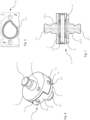
- Fig. 3 shows a bonding unit 3 and its individual components.
- the bonding unit 3 comprises a mounting plate 4 and a bonding stamp 5.
- the bonding stamp 5 extends downwardly from the mounting plate 4 towards the carrier 2 above which the bonding unit 3 will be arranged during operation.
- the bonding stamp 5 further comprises a mounting portion 51 which is fixedly attached to the mounting plate 4 and a bonding head 52 arranged beneath the mounting portion 51.
- the bonding head 52 has a heatable bonding contour 53 which is arranged on the side of the bonding head 52 facing the carrier 2 during operation. The heatable bonding contour 53 will come into contact with the surface of the cover film 11 remote from the base part 12 during the thermal bonding of base part 12 and cover film 11.
- the heatable bonding contour 53 is arranged on a contact plate 54 and bonds the cover film 11 to an upper surface of the base part 12 along the heatable bonding contour 53.
- the shape of the heatable bonding contour 53 corresponds to the desired shape of the join to be generated between the cover film 11 and the upper surface of the base part 12.
- the shape of the bonding contour 53 approximately the shape of a droplet and can be seen in more detail in Fig. 5 , in which the contact plate 54 is shown in a view from below.
- the bonding unit 3 also has an articulated connector which is a cardanic joint 6.
- the cardanic joint 6 arranged between the mounting portion 51 and the bonding head 52 and pivotably connects the bonding stamp 5 to the mounting plate 4.
- One side of the cardanic joint 6 is attached to the mounting portion 51 via a first mounting pin 77 and the other side of the cardanic joint 6 is attached to the bonding head 52 via a second mounting pin 87.
- the cardanic joint 6 connects the bonding head 52 and the mounting portion 51 in a manner so as to allow for tilting of the bonding head 52 relative to the mounting portion 51.
- the bonding unit 3 further comprises an actuator 10 performing a linear relative movement of the bonding stamp 5 towards and away of the carrier 2 along a displacement axis.
- an actuator may be arranged such that the carrier 2 performs a linear relative movement towards and away from the bonding stamp 5.
- the actuator 10 is configured to lower, for example pneumatically, the bonding stamp 5 and thereby pressing the heated bonding contour 53 against the cover film 11 placed onto the base part 12 in order to bond the cover film 11 to the base part 12.
- Fig. 4 shows a further cross-sectional side view of the bonding unit 3 shown in Fig. 3 .
- the first and second mounting pins 77 and 87 are maintained in position in bores in the mounting portion 51 and in the bonding head 52 by screws 78 and 88.
- the mounting pins have recesses into which the screws 78 and 88 are inserted in order to lock the cardanic joint 6 in the mounting portion 51 or in the bonding head 52.
- the articulated connector connecting the bonding head 52 to the mounting portion 51 is a cardanic joint 6 having two rotational axes, a first and a second rotational axis.
- the first rotational axis is arranged normal to the displacement axis of the apparatus and the second rotational axis is arranged orthogonal to the first rotational axis.
- the cardanic joint comprises two plates, an upper plate 7 and a lower plate 8.
- the upper plate 7 is fixedly attached to the mounting portion 51 of the bonding stamp 5 by the mounting pin 77 and holds a first axle 71 having a first longitudinal axis forming the first rotational axis.
- the lower plate 8 is fixedly attached to the bonding head 52 by the mounting pin 87 and holds a second axle 81 having a second longitudinal axis forming the second rotational axis. Both the first and the second axles 71, 81 are connected by a coupler 9, thereby pivotably connecting the upper and lower plates. The function of the coupler 9 will be described in more detail below.
- each of the upper and lower plates comprise each two projections 72, 82 and two recesses 73, 83 which are alternatively be arranged along the circumference of the upper and of the lower plate 7, 8 respectively and diametrically opposite to each other.
- the projections 72 of the upper plate 7 extend towards the lower plate 8 and into a corresponding one of the recesses 83 of the lower plate 8.
- the projections 82 of the lower plate 8 extend towards the upper plate 7 and into a corresponding one of the recesses 73 of the upper plate 7.
- Each of the projections 72, 82 has a through-hole 74, 84 extending radially through the respective projection 72, 82 and holding the first and second axles 71, 81.
- the first and second axles 71, 81 are press-fitted in the through-holes 74, 84 such that each of the axles are locked in each respective projection without further locking element.
- the cardanic joint 6 further comprises an interior space 61 which is surrounded by the projections 72, 82 and recesses 73, 83 and by the upper and lower plates 7, 8.
- the upper and lower plates 7, 8 comprises a locking bore 75, 85 for cooperating with the locking bolts 55, 56 on the mounting portion 51 or the bonding head 52 thereby rotationally locking the cardanic joint 6 with respect to the mounting portion 51 or to the bonding head 52, respectively.
- Each of the upper and lower plates 7, 8 may comprise more than one locking bore 75, 85 which may be non-symmetrical for secure a positioning of the cardanic joint 6 during assembly of the apparatus.
- the coupler 9 pivotably holds both the first and the second axle 71, 81 in an orthogonal position to one another pivotably connects the upper and lower plates 7, 8.
- the coupler 9 can be seen in more detail in Fig. 10 for the second embodiment shown and its function described in detail below.
- the cardanic joint 6 comprises two attenuators 62 in form of O-rings 621, 622, one O-ring 621 being arranged between the upper plate 7 and the coupler 9 and the second O-ring being arranged between the coupler 9 and the lower plate 8.
- the O-rings 621, 622 of may be made of rubber.
- the O-ring 621, 622 act as returners which restore the starting position between each bonding cycle.
- a second embodiment is shown in Fig. 8 to Fig. 11 .
- the cardanic joint 6 in the embodiment shown particularly in Fig. 8 comprises a circumferentially running groove 63 arranged at the circumference of the cardanic joint 6 in the projections 72, 82 of the upper and lower plates 7, 8.
- a retainer ring 64 is arranged in the groove 63 and locks the first and second axles 71, 81 in their respective position.
- the first and second axles 71, 81 are not press-fitted in the through holes 74, 84, but rather form-fitted such that the axles 71, 81 may easily be removed from the cardanic joint 6 in the absence of the retainer ring 64.
- the retainer ring 64 holds the axles 71, 81 in their position within the articulated connector 6 and avoids a transitional displacement of the axles 71, 81.
- Figure 9 shows an cardanic joint 6 having a locking bore 75 and a positioning bolt 76 on the upper plate 7 for cooperating with a locking bolt 55, 56 and a positioning bore 57, 58 on the mounting portion 51 or the bonding head 52 thereby rotationally locking the cardanic joint 6 with respect to the mounting portion 51 or to the bonding head 52, respectively and ensuring proper orientation during assembly due to the asymmetric design of the locking bore 75 and a positioning bolt 76.
- the cardanic joint 6 comprises four attenuators 621, 622 arranged in a peripheral zone of the cardanic joint 6 between the upper and the lower plates 7, 8.
- the attenuators 621, 622 are formed by parts of O-rings and are disposed in pairs between the projections 72 of the upper plate 7 and the recesses 83 of the lower plate 8 and between the projections 82 of the lower plate 8 and the recesses 73 of the upper plate 7.
- the pairs of attenuators 621, 622 are arranged diametrically opposite to each other in the respective pair 621, 622.
- two O-rings may be arranged in the interior space 61 of the cardanic joint 6, one O-ring being arranged between the upper plate 7 and the coupler and the second O-ring between the coupler 9 and the lower plate 8 as described for the previous embodiment.
- the cardanic joint 6 further comprises a coupler 9 arranged in the interior space 61 of the cardanic joint 6.
- the coupler 9 is formed by a cylindrical annulus.
- the coupler 9 is provided with two pairs of diametrically opposite through-holes extending radially from the rotational axis of the cylindrical annulus through the wall of the cylindrical annulus with the axes of the diametrically oppositely arranged through-holes coinciding.
- the through-holes are configured for receiving the first and second axles 71, 81 of the cardanic joint 6 in a form-fit manner allowing for rotation of the first and second axles in the coupler and allowing for gliding removal of the axles for disassembly of the cardanic joint 6.
- first axle 71 comprises 2 axle elements 711, 712 arranged in the cardanic joint 6.
- the two axle elements 711, 712 of the first axle abut to the second axle 72 in a zone where the longitudinal axis of the first and second 71, 72 axles are crossing.
- the second axle 72 in this embodiment, is formed by one continuous axle element.
- each of the upper and lower plate 7, 8 has two diametrically opposite projections 72, 82 and two diametrically opposite recesses 73, 83.
- Two pairs of diametrically oppositely arranged attenuators 621, 622 are arranged between the upper and the lower plates 7, 8.
- the first pair of attenuators 621 is arranged between diametrically opposite projections 72 of the upper plate 7 and recesses 83 of the lower plate 8 and the second pair of attenuators 622 is arranged between diametrically opposite projections 82 of the lower plate 8 and recesses 73 of the upper plate 7.
- the apparatus operates as follows: the base parts 12 are held ready in the depressions of the holding elements 22 of the carrier 2 and the cover film 11 comprising a sealable coating is placed onto those base parts 12, the sealable coating of the cover film 11 facing the upper surface of the base parts 12. Using the actuator 10 to move the carrier 2 and the bonding stamp 5, the latter are moved towards one another until the heated bonding contour 53 presses the cover film 11 against the upper surface of the base parts 12 at a predetermined pressure.
- the individual bonding heads 52 pivot about the articulated connector if the base part in question is not arranged exactly parallel with the heated bonding contour.
- the cover film 11 is pressed against the base part 12 by means of the heated bonding contour 53, the sealable coating is heated and, under the action of pressure and temperature, the base part 12 and the cover film 11 are bonded together along the heated bonding contour 53.
- the heated bonding contour 53 exerts a desired pressure force on to the cover film disposed on the base parts 4 and exactly defined period of time resulting in the base parts and the cover film being bonded to one another.
- the carrier 2 and the bonding head 52 are then separated from one another along the displacement axis and the finished contact lens packages can be conveyed to a further processing step since, in the case described, the cover film 11 is in one piece and extends over several individual base parts 12, the finished contact lens packages in the embodiment shown arrangements of 5 interconnected packagings.
- the contact lens packages may be conveyed to a magazine in which a large number of such packages, each of 5 packagings, is connected before the entire magazine is conveyed to a sterilizing apparatus, for example an autoclave.
- a sterilizing apparatus for example an autoclave.
Landscapes
- Engineering & Computer Science (AREA)
- Mechanical Engineering (AREA)
- Lining Or Joining Of Plastics Or The Like (AREA)
Claims (11)
- Appareil pour le thermocollage d'un film de couverture (11) d'un emballage de lentilles ophtalmiques (1), tel qu'un emballage de lentilles de contact, en particulier un emballage de lentilles de contact souples, et d'une partie de base (12) de l'emballage de lentilles ophtalmiques (1), l'appareil comprenant :- un support (2) destiné à supporter la partie de base (12) et le film de couverture (11) agencé sur la partie de base (12) dans une orientation prédéterminée et destiné à être thermocollé à une surface supérieure de la partie de base (12) ;- une unité de collage (3) agencée au-dessus du support (2), ladite unité de collage (3) comprenant une plaque de montage (4) et un poinçon de collage (5) s'étendant depuis la plaque de montage (4) vers le support (2), le poinçon de collage (5) comprenant une partie de montage (51) fixée à demeure à la plaque de montage (4), une tête de collage (52) agencée sous la partie de montage (51) et ayant un contour de collage pouvant être chauffé (53) agencé sur un côté de la tête de collage (52) faisant face au support (2), et un raccord articulé agencé entre la partie de montage (51) et la tête de collage (52), le raccord articulé étant fixé à la fois à la partie de montage (51) et à la tête de collage (52) et reliant la tête de collage (52) à la partie de montage (51) de manière à permettre l'inclinaison de la tête de collage (52) par rapport à la partie de montage (51) ; et- un actionneur (10) pour effectuer un mouvement relatif linéaire du support (2) et du poinçon de collage (5) pour les rapprocher et les éloigner l'un de l'autre le long d'un axe de déplacement, pour permettre de thermocoller le film de couverture (11) avec la partie de base (12) en pressant le contour de collage chauffé (53) de la tête de collage (52) contre le film de couverture (11) agencé sur la partie de base (12), et pour permettre une séparation ultérieure de la tête de collage (52) du film de couverture (11) collé à la partie de base (12),caractérisé en ce que le raccord articulé reliant la tête de collage (52) à la partie de montage (51) est un joint de cardan (6) ayant seulement deux axes de rotation, un premier axe de rotation et un second axe de rotation, le premier axe de rotation étant agencé perpendiculairement à l'axe de déplacement, et le second axe de rotation étant agencé orthogonalement au premier axe de rotation, dans lequel le joint de cardan (6) comprend deux plaques (7, 8), une plaque supérieure (7) et une plaque inférieure (8), la plaque supérieure (7) étant fixée à demeure à la partie de montage (51) du poinçon de collage (5) et portant un premier essieu (71) ayant un premier axe longitudinal formant le premier axe de rotation, et la plaque inférieure (8) étant fixée à demeure à la tête de collage (52) et portant un second essieu (81) ayant un second axe longitudinal formant le second axe de rotation, et dans lequel le joint de cardan (6) comprend en outre un coupleur (9) maintenant à la fois le premier essieu (71) et le second essieu (81), le coupleur (9) reliant de manière pivotante la plaque supérieure (7) et la plaque inférieure (8),et en ce que chacune de la plaque supérieure (7) et de la plaque inférieure (8) comprend des saillies (72, 82) et des évidements (73, 83), qui sont agencés de manière alternée le long de la circonférence de la plaque supérieure (7) et de la plaque inférieure (8) respectivement, les saillies (72) de la plaque supérieure (7) s'étendant vers la plaque inférieure (8) et dans un évidement correspondant des évidements (83) de la plaque inférieure (8), et les saillies (82) de la plaque inférieure (8) s'étendant vers la plaque supérieure (7) et dans un évidement correspondant des évidements (73) de la plaque supérieure (7).
- Appareil selon la revendication 1, dans lequel le joint de cardan (6) comprend un espace intérieur (61) entouré par les saillies (72, 82) et les évidements (73, 83) de la plaque supérieure (7) et de la plaque inférieure (8), et dans lequel le coupleur (9) est agencé dans l'espace intérieur (61) du joint de cardan (6).
- Appareil selon la revendication 1 ou la revendication 2, dans lequel les saillies (72, 82) de chacune de la plaque supérieure (7) et de la plaque inférieure (8) sont agencées diamétralement opposées l'une à l'autre, dans lequel chacune des saillies (72, 82) a un trou traversant (74, 84) s'étendant radialement à travers la saillie respective (72, 82), les axes des trous traversants (74, 84) de saillies agencées de manière diamétralement opposée (72, 82) coïncident, et dans lequel les premier et second essieux (71, 81) sont logés dans les trous traversants (74, 84) des saillies (72, 82) de la plaque supérieure (7) et de la plaque inférieure (8), respectivement.
- Appareil selon l'une quelconque des revendications 1 à 3, dans lequel le premier essieu (71) comprend deux éléments d'essieu (711, 712) agencés dans le joint de cardan (6) de telle sorte que les deux éléments d'essieu (711, 712) soient alignés et forment le premier essieu (71), et dans lequel les deux éléments d'essieu (711, 712) du premier essieu (71) sont agencés dans le joint de cardan (6) de telle sorte que les deux éléments d'essieu (711, 712) formant le premier essieu (71) butent contre le second essieu (72) dans une zone où les axes longitudinaux du premier essieu (71) et du second essieu (72) se croisent.
- Appareil selon l'une quelconque des revendications précédentes, dans lequel le joint de cardan (6) comprend au moins un atténuateur (62) agencé entre la plaque supérieure (7) et la plaque inférieure (8).
- Appareil selon la revendication 5, dans lequel l'au moins un atténuateur (62) est agencé entre la plaque supérieure (7) et la plaque inférieure (8) dans une zone périphérique de la plaque supérieure (7) et de la plaque inférieure (8).
- Appareil selon l'une quelconque des revendications 1 à 4, dans lequel le joint de cardan (6) comprend au moins deux atténuateurs (621, 622), un atténuateur (621) des au moins deux atténuateurs étant agencé entre la plaque supérieure (7) et le coupleur (9) et un second atténuateur (622) des au moins deux atténuateurs étant agencé entre le coupleur (9) et la plaque inférieure (8).
- Appareil selon l'une quelconque des revendications 5 à 7, dans lequel l'au moins un atténuateur (62) ou les au moins deux atténuateurs (621, 622) est/sont réalisé(s) en caoutchouc.
- Appareil selon l'une quelconque des revendications précédentes, dans lequel le joint de cardan (6) comprend une rainure s'étendant circonférentiellement (63) agencée sur la circonférence du joint de cardan (6) dans les saillies (72, 82) de la plaque supérieure (7) et de la plaque inférieure (8), et dans lequel le joint de cardan (6) comprend en outre un anneau de retenue (64) agencé dans la rainure (63) et bloquant les premier et second essieux (71, 81) dans leur position respective.
- Appareil selon l'une quelconque des revendications précédentes, dans lequel au moins une de la plaque supérieure (7) et de la plaque inférieure (8) comprend un alésage de verrouillage (75, 85) et au moins une de la partie de montage (51) et de la tête de collage (52) comprend un boulon de verrouillage (55, 56) coopérant avec l'alésage de verrouillage (75, 85) et verrouillant en rotation le raccord articulé (6) par rapport à la partie de montage (51) ou par rapport à la tête de collage (52), respectivement.
- Appareil selon l'une quelconque des revendications précédentes, dans lequel au moins une de la plaque supérieure (7) et de la plaque inférieure (8) comprend un boulon de positionnement (76, 86) et au moins une de la partie de montage (51) et de la tête de collage (52) comprend un alésage de positionnement (57, 58) coopérant avec le boulon de positionnement (76, 86) et verrouillant en rotation le joint de cardan (6) par rapport à la partie de montage (51) ou par rapport à la tête de collage (52), respectivement.
Applications Claiming Priority (2)
| Application Number | Priority Date | Filing Date | Title |
|---|---|---|---|
| US201662431647P | 2016-12-08 | 2016-12-08 | |
| PCT/IB2017/057662 WO2018104867A1 (fr) | 2016-12-08 | 2017-12-05 | Appareil de scellement d'un emballage de lentille ophtalmique |
Publications (2)
| Publication Number | Publication Date |
|---|---|
| EP3551433A1 EP3551433A1 (fr) | 2019-10-16 |
| EP3551433B1 true EP3551433B1 (fr) | 2023-05-10 |
Family
ID=60788640
Family Applications (1)
| Application Number | Title | Priority Date | Filing Date |
|---|---|---|---|
| EP17818630.0A Active EP3551433B1 (fr) | 2016-12-08 | 2017-12-05 | Appareil de scellement d'un emballage de lentille ophtalmique |
Country Status (6)
| Country | Link |
|---|---|
| US (1) | US10661926B2 (fr) |
| EP (1) | EP3551433B1 (fr) |
| CN (1) | CN110023063B (fr) |
| HU (1) | HUE062141T2 (fr) |
| MY (1) | MY194238A (fr) |
| WO (1) | WO2018104867A1 (fr) |
Citations (1)
| Publication number | Priority date | Publication date | Assignee | Title |
|---|---|---|---|---|
| US20020149862A1 (en) * | 2001-03-22 | 2002-10-17 | Loh Optikmaschinen Ag | Apparatus for securing and clamping optical lenses requiring edge-machining, in particular spectacle lenses |
Family Cites Families (15)
| Publication number | Priority date | Publication date | Assignee | Title |
|---|---|---|---|---|
| US2067286A (en) * | 1935-05-04 | 1937-01-12 | John W B Pearce | Double universal joint |
| US2313279A (en) * | 1938-08-01 | 1943-03-09 | Suczek Robert | Universal joint |
| US5525110A (en) * | 1993-10-29 | 1996-06-11 | The Torrington Company | Universal joint |
| US5524419A (en) * | 1995-02-02 | 1996-06-11 | Bausch & Lomb Incorporated | Method and apparatus for molding contact lenses and making their container |
| EP0855264A1 (fr) * | 1997-01-27 | 1998-07-29 | Novartis AG | Procédé et appareil pour le soudage d'une feuille de couverture sur la base d'un récipient d'emballage ainsi qu'un procédé et appareil pour l'emballage de lentilles de contact |
| US20070157553A1 (en) * | 1998-12-21 | 2007-07-12 | Voss Leslie A | Heat seal apparatus for lens packages |
| US20040112008A1 (en) * | 1998-12-21 | 2004-06-17 | Voss Leslie A. | Heat seal apparatus for lens packages |
| US6637491B2 (en) * | 2001-09-07 | 2003-10-28 | Creative Foods, Llc | Sealing head for lidding machine |
| DE10222619A1 (de) | 2002-05-17 | 2003-11-27 | Michael Braeutigam | Vorrichtung zur Versiegelung von schalen- oder becherförmigen Behältnissen |
| CN201696511U (zh) * | 2010-06-17 | 2011-01-05 | 爱威机电(南京)有限公司 | 带有自锁结构的万向联轴器 |
| HUE029828T2 (en) * | 2012-12-21 | 2017-04-28 | Novartis Ag | Contact Lens Pack |
| EP2829759B1 (fr) * | 2013-07-23 | 2018-05-23 | Airbus Operations GmbH | Ensemble de joint universel |
| CN204357969U (zh) * | 2014-12-24 | 2015-05-27 | 浙江迦南科技股份有限公司 | 一种带减震板的滑块联轴器 |
| US20170165901A1 (en) * | 2015-12-11 | 2017-06-15 | Novartis Ag | Method for thermally bonding together a cover film of an ophthalmic lens package and a base part of the ophthalmic lens package |
| CN105443596B (zh) * | 2016-01-21 | 2022-11-18 | 晋江闽阳汽车部件制造有限公司 | 一种万向连接结构 |
-
2017
- 2017-12-05 WO PCT/IB2017/057662 patent/WO2018104867A1/fr not_active Ceased
- 2017-12-05 CN CN201780074275.1A patent/CN110023063B/zh active Active
- 2017-12-05 HU HUE17818630A patent/HUE062141T2/hu unknown
- 2017-12-05 EP EP17818630.0A patent/EP3551433B1/fr active Active
- 2017-12-05 MY MYPI2019002101A patent/MY194238A/en unknown
- 2017-12-05 US US15/832,314 patent/US10661926B2/en active Active
Patent Citations (1)
| Publication number | Priority date | Publication date | Assignee | Title |
|---|---|---|---|---|
| US20020149862A1 (en) * | 2001-03-22 | 2002-10-17 | Loh Optikmaschinen Ag | Apparatus for securing and clamping optical lenses requiring edge-machining, in particular spectacle lenses |
Also Published As
| Publication number | Publication date |
|---|---|
| US20180162570A1 (en) | 2018-06-14 |
| EP3551433A1 (fr) | 2019-10-16 |
| CN110023063A (zh) | 2019-07-16 |
| WO2018104867A1 (fr) | 2018-06-14 |
| CN110023063B (zh) | 2021-08-27 |
| HUE062141T2 (hu) | 2023-09-28 |
| MY194238A (en) | 2022-11-23 |
| US10661926B2 (en) | 2020-05-26 |
Similar Documents
| Publication | Publication Date | Title |
|---|---|---|
| EP3386716B1 (fr) | Procédé de liaison thermique d'un film de revêtement d'un emballage de lentille ophtalmique avec un élément de base de l'emballage de lentille ophtalmique | |
| US10569387B2 (en) | Polishing disc for a tool for fine processing of optically effective surfaces on spectacle lenses | |
| KR20000075461A (ko) | 렌즈 성형기의 조립 장치 및 방법 | |
| EP3551433B1 (fr) | Appareil de scellement d'un emballage de lentille ophtalmique | |
| CN112238379B (zh) | 抛光工具和用于抛光工件的装置 | |
| KR20160004968A (ko) | 처방에 따른 스펙터클 렌즈 제조 방법용 임시 그립 코팅을 가지는 렌즈 블랭크 | |
| US7857933B2 (en) | Device for applying a coating on a lens, the device including means for inflating a membrane | |
| US5357716A (en) | Holding device for holding optical element to be ground | |
| US6811631B2 (en) | Device and method for welding thin-walled work pieces using ultrasound | |
| US20100006219A1 (en) | Method of applying a coating on a face of a lens, and apparatus for implementing such a method | |
| US11422388B2 (en) | Method for producing a semi-finished spectacle lens and semi-finished spectacle lens | |
| JPH10510769A (ja) | かき取りインクカップ | |
| JP2010137316A (ja) | レンズ貼付方法及びレンズ貼付装置 | |
| AU765808B2 (en) | Method for moulding an optical lens and corresponding installation | |
| JPH1179246A (ja) | 容器、容器の密封方法、および容器の密封装置 | |
| JP2762126B2 (ja) | 容器処理システム | |
| JP2020029268A (ja) | シール装置 | |
| JPH11221788A (ja) | クランプ装置及びその使用方法 | |
| JPH1024502A (ja) | 包装機械 | |
| KR20050106420A (ko) | 리딩 시이트를 열 봉합하는 장치 및 방법 | |
| JP7506394B2 (ja) | 積層体仮キャリアの製造方法 | |
| KR20060033862A (ko) | 열용융 접착제로 고착부재의 접착면을 코팅하기 위한 방법및 장치 | |
| TW200422232A (en) | Heat seal apparatus for lens packages | |
| US20060089088A1 (en) | Holding apparatus for an optical element | |
| KR20030071580A (ko) | 강성 진공 팁 |
Legal Events
| Date | Code | Title | Description |
|---|---|---|---|
| STAA | Information on the status of an ep patent application or granted ep patent |
Free format text: STATUS: UNKNOWN |
|
| STAA | Information on the status of an ep patent application or granted ep patent |
Free format text: STATUS: THE INTERNATIONAL PUBLICATION HAS BEEN MADE |
|
| PUAI | Public reference made under article 153(3) epc to a published international application that has entered the european phase |
Free format text: ORIGINAL CODE: 0009012 |
|
| STAA | Information on the status of an ep patent application or granted ep patent |
Free format text: STATUS: REQUEST FOR EXAMINATION WAS MADE |
|
| 17P | Request for examination filed |
Effective date: 20190701 |
|
| AK | Designated contracting states |
Kind code of ref document: A1 Designated state(s): AL AT BE BG CH CY CZ DE DK EE ES FI FR GB GR HR HU IE IS IT LI LT LU LV MC MK MT NL NO PL PT RO RS SE SI SK SM TR |
|
| AX | Request for extension of the european patent |
Extension state: BA ME |
|
| DAV | Request for validation of the european patent (deleted) | ||
| DAX | Request for extension of the european patent (deleted) | ||
| STAA | Information on the status of an ep patent application or granted ep patent |
Free format text: STATUS: EXAMINATION IS IN PROGRESS |
|
| 17Q | First examination report despatched |
Effective date: 20201130 |
|
| RAP1 | Party data changed (applicant data changed or rights of an application transferred) |
Owner name: ALCON INC. |
|
| GRAP | Despatch of communication of intention to grant a patent |
Free format text: ORIGINAL CODE: EPIDOSNIGR1 |
|
| STAA | Information on the status of an ep patent application or granted ep patent |
Free format text: STATUS: GRANT OF PATENT IS INTENDED |
|
| INTG | Intention to grant announced |
Effective date: 20221130 |
|
| GRAS | Grant fee paid |
Free format text: ORIGINAL CODE: EPIDOSNIGR3 |
|
| GRAA | (expected) grant |
Free format text: ORIGINAL CODE: 0009210 |
|
| STAA | Information on the status of an ep patent application or granted ep patent |
Free format text: STATUS: THE PATENT HAS BEEN GRANTED |
|
| AK | Designated contracting states |
Kind code of ref document: B1 Designated state(s): AL AT BE BG CH CY CZ DE DK EE ES FI FR GB GR HR HU IE IS IT LI LT LU LV MC MK MT NL NO PL PT RO RS SE SI SK SM TR |
|
| REG | Reference to a national code |
Ref country code: GB Ref legal event code: FG4D |
|
| REG | Reference to a national code |
Ref country code: AT Ref legal event code: REF Ref document number: 1566285 Country of ref document: AT Kind code of ref document: T Effective date: 20230515 Ref country code: CH Ref legal event code: EP |
|
| REG | Reference to a national code |
Ref country code: DE Ref legal event code: R096 Ref document number: 602017068674 Country of ref document: DE |
|
| REG | Reference to a national code |
Ref country code: IE Ref legal event code: FG4D |
|
| P01 | Opt-out of the competence of the unified patent court (upc) registered |
Effective date: 20230507 |
|
| REG | Reference to a national code |
Ref country code: LT Ref legal event code: MG9D |
|
| REG | Reference to a national code |
Ref country code: NL Ref legal event code: MP Effective date: 20230510 |
|
| REG | Reference to a national code |
Ref country code: HU Ref legal event code: AG4A Ref document number: E062141 Country of ref document: HU |
|
| REG | Reference to a national code |
Ref country code: AT Ref legal event code: MK05 Ref document number: 1566285 Country of ref document: AT Kind code of ref document: T Effective date: 20230510 |
|
| PG25 | Lapsed in a contracting state [announced via postgrant information from national office to epo] |
Ref country code: SE Free format text: LAPSE BECAUSE OF FAILURE TO SUBMIT A TRANSLATION OF THE DESCRIPTION OR TO PAY THE FEE WITHIN THE PRESCRIBED TIME-LIMIT Effective date: 20230510 Ref country code: PT Free format text: LAPSE BECAUSE OF FAILURE TO SUBMIT A TRANSLATION OF THE DESCRIPTION OR TO PAY THE FEE WITHIN THE PRESCRIBED TIME-LIMIT Effective date: 20230911 Ref country code: NO Free format text: LAPSE BECAUSE OF FAILURE TO SUBMIT A TRANSLATION OF THE DESCRIPTION OR TO PAY THE FEE WITHIN THE PRESCRIBED TIME-LIMIT Effective date: 20230810 Ref country code: NL Free format text: LAPSE BECAUSE OF FAILURE TO SUBMIT A TRANSLATION OF THE DESCRIPTION OR TO PAY THE FEE WITHIN THE PRESCRIBED TIME-LIMIT Effective date: 20230510 Ref country code: ES Free format text: LAPSE BECAUSE OF FAILURE TO SUBMIT A TRANSLATION OF THE DESCRIPTION OR TO PAY THE FEE WITHIN THE PRESCRIBED TIME-LIMIT Effective date: 20230510 Ref country code: AT Free format text: LAPSE BECAUSE OF FAILURE TO SUBMIT A TRANSLATION OF THE DESCRIPTION OR TO PAY THE FEE WITHIN THE PRESCRIBED TIME-LIMIT Effective date: 20230510 |
|
| PG25 | Lapsed in a contracting state [announced via postgrant information from national office to epo] |
Ref country code: RS Free format text: LAPSE BECAUSE OF FAILURE TO SUBMIT A TRANSLATION OF THE DESCRIPTION OR TO PAY THE FEE WITHIN THE PRESCRIBED TIME-LIMIT Effective date: 20230510 Ref country code: PL Free format text: LAPSE BECAUSE OF FAILURE TO SUBMIT A TRANSLATION OF THE DESCRIPTION OR TO PAY THE FEE WITHIN THE PRESCRIBED TIME-LIMIT Effective date: 20230510 Ref country code: LV Free format text: LAPSE BECAUSE OF FAILURE TO SUBMIT A TRANSLATION OF THE DESCRIPTION OR TO PAY THE FEE WITHIN THE PRESCRIBED TIME-LIMIT Effective date: 20230510 Ref country code: LT Free format text: LAPSE BECAUSE OF FAILURE TO SUBMIT A TRANSLATION OF THE DESCRIPTION OR TO PAY THE FEE WITHIN THE PRESCRIBED TIME-LIMIT Effective date: 20230510 Ref country code: IS Free format text: LAPSE BECAUSE OF FAILURE TO SUBMIT A TRANSLATION OF THE DESCRIPTION OR TO PAY THE FEE WITHIN THE PRESCRIBED TIME-LIMIT Effective date: 20230910 Ref country code: HR Free format text: LAPSE BECAUSE OF FAILURE TO SUBMIT A TRANSLATION OF THE DESCRIPTION OR TO PAY THE FEE WITHIN THE PRESCRIBED TIME-LIMIT Effective date: 20230510 Ref country code: GR Free format text: LAPSE BECAUSE OF FAILURE TO SUBMIT A TRANSLATION OF THE DESCRIPTION OR TO PAY THE FEE WITHIN THE PRESCRIBED TIME-LIMIT Effective date: 20230811 |
|
| PG25 | Lapsed in a contracting state [announced via postgrant information from national office to epo] |
Ref country code: FI Free format text: LAPSE BECAUSE OF FAILURE TO SUBMIT A TRANSLATION OF THE DESCRIPTION OR TO PAY THE FEE WITHIN THE PRESCRIBED TIME-LIMIT Effective date: 20230510 |
|
| PG25 | Lapsed in a contracting state [announced via postgrant information from national office to epo] |
Ref country code: SK Free format text: LAPSE BECAUSE OF FAILURE TO SUBMIT A TRANSLATION OF THE DESCRIPTION OR TO PAY THE FEE WITHIN THE PRESCRIBED TIME-LIMIT Effective date: 20230510 |
|
| PG25 | Lapsed in a contracting state [announced via postgrant information from national office to epo] |
Ref country code: SM Free format text: LAPSE BECAUSE OF FAILURE TO SUBMIT A TRANSLATION OF THE DESCRIPTION OR TO PAY THE FEE WITHIN THE PRESCRIBED TIME-LIMIT Effective date: 20230510 Ref country code: SK Free format text: LAPSE BECAUSE OF FAILURE TO SUBMIT A TRANSLATION OF THE DESCRIPTION OR TO PAY THE FEE WITHIN THE PRESCRIBED TIME-LIMIT Effective date: 20230510 Ref country code: RO Free format text: LAPSE BECAUSE OF FAILURE TO SUBMIT A TRANSLATION OF THE DESCRIPTION OR TO PAY THE FEE WITHIN THE PRESCRIBED TIME-LIMIT Effective date: 20230510 Ref country code: EE Free format text: LAPSE BECAUSE OF FAILURE TO SUBMIT A TRANSLATION OF THE DESCRIPTION OR TO PAY THE FEE WITHIN THE PRESCRIBED TIME-LIMIT Effective date: 20230510 Ref country code: DK Free format text: LAPSE BECAUSE OF FAILURE TO SUBMIT A TRANSLATION OF THE DESCRIPTION OR TO PAY THE FEE WITHIN THE PRESCRIBED TIME-LIMIT Effective date: 20230510 Ref country code: CZ Free format text: LAPSE BECAUSE OF FAILURE TO SUBMIT A TRANSLATION OF THE DESCRIPTION OR TO PAY THE FEE WITHIN THE PRESCRIBED TIME-LIMIT Effective date: 20230510 |
|
| REG | Reference to a national code |
Ref country code: DE Ref legal event code: R097 Ref document number: 602017068674 Country of ref document: DE |
|
| PLBE | No opposition filed within time limit |
Free format text: ORIGINAL CODE: 0009261 |
|
| STAA | Information on the status of an ep patent application or granted ep patent |
Free format text: STATUS: NO OPPOSITION FILED WITHIN TIME LIMIT |
|
| 26N | No opposition filed |
Effective date: 20240213 |
|
| PG25 | Lapsed in a contracting state [announced via postgrant information from national office to epo] |
Ref country code: SI Free format text: LAPSE BECAUSE OF FAILURE TO SUBMIT A TRANSLATION OF THE DESCRIPTION OR TO PAY THE FEE WITHIN THE PRESCRIBED TIME-LIMIT Effective date: 20230510 |
|
| PG25 | Lapsed in a contracting state [announced via postgrant information from national office to epo] |
Ref country code: SI Free format text: LAPSE BECAUSE OF FAILURE TO SUBMIT A TRANSLATION OF THE DESCRIPTION OR TO PAY THE FEE WITHIN THE PRESCRIBED TIME-LIMIT Effective date: 20230510 Ref country code: IT Free format text: LAPSE BECAUSE OF FAILURE TO SUBMIT A TRANSLATION OF THE DESCRIPTION OR TO PAY THE FEE WITHIN THE PRESCRIBED TIME-LIMIT Effective date: 20230510 |
|
| REG | Reference to a national code |
Ref country code: CH Ref legal event code: PL |
|
| PG25 | Lapsed in a contracting state [announced via postgrant information from national office to epo] |
Ref country code: LU Free format text: LAPSE BECAUSE OF NON-PAYMENT OF DUE FEES Effective date: 20231205 |
|
| PG25 | Lapsed in a contracting state [announced via postgrant information from national office to epo] |
Ref country code: MC Free format text: LAPSE BECAUSE OF FAILURE TO SUBMIT A TRANSLATION OF THE DESCRIPTION OR TO PAY THE FEE WITHIN THE PRESCRIBED TIME-LIMIT Effective date: 20230510 |
|
| REG | Reference to a national code |
Ref country code: BE Ref legal event code: MM Effective date: 20231231 |
|
| PG25 | Lapsed in a contracting state [announced via postgrant information from national office to epo] |
Ref country code: MC Free format text: LAPSE BECAUSE OF FAILURE TO SUBMIT A TRANSLATION OF THE DESCRIPTION OR TO PAY THE FEE WITHIN THE PRESCRIBED TIME-LIMIT Effective date: 20230510 Ref country code: LU Free format text: LAPSE BECAUSE OF NON-PAYMENT OF DUE FEES Effective date: 20231205 |
|
| PG25 | Lapsed in a contracting state [announced via postgrant information from national office to epo] |
Ref country code: BE Free format text: LAPSE BECAUSE OF NON-PAYMENT OF DUE FEES Effective date: 20231231 |
|
| PG25 | Lapsed in a contracting state [announced via postgrant information from national office to epo] |
Ref country code: FR Free format text: LAPSE BECAUSE OF NON-PAYMENT OF DUE FEES Effective date: 20231231 |
|
| PG25 | Lapsed in a contracting state [announced via postgrant information from national office to epo] |
Ref country code: CH Free format text: LAPSE BECAUSE OF NON-PAYMENT OF DUE FEES Effective date: 20231231 |
|
| PG25 | Lapsed in a contracting state [announced via postgrant information from national office to epo] |
Ref country code: FR Free format text: LAPSE BECAUSE OF NON-PAYMENT OF DUE FEES Effective date: 20231231 Ref country code: CH Free format text: LAPSE BECAUSE OF NON-PAYMENT OF DUE FEES Effective date: 20231231 Ref country code: BE Free format text: LAPSE BECAUSE OF NON-PAYMENT OF DUE FEES Effective date: 20231231 |
|
| PG25 | Lapsed in a contracting state [announced via postgrant information from national office to epo] |
Ref country code: BG Free format text: LAPSE BECAUSE OF FAILURE TO SUBMIT A TRANSLATION OF THE DESCRIPTION OR TO PAY THE FEE WITHIN THE PRESCRIBED TIME-LIMIT Effective date: 20230510 |
|
| PG25 | Lapsed in a contracting state [announced via postgrant information from national office to epo] |
Ref country code: BG Free format text: LAPSE BECAUSE OF FAILURE TO SUBMIT A TRANSLATION OF THE DESCRIPTION OR TO PAY THE FEE WITHIN THE PRESCRIBED TIME-LIMIT Effective date: 20230510 |
|
| PG25 | Lapsed in a contracting state [announced via postgrant information from national office to epo] |
Ref country code: CY Free format text: LAPSE BECAUSE OF FAILURE TO SUBMIT A TRANSLATION OF THE DESCRIPTION OR TO PAY THE FEE WITHIN THE PRESCRIBED TIME-LIMIT; INVALID AB INITIO Effective date: 20171205 |
|
| PG25 | Lapsed in a contracting state [announced via postgrant information from national office to epo] |
Ref country code: TR Free format text: LAPSE BECAUSE OF FAILURE TO SUBMIT A TRANSLATION OF THE DESCRIPTION OR TO PAY THE FEE WITHIN THE PRESCRIBED TIME-LIMIT Effective date: 20230510 |
|
| PGFP | Annual fee paid to national office [announced via postgrant information from national office to epo] |
Ref country code: DE Payment date: 20251119 Year of fee payment: 9 |
|
| PGFP | Annual fee paid to national office [announced via postgrant information from national office to epo] |
Ref country code: GB Payment date: 20251120 Year of fee payment: 9 |
|
| PGFP | Annual fee paid to national office [announced via postgrant information from national office to epo] |
Ref country code: HU Payment date: 20251212 Year of fee payment: 9 |
|
| PGFP | Annual fee paid to national office [announced via postgrant information from national office to epo] |
Ref country code: IE Payment date: 20251126 Year of fee payment: 9 |