EP3551467B1 - Procédé et ensemble de marquage - Google Patents
Procédé et ensemble de marquage Download PDFInfo
- Publication number
- EP3551467B1 EP3551467B1 EP17797616.4A EP17797616A EP3551467B1 EP 3551467 B1 EP3551467 B1 EP 3551467B1 EP 17797616 A EP17797616 A EP 17797616A EP 3551467 B1 EP3551467 B1 EP 3551467B1
- Authority
- EP
- European Patent Office
- Prior art keywords
- marking
- actuator
- control unit
- sensor
- assembly according
- Prior art date
- Legal status (The legal status is an assumption and is not a legal conclusion. Google has not performed a legal analysis and makes no representation as to the accuracy of the status listed.)
- Active
Links
Images
Classifications
-
- B—PERFORMING OPERATIONS; TRANSPORTING
- B41—PRINTING; LINING MACHINES; TYPEWRITERS; STAMPS
- B41J—TYPEWRITERS; SELECTIVE PRINTING MECHANISMS, i.e. MECHANISMS PRINTING OTHERWISE THAN FROM A FORME; CORRECTION OF TYPOGRAPHICAL ERRORS
- B41J25/00—Actions or mechanisms not otherwise provided for
- B41J25/304—Bodily-movable mechanisms for print heads or carriages movable towards or from paper surface
-
- B—PERFORMING OPERATIONS; TRANSPORTING
- B41—PRINTING; LINING MACHINES; TYPEWRITERS; STAMPS
- B41J—TYPEWRITERS; SELECTIVE PRINTING MECHANISMS, i.e. MECHANISMS PRINTING OTHERWISE THAN FROM A FORME; CORRECTION OF TYPOGRAPHICAL ERRORS
- B41J3/00—Typewriters or selective printing or marking mechanisms characterised by the purpose for which they are constructed
- B41J3/28—Typewriters or selective printing or marking mechanisms characterised by the purpose for which they are constructed for printing downwardly on flat surfaces, e.g. of books, drawings, boxes, envelopes, e.g. flat-bed ink-jet printers
- B41J3/286—Typewriters or selective printing or marking mechanisms characterised by the purpose for which they are constructed for printing downwardly on flat surfaces, e.g. of books, drawings, boxes, envelopes, e.g. flat-bed ink-jet printers on boxes
-
- B—PERFORMING OPERATIONS; TRANSPORTING
- B41—PRINTING; LINING MACHINES; TYPEWRITERS; STAMPS
- B41J—TYPEWRITERS; SELECTIVE PRINTING MECHANISMS, i.e. MECHANISMS PRINTING OTHERWISE THAN FROM A FORME; CORRECTION OF TYPOGRAPHICAL ERRORS
- B41J2/00—Typewriters or selective printing mechanisms characterised by the printing or marking process for which they are designed
- B41J2/005—Typewriters or selective printing mechanisms characterised by the printing or marking process for which they are designed characterised by bringing liquid or particles selectively into contact with a printing material
- B41J2/01—Ink jet
- B41J2/015—Ink jet characterised by the jet generation process
- B41J2/04—Ink jet characterised by the jet generation process generating single droplets or particles on demand
- B41J2/045—Ink jet characterised by the jet generation process generating single droplets or particles on demand by pressure, e.g. electromechanical transducers
- B41J2/04501—Control methods or devices therefor, e.g. driver circuits, control circuits
- B41J2/04505—Control methods or devices therefor, e.g. driver circuits, control circuits aiming at correcting alignment
-
- B—PERFORMING OPERATIONS; TRANSPORTING
- B41—PRINTING; LINING MACHINES; TYPEWRITERS; STAMPS
- B41J—TYPEWRITERS; SELECTIVE PRINTING MECHANISMS, i.e. MECHANISMS PRINTING OTHERWISE THAN FROM A FORME; CORRECTION OF TYPOGRAPHICAL ERRORS
- B41J2/00—Typewriters or selective printing mechanisms characterised by the printing or marking process for which they are designed
- B41J2/005—Typewriters or selective printing mechanisms characterised by the printing or marking process for which they are designed characterised by bringing liquid or particles selectively into contact with a printing material
- B41J2/01—Ink jet
- B41J2/015—Ink jet characterised by the jet generation process
- B41J2/04—Ink jet characterised by the jet generation process generating single droplets or particles on demand
- B41J2/045—Ink jet characterised by the jet generation process generating single droplets or particles on demand by pressure, e.g. electromechanical transducers
- B41J2/04501—Control methods or devices therefor, e.g. driver circuits, control circuits
- B41J2/04586—Control methods or devices therefor, e.g. driver circuits, control circuits controlling heads of a type not covered by groups B41J2/04575 - B41J2/04585, or of an undefined type
-
- B—PERFORMING OPERATIONS; TRANSPORTING
- B41—PRINTING; LINING MACHINES; TYPEWRITERS; STAMPS
- B41J—TYPEWRITERS; SELECTIVE PRINTING MECHANISMS, i.e. MECHANISMS PRINTING OTHERWISE THAN FROM A FORME; CORRECTION OF TYPOGRAPHICAL ERRORS
- B41J3/00—Typewriters or selective printing or marking mechanisms characterised by the purpose for which they are constructed
- B41J3/407—Typewriters or selective printing or marking mechanisms characterised by the purpose for which they are constructed for marking on special material
- B41J3/4073—Printing on three-dimensional objects not being in sheet or web form, e.g. spherical or cubic objects
-
- B—PERFORMING OPERATIONS; TRANSPORTING
- B41—PRINTING; LINING MACHINES; TYPEWRITERS; STAMPS
- B41M—PRINTING, DUPLICATING, MARKING, OR COPYING PROCESSES; COLOUR PRINTING
- B41M5/00—Duplicating or marking methods; Sheet materials for use therein
- B41M5/0041—Digital printing on surfaces other than ordinary paper
Definitions
- the present invention refers to a marking assembly suitable for providing markings, for example a text, an image, a barcode, or the like, on objects like containers, packages or products (hereafter “container”) conveyed by a conveyor.
- markings for example a text, an image, a barcode, or the like
- containers packages or products
- specific examples of such containers are bottles, boxes or parcels.
- Printing devices for printing a marking on a moving container are known in the art.
- Conventional print head assemblies usually comprise a motor so as to adjust the height position of the print head relatively to a conveyor so that containers of different heights may be processed.
- EP 0 534 337 A1 refers to a printing device for printing a marking on objects, which are continuously moved forward, in particular for parcels, wrapped magazine piles or the like.
- the printing device comprises a transport path alongside of which the objects can be transported at a defined rate of speed.
- an adjustable matrix printing head By means of an adjustable matrix printing head, the surface to be printed of the objects can be printed in contactless manner when they pass the printing head.
- a scanning member in particular an infrared distance sensor, is arranged at a distance before the printing head and scans the position of the surface to be printed of the objects and tracks the printing head according to the position of the surface to be printed of the objections by corresponding control over and adjustment device of the printing head.
- EP 0 534 337 A1 is suitable for adjusting the position of a print head, a situation may occur where the scanning member fails to detect an object or to correctly detect the height of such an object. Consequently, the object moved along the transport path will collide with the print head.
- the printing apparatus comprises a jetting assembly including a plurality of nozzles for ejecting droplets on a substrate moving relative to the jetting assembly and a mechanism for increasing the displacement of the jetting assembly relative to the substrate.
- a sensor is provided, which includes a transmitter mounted on one side of the conveyor and a receiver mounted to an opposite side of the conveyor in a so-called "electric-eye" arrangement.
- the beam of light is interrupted and the transmitter sends a signal to a lift actuator so as to raise the mounting rack and the print head clusters above the substrate and also provides a signal to the print head clusters to interrupt the printing process.
- Document WO2013040344 discloses another image recording apparatus, wherein the print head can be moved in a vertical direction.
- the vertical positioning mechanism comprises a counterweight and a motor as actuator.
- One of the objects of the present invention is to provide a marking assembly which may avoid one of the above-mentioned drawbacks, and/or a marking assembly which reliably processes containers of varying heights.
- Claim 1 provides a marking assembly according to one aspect of the present invention. Further preferred embodiments are outlined in the dependent claims and in the following description.
- the marking assembly comprises a marking device, for example an ink jet head, configured to provide a marking on an object passing the marking device.
- the marking device is suitable for providing a marking on an upper surface of an object like a container, in particular a bottle, a box, a parcel or the like.
- the marking device is disposed so that an object may pass adjacent or below the marking device.
- the marking assembly also includes a positioning mechanism, wherein the positioning mechanism comprises an actuator for moving the marking device in a vertical direction. Additionally or separately, the positioning mechanism comprises a counterweight.
- the actuator may be an electric mechanical actuator.
- the marking assembly comprises a release device, which may according to a specific embodiment be a solenoid valve, for disengaging the actuator.
- a sensor is provided on the marking device or the positioning mechanism, being suitable for detecting an object approaching the marking device.
- the senor may face vertically downwards.
- the sensor is suitable for detecting a container present in an area below the sensor.
- the sensor may be for example an optical sensor, an ultrasound sensor, a radar sensor, or the like.
- the marking assembly comprises a control unit configured to receive a signal from the sensor and to either activate the actuator moving with an increased speed or to activate the release device for disengaging the actuator.
- the present invention provides a marking assembly with safety features for avoiding a collision with a container. If the sensor detects a container which would collide with the print head, since the position of the marking device is not correctly adjusted, a first step could be to activate the actuator, thereby moving the marking device with high or even maximum speed in a vertical direction so as to avoid collision. If the actuator fails to move the marking device or if the controller recognizes that the acceleration which could be provided by the actuator will not be sufficient for avoiding a collision, the control unit is configured to send a signal to the release device which disengages the actuator, thereby moving the marking device by the counterweight.
- the senor is a diffused sensor.
- the diffused sensor may send out a light beam that diffuses in all directions. If any portion of a container has a height that exceeds the predetermined height, the light beam is interrupted and the sensor is triggered. Subsequently, the sensor may send a signal to a control unit, which is preferably a programmer logical controller (PLC).
- PLC programmer logical controller
- the control unit receives the signal and may send a signal to the actuator to move up with a maximum speed in order to avoid a collision, or to activate the released device to disengage the actuator.
- the actuator is a servomotor, in particular a servomotor with a mechanical spindle axis, which is particularly useful for providing a high precision and high rotation rate.
- control unit is configured to activate the release device, if activating the actuator fails. Thereby, a collision of an object with the marking device may be reliably avoided.
- the control unit may be configured to detect a power failure so that the control unit activates the release device to disengage the actuator, thereby moving the marking device by the counterweight. Thus, even under those circumstances, a collision may be reliably avoided.
- control unit is configured to detect failure of the sensor so that the control unit activates the actuator to move the marking device to an elevated position.
- the control unit may also be configured to detect a failure of the actuator so that the control unit activates the release device to disengage the actuator, thereby moving the marking device the counterweight.
- the marking device is preferably provided on a beam movably guided by a vertical guide, wherein the actuator and/or the release device are mounted on the beam.
- the above mentioned increased speed is a maximum speed of the actuator.
- the control unit is, according to a preferred embodiment, a centralized control unit.
- the control unit may be a decentralized control unit, which is in particular provided on the marking device or the actuator.
- the control unit is a programmer logical controller (PLC). Therefore, the control unit may quickly receive and send commands to the corresponding elements of the device.
- PLC programmer logical controller
- the present invention further refers to a conveyor comprising a conveying element for conveying objects and a marking assembly according to any of previous aspects. Similar positive effects may be obtained by a conveyor comprising the marking assembly.
- the present invention refers to a method for adjusting a position of a marking device of a marking assembly.
- a marking assembly according to any of claims 1-10 may be used with this method.
- the method comprises the following steps: Moving an object, in particular a container, in a conveying direction, Detecting the object by an optical sensor provided on or in proximity to the marking device of the marking assembly, and determining to activate an actuator an increased speed, or to activate a release device for disengaging the actuator, thereby elevating the marking device by a counterweight connected to the marking device.
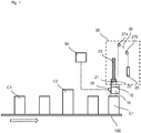
- Fig. 1 schematically shows a conveyor 100 comprising a marking assembly according to an embodiment of the present invention.
- the conveyor 100 which may comprise a conveyor belt or rollers for moving containers C1, C2 (objects) in a conveying direction (arrow in Fig. 1 ) is provided, wherein a print head 10 (marking device) of the marking assembly is configured to provide a marking on an upper surface of the containers C1, C2.
- the print head 10 which may be an ink-jet printing head, comprises printing nozzles, which are facing vertically downwards.
- the print head 10 is attached to a rack or beam 15 extending transversely over the conveyor 100.
- the marking assembly further includes a positioning mechanism 20, which comprises a servo motor (actuator) 21 for moving the print head 10 upwards and downwards along a guide rail 23.
- the guide rail 23 extends in a vertical direction and provides guidance for the beam 15 when moving upwards and downwards.
- a releasing device 22 is provided on the beam 15 and attached on the electric mechanical actuator.
- the servomotor is coupled on the electric mechanical actuator., which is according to the preferred embodiment a solenoid valve.
- the solenoid valve 22 is configured to disengage the pinterhead arm.
- the positioning mechanism 20 further comprises a counterweight 25, which is connected to the beam 15 via a (steel) cable 26.
- the cord 26 extends from an upper portion of the beam 15, is deflected by guiding rollers 27a, 27b and is connected to an upper portion of the counterweight 25.
- the counterweight 25 is conventionally used for balancing the movement of the beam 15, on which the print head 10 is mounted.
- An sensor 30, which may according to the present embodiment a diffused optical sensor or another type of sensor (like, for example, an ultrasound sensor, a radar sensor, or the like), is attached to the print head 10, or, according to another modification, to the beam 15 or another portion of the positioning mechanism 20. In all configurations, the sensor 30 is positioned at an upstream side of the print head 10 and in proximity thereto.
- the sensor 30 is configured to scan an area in front of the print head 10 so that the sensor 30 may detect a container C1, C2 approaching the print head 10. If the distance obtained by the sensor 30 is within a predetermined range or on a predetermined position, the container C1 may pass below the print head 10, which again provides a marking on an upper surface of the container C1. Under these circumstances, a control unit 50 of the marking assembly determines that no repositioning of the beam 15 carrying the print head 10 is required.
- the control unit 50 is in the present case a centralized control unit provided for example on the printing head 10 or on any portion of the positioning mechanism 20, like on the servo motor 21.
- the control unit may be a main control unit of the conveyor 100.
- the control unit 50 may also be a decentralized control unit.
- the predetermined range/ position is either entered manually by an operator or obtained by a corresponding sensor (not shown), like a laser sensor, located in the conveyor 100 at an upstream position of the print head 10.
- Fig. 1 provides a configuration, wherein a plurality of containers C1 is forwarded by the conveyor 100.
- the containers C1 have substantially the same height so that a printing operation may be performed without repositioning the print head 10.
- the print head 10 is usually repositioned on the basis of the predetermined position obtained or entered for a newly arriving container so that a marking may also be provided on an upper portion of the container C2.
- the container C2 having an increased height in comparison to the previous container C1 may approach the print head 10 which is still at a height position for printing an upper surface of a container C1 having a lower height.
- the sensor 30 detects the container C2 and sends a signal to the control unit 50. Since the print head 10 is in a position which is not within the predetermined range and which would lead to a collision with an upper portion of the container C2, the control unit 50 may choose between two options.
- control unit 50 may according to a first option send a command to the servo motor 21 for elevating the print head 10 in a vertical direction with maximum speed, thereby avoiding a collision with the container C2 having an elevated height.
- the control unit 50 may, however, evaluate that the servo motor 21 is not working properly, in particular if a command is send to the servo motor 21 and the control unit 50 receives no feedback from the servo motor 21.
- the control unit 50 may have detected a power failure or the control unit 50 may receive a signal from the collision sensor 30 that the collision sensor is not working properly. Under these circumstances, the control unit 50 detects a failure, for example due to a power failure or an overcurrent.
- control unit 50 may receive a feedback from the servo motor 50, but evaluates that the maximum speed will not be sufficient to avoid a collision with the approaching container C2.
- control unit 50 evaluates that driving the servo motor 21 will not avoid a collision
- the control unit 50 activates, according to a second option, the release device 22, thereby disengaging the printerhead arm.
- the weight of the counterweight 25 lifts the print head 10 in a vertical direction. Consequently, no additional motor is required, but the movement of the beam 15 supporting the printing head 15 is initiated only on the basis of the weight of the counterweight 25.
- the counterweight 25 moves downwards, until the counterweight reaches a bumper that alleviates the impact of the counterweight.
- control unit 50 is configured to perform either option 1 or option 2, a collision of a container with the print head 10 can be reliably avoided.
Landscapes
- Engineering & Computer Science (AREA)
- Manufacturing & Machinery (AREA)
- Auxiliary Devices For And Details Of Packaging Control (AREA)
- Ink Jet (AREA)
- Dot-Matrix Printers And Others (AREA)
- Labeling Devices (AREA)
- Discharge Of Articles From Conveyors (AREA)
Claims (15)
- Ensemble de marquage, comprenant :un dispositif de marquage (10), en particulier une tête d'impression (10), configuré pour fournir un marquage sur un objet franchissant le dispositif de marquage (10),un mécanisme de positionnement (20), le mécanisme de positionnement comprenant un actionneur (21) pour déplacer le dispositif de marquage (10) dans une direction verticale, le mécanisme de positionnement comprenant en outre un contrepoids (25),un dispositif de libération (22), en particulier une électrovanne, pour libérer l'actionneur (21),un capteur (30), le capteur (30) étant approprié pour détecter un objet, en particulier la hauteur de l'objet, approchant le dispositif de marquage (10), etune unité de commande (50) configurée pour recevoir un signal à partir du capteur (30) et configurée poursoit activer l'actionneur (21) pour déplacer le dispositif de marquage (10) jusqu'à une position élevée avec une vitesse accrue soitactiver le dispositif de libération (22) pour libérer l'actionneur (21), en déplaçant ainsi le dispositif de marquage (10) par le contrepoids (25).
- Ensemble de marquage selon la revendication 1, caractérisé en ce que le capteur (30) est un capteur optique, en particulier un capteur optique diffusé.
- Ensemble de marquage selon l'une quelconque des revendications précédentes, caractérisé en ce que l'actionneur (21) est un servomoteur, en particulier un servomoteur comportant un axe de broche mécanique.
- Ensemble de marquage selon l'une quelconque des revendications précédentes, caractérisé en ce que l'unité de commande (50) est configurée pour activer le dispositif de libération (22), si l'activation de l'actionneur (21) échoue.
- Ensemble de marquage selon l'une quelconque des revendications précédentes, caractérisé en ce que l'unité de commande (50) est configurée pour détecter une panne de courant de sorte que l'unité de commande (50) active le dispositif de libération (22) pour libérer l'actionneur (21), en déplaçant ainsi le dispositif de marquage (10) par le contrepoids (25).
- Ensemble de marquage selon l'une quelconque des revendications précédentes, caractérisé en ce que l'unité de commande (50) est configurée pour détecter une panne du capteur (30) de sorte que l'unité de commande (50) active l'actionneur (21) pour déplacer le dispositif de marquage (10) jusqu'à une position élevée.
- Ensemble de marquage selon l'une quelconque des revendications précédentes, caractérisé en ce que l'unité de commande (50) est configurée pour détecter une panne de l'actionneur (21) de sorte que l'unité de commande (50) active le dispositif de libération (22) pour libérer l'actionneur, en déplaçant ainsi le dispositif de marquage (10) par le contrepoids (25).
- Ensemble de marquage selon l'une quelconque des revendications précédentes, caractérisé en ce que le dispositif de marquage (10) est fourni sur une poutre (15) guidée de manière mobile par un guide vertical (23), dans lequel l'actionneur (21) et/ou le dispositif de libération (22) sont montés sur la poutre (15).
- Ensemble de marquage selon l'une quelconque des revendications précédentes, caractérisé en ce que la vitesse accrue est une vitesse maximale de l'actionneur (21).
- Ensemble de marquage selon l'une quelconque des revendications précédentes, caractérisé en ce que l'unité de commande (50) est une unité de commande centralisée.
- Transporteur (100) comprenant un élément de transport pour transporter des objets et un ensemble de marquage selon l'une quelconque des revendications précédentes.
- Procédé d'ajustement d'une position d'un dispositif de marquage d'un ensemble de marquage, en particulier d'un ensemble de marquage selon l'une quelconque des revendications 1 à 10, le procédé comprenant les étapes de :déplacement d'un objet, en particulier d'un récipient (C1, C2), dans une direction de transport,détection de l'objet (C1, C2) par un capteur (30) fourni sur ou à proximité du dispositif de marquage (10) de l'ensemble de marquage, etdétermination du fait d'activer un actionneur (21) pour déplacer le dispositif de marquage (10) jusqu'à une position élevée avec une vitesse accrue, ou d'activer un dispositif de libération (22) pour libérer l'actionneur (21), élevant ainsi le dispositif de marquage (10) par un contrepoids (25) connecté au dispositif de marquage (10).
- Procédé selon la revendication 12, dans lequel l'activation du dispositif de libération (22) est déterminée, si l'activation de l'actionneur (21) échoue ou si une panne de l'actionneur (21) est détectée.
- Procédé selon la revendication 12 ou 13, dans lequel l'activation du dispositif de libération (22) est déterminée, si une panne de courant est détectée.
- Procédé selon l'une quelconque des revendications 12 à 14, dans lequel l'activation de l'actionneur (21) pour déplacer le dispositif de marquage (10) jusqu'à une position élevée est déterminée, si une panne du capteur (30) est détectée.
Applications Claiming Priority (2)
| Application Number | Priority Date | Filing Date | Title |
|---|---|---|---|
| EP2016080610 | 2016-12-12 | ||
| PCT/EP2017/078589 WO2018108391A1 (fr) | 2016-12-12 | 2017-11-08 | Procédé et ensemble de marquage |
Publications (2)
| Publication Number | Publication Date |
|---|---|
| EP3551467A1 EP3551467A1 (fr) | 2019-10-16 |
| EP3551467B1 true EP3551467B1 (fr) | 2020-12-30 |
Family
ID=60320875
Family Applications (1)
| Application Number | Title | Priority Date | Filing Date |
|---|---|---|---|
| EP17797616.4A Active EP3551467B1 (fr) | 2016-12-12 | 2017-11-08 | Procédé et ensemble de marquage |
Country Status (9)
| Country | Link |
|---|---|
| US (1) | US10737487B2 (fr) |
| EP (1) | EP3551467B1 (fr) |
| CN (1) | CN110072702B (fr) |
| CL (1) | CL2019001491A1 (fr) |
| EA (1) | EA201991177A1 (fr) |
| EC (1) | ECSP19042001A (fr) |
| MA (1) | MA48585B1 (fr) |
| MY (1) | MY195966A (fr) |
| WO (1) | WO2018108391A1 (fr) |
Families Citing this family (3)
| Publication number | Priority date | Publication date | Assignee | Title |
|---|---|---|---|---|
| IT202100008519A1 (it) * | 2021-04-06 | 2022-10-06 | Marcozzi S R L | Macchina di stampa di astucci contenitori di prodotti alimentari |
| CN113524929B (zh) * | 2021-08-08 | 2022-03-18 | 合肥市裕同印刷包装有限公司 | 一种环保包装盒绿色标志印刷系统 |
| WO2023172528A1 (fr) * | 2022-03-07 | 2023-09-14 | Cryovac, Llc | Système et procédé d'impression de paquets |
Family Cites Families (14)
| Publication number | Priority date | Publication date | Assignee | Title |
|---|---|---|---|---|
| DE3112079C2 (de) * | 1981-03-27 | 1983-02-03 | Triumph-Adler Aktiengesellschaft für Büro- und Informationstechnik, 8500 Nürnberg | Vorrichtung zum Abheben des Druckkopfes von der Druckgegenlage |
| DE4131911A1 (de) | 1991-09-25 | 1993-04-08 | Horst Schwede | Bedruckvorrichtung fuer fortlaufend vorwaertsbewegte gegenstaende, insbesondere fuer pakete, eingepackte zeitschriftenstapel oder dergleichen |
| JP2877299B2 (ja) * | 1997-06-06 | 1999-03-31 | 三菱重工業株式会社 | 塗装装置 |
| DE19847062B4 (de) | 1998-10-13 | 2004-03-18 | Dsp-Print-Tec Gmbh | Vorrichtung zur automatischen Anpassung der Höhe einer oberhalb einer Fördereinrichtung angeordneten Druckeinrichtung mit einem Abtaster |
| JP2004001329A (ja) * | 2002-06-03 | 2004-01-08 | Mutoh Ind Ltd | インクジェット記録装置 |
| FR2862563B1 (fr) * | 2003-11-24 | 2007-01-19 | Centre Nat Rech Scient | Robot d'impression numerique grand format en trois dimensions sur une surface fixe et procede d'impression mettant en oeuvre au moins un tel robot |
| WO2006060789A2 (fr) | 2004-12-03 | 2006-06-08 | Fujifilm Dimatix, Inc. | Tetes d'impression et systemes mettant en oeuvre des tetes d'impression |
| CN201077192Y (zh) * | 2007-08-28 | 2008-06-25 | 杭州宏华数码科技股份有限公司 | 带厚度检测装置的地毯喷墨印花机 |
| DE102010008295A1 (de) * | 2010-02-17 | 2011-08-18 | Dieffenbacher System Automation GmbH, 75031 | Vorrichtung und Verfahren zum Bedrucken von Oberflächen von Werkstoffplatten, insbesondere Holzplatten, mit einer mehrfarbigen Abbildung |
| US8353566B2 (en) * | 2010-09-17 | 2013-01-15 | Hewlett-Packard Development Company, L.P. | Print bar lift |
| WO2013046344A1 (fr) | 2011-09-27 | 2013-04-04 | 株式会社伊万里鉄鋼センター | Dispositif d'impression |
| JP2014188930A (ja) * | 2013-03-28 | 2014-10-06 | Seiko Epson Corp | 印刷制御装置および印刷装置ならびに印刷方法 |
| CN106457304B (zh) | 2014-06-17 | 2021-03-02 | 科迪华公司 | 打印系统组件和方法 |
| JP6650256B2 (ja) * | 2015-11-30 | 2020-02-19 | 理想科学工業株式会社 | インクジェット印刷装置 |
-
2017
- 2017-11-08 EP EP17797616.4A patent/EP3551467B1/fr active Active
- 2017-11-08 EA EA201991177A patent/EA201991177A1/ru unknown
- 2017-11-08 US US16/469,095 patent/US10737487B2/en active Active
- 2017-11-08 CN CN201780076746.2A patent/CN110072702B/zh active Active
- 2017-11-08 MY MYPI2019002974A patent/MY195966A/en unknown
- 2017-11-08 WO PCT/EP2017/078589 patent/WO2018108391A1/fr not_active Ceased
- 2017-11-08 MA MA48585A patent/MA48585B1/fr unknown
-
2019
- 2019-05-31 CL CL2019001491A patent/CL2019001491A1/es unknown
- 2019-06-12 EC ECSENADI201942001A patent/ECSP19042001A/es unknown
Non-Patent Citations (1)
| Title |
|---|
| None * |
Also Published As
| Publication number | Publication date |
|---|---|
| WO2018108391A1 (fr) | 2018-06-21 |
| CL2019001491A1 (es) | 2019-08-23 |
| US20200070501A1 (en) | 2020-03-05 |
| EA201991177A1 (ru) | 2019-11-29 |
| MA48585B1 (fr) | 2021-04-30 |
| MA48585A (fr) | 2019-10-16 |
| ECSP19042001A (es) | 2019-06-30 |
| BR112019010948A2 (pt) | 2019-10-01 |
| CN110072702A (zh) | 2019-07-30 |
| CA3043301A1 (fr) | 2018-06-21 |
| CN110072702B (zh) | 2021-03-19 |
| EP3551467A1 (fr) | 2019-10-16 |
| MY195966A (en) | 2023-02-27 |
| US10737487B2 (en) | 2020-08-11 |
Similar Documents
| Publication | Publication Date | Title |
|---|---|---|
| EP3551467B1 (fr) | Procédé et ensemble de marquage | |
| JP5620828B2 (ja) | 印刷装置及び印刷方法 | |
| US20130033544A1 (en) | Device and method for printing surfaces of material panels, especially wood panels, with a multi-colour image | |
| KR100903578B1 (ko) | 잉크헤드의 충돌 보호 장치 및 방법 | |
| JP6633088B2 (ja) | シングルパスインクジェットプリンタ | |
| EP3121017B1 (fr) | Machine pour imprimer simultanément sur deux surfaces parallèles | |
| JP2009248559A (ja) | インクジェット印刷装置 | |
| JP2020075772A (ja) | 印字装置及び印字設備 | |
| KR100880897B1 (ko) | 다축 엔코더조립체를 구비한 마킹장치 및 신호처리방법 | |
| CA3043301C (fr) | Procede et ensemble de marquage | |
| US9090104B2 (en) | Device and method for serial printing of print media | |
| JP4541371B2 (ja) | ロール体搬送装置 | |
| OA19070A (en) | Marking assembly and method. | |
| EA041221B1 (ru) | Система и способ нанесения маркировки | |
| CN116472506A (zh) | 对无人驾驶运输车辆的装载物接纳部上的装载物进行位置改变的方法 | |
| BR112019010948B1 (pt) | Conjunto de marcação, esteira, e método para o ajuste de uma posição de um dispositivo de marcação de um conjunto de marcação | |
| KR101380952B1 (ko) | 프린터 헤드 보호장치 | |
| CN211307966U (zh) | 一种喷墨式数码印刷机用墨车防撞装置 | |
| CN111216458A (zh) | 一种包装喷码装置及其使用方法 | |
| US20240217760A1 (en) | Method and arrangement for loading a driverless transport vehicle for individual products | |
| CN211307967U (zh) | 一种平板打印机防撞装置 | |
| JPH0597260A (ja) | 枚葉紙給紙装置 | |
| US20220379625A1 (en) | Liquid-printing apparatus | |
| CN216300560U (zh) | 一种高速在线喷码装置 | |
| US7815283B2 (en) | Printer with a movable carriage |
Legal Events
| Date | Code | Title | Description |
|---|---|---|---|
| STAA | Information on the status of an ep patent application or granted ep patent |
Free format text: STATUS: UNKNOWN |
|
| STAA | Information on the status of an ep patent application or granted ep patent |
Free format text: STATUS: THE INTERNATIONAL PUBLICATION HAS BEEN MADE |
|
| PUAI | Public reference made under article 153(3) epc to a published international application that has entered the european phase |
Free format text: ORIGINAL CODE: 0009012 |
|
| STAA | Information on the status of an ep patent application or granted ep patent |
Free format text: STATUS: REQUEST FOR EXAMINATION WAS MADE |
|
| 17P | Request for examination filed |
Effective date: 20190611 |
|
| AK | Designated contracting states |
Kind code of ref document: A1 Designated state(s): AL AT BE BG CH CY CZ DE DK EE ES FI FR GB GR HR HU IE IS IT LI LT LU LV MC MK MT NL NO PL PT RO RS SE SI SK SM TR |
|
| AX | Request for extension of the european patent |
Extension state: BA ME |
|
| DAX | Request for extension of the european patent (deleted) | ||
| RAV | Requested validation state of the european patent: fee paid |
Extension state: MA Effective date: 20190611 |
|
| REG | Reference to a national code |
Ref country code: DE Ref legal event code: R079 Ref document number: 602017030593 Country of ref document: DE Free format text: PREVIOUS MAIN CLASS: B41J0025304000 Ipc: B41J0003280000 |
|
| GRAP | Despatch of communication of intention to grant a patent |
Free format text: ORIGINAL CODE: EPIDOSNIGR1 |
|
| STAA | Information on the status of an ep patent application or granted ep patent |
Free format text: STATUS: GRANT OF PATENT IS INTENDED |
|
| RIC1 | Information provided on ipc code assigned before grant |
Ipc: B41J 3/28 20060101AFI20200525BHEP Ipc: B41J 25/304 20060101ALI20200525BHEP Ipc: B41J 3/407 20060101ALI20200525BHEP |
|
| INTG | Intention to grant announced |
Effective date: 20200618 |
|
| GRAJ | Information related to disapproval of communication of intention to grant by the applicant or resumption of examination proceedings by the epo deleted |
Free format text: ORIGINAL CODE: EPIDOSDIGR1 |
|
| STAA | Information on the status of an ep patent application or granted ep patent |
Free format text: STATUS: REQUEST FOR EXAMINATION WAS MADE |
|
| RAP1 | Party data changed (applicant data changed or rights of an application transferred) |
Owner name: SICPA HOLDING SA |
|
| INTC | Intention to grant announced (deleted) | ||
| GRAR | Information related to intention to grant a patent recorded |
Free format text: ORIGINAL CODE: EPIDOSNIGR71 |
|
| GRAS | Grant fee paid |
Free format text: ORIGINAL CODE: EPIDOSNIGR3 |
|
| STAA | Information on the status of an ep patent application or granted ep patent |
Free format text: STATUS: GRANT OF PATENT IS INTENDED |
|
| INTG | Intention to grant announced |
Effective date: 20201007 |
|
| GRAA | (expected) grant |
Free format text: ORIGINAL CODE: 0009210 |
|
| STAA | Information on the status of an ep patent application or granted ep patent |
Free format text: STATUS: THE PATENT HAS BEEN GRANTED |
|
| AK | Designated contracting states |
Kind code of ref document: B1 Designated state(s): AL AT BE BG CH CY CZ DE DK EE ES FI FR GB GR HR HU IE IS IT LI LT LU LV MC MK MT NL NO PL PT RO RS SE SI SK SM TR |
|
| REG | Reference to a national code |
Ref country code: GB Ref legal event code: FG4D |
|
| REG | Reference to a national code |
Ref country code: DE Ref legal event code: R096 Ref document number: 602017030593 Country of ref document: DE |
|
| REG | Reference to a national code |
Ref country code: AT Ref legal event code: REF Ref document number: 1349546 Country of ref document: AT Kind code of ref document: T Effective date: 20210115 |
|
| REG | Reference to a national code |
Ref country code: IE Ref legal event code: FG4D |
|
| PG25 | Lapsed in a contracting state [announced via postgrant information from national office to epo] |
Ref country code: NO Free format text: LAPSE BECAUSE OF FAILURE TO SUBMIT A TRANSLATION OF THE DESCRIPTION OR TO PAY THE FEE WITHIN THE PRESCRIBED TIME-LIMIT Effective date: 20210330 Ref country code: FI Free format text: LAPSE BECAUSE OF FAILURE TO SUBMIT A TRANSLATION OF THE DESCRIPTION OR TO PAY THE FEE WITHIN THE PRESCRIBED TIME-LIMIT Effective date: 20201230 Ref country code: RS Free format text: LAPSE BECAUSE OF FAILURE TO SUBMIT A TRANSLATION OF THE DESCRIPTION OR TO PAY THE FEE WITHIN THE PRESCRIBED TIME-LIMIT Effective date: 20201230 |
|
| REG | Reference to a national code |
Ref country code: MA Ref legal event code: VAGR Ref document number: 48585 Country of ref document: MA Kind code of ref document: B1 |
|
| REG | Reference to a national code |
Ref country code: AT Ref legal event code: MK05 Ref document number: 1349546 Country of ref document: AT Kind code of ref document: T Effective date: 20201230 |
|
| PG25 | Lapsed in a contracting state [announced via postgrant information from national office to epo] |
Ref country code: BG Free format text: LAPSE BECAUSE OF FAILURE TO SUBMIT A TRANSLATION OF THE DESCRIPTION OR TO PAY THE FEE WITHIN THE PRESCRIBED TIME-LIMIT Effective date: 20210330 Ref country code: SE Free format text: LAPSE BECAUSE OF FAILURE TO SUBMIT A TRANSLATION OF THE DESCRIPTION OR TO PAY THE FEE WITHIN THE PRESCRIBED TIME-LIMIT Effective date: 20201230 Ref country code: LV Free format text: LAPSE BECAUSE OF FAILURE TO SUBMIT A TRANSLATION OF THE DESCRIPTION OR TO PAY THE FEE WITHIN THE PRESCRIBED TIME-LIMIT Effective date: 20201230 |
|
| REG | Reference to a national code |
Ref country code: NL Ref legal event code: MP Effective date: 20201230 |
|
| PG25 | Lapsed in a contracting state [announced via postgrant information from national office to epo] |
Ref country code: HR Free format text: LAPSE BECAUSE OF FAILURE TO SUBMIT A TRANSLATION OF THE DESCRIPTION OR TO PAY THE FEE WITHIN THE PRESCRIBED TIME-LIMIT Effective date: 20201230 |
|
| REG | Reference to a national code |
Ref country code: LT Ref legal event code: MG9D |
|
| PG25 | Lapsed in a contracting state [announced via postgrant information from national office to epo] |
Ref country code: RO Free format text: LAPSE BECAUSE OF FAILURE TO SUBMIT A TRANSLATION OF THE DESCRIPTION OR TO PAY THE FEE WITHIN THE PRESCRIBED TIME-LIMIT Effective date: 20201230 Ref country code: PT Free format text: LAPSE BECAUSE OF FAILURE TO SUBMIT A TRANSLATION OF THE DESCRIPTION OR TO PAY THE FEE WITHIN THE PRESCRIBED TIME-LIMIT Effective date: 20210430 Ref country code: SK Free format text: LAPSE BECAUSE OF FAILURE TO SUBMIT A TRANSLATION OF THE DESCRIPTION OR TO PAY THE FEE WITHIN THE PRESCRIBED TIME-LIMIT Effective date: 20201230 Ref country code: LT Free format text: LAPSE BECAUSE OF FAILURE TO SUBMIT A TRANSLATION OF THE DESCRIPTION OR TO PAY THE FEE WITHIN THE PRESCRIBED TIME-LIMIT Effective date: 20201230 Ref country code: CZ Free format text: LAPSE BECAUSE OF FAILURE TO SUBMIT A TRANSLATION OF THE DESCRIPTION OR TO PAY THE FEE WITHIN THE PRESCRIBED TIME-LIMIT Effective date: 20201230 Ref country code: EE Free format text: LAPSE BECAUSE OF FAILURE TO SUBMIT A TRANSLATION OF THE DESCRIPTION OR TO PAY THE FEE WITHIN THE PRESCRIBED TIME-LIMIT Effective date: 20201230 |
|
| PG25 | Lapsed in a contracting state [announced via postgrant information from national office to epo] |
Ref country code: AT Free format text: LAPSE BECAUSE OF FAILURE TO SUBMIT A TRANSLATION OF THE DESCRIPTION OR TO PAY THE FEE WITHIN THE PRESCRIBED TIME-LIMIT Effective date: 20201230 Ref country code: PL Free format text: LAPSE BECAUSE OF FAILURE TO SUBMIT A TRANSLATION OF THE DESCRIPTION OR TO PAY THE FEE WITHIN THE PRESCRIBED TIME-LIMIT Effective date: 20201230 |
|
| PG25 | Lapsed in a contracting state [announced via postgrant information from national office to epo] |
Ref country code: IS Free format text: LAPSE BECAUSE OF FAILURE TO SUBMIT A TRANSLATION OF THE DESCRIPTION OR TO PAY THE FEE WITHIN THE PRESCRIBED TIME-LIMIT Effective date: 20210430 |
|
| REG | Reference to a national code |
Ref country code: DE Ref legal event code: R097 Ref document number: 602017030593 Country of ref document: DE |
|
| PG25 | Lapsed in a contracting state [announced via postgrant information from national office to epo] |
Ref country code: AL Free format text: LAPSE BECAUSE OF FAILURE TO SUBMIT A TRANSLATION OF THE DESCRIPTION OR TO PAY THE FEE WITHIN THE PRESCRIBED TIME-LIMIT Effective date: 20201230 |
|
| PLBE | No opposition filed within time limit |
Free format text: ORIGINAL CODE: 0009261 |
|
| STAA | Information on the status of an ep patent application or granted ep patent |
Free format text: STATUS: NO OPPOSITION FILED WITHIN TIME LIMIT |
|
| PG25 | Lapsed in a contracting state [announced via postgrant information from national office to epo] |
Ref country code: DK Free format text: LAPSE BECAUSE OF FAILURE TO SUBMIT A TRANSLATION OF THE DESCRIPTION OR TO PAY THE FEE WITHIN THE PRESCRIBED TIME-LIMIT Effective date: 20201230 |
|
| 26N | No opposition filed |
Effective date: 20211001 |
|
| PG25 | Lapsed in a contracting state [announced via postgrant information from national office to epo] |
Ref country code: ES Free format text: LAPSE BECAUSE OF FAILURE TO SUBMIT A TRANSLATION OF THE DESCRIPTION OR TO PAY THE FEE WITHIN THE PRESCRIBED TIME-LIMIT Effective date: 20201230 |
|
| PG25 | Lapsed in a contracting state [announced via postgrant information from national office to epo] |
Ref country code: SI Free format text: LAPSE BECAUSE OF FAILURE TO SUBMIT A TRANSLATION OF THE DESCRIPTION OR TO PAY THE FEE WITHIN THE PRESCRIBED TIME-LIMIT Effective date: 20201230 |
|
| PG25 | Lapsed in a contracting state [announced via postgrant information from national office to epo] |
Ref country code: IS Free format text: LAPSE BECAUSE OF FAILURE TO SUBMIT A TRANSLATION OF THE DESCRIPTION OR TO PAY THE FEE WITHIN THE PRESCRIBED TIME-LIMIT Effective date: 20210430 |
|
| PG25 | Lapsed in a contracting state [announced via postgrant information from national office to epo] |
Ref country code: MC Free format text: LAPSE BECAUSE OF FAILURE TO SUBMIT A TRANSLATION OF THE DESCRIPTION OR TO PAY THE FEE WITHIN THE PRESCRIBED TIME-LIMIT Effective date: 20201230 |
|
| PG25 | Lapsed in a contracting state [announced via postgrant information from national office to epo] |
Ref country code: LU Free format text: LAPSE BECAUSE OF NON-PAYMENT OF DUE FEES Effective date: 20211108 Ref country code: BE Free format text: LAPSE BECAUSE OF NON-PAYMENT OF DUE FEES Effective date: 20211130 |
|
| REG | Reference to a national code |
Ref country code: BE Ref legal event code: MM Effective date: 20211130 |
|
| PG25 | Lapsed in a contracting state [announced via postgrant information from national office to epo] |
Ref country code: IE Free format text: LAPSE BECAUSE OF NON-PAYMENT OF DUE FEES Effective date: 20211108 |
|
| P01 | Opt-out of the competence of the unified patent court (upc) registered |
Effective date: 20230523 |
|
| PG25 | Lapsed in a contracting state [announced via postgrant information from national office to epo] |
Ref country code: NL Free format text: LAPSE BECAUSE OF NON-PAYMENT OF DUE FEES Effective date: 20201230 Ref country code: CY Free format text: LAPSE BECAUSE OF FAILURE TO SUBMIT A TRANSLATION OF THE DESCRIPTION OR TO PAY THE FEE WITHIN THE PRESCRIBED TIME-LIMIT Effective date: 20201230 |
|
| PG25 | Lapsed in a contracting state [announced via postgrant information from national office to epo] |
Ref country code: SM Free format text: LAPSE BECAUSE OF FAILURE TO SUBMIT A TRANSLATION OF THE DESCRIPTION OR TO PAY THE FEE WITHIN THE PRESCRIBED TIME-LIMIT Effective date: 20201230 Ref country code: HU Free format text: LAPSE BECAUSE OF FAILURE TO SUBMIT A TRANSLATION OF THE DESCRIPTION OR TO PAY THE FEE WITHIN THE PRESCRIBED TIME-LIMIT; INVALID AB INITIO Effective date: 20171108 Ref country code: GR Free format text: LAPSE BECAUSE OF FAILURE TO SUBMIT A TRANSLATION OF THE DESCRIPTION OR TO PAY THE FEE WITHIN THE PRESCRIBED TIME-LIMIT Effective date: 20201230 |
|
| PG25 | Lapsed in a contracting state [announced via postgrant information from national office to epo] |
Ref country code: MK Free format text: LAPSE BECAUSE OF FAILURE TO SUBMIT A TRANSLATION OF THE DESCRIPTION OR TO PAY THE FEE WITHIN THE PRESCRIBED TIME-LIMIT Effective date: 20201230 |
|
| PG25 | Lapsed in a contracting state [announced via postgrant information from national office to epo] |
Ref country code: MT Free format text: LAPSE BECAUSE OF FAILURE TO SUBMIT A TRANSLATION OF THE DESCRIPTION OR TO PAY THE FEE WITHIN THE PRESCRIBED TIME-LIMIT Effective date: 20201230 |
|
| VSFP | Annual fee paid to validation state [announced via postgrant information from national office to epo] |
Ref country code: MA Payment date: 20231110 Year of fee payment: 7 |
|
| VSFP | Annual fee paid to validation state [announced via postgrant information from national office to epo] |
Ref country code: MA Payment date: 20221110 Year of fee payment: 6 Ref country code: MA Payment date: 20211103 Year of fee payment: 5 |
|
| VSFP | Annual fee paid to validation state [announced via postgrant information from national office to epo] |
Ref country code: MA Payment date: 20241108 Year of fee payment: 8 |
|
| REG | Reference to a national code |
Ref country code: CH Ref legal event code: U11 Free format text: ST27 STATUS EVENT CODE: U-0-0-U10-U11 (AS PROVIDED BY THE NATIONAL OFFICE) Effective date: 20251201 |
|
| PGFP | Annual fee paid to national office [announced via postgrant information from national office to epo] |
Ref country code: DE Payment date: 20251022 Year of fee payment: 9 |
|
| PGFP | Annual fee paid to national office [announced via postgrant information from national office to epo] |
Ref country code: GB Payment date: 20251022 Year of fee payment: 9 |
|
| PGFP | Annual fee paid to national office [announced via postgrant information from national office to epo] |
Ref country code: IT Payment date: 20251022 Year of fee payment: 9 |
|
| PGFP | Annual fee paid to national office [announced via postgrant information from national office to epo] |
Ref country code: FR Payment date: 20251022 Year of fee payment: 9 |
|
| PGFP | Annual fee paid to national office [announced via postgrant information from national office to epo] |
Ref country code: TR Payment date: 20251031 Year of fee payment: 9 |
|
| PGFP | Annual fee paid to national office [announced via postgrant information from national office to epo] |
Ref country code: CH Payment date: 20251201 Year of fee payment: 9 |
|
| VSFP | Annual fee paid to validation state [announced via postgrant information from national office to epo] |
Ref country code: MA Payment date: 20251120 Year of fee payment: 9 |