EP3551884B1 - Elektrohydrodynamische vorrichtung und system mit einer elektrohydrodynamischen vorrichtung - Google Patents
Elektrohydrodynamische vorrichtung und system mit einer elektrohydrodynamischen vorrichtung Download PDFInfo
- Publication number
- EP3551884B1 EP3551884B1 EP17700317.5A EP17700317A EP3551884B1 EP 3551884 B1 EP3551884 B1 EP 3551884B1 EP 17700317 A EP17700317 A EP 17700317A EP 3551884 B1 EP3551884 B1 EP 3551884B1
- Authority
- EP
- European Patent Office
- Prior art keywords
- electrode
- gap
- hydro dynamic
- heat sink
- dynamic apparatus
- Prior art date
- Legal status (The legal status is an assumption and is not a legal conclusion. Google has not performed a legal analysis and makes no representation as to the accuracy of the status listed.)
- Not-in-force
Links
- ZZUFCTLCJUWOSV-UHFFFAOYSA-N furosemide Chemical compound C1=C(Cl)C(S(=O)(=O)N)=CC(C(O)=O)=C1NCC1=CC=CO1 ZZUFCTLCJUWOSV-UHFFFAOYSA-N 0.000 title claims description 31
- XLYOFNOQVPJJNP-UHFFFAOYSA-N water Substances O XLYOFNOQVPJJNP-UHFFFAOYSA-N 0.000 claims description 44
- 238000001816 cooling Methods 0.000 claims description 15
- 230000005684 electric field Effects 0.000 claims description 10
- 230000015556 catabolic process Effects 0.000 claims description 9
- 239000002184 metal Substances 0.000 description 6
- 230000005484 gravity Effects 0.000 description 5
- 238000000151 deposition Methods 0.000 description 3
- 238000003698 laser cutting Methods 0.000 description 3
- 239000004020 conductor Substances 0.000 description 2
- 238000010891 electric arc Methods 0.000 description 2
- 238000005452 bending Methods 0.000 description 1
- 230000015572 biosynthetic process Effects 0.000 description 1
- 238000010276 construction Methods 0.000 description 1
- 238000005520 cutting process Methods 0.000 description 1
- 230000001419 dependent effect Effects 0.000 description 1
- 238000010892 electric spark Methods 0.000 description 1
- 238000004519 manufacturing process Methods 0.000 description 1
- 239000000463 material Substances 0.000 description 1
- 238000003825 pressing Methods 0.000 description 1
- 238000004080 punching Methods 0.000 description 1
- 229910001220 stainless steel Inorganic materials 0.000 description 1
- 239000010935 stainless steel Substances 0.000 description 1
Images


Classifications
-
- F—MECHANICAL ENGINEERING; LIGHTING; HEATING; WEAPONS; BLASTING
- F04—POSITIVE - DISPLACEMENT MACHINES FOR LIQUIDS; PUMPS FOR LIQUIDS OR ELASTIC FLUIDS
- F04B—POSITIVE-DISPLACEMENT MACHINES FOR LIQUIDS; PUMPS
- F04B19/00—Machines or pumps having pertinent characteristics not provided for in, or of interest apart from, groups F04B1/00 - F04B17/00
- F04B19/006—Micropumps
-
- F—MECHANICAL ENGINEERING; LIGHTING; HEATING; WEAPONS; BLASTING
- F04—POSITIVE - DISPLACEMENT MACHINES FOR LIQUIDS; PUMPS FOR LIQUIDS OR ELASTIC FLUIDS
- F04B—POSITIVE-DISPLACEMENT MACHINES FOR LIQUIDS; PUMPS
- F04B37/00—Pumps having pertinent characteristics not provided for in, or of interest apart from, groups F04B25/00 - F04B35/00
-
- F—MECHANICAL ENGINEERING; LIGHTING; HEATING; WEAPONS; BLASTING
- F04—POSITIVE - DISPLACEMENT MACHINES FOR LIQUIDS; PUMPS FOR LIQUIDS OR ELASTIC FLUIDS
- F04B—POSITIVE-DISPLACEMENT MACHINES FOR LIQUIDS; PUMPS
- F04B37/00—Pumps having pertinent characteristics not provided for in, or of interest apart from, groups F04B25/00 - F04B35/00
- F04B37/10—Pumps having pertinent characteristics not provided for in, or of interest apart from, groups F04B25/00 - F04B35/00 for special use
-
- F—MECHANICAL ENGINEERING; LIGHTING; HEATING; WEAPONS; BLASTING
- F04—POSITIVE - DISPLACEMENT MACHINES FOR LIQUIDS; PUMPS FOR LIQUIDS OR ELASTIC FLUIDS
- F04B—POSITIVE-DISPLACEMENT MACHINES FOR LIQUIDS; PUMPS
- F04B39/00—Component parts, details, or accessories, of pumps or pumping systems specially adapted for elastic fluids, not otherwise provided for in, or of interest apart from, groups F04B25/00 - F04B37/00
- F04B39/06—Cooling; Heating; Prevention of freezing
-
- F—MECHANICAL ENGINEERING; LIGHTING; HEATING; WEAPONS; BLASTING
- F28—HEAT EXCHANGE IN GENERAL
- F28F—DETAILS OF HEAT-EXCHANGE AND HEAT-TRANSFER APPARATUS, OF GENERAL APPLICATION
- F28F13/00—Arrangements for modifying heat-transfer, e.g. increasing, decreasing
- F28F13/06—Arrangements for modifying heat-transfer, e.g. increasing, decreasing by affecting the pattern of flow of the heat-exchange media
-
- H—ELECTRICITY
- H02—GENERATION; CONVERSION OR DISTRIBUTION OF ELECTRIC POWER
- H02K—DYNAMO-ELECTRIC MACHINES
- H02K44/00—Machines in which the dynamo-electric interaction between a plasma or flow of conductive liquid or of fluid-borne conductive or magnetic particles and a coil system or magnetic field converts energy of mass flow into electrical energy or vice versa
- H02K44/02—Electrodynamic pumps
- H02K44/04—Conduction pumps
Definitions
- the invention relates to an electro hydro dynamic, EHD, apparatus and to a system comprising an electro hydro dynamic, EHD, apparatus.
- An Electro Hydro Dynamic, EHD, device is configured to generate airflow utilising ionised air.
- a high voltage is applied between two electrodes, which forms an electric field.
- the electric field ionises air.
- the ionised air is drawn towards one of the electrodes and is thus, accelerated.
- the accelerated air passes the one electrode and forms the airflow.
- Such an airflow may be utilised for cooling heat generating equipment.
- an Electro Hydro Dynamic, EHD, cooling device may be referred to.
- US 2016079840 discloses an Electro Hydro Dynamic, EHD, thruster comprising a first set of electrodes, a second set of electrodes, and a supporting structure for supporting the first set of electrodes and the second set of electrodes.
- the EHD thruster is configured to generate airflow of ionised air for cooling a heat sink. It is proposed that the EHD thruster is utilised to move air across the surface of the heat sink instead of utilising a rotating fan.
- the EHD thruster has no moving or rotating parts. A reliable and silent cooling mechanism is achieved for providing high capacity cooling of the heat sink. By keeping the EHD thruster electrically isolated from the heat sink, the risk of an accident is reduced.
- the heat sink may be thermally coupled to a power amplifier of a Remote Radio Unit, RRU.
- an EHD apparatus is dependent on a correct distance between the two electrodes in order to properly ionise air. If the EHD apparatus is used in an environment where water droplets may be present, such droplets may deposit on one or both electrodes reducing the electrical distance there between causing an electrical breakdown, which may take the form of an electric spark or an electric arc.
- an electro hydro dynamic, EHD, apparatus as defined in claim 1 comprising a first electrode and a second electrode, wherein the second electrode is arranged above the first electrode at a predetermined distance for generating an airflow.
- the second electrode comprises at least one electrode element.
- the at least one electrode element comprises a gap extending along a length of the at least one electrode element for capillary conducting water droplets along the at least one electrode element.
- the at least one electrode element of the second electrode comprises a gap extending along a length of the at least one electrode element for capillary conducting water droplets along the at least one electrode element, water droplets are prevented from depositing on the at least one electrode element in a manner which would shorten an electrical distance between the first and second electrodes. Instead, water is conducted in the gap along the at least one electrode element, to an area of the second electrode where the water may be drained from the second electrode without causing electrical breakdown. As a result, the above mentioned object is achieved. Moreover, the EHD apparatus is thus, suited for use in humid environments where water droplets may form on the second electrode, or in environments where water droplets may be present, such as outdoors.
- the electro hydro dynamic, EHD, apparatus is configured for generating the airflow utilising ionised air between the first and second electrodes.
- a high voltage is applied between the first and second electrodes, forming an electric field between the two electrodes.
- the electric field ionises the air in between the electrodes.
- the ionised air is drawn towards the second electrode and thus, accelerates air in between the two electrodes.
- the accelerated air passes the second electrode and forms the airflow.
- the first and second electrodes may comprise a conductive material, such as e.g. a metal.
- the at least one electrode element may comprise a through slit forming the gap. In this manner, the gap may be easily manufactured, e.g. in a laser cutting operation.
- the at least one electrode element may comprise two separate members forming there between the gap.
- the gap may be provided by positioning two separate members at a suitable distance from each other.
- the first electrode and the second electrode may extend along a first direction and the at least one electrode element may extend along a second direction across the first direction and wherein at least a portion of the gap may have a width in the first direction within a range of 0.1 - 0.5 mm. In this manner, a gap width suitable for providing capillary action on water droplets may be provided.
- the gap may widen towards at least one end of the gap.
- the capillary action on the water in the gap may be reduced at the wide end of the gap.
- water may be drained from the wide end of the gap.
- water droplets may continuously or intermittently be drawn into the gap by the capillary action of the gap, and the water droplets may continuously or intermittently be drained at the wide end of the gap.
- the wide end of the gap may suitably be arranged at a distance from the first electrode such that the electrical distance between the first and second electrodes is not shortened by the water being drained from the wide end of the gap.
- the at least one electrode element may comprise at least a first electrode portion configured to be arranged at a first angle to a horizontal plane. In this manner, gravity may assist water in the gap to flow along the first electrode portion in the gap.
- the at least one electrode element may comprise a first electrode portion and a second electrode portion, and wherein the first and second electrode portions may be arranged at an obtuse angle to each other with a vertex of the obtuse angle pointing away from the first electrode. In this manner, gravity may assist water in the gap to flow along also the second electrode portion in the gap.
- the provision of the first and second electrode portions being arranged at the obtuse angle provide for the first and second electrode portions being symmetrically arranged in relation to the first electrode.
- the gap may widen towards a low end of the gap. In this manner, gravity may assist water in the gap to flow towards the wide end of the gap where the water is drained from the gap.
- the first electrode may comprise at least one protrusion extending in a direction towards the second electrode, setting a predetermined distance between the first and second electrodes for forming an electric field between the first and second electrodes configured to generate the airflow utilising ionised air.
- the at least one protrusion may provide a well-defined portion of the first electrode where the electric field between the first and second electrodes will have its highest value.
- the second electrode may comprise a first electrode element and a second electrode element, wherein the first and second electrode elements may be arranged with an interspace there between for permitting the airflow to pass through the second electrode.
- the electric field between the first and second electrodes may have the highest value at each of the first and second electrode elements for ionising air to generate the airflow during use of the EHD apparatus.
- the generated airflow may pass the second electrode through the interspace between the first and second electrode elements.
- the object is achieved by a system comprising heat generating electronic components, a heat sink thermally connected to the heat generating electronic components, and an electro hydro dynamic, EHD, apparatus according to any one of aspects and/or embodiments discussed herein arranged to generate an airflow in a flow direction along and/or through the heat sink.
- the EHD apparatus directly cools the heat sink and indirectly cools the heat generating electronic components.
- the EHD apparatus forms an electoral hydrodynamic, EHD, cooling device of the system.
- the at least one electrode element of the second electrode comprises a gap extending along a length of the at least one electrode element, as discussed above, water droplets are prevented from depositing on the at least one electrode element.
- the system is suited for outdoor use where water droplets may be present. As a result, the above mentioned object is achieved.
- the heat generating electronic components may for instance comprise a power amplifier of a Remote Radio Unit, RRU. Since the heat sink is thermally coupled to the power amplifier, the power amplifier may be indirectly cooled by the EHD apparatus.
- RRU Remote Radio Unit
- the heat sink may comprise a first heat sink part and a second heat sink part, and a compartment for holding the EHD apparatus for providing a push airflow in the flow direction along and/or through the first heat sink part and a pull airflow along and/or through the second heat sink part.
- the airflow on both sides of the EHD apparatus may be utilised for providing the airflow a long and/or through both the first and second heat sink parts.
- the EHD apparatus may be open in the flow direction for enabling natural convection cooling of the heat sink. In this manner, cooling of the heat sink by natural convection is not obstructed by the EHD apparatus when the EHD apparatus is switched off.
- Figs. 1a and 1b illustrate schematically cross sections through an electro hydro dynamic, EHD, apparatus 2'.
- a high voltage is applied over a first electrode 4' and a second electrode 6'.
- the electrical distance D between the first and second electrodes 4', 6' is the shortest distance between the first and second electrodes 4', 6'.
- the electrical distance D should be as short as possible in relation to the applied voltage between the first and second electrodes 4', 6' without causing electrical breakdown.
- a water droplet 5 hanging from a lower side of the second electrode 6' may shorten the original electrical distance D to a different electrical distance D' short enough to cause electrical breakdown, as indicated with the electric arc 7 in Fig. 1b . Accordingly, the forming of water droplets in critical areas of the upper electrode is to be avoided.
- the inventor has realised that capillary action may be utilised for preventing formation of water droplets on the upper electrode large enough for, and/or in places, causing electrical breakdown in the EHD apparatus.
- the use of capillary action is a cost efficient and reliable way of preventing the forming of water droplets on the electrode of the EHD apparatus.
- Figs. 2a - 2d illustrate an example of an electro hydro dynamic, EHD, apparatus 2.
- Fig. 2a illustrates a view of the EHD apparatus 2
- Fig. 2b illustrates a partial enlargement of the EHD apparatus 2
- Fig. 2c illustrates a view along lines C - C in Fig. 2a
- Fig. 2d illustrates a partial enlargement of a second electrode 6 of the EHD apparatus 2.
- the EHD apparatus 2 comprises a first electrode 4 and the second electrode 6.
- the first and second electrodes 4, 6 may be arranged in a holding structure, not shown.
- the holding structure electrically isolates the first electrode 4 from the second electrode 6.
- the second electrode 6 is arranged above the first electrode 4.
- the first electrode 4 may be considered a high voltage emitter, and the second electrode 6 may form a grounded collector grid.
- the voltage applied over the first and second electrodes 4, 6 is very close to the voltage resulting in electrical breakdown between the first and second electrodes 4, 6.
- the high voltage forms an electric field which ionises the air in between the first and second electrodes 4, 6, which generates an airflow in a direction from the first electrode 4 towards the second electrode 6.
- the voltage between the first and second electrodes 4, 6 may be within a range of 7 - 15 kV.
- the second electrode 6 comprises at least one electrode element 10, 12.
- the second electrode 6 may comprise a first electrode element 10 and a second electrode element 12. More specifically, the second electrode may comprise a number of electrode elements 10, 12, 13.
- the electrode elements 10, 12, 13 are arranged with an interspace 16 between pairs of the electrode elements 10, 12, 13.
- the airflow is permitted to pass through the interspaces 16.
- water droplets falling from above the second electrode 6 may fall through the interspaces 16, and the EHD apparatus 2 without affecting the function of the EHD apparatus 2.
- the at least one electrode element 10, 12, and suitably each electrode element of the number of electrode elements 10, 12, 13, comprises a gap 18 extending along a length of the relevant electrode element 10, 12, 13.
- Water droplets depositing on the relevant electrode element 10, 12, 13 are drawn into the gap 18 by capillary action.
- the water droplets may be capillary conducted along the relevant electrode element 10, 12, 13 and electrical breakdown, otherwise caused by the water droplets, may be avoided.
- the gap 18 in each of the electrode elements 10, 12, 13 may be formed by a through slit 20.
- the second electrode 6 may be made from metal. Mentioned purely as an example, the second electrode 6 may be manufactured from sheet metal, such as e.g. stainless steel sheet metal. The sheet metal may have a thickness within a range of 0.3 - 5.0 mm. The second electrode 6 may be formed from sheet metal e.g. by punching, cutting, or laser cutting, and bending or pressing. The slit 20 in each electrode element 10, 12, 13 may e.g. be cut in a laser cutting operation. Similarly, the first electrode 4 may be manufactured from the same type of material and using the same manufacturing methods as the second electrode 6.
- the first electrode 4 and the second electrode 6 extend along a first direction 8.
- the at least one electrode element 10, 12 extends along a second direction 14 across the first direction 8.
- the second direction 14 extends perpendicularly to the first direction 8.
- the second direction 14 may extend at a different angle across the first direction 8, such as at e.g. a 45° angle.
- the width of the gap 18 may be within a range of 0.1 - 0.5 mm. More specifically, at least a portion of the gap 18 may have a width in the first direction 8 within a range of 0.1 - 0.5 mm. According to some embodiments the gap 18 may have a width within a range of 0.2 - 0.3 mm.
- the gap 18 widens towards one end 32 of the gap 18.
- the one end 32 of the gap 18 may be one or more millimetres wide.
- the one end 32 of the gap 18 may also be referred to as the wide end 32 of the gap 18.
- the capillary action on any water in the gap 18 is reduced at the wide end 32 of the gap 18, and water may be drained from the gap 18 at its wide end 32.
- the wide end 32 of the gap 18 may be arranged within the electrode element 10, 12. Alternatively, and as illustrated in Figs. 2b and 2d , the wide end 32 of the gap 18 may be arranged a common portion 33 of the second electrode 6, to which common portion 33 the electrode elements 10, 12 connect.
- Each of the electrode elements 10, 12, 13 comprise a first electrode portion 26 configured to be arranged at a first angle A to a horizontal plane H, when the EHD apparatus 2 is in use.
- gravity may assist water in the gap 18 to flow along the first electrode portion 26 in the gap 18, towards a low end of the gap 18.
- the wide end 32 of the gap 18 may drain the gap 18 from water.
- the gap 18 may simply extend all the way through the common portion 33 thus, forming a drainage opening at a lower end of the second electrode 6.
- the first electrode 4 extends in the first direction 8. Perpendicularly to the first direction 8 an extension of the first electrode 4 is limited, e.g. in the order of the 1 - 10 mm. Thus, the airflow passes the first electrode 4 without being hindered by the first electrode 4 to any larger extent.
- the first electrode 4 comprises one protrusion 24, extending in a direction towards the second electrode 6, for each electrode element 10, 12, 13. Between one protrusions 24 and a corresponding electrode element 10, 12, 13 a predetermined distance is set.
- the predetermined distance suitably forms the electrical distance D between the first and second electrodes 4, 6 of the EHD apparatus 2.
- the electric field between the first and second electrodes 4, 6 has its highest values in positions having the electrical distance D there between. Mentioned purely as an example, the electrical distance D may be e.g. 15 mm.
- the voltage applied between the first and second electrodes 4, 6 may in such case be approximately 15 kV.
- Fig. 3a illustrates schematically a portion of a second electrode 6 as an alternative example.
- Each of the electrode elements 10, 12, 13 comprises two separate members 22, 22' forming there between the gap 18. Again, the gap 18 has a width such that water will be drawn into the gap 18 by capillary action.
- each of the two separate members 22, 22' comprises a rod.
- the separate members 22, 22' are connected to a common portion 33' of the second electrode 6.
- a further common portion may be connected to the opposite ends of the separate members 22, 22'. Interspaces 16 for passage of an airflow are formed between the electrode elements 10, 12, 13.
- Fig. 3b illustrates schematically a portion of a second electrode 6 as another example.
- the electrode elements 10 comprise two separate members 22, 22' forming there between the gap 18.
- the gap 18 has a width such that water will be drawn into the gap 18 by capillary action.
- each of the two separate members 22, 22' comprises a flat member.
- the separate members 22, 22' are connected to a common potion 33' of the second electrode 6.
- Interspaces 16 for passage of an airflow are formed between the electrode elements 10.
- one of the interspaces is indicated adjacent to one of the separate members 22.
- Figs. 4a - 4c illustrate another example of an electro hydro dynamic, EHD, apparatus 2.
- Fig. 4a illustrates a view of the EHD apparatus 2
- Fig. 4b illustrates a partial enlargement of the EHD apparatus 2
- Fig. 4c illustrates a cross section along lines III - III in Fig. 4a .
- These embodiments resemble in much the embodiments of Figs. 2a - 2d . Accordingly, in the following mainly the differences to the embodiments of Figs. 2a - 2d will be discussed.
- the EHD apparatus 2 comprises a first electrode 4 and the second electrode 6 extending along a first direction 8.
- the second electrode 6 comprises at least one electrode element 10, 12, 13.
- the first electrode 4 comprises one protrusion 24, extending in a direction towards the second electrode 6, for each electrode element 10, 12, 13.
- the electrode elements 10, 12, 13 are arranged with an interspace 16 between pairs of the electrode elements 10, 12, 13.
- the at least one electrode element 10, 12 comprises a gap 18 extending along a length of the at least one electrode element 10, 12.
- the at least one electrode element 10, 12 extends along a second direction 14 across the first direction 8.
- each of the electrode elements 10, 12 comprises a first electrode portion 26 which may be arranged at a first angle A to a horizontal plane H, when the EHD apparatus 2 is in use.
- each of the electrode elements 10, 12 comprises a second electrode portion 28 which may be arranged at a second angle B to the horizontal plane H, when the EHD apparatus 2 is in use.
- the first and second electrode portions 26, 28 are arranged at an obtuse angle C to each other with a vertex 30 of the obtuse angle C pointing away from the first electrode 4.
- the first and second electrode portions 26, 28 being arranged in this manner provide for gravity to assist water in the gap 18 to flow along the first and second electrode portions 26, 28 in the gap 18, towards respective low ends of the gap 18.
- the gap 18 may form one gap which extends along both the first and second electrode portions 26, 28.
- each of the first and second electrode portions 26, 28 may be provided with one gap 18, 18'.
- the gap 18 widens towards both ends 32, 32' of the gap 18, if the gap 18 extends along both the first and second electrode portions 26, 28. If each of the first and second portions 26, 28 are provided with one gap 18, 18', one end 32, 32' of each gap 18, 18' widens. The gap 18 widens towards one or both low ends 32, 32'. Thus, the capillary action on any water in the gap 18 is reduced at the low positioned wide end/s 32, 32' of the gap 18, and water may be drained from the gap 18 at its wide end/s 32, 32'.
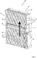
- Fig. 5 Illustrates an example of a system 50 comprising an electro hydro dynamic, EHD, apparatus 2.
- the system 50 comprising heat generating electronic components 52, suitably arranged inside a housing 53.
- a heat sink 54 is thermally connected to the heat generating electronic components 52 and is arranged on an outside of the housing 53.
- the EHD apparatus 2 is an EHD apparatus according to any one of aspects and/or embodiments discussed herein.
- the EHD apparatus 2 is arranged to generate an airflow in a flow direction 55 along and/or through the heat sink 54.
- the flow direction 55 is in an upwardly direction.
- natural convection at the heat sink 54 is complemented by the airflow generated by the EHD apparatus 2.
- the heat sink 54 comprises a large number of fins 57, which provide a large cooling surface to be cooled by the airflow.
- the EHD apparatus 2 cools the heat sink 54, which in turn conducts the heat from the heat generating electronic components 52.
- the heat sink 54 comprises a first heat sink part 56 and a second heat sink part 58, and a compartment 60 for holding the EHD apparatus 2.
- the first heat sink part 56 is arranged above the compartment 60 and the second heat sink part 58 is arranged below the compartment 60.
- the EHD apparatus 2 provides a push airflow in the flow direction 55 along and/or through the first heat sink part 56 and a pull airflow along and/or through the second heat sink part 58.
- the compartment 60 is open at its lower and upper sides to permit the airflow generated by the EHD apparatus 2 to pass through the compartment 60.
- the EHD apparatus 2 and the compartment 60 are open in the flow direction 55 for enabling natural convection cooling of the heat sink 54.
- natural convection is neither obstructed by the EHD apparatus 2, nor by the compartment 60, when the EHD apparatus 2 is switched off.
- the system 50 may for instance be a Remote Radio Unit, RRU, and the heat generating electronic components 52 may for instance comprise a power amplifier.
- the high voltage applied to the first and second electrodes of the EHD apparatus 2 may be generated by electrical components arranged inside the housing 53. Electrical conductors connect such electrical components with the first and second electrodes of the EHD apparatus 2.
- the system 50 is configured for use in environments where water droplets are present, such as e.g. for outdoor use. Due to the provision of the gaps in the second electrode of the EHD apparatus 2, capillary action prevents the forming of water droplets on the second electrode, as discussed above.
- the EHD apparatus 2 may have a length in the first direction 8, see e.g. Figs. 2a and 4a , of approximately 0,3 m and may be supplied with a voltage within a range of 10 - 15 kV. Such an EHD apparatus 2 may provide an airflow within a range of 0.00378 - 0.00566 m 3 /s (corresponding to 3.77 - 5.66 liter/second or to 8 -12 cubic feet/minute). Such an airflow may provide a 10 W/litre air increased cooling capacity over natural convection cooling in the heat sink 54. For instance, depending on the design of the heat sink 54, a heat sink 54 may provide a natural convection cooling capacity of 30 W/litre air. With the EHD apparatus 2 switched on, the cooling capacity may be approximately 40 W/litre air.
- electrode element 10, 12, 13 may comprise more than one gap 18 extending in parallel with each other along the electrode element 10, 12, 13.
Landscapes
- Engineering & Computer Science (AREA)
- Mechanical Engineering (AREA)
- General Engineering & Computer Science (AREA)
- Physics & Mathematics (AREA)
- Thermal Sciences (AREA)
- Power Engineering (AREA)
- Physical Or Chemical Processes And Apparatus (AREA)
- Electrostatic Spraying Apparatus (AREA)
Claims (12)
- Elektrohydrodynamische Vorrichtung (2), umfassend eine erste Elektrode (4) und eine zweite Elektrode (6), wobei die zweite Elektrode (6) in einem vorbestimmten Abstand von der ersten Elektrode angeordnet ist, (4) um einen Luftstrom zu erzeugen, wobei die zweite Elektrode (6) mindestens ein Elektrodenelement (10, 12) umfasst,
dadurch gekennzeichnet, dass das mindestens eine Elektrodenelement (10, 12) einen Spalt (18) umfasst, der sich entlang einer Länge des mindestens einen Elektrodenelements (10, 12) erstreckt, um Wassertröpfchen durch Kapillarwirkung entlang des mindestens einen Elektrodenelements (10, 12) zu leiten, wobei Wasser in dem Spalt entlang des mindestens einen Elektrodenelements zu einem Bereich der zweiten Elektrode geleitet wird, in dem das Wasser aus der zweiten Elektrode abgelassen werden kann, ohne einen elektrischen Durchschlag zu verursachen. - Elektrohydrodynamische Vorrichtung (2) nach Anspruch 1, wobei das wenigstens eine Elektrodenelement (10, 12) einem durchgehenden Schlitz (20) umfasst, der den Spalt (18) ausbildet.
- Elektrohydrodynamische Vorrichtung (2) nach Anspruch 1, wobei das wenigstens eine Elektrodenelement (10, 12) zwei getrennte Elemente (22, 22') umfasst, zwischen denen der Spalt (18) ausgebildet ist.
- Elektrohydrodynamische Vorrichtung (2) nach einem der vorhergehenden Ansprüche, wobei die erste Elektrode (4) und die zweite Elektrode (6) sich entlang einer ersten Richtung (8) erstrecken, und das mindestens ein Elektrodenelement (10, 12) sich entlang einer zweiten Richtung (14) über die erste Richtung (8) hinweg erstreckt, wobei mindestens ein Teil des Spaltes (18) in der ersten Richtung (8) eine Breite in einem Bereich von 0,1-0,5 mm aufweist.
- Elektrohydrodynamische Vorrichtung (2) nach einem der vorhergehenden Ansprüche, wobei der Spalt (18) sich zu mindestens einem Ende (32) des Spaltes (18) hin weitet.
- Elektrohydrodynamische Vorrichtung (2) nach einem der vorhergehenden Ansprüche, wobei das mindestens eine Elektrodenelement (10, 12) einen ersten Elektrodenabschnitt (26) und einen zweiten Elektrodenabschnitt (28) umfasst und wobei der erste und der zweite Elektrodenabschnitt (26, 28) in einem stumpfen Winkel (C) zueinander angeordnet sind, wobei ein Scheitelpunkt (30) des stumpfen Winkels von der ersten Elektrode (4) weg zeigt.
- Elektrohydrodynamische Vorrichtung (2) nach Anspruch 6, wobei der Spalt (18) sich zu einem unteren Ende (32) des Spaltes (18) hin weitet.
- Elektrohydrodynamische Vorrichtung (2) nach einem der vorhergehenden Ansprüche, wobei die erste Elektrode (2) mindestens einen Vorsprung (24, 24') umfasst, der sich in einer Richtung zu der zweiten Elektrode (6) erstreckt, welche einen vorgegebenen Abstand zwischen der ersten und der zweiten Elektrode (4, 6) einstellt, um ein elektrisches Feld zwischen der ersten und der zweiten Elektrode (4, 6) auszubilden, das dafür konfiguriert ist, unter Einsatz von ionisierter Luft den Luftstrom zu erzeugen.
- Elektrohydrodynamische Vorrichtung (2) nach einem der vorhergehenden Ansprüche, wobei die zweite Elektrode ein erstes Elektrodenelement (10) und ein zweites Elektrodenelement (12) umfasst, wobei das erste und das zweite Elektrodenelement (10, 12) mit einem Spalt (16) dazwischen angeordnet sind, um zu ermöglichen, dass der Luftstrom durch die zweite Elektrode (6) strömt.
- System (50), umfassend wärmeerzeugende elektronische Komponenten (52), eine thermisch mit den wärmeerzeugenden elektronischen Komponenten (52) verbundene Wärmesenke (54), und eine elektrohydrodynamische Vorrichtung (2) nach einem der vorhergehenden Ansprüche, angeordnet, einen Luftstrom in einer Strömungsrichtung (55) entlang der Wärmesenke (54) und/oder durch diese hindurch zu erzeugen.
- System nach Anspruch 10, wobei die Wärmesenke (54) ein erstes Wärmesenkenteil (56) und ein zweites Wärmesenkenteil (58) und ein Fach (60) zum Halten der elektrohydrodynamischen Vorrichtung (2) umfasst, um einen Druckluftstrom in der Strömungsrichtung (55) entlang und/oder durch den ersten Wärmesenkenteil (56) und eines Zugluftstroms entlang und/oder durch den zweiten Wärmesenkenteil (58) bereitzustellen.
- System nach Anspruch 11, wobei die elektrohydrodynamischen Vorrichtung (2) in der Strömungsrichtung offen ist (55), um natürliche Konvektionskühlung für die Wärmesenke (54) zu ermöglichen.
Applications Claiming Priority (1)
| Application Number | Priority Date | Filing Date | Title |
|---|---|---|---|
| PCT/EP2017/050301 WO2018127293A1 (en) | 2017-01-09 | 2017-01-09 | Electro hydro dynamic apparatus and system comprising an electro hydro dynamic apparatus |
Publications (2)
| Publication Number | Publication Date |
|---|---|
| EP3551884A1 EP3551884A1 (de) | 2019-10-16 |
| EP3551884B1 true EP3551884B1 (de) | 2020-07-15 |
Family
ID=57796339
Family Applications (1)
| Application Number | Title | Priority Date | Filing Date |
|---|---|---|---|
| EP17700317.5A Not-in-force EP3551884B1 (de) | 2017-01-09 | 2017-01-09 | Elektrohydrodynamische vorrichtung und system mit einer elektrohydrodynamischen vorrichtung |
Country Status (4)
| Country | Link |
|---|---|
| US (1) | US20190331102A1 (de) |
| EP (1) | EP3551884B1 (de) |
| CN (1) | CN109072893B (de) |
| WO (1) | WO2018127293A1 (de) |
Cited By (1)
| Publication number | Priority date | Publication date | Assignee | Title |
|---|---|---|---|---|
| WO2023049152A1 (en) * | 2021-09-21 | 2023-03-30 | Worcester Polytechnic Institute | Electrohydrodynamic drying of moist porous materials |
Families Citing this family (2)
| Publication number | Priority date | Publication date | Assignee | Title |
|---|---|---|---|---|
| WO2023009086A2 (en) * | 2021-07-28 | 2023-02-02 | Repg Enerji Sistemleri Sanayi Ve Ticaret Anonim Sirketi | An air thrust system |
| CN118017795B (zh) * | 2024-04-08 | 2024-06-25 | 浙江大学 | 感应式电磁泵 |
Family Cites Families (12)
| Publication number | Priority date | Publication date | Assignee | Title |
|---|---|---|---|---|
| JPS63259396A (ja) * | 1986-03-31 | 1988-10-26 | Agency Of Ind Science & Technol | 電場によるジェット発生装置における電極 |
| DE10360220A1 (de) * | 2003-12-20 | 2005-07-21 | Steag Microparts Gmbh | Mikrostrukturierte Anordnung zur blasenfreien Befüllung zumindest eines Systems zur Ableitung von Flüssigkeiten, Vorrichtung mit einer solchen Anordnung und Befüllungsverfahren |
| CN101107444B (zh) * | 2005-01-24 | 2011-06-15 | 文蒂瓦公司 | 电流体动力泵和包括电流体动力泵的冷却装置 |
| US8172547B2 (en) * | 2008-01-31 | 2012-05-08 | The Boeing Company | Dielectric barrier discharge pump apparatus and method |
| CN101252822B (zh) * | 2008-04-11 | 2010-09-15 | 北京工业大学 | 一种ehd强化的微型散热装置 |
| US8466624B2 (en) * | 2008-09-03 | 2013-06-18 | Tessera, Inc. | Electrohydrodynamic fluid accelerator device with collector electrode exhibiting curved leading edge profile |
| EP2163514A1 (de) * | 2008-09-11 | 2010-03-17 | E&Sa Project AG | Technologie zur Herstellung von Treibstoffgas und Elektroenergie aus Wasser |
| US20110174468A1 (en) * | 2009-08-11 | 2011-07-21 | Ventiva, Inc. | Ozone reducing heat sink having contoured fins |
| WO2011149667A1 (en) * | 2010-05-26 | 2011-12-01 | Tessera, Inc. | Electrohydrodynamic fluid mover techniques for thin, low-profile or high-aspect-ratio electronic devices |
| US20110308775A1 (en) * | 2010-06-21 | 2011-12-22 | Tessera, Inc. | Electrohydrodynamic device with flow heated ozone reducing material |
| US10871296B2 (en) * | 2013-09-18 | 2020-12-22 | Mitsubishi Electric Corporation | Humidifier and air-conditioning apparatus including humidifier |
| WO2016041581A1 (en) | 2014-09-16 | 2016-03-24 | Huawei Technologies Co., Ltd | Method, device and system for cooling |
-
2017
- 2017-01-09 EP EP17700317.5A patent/EP3551884B1/de not_active Not-in-force
- 2017-01-09 WO PCT/EP2017/050301 patent/WO2018127293A1/en not_active Ceased
- 2017-01-09 CN CN201780025679.1A patent/CN109072893B/zh active Active
-
2019
- 2019-07-09 US US16/506,652 patent/US20190331102A1/en not_active Abandoned
Non-Patent Citations (1)
| Title |
|---|
| None * |
Cited By (1)
| Publication number | Priority date | Publication date | Assignee | Title |
|---|---|---|---|---|
| WO2023049152A1 (en) * | 2021-09-21 | 2023-03-30 | Worcester Polytechnic Institute | Electrohydrodynamic drying of moist porous materials |
Also Published As
| Publication number | Publication date |
|---|---|
| US20190331102A1 (en) | 2019-10-31 |
| CN109072893B (zh) | 2019-11-29 |
| EP3551884A1 (de) | 2019-10-16 |
| CN109072893A (zh) | 2018-12-21 |
| WO2018127293A1 (en) | 2018-07-12 |
Similar Documents
| Publication | Publication Date | Title |
|---|---|---|
| US20190331102A1 (en) | Electro hydro dynamic apparatus and system comprising an electro hydro dynamic apparatus | |
| US7661468B2 (en) | Electro-hydrodynamic gas flow cooling system | |
| US8611088B2 (en) | Mechanical heat pump for an electrical housing | |
| EP2474782B1 (de) | Ionenwind-Kühleinheit und LED-Beleuchtungseinheit mit dieser Kühleinheit | |
| US8466624B2 (en) | Electrohydrodynamic fluid accelerator device with collector electrode exhibiting curved leading edge profile | |
| CN101998804B (zh) | 离子风散热装置 | |
| US20110036552A1 (en) | Heatsink having one or more ozone catalyzing fins | |
| WO2011058411A2 (en) | Cooling of electronic components using self-propelled ionic wind | |
| CN105723820B (zh) | 散热方法、设备和系统 | |
| EP1939904A2 (de) | Druckluftschalter mit Vorrichtung zur ARC-Unterdrückung | |
| EP3863047B1 (de) | Kühlvorrichtung | |
| US20110139401A1 (en) | Ionic wind heat sink | |
| ES2726228B2 (es) | Disipador de Calor Electro-Hidro-Dinámico | |
| US20080060794A1 (en) | Heat sink device generating an ionic wind | |
| JP2011511997A (ja) | 強化された静電放電のための補助電極 | |
| JP2025085591A (ja) | エネルギー貯蔵コンバータ及び放熱システム | |
| WO1994012282A1 (en) | Cooling method and apparatus | |
| JP2010239165A (ja) | プラズマシンセティックジェットを用いた冷却装置 | |
| JP4298645B2 (ja) | 冷却手段を備えた高圧設備の区間 | |
| JP2008078260A (ja) | イオン風を発生させるヒートシンク装置 | |
| JP5453125B2 (ja) | イオン発生装置 | |
| CN105637604A (zh) | 安装设备中的冷却设备的板堆 | |
| CN107734938B (zh) | 一种散热结构 | |
| BR0108813A (pt) | Comutador e método para sua fabricação | |
| CN220830631U (zh) | 一种散热结构及电子设备 |
Legal Events
| Date | Code | Title | Description |
|---|---|---|---|
| STAA | Information on the status of an ep patent application or granted ep patent |
Free format text: STATUS: UNKNOWN |
|
| STAA | Information on the status of an ep patent application or granted ep patent |
Free format text: STATUS: THE INTERNATIONAL PUBLICATION HAS BEEN MADE |
|
| PUAI | Public reference made under article 153(3) epc to a published international application that has entered the european phase |
Free format text: ORIGINAL CODE: 0009012 |
|
| STAA | Information on the status of an ep patent application or granted ep patent |
Free format text: STATUS: REQUEST FOR EXAMINATION WAS MADE |
|
| 17P | Request for examination filed |
Effective date: 20190708 |
|
| AK | Designated contracting states |
Kind code of ref document: A1 Designated state(s): AL AT BE BG CH CY CZ DE DK EE ES FI FR GB GR HR HU IE IS IT LI LT LU LV MC MK MT NL NO PL PT RO RS SE SI SK SM TR |
|
| AX | Request for extension of the european patent |
Extension state: BA ME |
|
| GRAP | Despatch of communication of intention to grant a patent |
Free format text: ORIGINAL CODE: EPIDOSNIGR1 |
|
| STAA | Information on the status of an ep patent application or granted ep patent |
Free format text: STATUS: GRANT OF PATENT IS INTENDED |
|
| DAV | Request for validation of the european patent (deleted) | ||
| DAX | Request for extension of the european patent (deleted) | ||
| INTG | Intention to grant announced |
Effective date: 20200325 |
|
| GRAS | Grant fee paid |
Free format text: ORIGINAL CODE: EPIDOSNIGR3 |
|
| GRAA | (expected) grant |
Free format text: ORIGINAL CODE: 0009210 |
|
| STAA | Information on the status of an ep patent application or granted ep patent |
Free format text: STATUS: THE PATENT HAS BEEN GRANTED |
|
| AK | Designated contracting states |
Kind code of ref document: B1 Designated state(s): AL AT BE BG CH CY CZ DE DK EE ES FI FR GB GR HR HU IE IS IT LI LT LU LV MC MK MT NL NO PL PT RO RS SE SI SK SM TR |
|
| REG | Reference to a national code |
Ref country code: GB Ref legal event code: FG4D Ref country code: CH Ref legal event code: EP |
|
| REG | Reference to a national code |
Ref country code: IE Ref legal event code: FG4D |
|
| REG | Reference to a national code |
Ref country code: DE Ref legal event code: R096 Ref document number: 602017019762 Country of ref document: DE |
|
| REG | Reference to a national code |
Ref country code: AT Ref legal event code: REF Ref document number: 1291315 Country of ref document: AT Kind code of ref document: T Effective date: 20200815 |
|
| REG | Reference to a national code |
Ref country code: LT Ref legal event code: MG4D |
|
| REG | Reference to a national code |
Ref country code: AT Ref legal event code: MK05 Ref document number: 1291315 Country of ref document: AT Kind code of ref document: T Effective date: 20200715 |
|
| REG | Reference to a national code |
Ref country code: NL Ref legal event code: MP Effective date: 20200715 |
|
| PG25 | Lapsed in a contracting state [announced via postgrant information from national office to epo] |
Ref country code: LT Free format text: LAPSE BECAUSE OF FAILURE TO SUBMIT A TRANSLATION OF THE DESCRIPTION OR TO PAY THE FEE WITHIN THE PRESCRIBED TIME-LIMIT Effective date: 20200715 Ref country code: ES Free format text: LAPSE BECAUSE OF FAILURE TO SUBMIT A TRANSLATION OF THE DESCRIPTION OR TO PAY THE FEE WITHIN THE PRESCRIBED TIME-LIMIT Effective date: 20200715 Ref country code: PT Free format text: LAPSE BECAUSE OF FAILURE TO SUBMIT A TRANSLATION OF THE DESCRIPTION OR TO PAY THE FEE WITHIN THE PRESCRIBED TIME-LIMIT Effective date: 20201116 Ref country code: HR Free format text: LAPSE BECAUSE OF FAILURE TO SUBMIT A TRANSLATION OF THE DESCRIPTION OR TO PAY THE FEE WITHIN THE PRESCRIBED TIME-LIMIT Effective date: 20200715 Ref country code: GR Free format text: LAPSE BECAUSE OF FAILURE TO SUBMIT A TRANSLATION OF THE DESCRIPTION OR TO PAY THE FEE WITHIN THE PRESCRIBED TIME-LIMIT Effective date: 20201016 Ref country code: FI Free format text: LAPSE BECAUSE OF FAILURE TO SUBMIT A TRANSLATION OF THE DESCRIPTION OR TO PAY THE FEE WITHIN THE PRESCRIBED TIME-LIMIT Effective date: 20200715 Ref country code: NO Free format text: LAPSE BECAUSE OF FAILURE TO SUBMIT A TRANSLATION OF THE DESCRIPTION OR TO PAY THE FEE WITHIN THE PRESCRIBED TIME-LIMIT Effective date: 20201015 Ref country code: AT Free format text: LAPSE BECAUSE OF FAILURE TO SUBMIT A TRANSLATION OF THE DESCRIPTION OR TO PAY THE FEE WITHIN THE PRESCRIBED TIME-LIMIT Effective date: 20200715 Ref country code: SE Free format text: LAPSE BECAUSE OF FAILURE TO SUBMIT A TRANSLATION OF THE DESCRIPTION OR TO PAY THE FEE WITHIN THE PRESCRIBED TIME-LIMIT Effective date: 20200715 Ref country code: BG Free format text: LAPSE BECAUSE OF FAILURE TO SUBMIT A TRANSLATION OF THE DESCRIPTION OR TO PAY THE FEE WITHIN THE PRESCRIBED TIME-LIMIT Effective date: 20201015 |
|
| PG25 | Lapsed in a contracting state [announced via postgrant information from national office to epo] |
Ref country code: IS Free format text: LAPSE BECAUSE OF FAILURE TO SUBMIT A TRANSLATION OF THE DESCRIPTION OR TO PAY THE FEE WITHIN THE PRESCRIBED TIME-LIMIT Effective date: 20201115 Ref country code: RS Free format text: LAPSE BECAUSE OF FAILURE TO SUBMIT A TRANSLATION OF THE DESCRIPTION OR TO PAY THE FEE WITHIN THE PRESCRIBED TIME-LIMIT Effective date: 20200715 Ref country code: PL Free format text: LAPSE BECAUSE OF FAILURE TO SUBMIT A TRANSLATION OF THE DESCRIPTION OR TO PAY THE FEE WITHIN THE PRESCRIBED TIME-LIMIT Effective date: 20200715 Ref country code: LV Free format text: LAPSE BECAUSE OF FAILURE TO SUBMIT A TRANSLATION OF THE DESCRIPTION OR TO PAY THE FEE WITHIN THE PRESCRIBED TIME-LIMIT Effective date: 20200715 |
|
| PG25 | Lapsed in a contracting state [announced via postgrant information from national office to epo] |
Ref country code: NL Free format text: LAPSE BECAUSE OF FAILURE TO SUBMIT A TRANSLATION OF THE DESCRIPTION OR TO PAY THE FEE WITHIN THE PRESCRIBED TIME-LIMIT Effective date: 20200715 |
|
| REG | Reference to a national code |
Ref country code: DE Ref legal event code: R097 Ref document number: 602017019762 Country of ref document: DE |
|
| PG25 | Lapsed in a contracting state [announced via postgrant information from national office to epo] |
Ref country code: CZ Free format text: LAPSE BECAUSE OF FAILURE TO SUBMIT A TRANSLATION OF THE DESCRIPTION OR TO PAY THE FEE WITHIN THE PRESCRIBED TIME-LIMIT Effective date: 20200715 Ref country code: DK Free format text: LAPSE BECAUSE OF FAILURE TO SUBMIT A TRANSLATION OF THE DESCRIPTION OR TO PAY THE FEE WITHIN THE PRESCRIBED TIME-LIMIT Effective date: 20200715 Ref country code: RO Free format text: LAPSE BECAUSE OF FAILURE TO SUBMIT A TRANSLATION OF THE DESCRIPTION OR TO PAY THE FEE WITHIN THE PRESCRIBED TIME-LIMIT Effective date: 20200715 Ref country code: IT Free format text: LAPSE BECAUSE OF FAILURE TO SUBMIT A TRANSLATION OF THE DESCRIPTION OR TO PAY THE FEE WITHIN THE PRESCRIBED TIME-LIMIT Effective date: 20200715 Ref country code: EE Free format text: LAPSE BECAUSE OF FAILURE TO SUBMIT A TRANSLATION OF THE DESCRIPTION OR TO PAY THE FEE WITHIN THE PRESCRIBED TIME-LIMIT Effective date: 20200715 Ref country code: SM Free format text: LAPSE BECAUSE OF FAILURE TO SUBMIT A TRANSLATION OF THE DESCRIPTION OR TO PAY THE FEE WITHIN THE PRESCRIBED TIME-LIMIT Effective date: 20200715 |
|
| PLBE | No opposition filed within time limit |
Free format text: ORIGINAL CODE: 0009261 |
|
| STAA | Information on the status of an ep patent application or granted ep patent |
Free format text: STATUS: NO OPPOSITION FILED WITHIN TIME LIMIT |
|
| PG25 | Lapsed in a contracting state [announced via postgrant information from national office to epo] |
Ref country code: AL Free format text: LAPSE BECAUSE OF FAILURE TO SUBMIT A TRANSLATION OF THE DESCRIPTION OR TO PAY THE FEE WITHIN THE PRESCRIBED TIME-LIMIT Effective date: 20200715 |
|
| 26N | No opposition filed |
Effective date: 20210416 |
|
| PG25 | Lapsed in a contracting state [announced via postgrant information from national office to epo] |
Ref country code: SK Free format text: LAPSE BECAUSE OF FAILURE TO SUBMIT A TRANSLATION OF THE DESCRIPTION OR TO PAY THE FEE WITHIN THE PRESCRIBED TIME-LIMIT Effective date: 20200715 |
|
| REG | Reference to a national code |
Ref country code: DE Ref legal event code: R119 Ref document number: 602017019762 Country of ref document: DE |
|
| PG25 | Lapsed in a contracting state [announced via postgrant information from national office to epo] |
Ref country code: SI Free format text: LAPSE BECAUSE OF FAILURE TO SUBMIT A TRANSLATION OF THE DESCRIPTION OR TO PAY THE FEE WITHIN THE PRESCRIBED TIME-LIMIT Effective date: 20200715 Ref country code: MC Free format text: LAPSE BECAUSE OF FAILURE TO SUBMIT A TRANSLATION OF THE DESCRIPTION OR TO PAY THE FEE WITHIN THE PRESCRIBED TIME-LIMIT Effective date: 20200715 |
|
| REG | Reference to a national code |
Ref country code: CH Ref legal event code: PL |
|
| GBPC | Gb: european patent ceased through non-payment of renewal fee |
Effective date: 20210109 |
|
| PG25 | Lapsed in a contracting state [announced via postgrant information from national office to epo] |
Ref country code: LU Free format text: LAPSE BECAUSE OF NON-PAYMENT OF DUE FEES Effective date: 20210109 |
|
| REG | Reference to a national code |
Ref country code: BE Ref legal event code: MM Effective date: 20210131 |
|
| PG25 | Lapsed in a contracting state [announced via postgrant information from national office to epo] |
Ref country code: FR Free format text: LAPSE BECAUSE OF NON-PAYMENT OF DUE FEES Effective date: 20210131 |
|
| PG25 | Lapsed in a contracting state [announced via postgrant information from national office to epo] |
Ref country code: LI Free format text: LAPSE BECAUSE OF NON-PAYMENT OF DUE FEES Effective date: 20210131 Ref country code: GB Free format text: LAPSE BECAUSE OF NON-PAYMENT OF DUE FEES Effective date: 20210109 Ref country code: CH Free format text: LAPSE BECAUSE OF NON-PAYMENT OF DUE FEES Effective date: 20210131 Ref country code: DE Free format text: LAPSE BECAUSE OF NON-PAYMENT OF DUE FEES Effective date: 20210803 |
|
| PG25 | Lapsed in a contracting state [announced via postgrant information from national office to epo] |
Ref country code: IE Free format text: LAPSE BECAUSE OF NON-PAYMENT OF DUE FEES Effective date: 20210109 |
|
| PG25 | Lapsed in a contracting state [announced via postgrant information from national office to epo] |
Ref country code: IS Free format text: LAPSE BECAUSE OF FAILURE TO SUBMIT A TRANSLATION OF THE DESCRIPTION OR TO PAY THE FEE WITHIN THE PRESCRIBED TIME-LIMIT Effective date: 20201115 |
|
| PG25 | Lapsed in a contracting state [announced via postgrant information from national office to epo] |
Ref country code: BE Free format text: LAPSE BECAUSE OF NON-PAYMENT OF DUE FEES Effective date: 20210131 |
|
| PG25 | Lapsed in a contracting state [announced via postgrant information from national office to epo] |
Ref country code: CY Free format text: LAPSE BECAUSE OF FAILURE TO SUBMIT A TRANSLATION OF THE DESCRIPTION OR TO PAY THE FEE WITHIN THE PRESCRIBED TIME-LIMIT Effective date: 20200715 |
|
| PG25 | Lapsed in a contracting state [announced via postgrant information from national office to epo] |
Ref country code: HU Free format text: LAPSE BECAUSE OF FAILURE TO SUBMIT A TRANSLATION OF THE DESCRIPTION OR TO PAY THE FEE WITHIN THE PRESCRIBED TIME-LIMIT; INVALID AB INITIO Effective date: 20170109 |
|
| PG25 | Lapsed in a contracting state [announced via postgrant information from national office to epo] |
Ref country code: MK Free format text: LAPSE BECAUSE OF FAILURE TO SUBMIT A TRANSLATION OF THE DESCRIPTION OR TO PAY THE FEE WITHIN THE PRESCRIBED TIME-LIMIT Effective date: 20200715 |
|
| PG25 | Lapsed in a contracting state [announced via postgrant information from national office to epo] |
Ref country code: TR Free format text: LAPSE BECAUSE OF FAILURE TO SUBMIT A TRANSLATION OF THE DESCRIPTION OR TO PAY THE FEE WITHIN THE PRESCRIBED TIME-LIMIT Effective date: 20200715 |
|
| PG25 | Lapsed in a contracting state [announced via postgrant information from national office to epo] |
Ref country code: MT Free format text: LAPSE BECAUSE OF FAILURE TO SUBMIT A TRANSLATION OF THE DESCRIPTION OR TO PAY THE FEE WITHIN THE PRESCRIBED TIME-LIMIT Effective date: 20200715 |