EP3551923B1 - Reibungsteil, mechanisches system mit solch einem reibungsteil und verfahren zur implementierung - Google Patents
Reibungsteil, mechanisches system mit solch einem reibungsteil und verfahren zur implementierung Download PDFInfo
- Publication number
- EP3551923B1 EP3551923B1 EP17817807.5A EP17817807A EP3551923B1 EP 3551923 B1 EP3551923 B1 EP 3551923B1 EP 17817807 A EP17817807 A EP 17817807A EP 3551923 B1 EP3551923 B1 EP 3551923B1
- Authority
- EP
- European Patent Office
- Prior art keywords
- friction
- atomic
- coating layer
- nitrogen
- friction part
- Prior art date
- Legal status (The legal status is an assumption and is not a legal conclusion. Google has not performed a legal analysis and makes no representation as to the accuracy of the status listed.)
- Active
Links
Images


Classifications
-
- C—CHEMISTRY; METALLURGY
- C23—COATING METALLIC MATERIAL; COATING MATERIAL WITH METALLIC MATERIAL; CHEMICAL SURFACE TREATMENT; DIFFUSION TREATMENT OF METALLIC MATERIAL; COATING BY VACUUM EVAPORATION, BY SPUTTERING, BY ION IMPLANTATION OR BY CHEMICAL VAPOUR DEPOSITION, IN GENERAL; INHIBITING CORROSION OF METALLIC MATERIAL OR INCRUSTATION IN GENERAL
- C23C—COATING METALLIC MATERIAL; COATING MATERIAL WITH METALLIC MATERIAL; SURFACE TREATMENT OF METALLIC MATERIAL BY DIFFUSION INTO THE SURFACE, BY CHEMICAL CONVERSION OR SUBSTITUTION; COATING BY VACUUM EVAPORATION, BY SPUTTERING, BY ION IMPLANTATION OR BY CHEMICAL VAPOUR DEPOSITION, IN GENERAL
- C23C14/00—Coating by vacuum evaporation, by sputtering or by ion implantation of the coating forming material
- C23C14/0021—Reactive sputtering or evaporation
- C23C14/0036—Reactive sputtering
-
- F—MECHANICAL ENGINEERING; LIGHTING; HEATING; WEAPONS; BLASTING
- F16—ENGINEERING ELEMENTS AND UNITS; GENERAL MEASURES FOR PRODUCING AND MAINTAINING EFFECTIVE FUNCTIONING OF MACHINES OR INSTALLATIONS; THERMAL INSULATION IN GENERAL
- F16N—LUBRICATING
- F16N1/00—Constructional modifications of parts of machines or apparatus for the purpose of lubrication
-
- C—CHEMISTRY; METALLURGY
- C10—PETROLEUM, GAS OR COKE INDUSTRIES; TECHNICAL GASES CONTAINING CARBON MONOXIDE; FUELS; LUBRICANTS; PEAT
- C10M—LUBRICATING COMPOSITIONS; USE OF CHEMICAL SUBSTANCES EITHER ALONE OR AS LUBRICATING INGREDIENTS IN A LUBRICATING COMPOSITION
- C10M103/00—Lubricating compositions characterised by the base-material being an inorganic material
- C10M103/06—Metal compounds
-
- C—CHEMISTRY; METALLURGY
- C10—PETROLEUM, GAS OR COKE INDUSTRIES; TECHNICAL GASES CONTAINING CARBON MONOXIDE; FUELS; LUBRICANTS; PEAT
- C10M—LUBRICATING COMPOSITIONS; USE OF CHEMICAL SUBSTANCES EITHER ALONE OR AS LUBRICATING INGREDIENTS IN A LUBRICATING COMPOSITION
- C10M135/00—Lubricating compositions characterised by the additive being an organic non-macromolecular compound containing sulfur, selenium or tellurium
-
- C—CHEMISTRY; METALLURGY
- C23—COATING METALLIC MATERIAL; COATING MATERIAL WITH METALLIC MATERIAL; CHEMICAL SURFACE TREATMENT; DIFFUSION TREATMENT OF METALLIC MATERIAL; COATING BY VACUUM EVAPORATION, BY SPUTTERING, BY ION IMPLANTATION OR BY CHEMICAL VAPOUR DEPOSITION, IN GENERAL; INHIBITING CORROSION OF METALLIC MATERIAL OR INCRUSTATION IN GENERAL
- C23C—COATING METALLIC MATERIAL; COATING MATERIAL WITH METALLIC MATERIAL; SURFACE TREATMENT OF METALLIC MATERIAL BY DIFFUSION INTO THE SURFACE, BY CHEMICAL CONVERSION OR SUBSTITUTION; COATING BY VACUUM EVAPORATION, BY SPUTTERING, BY ION IMPLANTATION OR BY CHEMICAL VAPOUR DEPOSITION, IN GENERAL
- C23C14/00—Coating by vacuum evaporation, by sputtering or by ion implantation of the coating forming material
- C23C14/06—Coating by vacuum evaporation, by sputtering or by ion implantation of the coating forming material characterised by the coating material
- C23C14/0605—Carbon
-
- C—CHEMISTRY; METALLURGY
- C23—COATING METALLIC MATERIAL; COATING MATERIAL WITH METALLIC MATERIAL; CHEMICAL SURFACE TREATMENT; DIFFUSION TREATMENT OF METALLIC MATERIAL; COATING BY VACUUM EVAPORATION, BY SPUTTERING, BY ION IMPLANTATION OR BY CHEMICAL VAPOUR DEPOSITION, IN GENERAL; INHIBITING CORROSION OF METALLIC MATERIAL OR INCRUSTATION IN GENERAL
- C23C—COATING METALLIC MATERIAL; COATING MATERIAL WITH METALLIC MATERIAL; SURFACE TREATMENT OF METALLIC MATERIAL BY DIFFUSION INTO THE SURFACE, BY CHEMICAL CONVERSION OR SUBSTITUTION; COATING BY VACUUM EVAPORATION, BY SPUTTERING, BY ION IMPLANTATION OR BY CHEMICAL VAPOUR DEPOSITION, IN GENERAL
- C23C14/00—Coating by vacuum evaporation, by sputtering or by ion implantation of the coating forming material
- C23C14/06—Coating by vacuum evaporation, by sputtering or by ion implantation of the coating forming material characterised by the coating material
- C23C14/0635—Carbides
-
- C—CHEMISTRY; METALLURGY
- C23—COATING METALLIC MATERIAL; COATING MATERIAL WITH METALLIC MATERIAL; CHEMICAL SURFACE TREATMENT; DIFFUSION TREATMENT OF METALLIC MATERIAL; COATING BY VACUUM EVAPORATION, BY SPUTTERING, BY ION IMPLANTATION OR BY CHEMICAL VAPOUR DEPOSITION, IN GENERAL; INHIBITING CORROSION OF METALLIC MATERIAL OR INCRUSTATION IN GENERAL
- C23C—COATING METALLIC MATERIAL; COATING MATERIAL WITH METALLIC MATERIAL; SURFACE TREATMENT OF METALLIC MATERIAL BY DIFFUSION INTO THE SURFACE, BY CHEMICAL CONVERSION OR SUBSTITUTION; COATING BY VACUUM EVAPORATION, BY SPUTTERING, BY ION IMPLANTATION OR BY CHEMICAL VAPOUR DEPOSITION, IN GENERAL
- C23C14/00—Coating by vacuum evaporation, by sputtering or by ion implantation of the coating forming material
- C23C14/06—Coating by vacuum evaporation, by sputtering or by ion implantation of the coating forming material characterised by the coating material
- C23C14/0641—Nitrides
-
- C—CHEMISTRY; METALLURGY
- C23—COATING METALLIC MATERIAL; COATING MATERIAL WITH METALLIC MATERIAL; CHEMICAL SURFACE TREATMENT; DIFFUSION TREATMENT OF METALLIC MATERIAL; COATING BY VACUUM EVAPORATION, BY SPUTTERING, BY ION IMPLANTATION OR BY CHEMICAL VAPOUR DEPOSITION, IN GENERAL; INHIBITING CORROSION OF METALLIC MATERIAL OR INCRUSTATION IN GENERAL
- C23C—COATING METALLIC MATERIAL; COATING MATERIAL WITH METALLIC MATERIAL; SURFACE TREATMENT OF METALLIC MATERIAL BY DIFFUSION INTO THE SURFACE, BY CHEMICAL CONVERSION OR SUBSTITUTION; COATING BY VACUUM EVAPORATION, BY SPUTTERING, BY ION IMPLANTATION OR BY CHEMICAL VAPOUR DEPOSITION, IN GENERAL
- C23C30/00—Coating with metallic material characterised only by the composition of the metallic material, i.e. not characterised by the coating process
- C23C30/005—Coating with metallic material characterised only by the composition of the metallic material, i.e. not characterised by the coating process on hard metal substrates
-
- F—MECHANICAL ENGINEERING; LIGHTING; HEATING; WEAPONS; BLASTING
- F16—ENGINEERING ELEMENTS AND UNITS; GENERAL MEASURES FOR PRODUCING AND MAINTAINING EFFECTIVE FUNCTIONING OF MACHINES OR INSTALLATIONS; THERMAL INSULATION IN GENERAL
- F16J—PISTONS; CYLINDERS; SEALINGS
- F16J15/00—Sealings
- F16J15/16—Sealings between relatively-moving surfaces
-
- F—MECHANICAL ENGINEERING; LIGHTING; HEATING; WEAPONS; BLASTING
- F16—ENGINEERING ELEMENTS AND UNITS; GENERAL MEASURES FOR PRODUCING AND MAINTAINING EFFECTIVE FUNCTIONING OF MACHINES OR INSTALLATIONS; THERMAL INSULATION IN GENERAL
- F16N—LUBRICATING
- F16N17/00—Lubrication of machines or apparatus working under extreme conditions
- F16N17/02—Lubrication of machines or apparatus working under extreme conditions at high temperature
-
- C—CHEMISTRY; METALLURGY
- C10—PETROLEUM, GAS OR COKE INDUSTRIES; TECHNICAL GASES CONTAINING CARBON MONOXIDE; FUELS; LUBRICANTS; PEAT
- C10M—LUBRICATING COMPOSITIONS; USE OF CHEMICAL SUBSTANCES EITHER ALONE OR AS LUBRICATING INGREDIENTS IN A LUBRICATING COMPOSITION
- C10M2201/00—Inorganic compounds or elements as ingredients in lubricant compositions
- C10M2201/06—Metal compounds
- C10M2201/061—Carbides; Hydrides; Nitrides
-
- C—CHEMISTRY; METALLURGY
- C10—PETROLEUM, GAS OR COKE INDUSTRIES; TECHNICAL GASES CONTAINING CARBON MONOXIDE; FUELS; LUBRICANTS; PEAT
- C10N—INDEXING SCHEME ASSOCIATED WITH SUBCLASS C10M RELATING TO LUBRICATING COMPOSITIONS
- C10N2040/00—Specified use or application for which the lubricating composition is intended
- C10N2040/04—Oil-bath; Gear-boxes; Automatic transmissions; Traction drives
-
- C—CHEMISTRY; METALLURGY
- C10—PETROLEUM, GAS OR COKE INDUSTRIES; TECHNICAL GASES CONTAINING CARBON MONOXIDE; FUELS; LUBRICANTS; PEAT
- C10N—INDEXING SCHEME ASSOCIATED WITH SUBCLASS C10M RELATING TO LUBRICATING COMPOSITIONS
- C10N2040/00—Specified use or application for which the lubricating composition is intended
- C10N2040/25—Internal-combustion engines
-
- C—CHEMISTRY; METALLURGY
- C10—PETROLEUM, GAS OR COKE INDUSTRIES; TECHNICAL GASES CONTAINING CARBON MONOXIDE; FUELS; LUBRICANTS; PEAT
- C10N—INDEXING SCHEME ASSOCIATED WITH SUBCLASS C10M RELATING TO LUBRICATING COMPOSITIONS
- C10N2080/00—Special pretreatment of the material to be lubricated, e.g. phosphatising or chromatising of a metal
-
- F—MECHANICAL ENGINEERING; LIGHTING; HEATING; WEAPONS; BLASTING
- F16—ENGINEERING ELEMENTS AND UNITS; GENERAL MEASURES FOR PRODUCING AND MAINTAINING EFFECTIVE FUNCTIONING OF MACHINES OR INSTALLATIONS; THERMAL INSULATION IN GENERAL
- F16C—SHAFTS; FLEXIBLE SHAFTS; ELEMENTS OR CRANKSHAFT MECHANISMS; ROTARY BODIES OTHER THAN GEARING ELEMENTS; BEARINGS
- F16C2223/00—Surface treatments; Hardening; Coating
- F16C2223/30—Coating surfaces
- F16C2223/60—Coating surfaces by vapour deposition, e.g. PVD, CVD
Definitions
- the present invention relates to a friction part, capable of being stressed at high temperatures in a lubricated medium.
- the invention also relates to a mechanical system comprising such a part.
- the invention also relates to a method for implementing such a part.
- the field of the invention is that of metal friction parts coated with a thin layer, allowing friction to be reduced in a lubricated medium.
- the friction part can be an automobile engine segment, and more particularly the fire-resistant segment.
- the segments are subjected to operating temperatures above 200° C., in a lubricated medium likely to be depleted.
- the thin film coating can be applied to a piston pin, a piston skirt, any other piston part, or any other part which could be subjected to high temperature operation.
- a continuous film cannot be maintained over time, causing direct interactions between the two parts.
- the discontinuity of the lubricating film is the main characteristic of "mixed regime” and "limit regime” lubrication.
- DLC Diamond Like Carbon
- DLC coatings An essential feature of DLC coatings is that the roughness of the surfaces decreases over time and tends towards particularly low values. Thus, the transition of the lubrication from the limiting regime to the mixed regime, or even from the mixed regime to the hydrodynamic regime, is shifted towards lower speed values.
- Some lubricated contacts operate permanently at temperatures above 200°C, and transiently at even higher temperatures. These contacts are quite poorly lubricated, which also explains the high temperatures that are recorded there.
- the DLC coating then exhibits wear by polishing and the coating layer is consumed, following a mechanism which is similar to oxidation.
- Carbon and hydrogen in the coating layer combine with ambient oxygen to form water and carbon dioxide.
- the depletion of lubricant and the increase in temperature at the contact interface between the friction parts lead to accelerated oxidation of the DLC coating, until it disappears.
- the first approach is to use coatings made of chromium alloy or chromium nitrides, which exhibit high strength under high temperature operating conditions and poor lubrication, at the sacrifice of friction reduction.
- This approach corresponds to old designs of mechanical systems, such as automobile engine fireproof segments, commonly coated with chromium-based layers. This approach does not reduce friction losses compared to uncoated steel, but still protects the surfaces against wear and seizing.
- the second approach would consist in improving the lubrication associated with a DLC coating, which would allow better evacuation of calories and protection of the coating against oxygen.
- This approach would require changing the design of the mechanical systems to deliver the lubricant, as well as increasing the lubricant flow rates, and therefore the energy consumed to ensure the circulation of this lubricant.
- this second approach is not implemented due to additional design costs, and the fact that the energy efficiency provided by the coating would be offset by the efforts necessary to obtain abundant lubrication.
- US5618590A describes a piston ring, comprising a hard coating formed by ion plating, with various possible combinations of materials.
- FR2594143A1 on behalf of the Applicant describes a coating with improved friction properties, comprising tungsten carbide and cobalt. During his research work, the Applicant found an alternative to this coating.
- the object of the present invention is to provide an improved friction part, overcoming the above drawbacks.
- the invention makes it possible to reduce the friction undergone by the coating layer in a lubricated medium, in particular in a mixed lubrication regime, while improving its resistance to high stress temperatures, in particular above 200° C.
- the coating materials according to the invention are much more resistant to hot wear, due to their better thermal stability and resistance to oxidation, while providing a satisfactory lowering of friction.
- the coating materials of the tungsten carbide type doped with nitrogen WC(N) according to the invention make it possible to reduce friction, while providing satisfactory resistance to oxidation.
- the outer coating layer is formed by vacuum sputtering of a WC tungsten carbide target, with the introduction of a nitrogen flow.
- Cobalt is an element of the target.
- the manufacture of the friction part comprises a step of pickling the metal surface to be coated, in particular ion pickling, before the deposition of the outer coating layer.
- the metallic surface is coated only with the external coating layer, excluding the presence of an underlayer between the metallic surface and the external coating layer.
- the metal surface is coated with at least one underlayer formed under the outer coating layer.
- This sub-layer is for example composed of chromium or chromium nitride.
- the invention also relates to a mechanical system, comprising a first friction part as mentioned above, a second friction part placed in lubricated contact with the first friction part, and a lubricant placed at a lubricated contact interface between the friction parts.
- the outer coating layer of the first friction part and the outer coating layer of the second friction part have the same composition.
- the facing coating layers may have different compositions, nevertheless with 5 to 12 atomic % nitrogen.
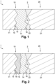
- FIG. 1 On the figure 1 is shown, partially and schematically, a mechanical system 1 according to the invention.
- the mechanical system 1 comprises two friction parts 10 and 20 separated by a lubricant 3 at their contact interface 2.
- this interface 2 is subjected to operating temperatures above 200°C. Under these conditions, the lubricant 3 is likely to be depleted.
- the parts 10 and 20 are moved by a relative movement in translation and/or in rotation.
- the parts 10 and 20 can have any shape and arrangement adapted to the intended application, in other words adapted to the type of mechanical system 1.
- the parts 10 and 20 are made of metal, preferably steel.
- Part 10 comprises a body 11, an outer surface 12, and an outer coating layer 14 deposited on surface 12.
- Layer 14 has an inner surface 15 and an outer surface 16.
- Surface 15 is secured to metal surface 12 during deposition of layer 14.
- Surface 16 faces part 20 at lubricated contact interface 2.
- Part 20 includes a body 21 and an outer surface 22. Part 20 has no outer coating layer. Surface 22 faces part 10 at lubricated contact interface 2.
- the surface 16 of the coating layer 14 and the surface 22 of the part 20 are in contact in places, at the lubricated contact interface 2 between the parts 10 and 20.
- the lubricant 3 forms a discontinuous film between surfaces 16 and 22, at interface 2.
- the lubricant 3 is chosen according to the intended application, in other words according to the type of mechanical system 1.
- the lubricant 3 can be a commercial automotive lubricant, such as an SAE 5W30 oil comprising conventional additives.
- the coating layer 14 is a compound of the tungsten carbide type doped with WC(N) nitrogen, with between 5 and 12 atomic % of nitrogen included.
- part 10 comprising coating layer 14 is suitable for operating in a lubricated medium at temperatures above 200°C.
- the doping of tungsten carbide layers with nitrogen leads to a reduction in friction in a lubricated medium, compared to conventional materials including undoped or lightly doped tungsten carbide WC (atomic % of nitrogen lower at 5 %).
- the part 10 comprises an underlayer 18 formed between the body 11 and the coating layer 14.
- the surface 12 is coated with the underlayer 18, then with the coating layer 14.
- the underlayer can be composed of chromium or chromium nitride. Chromium nitride can be deposited by reactive magnetron sputtering.
- part 20 includes an outer coating layer 24 deposited on surface 22.
- Layer 24 has an inner surface 25 and an outer surface 26.
- Surface 25 is secured to metal surface 22 when layer 24 is deposited.
- surface 26 faces the part 10 at the level of the lubricated contact interface 2.
- the lubricant 3 forms a discontinuous film between the surfaces 16 and 26 of the coating layers 14 and 24, at the lubricated contact interface 2 between the pieces 10 and 20.
- part 20 is also in accordance with the invention.
- the outer coating layer 24 has a WC(N) nitrogen-doped tungsten carbide type composition with between 5 and 12 atomic % nitrogen.
- the layers 14 and 24 preferably have a similar composition.
- part 20 may include an outer coating layer 24 having a different composition from layer 14.
- the part 20 may comprise an underlayer formed between the body 21 and the coating layer 24, as described above for the part 10 with reference to the figure 2 .
- This method consists in depositing a coating layer on steel specimens, then characterizing the different coatings, on the one hand, by friction in a lubricant and, on the other hand, by resistance to a temperature of 350°C.
- the coating materials tested are: chromium nitride CrN, tungsten carbide WC, tungsten carbides doped with nitrogen WC(N), DLC type a-C:H.
- the specimens Prior to the coating deposits, all the specimens undergo the same preparation steps.
- the specimens are degreased and positioned on a rotating sample holder driven by a planetary movement, according to the state of the art of vacuum deposition of hard thin layers.
- the vacuum chamber is pumped.
- the pumping is carried out at the same time as heating to 150° C. which makes it possible to activate the phenomena of desorption and to improve the quality of the vacuum.
- the pressure measured by a Penning gauge is less than 2 ⁇ 10 -5 mbar.
- the steel specimens are then ion etched in an argon plasma for one hour under a voltage of -150V applied to the specimens. At the end of pickling, the passivation oxide of the specimens has disappeared and the surfaces are suitable for receiving a deposit.
- the deposition of chromium nitride is carried out by reactive magnetron cathodic sputtering. During the end of the ion stripping of the specimen, the magnetron cathode is switched on at 5 kW behind a pre-spray cover to clean its surface for 5 minutes. At the end of the stripping, the ion assistance plasma is maintained, the bias voltage is lowered to -50V and the cover is opened so that a thin layer of chromium is deposited. During the deposition of this layer, the intensity emitted by the chromium atoms in the plasma is measured at a wavelength of 520 nm.
- This light intensity is normalized to 100 and a flow of nitrogen is introduced until the light emitted by the chromium decreases to a value of 50% of the intensity emitted in pure argon.
- a layer of CrN 2.7 ⁇ m thick and with a hardness of 1900 Hv under 10 mN is thus obtained.
- the deposition of tungsten carbide is carried out by sputtering a tungsten carbide target with 6% cobalt binder by mass.
- the target is cleaned under cache for 5 minutes at the end of the ion stripping.
- the ion assist plasma is turned off and the pre-spray cover is opened to begin WC deposition.
- a layer 2.1 ⁇ m thick and with a hardness of 1900 Hv under 10 mN is obtained.
- Nitrogen-doped tungsten carbide deposits are made by introducing a flow of reactive gas into the spray stream.
- the composition of the coating layer is stable and EDX analyzes indicate a composition comprising 40 at.% carbon, 12 at.% nitrogen, 8 at.% cobalt and 40 at.% tungsten. Under these conditions, the deposits doped with nitrogen have a hardness of 2900 Hv, markedly higher than that of a WC deposit without reactive gas.
- the deposition of DLC type aC:H is carried out by combining a PVD deposition technology to deposit a WC-based undercoat, which is gradually enriched in carbon to obtain a composition suitable for promoting the adhesion of the DLC layer developed in PACVD, as described in the document WO2012/156647 .
- the deposit thus obtained consists of a W-based layer 0.8 ⁇ m thick, on which a 2.2 ⁇ m layer of DLC has been deposited.
- the total deposit thickness is 3 ⁇ m and the surface hardness is 3200 Hv.
- THE figures 4 to 7 illustrate a first characterization test, consisting in carrying out a series of tribological tests on the specimens.
- FIG 4 is a schematic representation of a test bench 30, constituting a tribometer.
- the objective of the series of tests is to demonstrate the potential of particular coating materials to reduce friction in a lubricated environment, in comparison with a steel/steel contact. In order to only test the effects of the coatings, it is ensured that the tests are carried out under the same conditions. In particular, all the specimens have an identical initial roughness.
- the test bench 30 is used to characterize the friction within a mechanical system 40 consisting of two test specimens 41 and 42 made of steel, namely a cylinder 41 and a disc 42.
- the successive tests implement several systems 40, and therefore several specimens 41 and 42.
- the specimens 41 and 42 do not receive any coating, which makes it possible to characterize the steel/steel contact.
- the specimens 41 and 42 receive the same coating material.
- the test of two coated specimens 41 and 42 rubbing against each other corresponds to the configuration of the picture 3 ..
- the cylinders 41 used for the tests are cylindrical rollers made of 100Cr6 steel, coming from a roller bearing.
- the cylinders 41 have a diameter of 10 mm.
- the surface of cylinders 41 is polished over at least one generatrix until an arithmetic average roughness Ra ⁇ 0.02 ⁇ m is obtained, then this generatrix is coated with the material to be tested.
- the disks 42 used for the tests have a diameter of 25 mm and a thickness of 5 mm.
- a flat surface of each disk 42 is polished until an arithmetic average roughness Ra ⁇ 0.02 ⁇ m is obtained, then coated with the material to be tested.
- the disc 42 is installed in a tank 32 filled with a commercial automotive lubricant, in this case an oil 43 of the SAE 5W30 type comprising conventional additives.
- This oil 43 makes it possible to obtain a coefficient of friction of the order of 0.12-0.13 for a steel/steel contact in the limit lubrication regime.
- the disc 42 is fixed in the tank 32 by being immersed in the oil 43.
- the cylinder 41 is mounted on a support 31 suspended by flexible steel blades, which allow self-alignment of the cylinder 41 with the polished surface of the disc 42 when the specimens 41 and 42 are brought into contact.
- This self-alignment system is essential to the proper conduct of the tests, because it ensures that the geometry of the contact between the specimens 41 and 42 is perfectly controlled, so that it does not induce bias on the measurement of friction. .
- the alignment of specimens 41 and 42 in a cylinder-on-plane contact is the main difficulty of these tests.
- the support 31 of the cylinder 41 is connected to the rest of the tribometer by means of a piezoelectric sensor 33, placed facing the lubricated contact between the generatrix coated with the cylinder 41 and the flat surface coated with the disc 42.
- the sensor 33 makes it possible to measure the tangential force Ft, from which the coefficient of friction is determined.
- the lubricated contact interface between cylinder 41 and disk 42 measures 4 mm in length along the generatrix and 35 ⁇ m in contact width in the direction of friction.
- a contact pressure equal to 200 MPa is obtained.
- the contact pressure is an essential element in determining the coefficient of friction.
- the cylinder 41 wears faster than the disc 42, independently of the nature of the coating material.
- wear of the cylinder 41 after the test would induce a reduction in the contact pressure by enlargement of the contact area.
- the reduction in friction observed would therefore no longer be solely linked to the coating material, but also to the drop in contact pressure linked to wear.
- the disc 42 coated with 1200 grade SiC abrasive paper is lightly polished. This polishing eliminates the surface peaks, which induces a remarkable reduction in the wear rate of the cylinder 41 At the end of the test, the width of the friction mark is checked.
- the disc 42 is movable in translation following an alternating linear movement, thanks to a translation mechanism 34.
- the disc 42 is fixed in the tank 32, which is placed on a ball rail 35 and connected by a rod 36 to an eccentric element 37 movable in rotation.
- the eccentric element 37 is driven in rotation by a motor, not shown for the purpose of simplification.
- This mechanism 34 makes it possible to communicate to the tank 32 and therefore to the disk 42 an alternating linear movement over a stroke of 10 mm, following a sinusoidal law.
- Oil 43 is heated to 110° C. in tank 32, then mechanism 34 drives tank 32 back and forth.
- a preliminary test of 1 hour is carried out under a normal load Fn of 21 N, with a speed of rotation of the eccentric element 37 of 300 rotations per minute. This preliminary test is used to break in the surfaces and to stabilize the friction.
- FIG. 5 is a graph illustrating a measurement made with the piezoelectric sensor 33 fitted to the test bench 30, for a given coating material.
- the abscissa axis represents the time T in seconds.
- the left y-axis represents the tangential force Ft in newtons.
- the right axis of the ordinate represents the speed V of translation of the disk 42 in mm/s.
- curve Cfi is shown representing the evolution of the coefficient of friction Cf as a function of the instantaneous speed V of translation of the disc 42, from the measurements carried out for a given coating material.
- the abscissa axis represents the instantaneous speed V in mm/s obtained from the curve V42, while the ordinate axis represents the instantaneous coefficient of friction Cf determined from the curve Ft40.
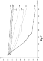
- FIG 7 is a graph illustrating the evolution of the coefficient of friction Cf for different coating materials. Each of the curves represented on this graph corresponds to the Cfi curve of the figure 6 , for a given coating material.
- the abscissa axis represents the instantaneous speed V in mm/s, while the ordinate axis represents the instantaneous coefficient of friction Cf.
- a first group of materials includes steel, CrN, undoped WC and lightly doped WC(N) (atomic % nitrogen less than 5%). These materials are characterized by a coefficient of friction Cf greater than 0.12, which decreases relatively little when the slip speed V increases. This level of friction is quite typical of the boundary lubrication regime and of the shearing of the anti-wear reaction films which grow on the surfaces (tribofilms), formed from the ZnDTP additives contained in the oil 43.
- the ZnDTP can decompose by reacting on a surface and form a tribofilm of Zn polyphosphates.
- a second group of materials comprises layers of nitrogen-doped WC whose nitrogen content reaches or exceeds 5 atomic %, corresponding to the references WC2, WC3, WC4 and the DLC of the a-C:H type. These materials are characterized by a friction coefficient Cf which decreases when the sliding speed V increases. This behavior is typical of the mixed lubrication regime. The reduction in friction in this regime is permitted by the fact that the friction surfaces remain smooth at the end of the test. The rate at which the coefficient of friction decreases reflects the roughness of the specimens after testing. Of all the materials tested here, DLC is the one that induces the greatest friction lowering. Observation of the friction surfaces after the test does not clearly show the presence of tribofilms. These films are either absent or much less thick than conventional tribofilms. A lesser thickness leads to limiting the roughness on the initially polished surfaces, since it is the island structure and the thickness which produce the roughness.
- a second characterization test of the coating materials is carried out using flat coated specimens.
- the test consists of heating the specimens to 350°C in air for 2 hours.
- the thickness of the coating layer is measured before heating, then after heating, to check that the material has remained intact.
- the choice of a temperature of 350°C makes it possible to accelerate the kinetics of oxidation and to classify the materials in a test duration of a few hours, instead of several tens of hours.
- Table 2 presents the thickness measurements of each of the coating layers before and after heating.
- the deposit thicknesses are characterized by means of the calotest. ⁇ u>Table 2 - coating thicknesses before and after heating ⁇ /u> Coating material
- Initial total thickness (in ⁇ m) Total thickness after 2 hours of heating at 350°C (in ⁇ m) CrN 2.7 2.7 WC (ref WC0) 2.1 2.1 Steel - - WC(N) (ref WC1) 2.2 2.1 WC(N) (ref WC2) 2.1 2.1 WC(N) (ref WC3) 2.3 2.3 WC(N) (ref WC4) 2.4 2.4 DLC type aC:H 3.0 0.8
- Table 3 presents the characteristics of the coatings determined using the various tests above. In particular, we present the evolution of the coefficient of friction between the sliding speeds of 50 mm/s and 300 mm/s, as well as the resistance of the coatings at a moderate temperature of 350°C.
- the CrN coatings, WC not doped with nitrogen (ref WC0), WC(N) lightly doped with nitrogen (ref WC1) are hard layers not in accordance with the invention. Friction in a lubricated medium does not lead to a reduction in friction compared to polished, uncoated steel. These materials are able to withstand a moderate temperature of 350°C.
- the DLC coating widely used in a lubricated medium, is not in accordance with the invention either.
- the reduction in friction in a lubricated medium is spectacular, but exposure to a temperature of 350° C. leads to the destruction of the coating by oxidation.
- references WC2, WC3 and WC4 are in accordance with the invention. Unlike undoped or lightly doped WC, a strong reduction in friction is observed in a lubricated medium. Although this reduction is not as spectacular as for DLC, these materials have the advantage of not undergoing degradation by exposure to a temperature of 350°C.
- the friction piece 10 can be adapted in terms of cost, functionality and performance.
Landscapes
- Chemical & Material Sciences (AREA)
- Engineering & Computer Science (AREA)
- General Engineering & Computer Science (AREA)
- Mechanical Engineering (AREA)
- Organic Chemistry (AREA)
- Chemical Kinetics & Catalysis (AREA)
- Materials Engineering (AREA)
- Metallurgy (AREA)
- General Chemical & Material Sciences (AREA)
- Oil, Petroleum & Natural Gas (AREA)
- Combustion & Propulsion (AREA)
- Other Surface Treatments For Metallic Materials (AREA)
- Physical Vapour Deposition (AREA)
- Lubricants (AREA)
- Pistons, Piston Rings, And Cylinders (AREA)
Claims (9)
- Reibungsteil (10) mit einer metallischen Oberfläche (12) und einer äußeren Beschichtungsschicht (14), gekennzeichnet dadurch, dass die äußere Beschichtungsschicht (14) aus stickstoffdotiertem Wolframkarbid WC(N) mit einem Stickstoffgehalt zwischen 5 und 12 Atom-% besteht,
die äußere Beschichtungsschicht (14) aus folgenden Bestandteilen besteht:• zwischen 40 und 43 Atom-% Kohlenstoff,• zwischen 40 und 43 Atom-% Wolfram,• zwischen 5 und 12 Atom-% Stickstoff,• zwischen 7 und 9 Atom-% Kobalt,• anderen Verbindungen, die insgesamt zwischen 0 und 8 Atom-% ausmachen. - Reibungsteil (10) nach Anspruch 1, gekennzeichnet dadurch, dass die metallische Oberfläche (12) ausschließlich mit der äußeren Beschichtungsschicht (14) beschichtet ist.
- Reibungsteil (10) nach Anspruch 1, gekennzeichnet dadurch, dass die metallische Oberfläche (12) mit zumindest einer Unterbeschichtung (18) beschichtet ist, die unterhalb der äußeren Beschichtungsschicht (14) gebildet wird.
- Reibungsteil nach Anspruch 3, gekennzeichnet dadurch, dass die Unterbeschichtung (18) aus Chrom oder Chromnitrid besteht.
- Mechanisches System (1) umfassend:• ein erstes Reibungsteil (10) gemäß einem der Ansprüche 1 bis 4,• ein zweites Reibungsteil (20), das in geschmiertem Kontakt mit dem ersten Reibungsteil (10) angeordnet ist;• ein Schmiermittel (3), das an einer geschmierten Kontaktstelle (2) zwischen den Reibungsteilen (10; 20) angebracht ist.
- Mechanisches System (1) nach Anspruch 5, gekennzeichnet dadurch, dass das zweite Reibungsteil (20) eine metallische Oberfläche (22) hat, die direkt in geschmiertem Kontakt mit dem ersten Reibungsteil (10) steht.
- Mechanisches System (1) nach Anspruch 5, gekennzeichnet dadurch, dass das zweite Reibungsteil (20) eine metallische Oberfläche (22) und eine äußere Beschichtungsschicht (24) auf der metallischen Oberfläche (22) aufweist, wobei die äußere Beschichtungsschicht (24) des zweiten Reibungsteils (20) aus stickstoffdotiertem Wolframkarbid WC(N) mit einem Stickstoffgehalt zwischen 5 und 12 Atom-% besteht und die äußere Beschichtungsschicht (24) aus folgenden Bestandteilen besteht:• zwischen 40 und 43 Atom-% Kohlenstoff,• zwischen 40 und 43 Atom-% Wolfram,• zwischen 5 und 12 Atom-% Stickstoff,• zwischen 7 und 9 Atom-% Kobalt,• anderen Verbindungen, die insgesamt zwischen 0 und 8 Atom-% ausmachen.
- Mechanisches System (1) nach Anspruch 7, gekennzeichnet dadurch, dass die äußere Beschichtungsschicht (14) des ersten Reibungsteils (10) und die äußere Beschichtungsschicht (24) des zweiten Reibungsteils (20) die gleiche Zusammensetzung haben.
- Verfahren zur Umsetzung eines Reibungsteils (10) gemäß einem der Ansprüche 1 bis 4, gekennzeichnet durch Schritte, die Folgendes umfassen:• Anordnen eines zweiten Reibungsteils (20) in geschmiertem Kontakt mit dem Reibungsteil (10);• Aufbringen eines Schmiermittels (3) an einer geschmierten Kontaktstelle (2) zwischen den Reibungsteilen (10; 20); und• Betreiben der Reibungsteile (10; 20), sodass die geschmierte Kontaktstelle (2) zwischen den Reibungsteilen (10; 20) eine Temperatur von über 200°C erreicht.
Applications Claiming Priority (2)
| Application Number | Priority Date | Filing Date | Title |
|---|---|---|---|
| FR1662033A FR3059757B1 (fr) | 2016-12-07 | 2016-12-07 | Piece de frottement, systeme mecanique comprenant une telle piece de frottement, et procede de mise en oeuvre |
| PCT/FR2017/053377 WO2018104641A1 (fr) | 2016-12-07 | 2017-12-04 | Piece de frottement, systeme mecanique comprenant une telle piece de frottement, et procede de mise en oeuvre |
Publications (3)
| Publication Number | Publication Date |
|---|---|
| EP3551923A1 EP3551923A1 (de) | 2019-10-16 |
| EP3551923B1 true EP3551923B1 (de) | 2023-07-19 |
| EP3551923C0 EP3551923C0 (de) | 2023-07-19 |
Family
ID=58314429
Family Applications (1)
| Application Number | Title | Priority Date | Filing Date |
|---|---|---|---|
| EP17817807.5A Active EP3551923B1 (de) | 2016-12-07 | 2017-12-04 | Reibungsteil, mechanisches system mit solch einem reibungsteil und verfahren zur implementierung |
Country Status (9)
| Country | Link |
|---|---|
| US (1) | US11236861B2 (de) |
| EP (1) | EP3551923B1 (de) |
| JP (1) | JP7179727B2 (de) |
| KR (1) | KR102255430B1 (de) |
| CN (1) | CN110062861B (de) |
| CA (1) | CA3045746C (de) |
| FR (1) | FR3059757B1 (de) |
| MX (1) | MX2019006544A (de) |
| WO (1) | WO2018104641A1 (de) |
Families Citing this family (1)
| Publication number | Priority date | Publication date | Assignee | Title |
|---|---|---|---|---|
| EP3650830B1 (de) * | 2018-11-08 | 2023-07-19 | Goodrich Actuation Systems SAS | Zweischeiben-tribometer der sich hin- und herbewegen und / oder sich nichtkollinear bewegen kann |
Family Cites Families (15)
| Publication number | Priority date | Publication date | Assignee | Title |
|---|---|---|---|---|
| FR2594143B1 (fr) * | 1986-02-07 | 1988-05-27 | Stephanois Rech Mec | Composite carbure de tungstene/cobalt a proprietes frottantes ameliorees |
| JP3221892B2 (ja) * | 1991-09-20 | 2001-10-22 | 帝国ピストンリング株式会社 | ピストンリング及びその製造法 |
| JP4495568B2 (ja) * | 2004-11-01 | 2010-07-07 | 株式会社神戸製鋼所 | 硬質皮膜 |
| JP4333794B2 (ja) * | 2007-11-06 | 2009-09-16 | トヨタ自動車株式会社 | 摺動構造 |
| JP2009155721A (ja) * | 2007-12-03 | 2009-07-16 | Kobe Steel Ltd | 摺動性に優れる硬質皮膜とその硬質皮膜の形成方法 |
| CN101497985A (zh) * | 2009-02-19 | 2009-08-05 | 吉林大学 | 一种单相六方碳化钨硬质涂层材料及其低温合成方法 |
| CN101856895B (zh) * | 2009-12-16 | 2012-07-11 | 中南大学 | 一种金刚石膜涂层钢铁基复合材料及其制备方法 |
| EP2412996A4 (de) * | 2010-05-10 | 2012-09-26 | Across Co | Reibungskupplung |
| DE102011100974A1 (de) * | 2011-05-09 | 2012-11-15 | Knorr-Bremse Systeme für Schienenfahrzeuge GmbH | Schienenrad und Verfahren zur Herstellung eines Schienenrades |
| FR2975404B1 (fr) | 2011-05-19 | 2014-01-24 | Hydromecanique & Frottement | Piece avec revetement dlc et procede d'application du revetement dlc |
| CN102560487A (zh) * | 2012-01-19 | 2012-07-11 | 浙江汇锦梯尔镀层科技有限公司 | 一种铸铁件及其表面复合处理方法 |
| BR102012003607A2 (pt) * | 2012-02-16 | 2013-10-29 | Mahle Metal Leve Sa | Componente deslizante para uso em motores de combustão interna |
| JP6267604B2 (ja) * | 2014-03-03 | 2018-01-24 | 株式会社神戸製鋼所 | 硬質皮膜およびその形成方法、ならびに鋼板熱間成型用金型 |
| CN104264095A (zh) * | 2014-09-11 | 2015-01-07 | 芜湖鼎瀚再制造技术有限公司 | 一种CBN-WC-10Co纳米涂层 |
| CN105156503B (zh) * | 2015-10-09 | 2017-11-07 | 龙口中宇热管理系统科技有限公司 | 一种两级多片式电磁离合器 |
-
2016
- 2016-12-07 FR FR1662033A patent/FR3059757B1/fr active Active
-
2017
- 2017-12-04 CA CA3045746A patent/CA3045746C/fr active Active
- 2017-12-04 JP JP2019530408A patent/JP7179727B2/ja active Active
- 2017-12-04 EP EP17817807.5A patent/EP3551923B1/de active Active
- 2017-12-04 MX MX2019006544A patent/MX2019006544A/es unknown
- 2017-12-04 US US16/467,636 patent/US11236861B2/en active Active
- 2017-12-04 CN CN201780076391.7A patent/CN110062861B/zh active Active
- 2017-12-04 WO PCT/FR2017/053377 patent/WO2018104641A1/fr not_active Ceased
- 2017-12-04 KR KR1020197019471A patent/KR102255430B1/ko active Active
Also Published As
| Publication number | Publication date |
|---|---|
| KR20190094394A (ko) | 2019-08-13 |
| CA3045746C (fr) | 2023-03-07 |
| US20200080686A1 (en) | 2020-03-12 |
| US11236861B2 (en) | 2022-02-01 |
| FR3059757B1 (fr) | 2018-11-16 |
| CN110062861A (zh) | 2019-07-26 |
| FR3059757A1 (fr) | 2018-06-08 |
| JP7179727B2 (ja) | 2022-11-29 |
| WO2018104641A1 (fr) | 2018-06-14 |
| CN110062861B (zh) | 2022-05-13 |
| EP3551923C0 (de) | 2023-07-19 |
| BR112019011575A2 (pt) | 2019-10-22 |
| JP2020507003A (ja) | 2020-03-05 |
| CA3045746A1 (fr) | 2018-06-14 |
| EP3551923A1 (de) | 2019-10-16 |
| KR102255430B1 (ko) | 2021-05-24 |
| MX2019006544A (es) | 2019-08-01 |
Similar Documents
| Publication | Publication Date | Title |
|---|---|---|
| WO2013042765A1 (ja) | 硬質膜、硬質膜形成体、および転がり軸受 | |
| JP6718452B2 (ja) | ピストンリング及びその製造方法 | |
| JP6422495B2 (ja) | ピストンリング | |
| EP3551923B1 (de) | Reibungsteil, mechanisches system mit solch einem reibungsteil und verfahren zur implementierung | |
| JP5993680B2 (ja) | 転がり軸受およびその製造方法 | |
| JP2022109260A (ja) | ピストンリング及びその製造方法 | |
| JP2018076958A (ja) | ピストンリング | |
| CA2871978C (fr) | Chemise de moteur a combustion interne | |
| WO2019107442A1 (ja) | 摺動部材 | |
| JP6499949B2 (ja) | ピストンリング | |
| JP2019116677A (ja) | 摺動部材 | |
| EP1875092B1 (de) | Führungselementpaar, von dem eines aus einem speziellen stahl hergestellt ist, was zu weniger festfressen führt | |
| WO2021130460A1 (fr) | Procédé de traitement d'une pièce en métal ferreux et pièce en métal ferreux | |
| JP5379734B2 (ja) | 転がり軸受 | |
| JP6416066B2 (ja) | ピストンリング | |
| JP7159111B2 (ja) | 摺動部材と潤滑油との組み合わせ | |
| Bhowmick et al. | Enhanced high-temperature tribological performance of fluorinated tetrahedral amorphous carbon (ta-C: F) coatings in sliding applications | |
| FR3165278A1 (fr) | Procédé de revêtement d’un substrat par pulvérisation cathodique magnétron réactive et pièce comportant un tel substrat revêtu. | |
| FR3097562A1 (fr) | Procédé de fabrication d’une pièce abradable de turbomachine et pièce abradable | |
| JP2007010051A (ja) | 高速摺動機構及びその製造方法 |
Legal Events
| Date | Code | Title | Description |
|---|---|---|---|
| STAA | Information on the status of an ep patent application or granted ep patent |
Free format text: STATUS: UNKNOWN |
|
| STAA | Information on the status of an ep patent application or granted ep patent |
Free format text: STATUS: THE INTERNATIONAL PUBLICATION HAS BEEN MADE |
|
| PUAI | Public reference made under article 153(3) epc to a published international application that has entered the european phase |
Free format text: ORIGINAL CODE: 0009012 |
|
| STAA | Information on the status of an ep patent application or granted ep patent |
Free format text: STATUS: REQUEST FOR EXAMINATION WAS MADE |
|
| 17P | Request for examination filed |
Effective date: 20190528 |
|
| AK | Designated contracting states |
Kind code of ref document: A1 Designated state(s): AL AT BE BG CH CY CZ DE DK EE ES FI FR GB GR HR HU IE IS IT LI LT LU LV MC MK MT NL NO PL PT RO RS SE SI SK SM TR |
|
| AX | Request for extension of the european patent |
Extension state: BA ME |
|
| STAA | Information on the status of an ep patent application or granted ep patent |
Free format text: STATUS: EXAMINATION IS IN PROGRESS |
|
| DAV | Request for validation of the european patent (deleted) | ||
| DAX | Request for extension of the european patent (deleted) | ||
| 17Q | First examination report despatched |
Effective date: 20200312 |
|
| RAP3 | Party data changed (applicant data changed or rights of an application transferred) |
Owner name: HYDROMECANIQUE ET FROTTEMENT |
|
| REG | Reference to a national code |
Ref country code: DE Ref legal event code: R079 Free format text: PREVIOUS MAIN CLASS: F16N0001000000 Ipc: C23C0014000000 Ref country code: DE Ref legal event code: R079 Ref document number: 602017071554 Country of ref document: DE Free format text: PREVIOUS MAIN CLASS: F16N0001000000 Ipc: C23C0014000000 |
|
| GRAP | Despatch of communication of intention to grant a patent |
Free format text: ORIGINAL CODE: EPIDOSNIGR1 |
|
| STAA | Information on the status of an ep patent application or granted ep patent |
Free format text: STATUS: GRANT OF PATENT IS INTENDED |
|
| RIC1 | Information provided on ipc code assigned before grant |
Ipc: C23C 14/06 20060101ALI20230404BHEP Ipc: C23C 14/00 20060101AFI20230404BHEP |
|
| INTG | Intention to grant announced |
Effective date: 20230425 |
|
| GRAS | Grant fee paid |
Free format text: ORIGINAL CODE: EPIDOSNIGR3 |
|
| GRAA | (expected) grant |
Free format text: ORIGINAL CODE: 0009210 |
|
| STAA | Information on the status of an ep patent application or granted ep patent |
Free format text: STATUS: THE PATENT HAS BEEN GRANTED |
|
| P01 | Opt-out of the competence of the unified patent court (upc) registered |
Effective date: 20230527 |
|
| AK | Designated contracting states |
Kind code of ref document: B1 Designated state(s): AL AT BE BG CH CY CZ DE DK EE ES FI FR GB GR HR HU IE IS IT LI LT LU LV MC MK MT NL NO PL PT RO RS SE SI SK SM TR |
|
| REG | Reference to a national code |
Ref country code: GB Ref legal event code: FG4D Free format text: NOT ENGLISH |
|
| REG | Reference to a national code |
Ref country code: CH Ref legal event code: EP |
|
| REG | Reference to a national code |
Ref country code: DE Ref legal event code: R096 Ref document number: 602017071554 Country of ref document: DE |
|
| REG | Reference to a national code |
Ref country code: IE Ref legal event code: FG4D Free format text: LANGUAGE OF EP DOCUMENT: FRENCH |
|
| U01 | Request for unitary effect filed |
Effective date: 20230801 |
|
| U07 | Unitary effect registered |
Designated state(s): AT BE BG DE DK EE FI FR IT LT LU LV MT NL PT SE SI Effective date: 20230807 |
|
| P04 | Withdrawal of opt-out of the competence of the unified patent court (upc) registered |
Effective date: 20230802 |
|
| REG | Reference to a national code |
Ref country code: LT Ref legal event code: MG9D |
|
| PG25 | Lapsed in a contracting state [announced via postgrant information from national office to epo] |
Ref country code: GR Free format text: LAPSE BECAUSE OF FAILURE TO SUBMIT A TRANSLATION OF THE DESCRIPTION OR TO PAY THE FEE WITHIN THE PRESCRIBED TIME-LIMIT Effective date: 20231020 |
|
| PG25 | Lapsed in a contracting state [announced via postgrant information from national office to epo] |
Ref country code: IS Free format text: LAPSE BECAUSE OF FAILURE TO SUBMIT A TRANSLATION OF THE DESCRIPTION OR TO PAY THE FEE WITHIN THE PRESCRIBED TIME-LIMIT Effective date: 20231119 |
|
| PG25 | Lapsed in a contracting state [announced via postgrant information from national office to epo] |
Ref country code: RS Free format text: LAPSE BECAUSE OF FAILURE TO SUBMIT A TRANSLATION OF THE DESCRIPTION OR TO PAY THE FEE WITHIN THE PRESCRIBED TIME-LIMIT Effective date: 20230719 Ref country code: NO Free format text: LAPSE BECAUSE OF FAILURE TO SUBMIT A TRANSLATION OF THE DESCRIPTION OR TO PAY THE FEE WITHIN THE PRESCRIBED TIME-LIMIT Effective date: 20231019 Ref country code: IS Free format text: LAPSE BECAUSE OF FAILURE TO SUBMIT A TRANSLATION OF THE DESCRIPTION OR TO PAY THE FEE WITHIN THE PRESCRIBED TIME-LIMIT Effective date: 20231119 Ref country code: HR Free format text: LAPSE BECAUSE OF FAILURE TO SUBMIT A TRANSLATION OF THE DESCRIPTION OR TO PAY THE FEE WITHIN THE PRESCRIBED TIME-LIMIT Effective date: 20230719 Ref country code: GR Free format text: LAPSE BECAUSE OF FAILURE TO SUBMIT A TRANSLATION OF THE DESCRIPTION OR TO PAY THE FEE WITHIN THE PRESCRIBED TIME-LIMIT Effective date: 20231020 |
|
| U20 | Renewal fee for the european patent with unitary effect paid |
Year of fee payment: 7 Effective date: 20231226 |
|
| PG25 | Lapsed in a contracting state [announced via postgrant information from national office to epo] |
Ref country code: PL Free format text: LAPSE BECAUSE OF FAILURE TO SUBMIT A TRANSLATION OF THE DESCRIPTION OR TO PAY THE FEE WITHIN THE PRESCRIBED TIME-LIMIT Effective date: 20230719 |
|
| REG | Reference to a national code |
Ref country code: DE Ref legal event code: R097 Ref document number: 602017071554 Country of ref document: DE |
|
| PG25 | Lapsed in a contracting state [announced via postgrant information from national office to epo] |
Ref country code: ES Free format text: LAPSE BECAUSE OF FAILURE TO SUBMIT A TRANSLATION OF THE DESCRIPTION OR TO PAY THE FEE WITHIN THE PRESCRIBED TIME-LIMIT Effective date: 20230719 |
|
| PG25 | Lapsed in a contracting state [announced via postgrant information from national office to epo] |
Ref country code: SM Free format text: LAPSE BECAUSE OF FAILURE TO SUBMIT A TRANSLATION OF THE DESCRIPTION OR TO PAY THE FEE WITHIN THE PRESCRIBED TIME-LIMIT Effective date: 20230719 Ref country code: RO Free format text: LAPSE BECAUSE OF FAILURE TO SUBMIT A TRANSLATION OF THE DESCRIPTION OR TO PAY THE FEE WITHIN THE PRESCRIBED TIME-LIMIT Effective date: 20230719 Ref country code: ES Free format text: LAPSE BECAUSE OF FAILURE TO SUBMIT A TRANSLATION OF THE DESCRIPTION OR TO PAY THE FEE WITHIN THE PRESCRIBED TIME-LIMIT Effective date: 20230719 Ref country code: CZ Free format text: LAPSE BECAUSE OF FAILURE TO SUBMIT A TRANSLATION OF THE DESCRIPTION OR TO PAY THE FEE WITHIN THE PRESCRIBED TIME-LIMIT Effective date: 20230719 Ref country code: SK Free format text: LAPSE BECAUSE OF FAILURE TO SUBMIT A TRANSLATION OF THE DESCRIPTION OR TO PAY THE FEE WITHIN THE PRESCRIBED TIME-LIMIT Effective date: 20230719 |
|
| PLBE | No opposition filed within time limit |
Free format text: ORIGINAL CODE: 0009261 |
|
| STAA | Information on the status of an ep patent application or granted ep patent |
Free format text: STATUS: NO OPPOSITION FILED WITHIN TIME LIMIT |
|
| 26N | No opposition filed |
Effective date: 20240422 |
|
| REG | Reference to a national code |
Ref country code: CH Ref legal event code: PL |
|
| PG25 | Lapsed in a contracting state [announced via postgrant information from national office to epo] |
Ref country code: MC Free format text: LAPSE BECAUSE OF FAILURE TO SUBMIT A TRANSLATION OF THE DESCRIPTION OR TO PAY THE FEE WITHIN THE PRESCRIBED TIME-LIMIT Effective date: 20230719 |
|
| GBPC | Gb: european patent ceased through non-payment of renewal fee |
Effective date: 20231204 |
|
| PG25 | Lapsed in a contracting state [announced via postgrant information from national office to epo] |
Ref country code: MC Free format text: LAPSE BECAUSE OF FAILURE TO SUBMIT A TRANSLATION OF THE DESCRIPTION OR TO PAY THE FEE WITHIN THE PRESCRIBED TIME-LIMIT Effective date: 20230719 |
|
| REG | Reference to a national code |
Ref country code: IE Ref legal event code: MM4A |
|
| PG25 | Lapsed in a contracting state [announced via postgrant information from national office to epo] |
Ref country code: IE Free format text: LAPSE BECAUSE OF NON-PAYMENT OF DUE FEES Effective date: 20231204 |
|
| PG25 | Lapsed in a contracting state [announced via postgrant information from national office to epo] |
Ref country code: GB Free format text: LAPSE BECAUSE OF NON-PAYMENT OF DUE FEES Effective date: 20231204 |
|
| PG25 | Lapsed in a contracting state [announced via postgrant information from national office to epo] |
Ref country code: CH Free format text: LAPSE BECAUSE OF NON-PAYMENT OF DUE FEES Effective date: 20231231 |
|
| PG25 | Lapsed in a contracting state [announced via postgrant information from national office to epo] |
Ref country code: IE Free format text: LAPSE BECAUSE OF NON-PAYMENT OF DUE FEES Effective date: 20231204 Ref country code: GB Free format text: LAPSE BECAUSE OF NON-PAYMENT OF DUE FEES Effective date: 20231204 Ref country code: CH Free format text: LAPSE BECAUSE OF NON-PAYMENT OF DUE FEES Effective date: 20231231 |
|
| P05 | Withdrawal of opt-out of the competence of the unified patent court (upc) changed |
Free format text: CASE NUMBER: APP_558629/2023 Effective date: 20230807 |
|
| U20 | Renewal fee for the european patent with unitary effect paid |
Year of fee payment: 8 Effective date: 20241227 |
|
| PG25 | Lapsed in a contracting state [announced via postgrant information from national office to epo] |
Ref country code: CY Free format text: LAPSE BECAUSE OF FAILURE TO SUBMIT A TRANSLATION OF THE DESCRIPTION OR TO PAY THE FEE WITHIN THE PRESCRIBED TIME-LIMIT; INVALID AB INITIO Effective date: 20171204 |
|
| PG25 | Lapsed in a contracting state [announced via postgrant information from national office to epo] |
Ref country code: HU Free format text: LAPSE BECAUSE OF FAILURE TO SUBMIT A TRANSLATION OF THE DESCRIPTION OR TO PAY THE FEE WITHIN THE PRESCRIBED TIME-LIMIT; INVALID AB INITIO Effective date: 20171204 |
|
| PG25 | Lapsed in a contracting state [announced via postgrant information from national office to epo] |
Ref country code: TR Free format text: LAPSE BECAUSE OF FAILURE TO SUBMIT A TRANSLATION OF THE DESCRIPTION OR TO PAY THE FEE WITHIN THE PRESCRIBED TIME-LIMIT Effective date: 20230719 |
|
| U20 | Renewal fee for the european patent with unitary effect paid |
Year of fee payment: 9 Effective date: 20251226 |