EP3551957B1 - Échangeur de chaleur et procédé d'utilisation de celui-ci - Google Patents
Échangeur de chaleur et procédé d'utilisation de celui-ci Download PDFInfo
- Publication number
- EP3551957B1 EP3551957B1 EP17811925.1A EP17811925A EP3551957B1 EP 3551957 B1 EP3551957 B1 EP 3551957B1 EP 17811925 A EP17811925 A EP 17811925A EP 3551957 B1 EP3551957 B1 EP 3551957B1
- Authority
- EP
- European Patent Office
- Prior art keywords
- heat
- conducting
- heat exchanger
- conducting structure
- grids
- Prior art date
- Legal status (The legal status is an assumption and is not a legal conclusion. Google has not performed a legal analysis and makes no representation as to the accuracy of the status listed.)
- Active
Links
Images


Classifications
-
- F—MECHANICAL ENGINEERING; LIGHTING; HEATING; WEAPONS; BLASTING
- F28—HEAT EXCHANGE IN GENERAL
- F28F—DETAILS OF HEAT-EXCHANGE AND HEAT-TRANSFER APPARATUS, OF GENERAL APPLICATION
- F28F1/00—Tubular elements; Assemblies of tubular elements
- F28F1/10—Tubular elements and assemblies thereof with means for increasing heat-transfer area, e.g. with fins, with projections, with recesses
- F28F1/12—Tubular elements and assemblies thereof with means for increasing heat-transfer area, e.g. with fins, with projections, with recesses the means being only outside the tubular element
- F28F1/122—Tubular elements and assemblies thereof with means for increasing heat-transfer area, e.g. with fins, with projections, with recesses the means being only outside the tubular element and being formed of wires
-
- F—MECHANICAL ENGINEERING; LIGHTING; HEATING; WEAPONS; BLASTING
- F28—HEAT EXCHANGE IN GENERAL
- F28F—DETAILS OF HEAT-EXCHANGE AND HEAT-TRANSFER APPARATUS, OF GENERAL APPLICATION
- F28F2255/00—Heat exchanger elements made of materials having special features or resulting from particular manufacturing processes
- F28F2255/12—Heat exchanger elements made of materials having special features or resulting from particular manufacturing processes expanded or perforated metal plate
Definitions
- the invention relates to a heat exchanger with at least one heat transfer surface, which is connected to at least one heat-conducting structure.
- the invention further relates to a method for evaporating a liquid, in which heat is supplied to a liquid.
- the invention relates to a method for heat transfer between a first heat transfer medium and a second heat transfer medium by means of a heat exchanger.
- Devices and methods of the type mentioned at the beginning can be used in a variety of ways, for example for cooling heat from process systems or machines or as a component of heat pumps and air conditioning devices; such heat exchangers are, for example, used EP 0 693 666 A2 known.
- EP 0 693 666 A2 describes the preamble of claim 1.
- Fin heat exchangers are known from practice. These contain a lamella package, with individual lamellas made from a sheet of metal or an alloy.
- the plate pack can contain aluminum or copper, for example. There are holes in the plate pack through which pipes are routed.
- a first heat transfer medium for example water or thermal oil, flows through the pipes.
- a second heat transfer medium for example ambient air, flows through the plate pack. Heat can be transferred either from the first heat transfer medium to the second heat transfer medium or vice versa.
- the fin package is thermally connected to the pipes and means that the surface area available for heat exchange is increased.
- the invention is therefore based on the object of providing a heat exchanger with improved performance.
- a heat exchanger with at least one heat transfer surface is proposed.
- Heat can be added to or removed from the heat transfer surface, for example through electrical heating resistors, Peltier elements or waste heat utilization.
- the heat transfer surface may be a pipe wall or include a portion of a pipe wall that delimits an interior space of a pipe from the exterior space surrounding the pipe.
- a heat transfer medium can circulate in the pipe, to which sensible and/or latent heat is supplied or from which sensible and/or latent heat is removed.
- the heat transfer surface may be part of a container wall, the container containing a latent heat storage.
- the cross section of the pipe can be polygonal or round.
- the cross-sectional area can have the same width as height, so that the pipe cross-section is square or is circular.
- the width of the tube may be greater than its height, so that the cross section is rectangular or elliptical.
- a heat exchanger that has a plurality of such tubes can also be referred to as a plate heat exchanger.
- the heat transfer surface may include or consist of a metal or alloy. In some embodiments of the invention, the heat transfer surface may contain or consist of aluminum and/or copper and/or stainless steel.
- the heat transfer surface with a heat-conducting structure at least on one side.
- the heat-conducting structure is thermally coupled to the heat transfer surface, so that the area available for heat exchange is increased compared to the pure heat transfer surface.
- the heat-conducting structure contains at least two heat-conducting grids, which are cohesively connected to one another.
- the heat-conducting grids can be soldered or welded or sintered together.
- the heat-conducting grids allow efficient flow of a heat transfer medium due to the openings in the grid.
- the heat-conducting grids have internal surfaces, which contribute to increasing the total surface area available for heat exchange. Due to the cohesive connection of adjacent heat-conducting grids within the heat-conducting structure, the distance between the heat-conducting grids is reduced compared to known plate packs.
- the number of heat-conducting grids can be increased, which increases the surface area available for heat exchange.
- the cohesive connection between adjacent heat conduction grids increases the mechanical stability, so that the heat conduction grids can have a smaller material thickness than usual fins of a finned heat exchanger. Since there is nevertheless a continuous material structure within the plane defined by a heat-conducting grid, the heat can be supplied or removed with great efficiency from the heat transfer surface of the at least one tube of the heat exchanger via the heat-conducting grid or supplied to the heat transfer medium flowing in the tube.
- At least one heat-conducting grid can be selected from a perforated material layer and/or an expanded metal grid and/or a braid.
- the perforated material layer can, for example, be or contain a sheet or metal foil made of a metal or an alloy.
- the material layer can be flat or curved or corrugated in order to create gaps between adjacent heat-conducting grids of the heat-conducting structure.
- An expanded metal grid or a braid or a knitted fabric can have anisotropic thermal conductivity in the two spatial directions of the plane defined by the sheet structure of the expanded metal grid, so that the thermal conductivity can be greater orthogonally to the heat transfer surface than in a direction parallel to the heat transfer surface.
- the meshes formed in the grid are not square, but have a greater extent in a spatial direction than in a spatial direction orthogonal thereto.
- the number or surface density of the threads present in the braid or fabric can be greater in one spatial direction than in a spatial direction orthogonal thereto.
- the individual thermal grids may have a material thickness of less than about 200 ⁇ m or less than about 150 ⁇ m or less than about 60 ⁇ m. In some embodiments of the invention, the individual heat conducting grids may have a material thickness of more than about 20 ⁇ m or more than about 30 ⁇ m or more than about 90 ⁇ m. In some embodiments of the invention, the heat-conducting grids can have a material thickness of approximately 50 ⁇ m. The material thicknesses mentioned allow, on the one hand, sufficient heat transport within the plane defined by the heat-conducting grid and, on the other hand, sufficient packing density in order to achieve high power densities of the heat exchanger according to the invention.
- the heat-conducting structure can be arranged on the heat transfer surface in such a way that the heat-conducting grid forms an angle of approximately 50° to approximately 130° or of approximately 70° to approximately 110° or of approximately 80° with the tube or the longitudinal axis of the tube ° to include about 100° or about 90°.
- this allows efficient flow through the heat-conducting structure, for example in a cross-flow heat exchanger.
- the projected area of the heat-conducting structure is maximum when it is arranged at approximately 90° to the heat transfer surface and to the flow of the heat transfer medium. This allows flow losses to be minimized and heat transfer performance to be maximized.
- the heat-conducting structure can be produced by sintering the heat-conducting grids.
- a stack of heat-conducting grids can be heated to a predetermined temperature in a protective gas atmosphere or vacuum.
- this temperature can be selected to be below the melting temperature and above half the melting temperature of the material used for the heat-conducting grids. This is how it comes It is used to weld the heat-conducting grids or to form sintered necks at individual contact points. This can increase the mechanical stability of even thin heat-conducting grids to such an extent that the heat exchanger can be designed to be mechanically robust.
- heat-conducting structure whose porosity is only slightly lower than the open area of individual heat-conducting grids.
- the heat-conducting structure according to the invention can therefore be flowed through by the heat transfer medium with low pressure losses and, when used as an evaporator, a large-area three-phase boundary can be formed in the heat-conducting structure between the heat-transferring surface of the heat-conducting structure, the liquid to be evaporated and the vapor.
- the heat conducting structure may have a height of about 1 mm to about 10 mm, or about 1 mm to about 5 mm, or about 1 mm to about 3 mm.
- Heat-conducting structures which have the specified height dimensions starting from the surface of the heat transfer surface are particularly suitable for evaporating a liquid from a liquid sump.
- the heat-conducting structure can be partially or completely immersed in the liquid sump.
- the heat conducting structure may have a height of from about 15 mm to about 40 mm or from about 20 mm to about 30 mm. The height extends vertically from the surface of the pipe wall to the highest point of the heat-conducting structure.
- Such heat-conducting structures can have a gaseous heat transfer medium flowing through them and can be used as a heat exchanger between two heat transfer media and can also transmit large amounts of power due to the large area available.
- the heat conduction structure may include or consist of between about 50 and about 2,500, or between about 100 and about 1,000, or between about 150 and about 500, or between about 200 and about 300 heat conduction grids.
- the heat-conducting grids can be placed on top of each other and connected to one another by sintering, gluing or soldering. Sintering in particular allows a simple manufacturing process for the heat-conducting structure according to the invention. After sintering, the heat-conducting structure has a comparatively high mechanical stability and at the same time a high porosity, which allows an efficient flow of a particularly gaseous heat transfer medium.
- the heat-conducting structure can efficiently conduct heat in the individual levels of the heat-conducting grids, whereas there is reduced thermal conductivity in the direction of the normal vector of the heat-conducting grids due to the only point-like connection of the individual heat-conducting grids to one another.
- the heat-conducting structure which is composed of a large number of heat-conducting grids, can subsequently be cut to the desired size and joined to the heat transfer surface of a heat exchanger in a form-fitting or material-fitting manner.
- a plurality of heat-conducting structures can also be attached to a heat transfer surface.
- the normal vector of the heat conduction grid may form an angle between about 30° and about 150°, or between about 45° and about 135°, or between about 70° and about 110°, or about 90° to the normal vector of the heat transfer surface.
- the heat is dissipated from the heat transfer surface along the planes of the heat conduction grids.
- the heat-conducting structure has a porosity of about 70% to about 90% or about 80% to about 85%. According to the invention, it was recognized that even when a large number of heat-conducting grids are placed one on top of the other, the open area, which significantly determines the flow resistance of a heat transfer medium, only decreases to a small extent.
- the mesh size of the individual meshes of a thermal grid can be between about 1.5 mm and about 3.5 mm.
- the width of a stitch may be greater than its height.
- the width of a mesh may be between about 2.2 mm to about 3.5 mm.
- the height of a mesh may be between about 1.5 mm and about 2.5 mm.
- the web width of the thermal grid i.e. the material thickness remaining between adjacent meshes, can be between about 180 ⁇ m and about 50 ⁇ m or between about 150 ⁇ m and about 80 ⁇ m.
- the web width can be between about 120 ⁇ m and about 90 ⁇ m.
- the comparatively large mesh size thus allows the efficient flow of a heat transfer medium or, in the case of an evaporator, the efficient removal of a gaseous medium, whereas the remaining web width still ensures sufficient heat transport within the heat-conducting structure.
- the thermal conductivity of the heat-conducting structure in the direction of the normal vector of the plane defined by the heat-conducting grids can be lower by more than a factor of 7 or more than a factor of 8 or more than a factor of 10 than in a direction orthogonal to the normal vector.
- This behavior results from the fact that within the plane defined by the individual heat conduction grids due to the connected Material layer of the heat-conducting grid has a comparatively large cross-sectional area available for heat transport.
- adjacent heat conduction grids are only connected to one another at points by sintered necks, solder joints or adhesive connections, so that the heat conduction in the direction of the normal vector is reduced.
- the heat exchanger can further contain a sorbent which is arranged on and/or in the heat-conducting structure.
- the sorbent can be applied, for example, by plasma coating, dip coating or spray coating. This allows the heat exchanger according to the invention to be used as a sorber in a thermal compressor of a sorption heat pump. In other embodiments of the invention, the heat exchanger can also be used as a condenser and/or evaporator of a heat pump.
- the heat conducting structure may be pleated.
- the heat-conducting structure can be connected to the tube in a materially bonded manner, for example by soldering.
- soldering for example, a solder paste can be used, which is applied to the joint and subsequently heated.
- this relates to a method for evaporating a liquid, in which the heat-conducting structure of a heat exchanger is at least partially immersed in a sump and a heat transfer medium with an elevated temperature is supplied via at least one pipe of the heat exchanger.
- a heat energy source is used via the heat conduction structure of the heat exchanger Transferring heat to a liquid, causing the liquid to evaporate.
- the liquid may be supplied via a sump.
- the heat exchanger can be completely or partially immersed in the sump.
- the liquid can also be supplied to the heat exchanger by sprinkling.
- the liquid to be evaporated can also condense beforehand on the heat exchanger and be temporarily stored there.
- nucleate boiling can be created in the liquid.
- Bubble boiling is the formation of gas phases through heating within the liquid.
- the heat exchanger according to the invention Due to the meshes within the heat-conducting grids, which are each delimited by webs with edges, the heat exchanger according to the invention also has many nucleation points for bubble formation and thus an improved evaporation performance during nucleate boiling compared to known finned heat exchangers.
- the contact areas between individual heat-conducting grids that arise during the heat treatment of the heat-conducting structure also form additional nucleation points for the formation of bubbles.
- the heat-conducting grids used according to the invention with low material thickness can be used to put together many heat-conducting grids in a limited space.
- the small meshes formed within these heat-conducting grids lead to many edges and corners and thus to a large number of nucleation points for bubble formation.
- the evaporation performance of a heat exchanger according to the invention can therefore be significantly increased compared to known heat exchangers.
- this relates to a method for transferring heat between a first heat transfer medium to a second heat transfer medium by means of a heat exchanger.
- a heat transfer medium flows inside a pipe and is separated by the pipe wall from the outside space in which the other heat transfer medium flows.
- the area available for heat transfer can be increased by heat-conducting structures, which are arranged on one or both sides of the pipe wall.
- the outside of the pipe wall in particular can be provided with heat-conducting structures.
- the first heat transfer medium can be a liquid, for example heating water, cooling water or thermal oil.
- the second heat transfer medium can be gaseous, for example ambient air or an exhaust gas stream.
- the gaseous second heat transfer medium flows through the heat-conducting structure according to the invention. Since the porosity, ie the volume of the pores resulting from the meshes, is comparatively large in relation to the total volume of the heat-conducting structure, the heat-conducting structure consisting of a large number of heat-conducting grids can also be flowed through by a gaseous medium, so that efficient heat exchange can take place.
- FIG. 1 shows an embodiment of a heat conduction grid according to the present invention.
- the heat conduction grid according to Figure 1 consists of an expanded metal, which is available by making slots in a metal foil or sheet and then pulling it apart. This creates meshes 25, which are separated from each other by webs 23.
- the metal foil or sheet can contain or consist of copper or aluminum.
- the meshes 25 may have a greater width a and a lesser height b.
- the width a can be between about 2.5 and about 3 mm, whereas the height b is between about 1.5 mm and about 2.5 mm.
- the webs 23 can be between about 90 ⁇ m and about 100 ⁇ m wide.
- the material thickness of the expanded metal grid can be between approximately 40 ⁇ m and approximately 60 ⁇ m.
- the heat conduction grid 20 Due to the production method of the heat conduction grid 20 as an expanded metal grid, a continuous metallic structure results within the plane defined by the expanded metal grid 20, so that heat can be efficiently conducted within the plane defined by the expanded metal. If the meshes 25 of the heat transfer grid 20 are flowed through by a gaseous heat transfer medium, for example, this heat can also be given off to the heat transfer medium or absorbed from the heat transfer medium with good efficiency.
- a heat-conducting grid 20 can also be produced by perforating a metal foil or by braiding wires.
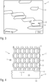
- Figure 2 shows a heat-conducting structure 2, which is composed of a large number of heat-conducting grids 20. For this purpose, around 50 to around 400 of the in Figure 1 The heat conduction grid shown is cut to size and placed on top of each other.
- the heat-conducting grids can be joined, for example, by soldering.
- a soldering paste which contains solder and flux, can be applied to the thermal conduction grid 20 in a point-like or flat manner.
- at least one thermal conduction grid can be oxidized and the contact points ground before soldering. The can prevent the heat-conducting structure from absorbing the solder due to capillary action when soldering.
- the individual heat-conducting grids 20 can be sintered by heat-treating a stack of a plurality of heat-conducting grids 20 in a protective gas atmosphere.
- the protective gas atmosphere can contain, for example, a noble gas, nitrogen or hydrogen.
- the heat-conducting structure 2 has a significantly higher mechanical stability than a single heat-conducting grid 20.
- the cross section available for heat conduction within the plane defined by the heat-conducting grids increases linearly with the number of heat-conducting grids. In the direction of the normal vector of the thermal conduction grid, however, the thermal conductivity is reduced.
- Figure 3 shows the cross section through a heat-conducting structure Figure 2 . Shown is a section of eleven heat-conducting grids 20, which are arranged one above the other. Individual webs 23 can be seen, whereas the meshes 25 are not visible in cross section.
- the individual webs 23 only touch each other at individual points.
- the heat treatment results in the formation of sintering necks 24 at these points.
- the sintering necks 24 increase the mechanical stability of the heat-conducting structure 2 the mechanical load capacity of an individual heat-conducting grid 20.
- heat conduction can also take place between individual heat-conducting grids 20 and thus along the normal vector of the heat-conducting structure 2.
- this heat conduction is approximately one order of magnitude lower than along the individual levels of the heat conduction grid 20.
- FIG 4 shows a cross section through a heat exchanger 1 according to the present invention.
- the heat exchanger 1 contains at least one tube 10, which has a tube wall 100.
- the pipe wall 100 separates an interior 105 from an external space surrounding the pipe 10.
- the cross section of the tube 10 can be polygonal or round. In some embodiments of the invention, the tube 10 may have a rectangular cross section.
- a first heat transfer medium 6 circulates in the interior 105 of the tube 10.
- the heat transfer medium 6 can be cooling or heating water or a thermal oil.
- the heat transfer medium 6 can be the working medium of a heat pump or a refrigeration machine, for example ammonia, water or a hydrocarbon.
- the first heat transfer medium 6 can condense or evaporate in the tube 10.
- the heat is supplied to or removed from the interior 105 of the pipe 10 via the pipe wall 100.
- the heat-conducting structure 2 according to the present invention is available to increase the area available for heat exchange.
- the heat-conducting structure 2 has a large number of heat-conducting grids 20. For the sake of clarity, in Figure 4 only a single heat conduction grid 20 is shown.
- the heat conduction grid 20 has elongated meshes 25, as shown in FIG Figure 1 described.
- the heat-conducting structure 2 is cohesively joined to the pipe wall 100 with a large number of joints 110. This can be done, for example, by soldering, sintering, welding or gluing. Due to the continuous material structure of the heat conduction grid 20, heat can be conducted through the cross section of the webs 23.
- the heat-conducting structure 2 is oriented such that the smaller width of the meshes 25 runs approximately parallel to the tube 10.
- a second heat transfer medium 5 can flow through the meshes 25.
- the second heat transfer medium 5 flows into the drawing plane or out of the drawing plane and thus approximately orthogonally to the flow direction of the first heat transfer medium 6.
- the flow direction of the two heat transfer media can of course also run in the same or opposite directions.
- the invention does not teach the use of a cross-flow heat exchanger as a solution principle.
- the heat-conducting structure 2 Due to the comparatively large surface area of the meshes 25 in the total area of the heat-conducting grid 20 of approximately 80% to approximately 90%, the heat-conducting structure 2 only offers a small resistance to the flow of the second heat-transfer medium 5, so that the heat-transfer medium passes through the heat-conducting structure 2 with a small pressure drop can flow.
- the second heat transfer medium 5 can be gaseous and, for example, contain or consist of ambient air.
- the height of the heat-conducting structure 2 between the joint 110 and the upper end can be between approximately 150 mm to approximately 400 mm or between approximately 200 mm to approximately 300 mm.
- FIG. 5 shows a second embodiment of a heat exchanger according to the present invention.
- the same components of the invention are provided with the same reference numbers, so that the following description is limited to the essential differences.
- the heat-conducting structure 2 is oriented such that the greater width of the mesh 25 runs approximately parallel to the tube 10.
- the joints 110 can have a larger area than in the case of Figure 4 explained first embodiment. This can improve the connection of the heat-conducting structure 2 to the wall 100 of the tubes 10.
- Figure 6 shows the heat exchangers according to Figure 4 and Figure 5 in a cutting direction orthogonal to these figures. Accordingly, the first heat transfer medium 6 flows into the drawing plane or out of the drawing plane. The flow direction of the second heat transfer medium 5 runs within the plane of the drawing.
- Figure 6 shows that the individual heat-conducting grids 20 of the heat-conducting structure 2 are located essentially vertically on the heat transfer surface 100. For reasons of clarity, the individual heat conduction grids are 20 in Figure 6 shown spaced apart. However, it is understood that the heat conducting grids 20 at least partially touch each other and are partially connected by sintering necks, as shown in FIG Figure 3 was explained.
- heat-conducting structure 2 can contain between about 50 and about 400 heat-conducting grids 20.
- Several heat-conducting structures 2 can also be arranged on a tube 10, so that a heat exchanger 1 according to the present invention can contain many thousands of heat-conducting grids 20.
- the second heat transfer medium 5 flows approximately along the normal vector of Heat-conducting structure 2. Unlike known finned heat exchangers, the heat transfer medium 5 does not flow along the individual surface elements, but through them. In other embodiments of the invention, however, the flow direction can also run in the plane of the heat transfer grids. Due to the high proportion of meshes 25 in the total area, this can still be done with a sufficiently low pressure loss. At the same time, the area available for heat transfer is increased, so that the heat exchanger according to the invention has better performance.
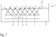
- FIG. 7 shows the use of a heat exchanger according to the invention as an evaporator.
- a heat exchanger 1 is completely or partially immersed in a sump 7 which is filled with a liquid 70 to be evaporated.
- the liquid 70 is evaporated by adding heat and leaves the sump as vapor 75.
- the evaporator can be part of a sorption heat pump.
- the heat transfer medium circulating in the pipe 10 supplies the heat necessary for evaporation.
- the heat transfer medium can be heated by a heat source (not shown) or, in the case of a refrigeration system, transport the heat to be dissipated.
- the height of the heat-conducting structure 2 between the joint on the tube 10 and the upper end can be between approximately 10 mm and approximately 100 mm or between approximately 10 mm and approximately 50 mm or approximately between 10 mm and approximately 30 mm.
- the sintered necks 24 between individual heat-conducting grids created during the heat treatment of the heat-conducting structure also form additional nucleation points for the formation of bubbles.
- the evaporation performance of a heat exchanger according to the invention can thus be significantly increased compared to known heat exchangers
Landscapes
- Physics & Mathematics (AREA)
- Engineering & Computer Science (AREA)
- Geometry (AREA)
- Thermal Sciences (AREA)
- Mechanical Engineering (AREA)
- General Engineering & Computer Science (AREA)
- Heat-Exchange Devices With Radiators And Conduit Assemblies (AREA)
Claims (15)
- Echangeur de chaleur (1) présentant au moins une surface de transfert de chaleur (100) reliée à une structure thermoconductrice (2), la structure thermoconductrice (2) comprenant au moins deux grilles thermoconductrices (20) qui sont reliées entre elles par coopération de matières,
caractérisé en ce que la structure thermoconductrice (2) présente une porosité d'environ 70 % à environ 90 %. - Echangeur de chaleur selon la revendication 1,
caractérisé en ce que les grilles thermoconductrices (20) sont sélectionnées parmi une couche de matériau perforée et/ou une grille en métal déployé et/ou un tressage et/ou un tricotage. - Echangeur de chaleur selon la revendication 1 ou 2,
caractérisé en ce que les grilles thermoconductrices (20) individuelles présentent une épaisseur de matériau inférieure à environ 200 µm ou inférieure à environ 150 µm ou inférieure à environ 60 µm. - Echangeur de chaleur selon l'une des revendications 1 à 3,
caractérisé en ce que la structure thermoconductrice (2) est disposée sur la surface de transfert de chaleur (100) de telle sorte que les grilles thermoconductrices (20) définissent avec le vecteur normal de la surface de transfert de chaleur un angle (β) d'environ 30° à environ 150° ou d'environ 70° à environ 110° ou d'environ 80° à environ 100° ou d'environ 90°. - Echangeur de chaleur selon l'une des revendications 1 à 4,
caractérisé en ce que la surface de transfert de chaleur (100) est une paroi tubulaire d'un tube (10) ou comprend une telle paroi. - Echangeur de chaleur selon l'une des revendications 1 à 5,
caractérisé en ce que la structure thermoconductrice (2) est fabriquée par frittage des grilles thermoconductrices (20). - Echangeur de chaleur selon l'une des revendications 1 à 6,
caractérisé en ce que la structure thermoconductrice (2) a une hauteur d'environ 1 mm à environ 10 mm ou d'environ 1 mm à environ 5 mm ou d'environ 1 mm à environ 3 mm ou d'environ 15 mm à environ 40 mm ou d'environ 20 mm à environ 30 mm. - Echangeur de chaleur selon l'une des revendications 1 à 7,
caractérisé en ce que la structure thermoconductrice (2) comprend ou est constituée d'environ 50 à environ 2500 ou d'environ 100 à environ 1000 ou d'environ 150 à environ 500 ou d'environ 200 à environ 300 grilles thermoconductrices (20). - Echangeur de chaleur selon l'une des revendications 1 à 8,
caractérisé en ce que la structure thermoconductrice (2) présente une porosité d'environ 80 % à environ 85 %. - Echangeur de chaleur selon l'une des revendications 1 à 9,caractérisé en ce que la taille des mailles (a, b) de la grille thermoconductrice (20) est comprise entre environ 1,5 mm et environ 3,5 mm, et/ouen ce que la largeur d'une âme (23) de la grille thermoconductrice (20) est comprise entre environ 180 µm et environ 50 µm.
- Echangeur de chaleur selon l'une des revendications 1 à 10,
caractérisé en ce que la conductivité thermique de la structure thermoconductrice (2) dans la direction du vecteur normal du plan défini par les grilles thermoconductrices (20) est inférieure de plus d'un facteur 7 ou de plus d'un facteur 8 ou de plus d'un facteur 10 à celle dans une direction orthogonale au vecteur normal. - Echangeur de chaleur selon l'une des revendications 1 à 11,
comprenant en outre un agent de sorption disposé sur et/ou dans la structure thermoconductrice (2). - Echangeur de chaleur selon l'une des revendications 1 à 12,caractérisé en ce que la structure thermoconductrice (2) est plissée, et/ouen ce que la structure thermoconductrice (2) est reliée au tube (10) par coopération de matières.
- Procédé d'évaporation d'un liquide,
caractérisé en ce qu'une structure thermoconductrice (2) d'un échangeur de chaleur (1) selon l'une des revendications 1 à 13 est immergée au moins partiellement dans un puisard, et au moins un tube (10) de l'échangeur de chaleur (1) est traversé par un premier fluide caloporteur (6). - Procédé de transfert de chaleur entre un premier fluide caloporteur (6) et un deuxième fluide caloporteur (5) au moyen d'un échangeur de chaleur (1),
caractérisé en ce qu'une structure thermoconductrice (2) d'un échangeur de chaleur (1) selon l'une des revendications 1 à 13 est traversée par le deuxième fluide caloporteur (5), et au moins un tube (10) de l'échangeur de chaleur (1) est traversé par le premier fluide caloporteur (6).
Applications Claiming Priority (2)
| Application Number | Priority Date | Filing Date | Title |
|---|---|---|---|
| DE102016224338.1A DE102016224338A1 (de) | 2016-12-07 | 2016-12-07 | Wärmeübertrager und Verfahren zu dessen Verwendung |
| PCT/EP2017/081648 WO2018104375A1 (fr) | 2016-12-07 | 2017-12-06 | Échangeur de chaleur et procédé d'utilisation de celui-ci |
Publications (2)
| Publication Number | Publication Date |
|---|---|
| EP3551957A1 EP3551957A1 (fr) | 2019-10-16 |
| EP3551957B1 true EP3551957B1 (fr) | 2024-02-14 |
Family
ID=60654957
Family Applications (1)
| Application Number | Title | Priority Date | Filing Date |
|---|---|---|---|
| EP17811925.1A Active EP3551957B1 (fr) | 2016-12-07 | 2017-12-06 | Échangeur de chaleur et procédé d'utilisation de celui-ci |
Country Status (3)
| Country | Link |
|---|---|
| EP (1) | EP3551957B1 (fr) |
| DE (1) | DE102016224338A1 (fr) |
| WO (1) | WO2018104375A1 (fr) |
Family Cites Families (12)
| Publication number | Priority date | Publication date | Assignee | Title |
|---|---|---|---|---|
| DE1451009A1 (de) * | 1963-07-10 | 1969-03-13 | Siemens Elektrogeraete Gmbh | Waermeaustauscher |
| FR2085171B1 (fr) * | 1969-12-23 | 1974-02-01 | Radial Ste Nle | |
| DE2714617C2 (de) * | 1977-04-01 | 1982-08-26 | Spiro Research B.V., Helmond | Wärmeaustauscher mit auf einem Trägerrohr angeordneter Drahtwendel |
| US5305824A (en) * | 1993-09-27 | 1994-04-26 | Gasseling John B | Oil filter cooler |
| EP0693666B1 (fr) * | 1994-07-22 | 1999-06-30 | Mitsubishi Denki Kabushiki Kaisha | Echangeur de chaleur pour un appareil de conditionnement d'air |
| DE29721686U1 (de) * | 1996-11-27 | 1998-01-22 | Joh. Vaillant Gmbh U. Co, 42859 Remscheid | Wärmetauscher |
| DE19961284A1 (de) * | 1999-12-18 | 2001-07-12 | Bosch Gmbh Robert | Wärmeübertrager für Gasheizgeräte, insbesondere Brennwertgeräte |
| US7981199B2 (en) * | 2005-12-19 | 2011-07-19 | Behr Gmbh & Co. Kg | Sorber heat exchanger wall and sorber heat exchanger |
| RU2311600C1 (ru) * | 2006-06-20 | 2007-11-27 | Владимир Сергеевич Попов | Трубчатый теплообменник (варианты) |
| DE102009018197A1 (de) * | 2008-04-24 | 2009-11-26 | Scheller, Gudrun Charlotte | Flächengebilde |
| FR2993967B1 (fr) * | 2012-07-24 | 2014-08-29 | Valeo Systemes Thermiques | Ailette destinee a perturber l'ecoulement d'un fluide, echangeur de chaleur comprenant une telle ailette et procede de fabrication d'une telle ailette |
| DE102014223250A1 (de) * | 2014-11-14 | 2016-05-19 | Vaillant Gmbh | Verdampfer-Wärmetauscher |
-
2016
- 2016-12-07 DE DE102016224338.1A patent/DE102016224338A1/de not_active Ceased
-
2017
- 2017-12-06 EP EP17811925.1A patent/EP3551957B1/fr active Active
- 2017-12-06 WO PCT/EP2017/081648 patent/WO2018104375A1/fr not_active Ceased
Also Published As
| Publication number | Publication date |
|---|---|
| EP3551957A1 (fr) | 2019-10-16 |
| WO2018104375A1 (fr) | 2018-06-14 |
| DE102016224338A1 (de) | 2018-06-07 |
Similar Documents
| Publication | Publication Date | Title |
|---|---|---|
| EP1987300B1 (fr) | Thermopompe a adsorption, refrigérateur a adsorption, et leurs éléments adsorbeurs | |
| EP1918668B1 (fr) | Dispositif destiné à la réception d'un fluide à l'aide de forces capillaires et procédé destiné à la fabrication du dispositif | |
| EP2414746B1 (fr) | Accumulateur de fluide de travail, échangeur de chaleur et pompe à chaleur | |
| WO2015028125A1 (fr) | Procédé de fabrication d'un échangeur de chaleur à plaques comportant plusieurs blocs d'échangeur de chaleur reliés par des supports recouverts de soudure | |
| EP2377596B9 (fr) | Dispositif de séchage à froid, notamment dispositif de séchage à froid à air comprimé, ainsi qu'échangeur de chaleur pour un dispositif de séchage à froid, notamment dispositif de séchage à froid à air comprimé | |
| DE112017000913B4 (de) | Kühlelement und Energiespeichermodul | |
| DE112014004473T5 (de) | Kältespeicher-Wärmetauscher | |
| DE10158387B4 (de) | Anordnung zur Kühlung von elektrischen Komponenten | |
| EP3027981B1 (fr) | Module d'adsorption | |
| DE202018103701U1 (de) | Metallische Kühlvorrichtung | |
| EP0106262B1 (fr) | Echangeur thermique en particulier radiateur | |
| EP3551957B1 (fr) | Échangeur de chaleur et procédé d'utilisation de celui-ci | |
| EP3708926A1 (fr) | Échangeur de chaleur et de substances par adsorption | |
| WO2018091567A1 (fr) | Structure d'échangeur de chaleur, procédé de fabrication et utilisation | |
| WO2018041416A1 (fr) | Procédé de fabrication d'un bloc d'échangeur thermique à plaques par application ciblée du matériau de soudure, en particulier sur les ailettes et sur les barres latérales | |
| DE3011011A1 (de) | Plattenwaermetauscher | |
| DE112018002936T5 (de) | Gestapelter Wärmetauscher und Verfahren zum Herstellen eines gestapelten Wärmetauschers | |
| DE102016222697B3 (de) | Wärmetauscher und Verfahren zu dessen Herstellung | |
| DE102019134587B4 (de) | Wärmeübertrager und Adsorptionsmaschine | |
| EP3333507A1 (fr) | Dispositif formant évaporateur | |
| DE2406432A1 (de) | Kuehleinrichtung mit chemischem verdampfungs-kuehlmittel | |
| DE202023001602U1 (de) | Lamellen-Wärmeübertrager | |
| AT202425B (de) | Verfahren zur Herstellung eines Rohrkühlers aus Aluminium oder Aluminiumlegierungen | |
| DE19728116A1 (de) | Wärmeübertrager zur Übertragung von Wärme zwischen einem Adsorbens und einem Wärmetransportmedium | |
| DE102024123866A1 (de) | Fallfilmwärmeübertrager für Stoff- und Wärmeübertragung in Sorptionswärmepumpen und Sorptionswärmepumpe bzw. -kältemaschine hiermit |
Legal Events
| Date | Code | Title | Description |
|---|---|---|---|
| STAA | Information on the status of an ep patent application or granted ep patent |
Free format text: STATUS: UNKNOWN |
|
| STAA | Information on the status of an ep patent application or granted ep patent |
Free format text: STATUS: THE INTERNATIONAL PUBLICATION HAS BEEN MADE |
|
| PUAI | Public reference made under article 153(3) epc to a published international application that has entered the european phase |
Free format text: ORIGINAL CODE: 0009012 |
|
| STAA | Information on the status of an ep patent application or granted ep patent |
Free format text: STATUS: REQUEST FOR EXAMINATION WAS MADE |
|
| 17P | Request for examination filed |
Effective date: 20190705 |
|
| AK | Designated contracting states |
Kind code of ref document: A1 Designated state(s): AL AT BE BG CH CY CZ DE DK EE ES FI FR GB GR HR HU IE IS IT LI LT LU LV MC MK MT NL NO PL PT RO RS SE SI SK SM TR |
|
| AX | Request for extension of the european patent |
Extension state: BA ME |
|
| RIN1 | Information on inventor provided before grant (corrected) |
Inventor name: SCHNABEL, LENA Inventor name: FINK, MARCEL Inventor name: ANDERSEN, OLAF Inventor name: ROHNE, MARCUS |
|
| DAV | Request for validation of the european patent (deleted) | ||
| DAX | Request for extension of the european patent (deleted) | ||
| STAA | Information on the status of an ep patent application or granted ep patent |
Free format text: STATUS: EXAMINATION IS IN PROGRESS |
|
| 17Q | First examination report despatched |
Effective date: 20200910 |
|
| RAP3 | Party data changed (applicant data changed or rights of an application transferred) |
Owner name: FRAUNHOFER-GESELLSCHAFT ZUR FOERDERUNG DER ANGEWANDTEN FORSCHUNG E.V. |
|
| GRAP | Despatch of communication of intention to grant a patent |
Free format text: ORIGINAL CODE: EPIDOSNIGR1 |
|
| STAA | Information on the status of an ep patent application or granted ep patent |
Free format text: STATUS: GRANT OF PATENT IS INTENDED |
|
| INTG | Intention to grant announced |
Effective date: 20231005 |
|
| GRAS | Grant fee paid |
Free format text: ORIGINAL CODE: EPIDOSNIGR3 |
|
| GRAA | (expected) grant |
Free format text: ORIGINAL CODE: 0009210 |
|
| STAA | Information on the status of an ep patent application or granted ep patent |
Free format text: STATUS: THE PATENT HAS BEEN GRANTED |
|
| AK | Designated contracting states |
Kind code of ref document: B1 Designated state(s): AL AT BE BG CH CY CZ DE DK EE ES FI FR GB GR HR HU IE IS IT LI LT LU LV MC MK MT NL NO PL PT RO RS SE SI SK SM TR |
|
| REG | Reference to a national code |
Ref country code: GB Ref legal event code: FG4D Free format text: NOT ENGLISH |
|
| REG | Reference to a national code |
Ref country code: CH Ref legal event code: EP |
|
| REG | Reference to a national code |
Ref country code: DE Ref legal event code: R096 Ref document number: 502017015836 Country of ref document: DE |
|
| REG | Reference to a national code |
Ref country code: IE Ref legal event code: FG4D Free format text: LANGUAGE OF EP DOCUMENT: GERMAN |
|
| REG | Reference to a national code |
Ref country code: LT Ref legal event code: MG9D |
|
| REG | Reference to a national code |
Ref country code: NL Ref legal event code: MP Effective date: 20240214 |
|
| PG25 | Lapsed in a contracting state [announced via postgrant information from national office to epo] |
Ref country code: IS Free format text: LAPSE BECAUSE OF FAILURE TO SUBMIT A TRANSLATION OF THE DESCRIPTION OR TO PAY THE FEE WITHIN THE PRESCRIBED TIME-LIMIT Effective date: 20240614 |
|
| PG25 | Lapsed in a contracting state [announced via postgrant information from national office to epo] |
Ref country code: LT Free format text: LAPSE BECAUSE OF FAILURE TO SUBMIT A TRANSLATION OF THE DESCRIPTION OR TO PAY THE FEE WITHIN THE PRESCRIBED TIME-LIMIT Effective date: 20240214 |
|
| PG25 | Lapsed in a contracting state [announced via postgrant information from national office to epo] |
Ref country code: GR Free format text: LAPSE BECAUSE OF FAILURE TO SUBMIT A TRANSLATION OF THE DESCRIPTION OR TO PAY THE FEE WITHIN THE PRESCRIBED TIME-LIMIT Effective date: 20240515 |
|
| PG25 | Lapsed in a contracting state [announced via postgrant information from national office to epo] |
Ref country code: HR Free format text: LAPSE BECAUSE OF FAILURE TO SUBMIT A TRANSLATION OF THE DESCRIPTION OR TO PAY THE FEE WITHIN THE PRESCRIBED TIME-LIMIT Effective date: 20240214 Ref country code: NL Free format text: LAPSE BECAUSE OF FAILURE TO SUBMIT A TRANSLATION OF THE DESCRIPTION OR TO PAY THE FEE WITHIN THE PRESCRIBED TIME-LIMIT Effective date: 20240214 Ref country code: RS Free format text: LAPSE BECAUSE OF FAILURE TO SUBMIT A TRANSLATION OF THE DESCRIPTION OR TO PAY THE FEE WITHIN THE PRESCRIBED TIME-LIMIT Effective date: 20240514 |
|
| PG25 | Lapsed in a contracting state [announced via postgrant information from national office to epo] |
Ref country code: ES Free format text: LAPSE BECAUSE OF FAILURE TO SUBMIT A TRANSLATION OF THE DESCRIPTION OR TO PAY THE FEE WITHIN THE PRESCRIBED TIME-LIMIT Effective date: 20240214 |
|
| PG25 | Lapsed in a contracting state [announced via postgrant information from national office to epo] |
Ref country code: RS Free format text: LAPSE BECAUSE OF FAILURE TO SUBMIT A TRANSLATION OF THE DESCRIPTION OR TO PAY THE FEE WITHIN THE PRESCRIBED TIME-LIMIT Effective date: 20240514 Ref country code: NO Free format text: LAPSE BECAUSE OF FAILURE TO SUBMIT A TRANSLATION OF THE DESCRIPTION OR TO PAY THE FEE WITHIN THE PRESCRIBED TIME-LIMIT Effective date: 20240514 Ref country code: NL Free format text: LAPSE BECAUSE OF FAILURE TO SUBMIT A TRANSLATION OF THE DESCRIPTION OR TO PAY THE FEE WITHIN THE PRESCRIBED TIME-LIMIT Effective date: 20240214 Ref country code: LT Free format text: LAPSE BECAUSE OF FAILURE TO SUBMIT A TRANSLATION OF THE DESCRIPTION OR TO PAY THE FEE WITHIN THE PRESCRIBED TIME-LIMIT Effective date: 20240214 Ref country code: IS Free format text: LAPSE BECAUSE OF FAILURE TO SUBMIT A TRANSLATION OF THE DESCRIPTION OR TO PAY THE FEE WITHIN THE PRESCRIBED TIME-LIMIT Effective date: 20240614 Ref country code: HR Free format text: LAPSE BECAUSE OF FAILURE TO SUBMIT A TRANSLATION OF THE DESCRIPTION OR TO PAY THE FEE WITHIN THE PRESCRIBED TIME-LIMIT Effective date: 20240214 Ref country code: GR Free format text: LAPSE BECAUSE OF FAILURE TO SUBMIT A TRANSLATION OF THE DESCRIPTION OR TO PAY THE FEE WITHIN THE PRESCRIBED TIME-LIMIT Effective date: 20240515 Ref country code: FI Free format text: LAPSE BECAUSE OF FAILURE TO SUBMIT A TRANSLATION OF THE DESCRIPTION OR TO PAY THE FEE WITHIN THE PRESCRIBED TIME-LIMIT Effective date: 20240214 Ref country code: ES Free format text: LAPSE BECAUSE OF FAILURE TO SUBMIT A TRANSLATION OF THE DESCRIPTION OR TO PAY THE FEE WITHIN THE PRESCRIBED TIME-LIMIT Effective date: 20240214 Ref country code: BG Free format text: LAPSE BECAUSE OF FAILURE TO SUBMIT A TRANSLATION OF THE DESCRIPTION OR TO PAY THE FEE WITHIN THE PRESCRIBED TIME-LIMIT Effective date: 20240214 |
|
| PG25 | Lapsed in a contracting state [announced via postgrant information from national office to epo] |
Ref country code: PT Free format text: LAPSE BECAUSE OF FAILURE TO SUBMIT A TRANSLATION OF THE DESCRIPTION OR TO PAY THE FEE WITHIN THE PRESCRIBED TIME-LIMIT Effective date: 20240614 Ref country code: PL Free format text: LAPSE BECAUSE OF FAILURE TO SUBMIT A TRANSLATION OF THE DESCRIPTION OR TO PAY THE FEE WITHIN THE PRESCRIBED TIME-LIMIT Effective date: 20240214 |
|
| PG25 | Lapsed in a contracting state [announced via postgrant information from national office to epo] |
Ref country code: SE Free format text: LAPSE BECAUSE OF FAILURE TO SUBMIT A TRANSLATION OF THE DESCRIPTION OR TO PAY THE FEE WITHIN THE PRESCRIBED TIME-LIMIT Effective date: 20240214 Ref country code: PT Free format text: LAPSE BECAUSE OF FAILURE TO SUBMIT A TRANSLATION OF THE DESCRIPTION OR TO PAY THE FEE WITHIN THE PRESCRIBED TIME-LIMIT Effective date: 20240614 Ref country code: PL Free format text: LAPSE BECAUSE OF FAILURE TO SUBMIT A TRANSLATION OF THE DESCRIPTION OR TO PAY THE FEE WITHIN THE PRESCRIBED TIME-LIMIT Effective date: 20240214 Ref country code: LV Free format text: LAPSE BECAUSE OF FAILURE TO SUBMIT A TRANSLATION OF THE DESCRIPTION OR TO PAY THE FEE WITHIN THE PRESCRIBED TIME-LIMIT Effective date: 20240214 |
|
| PG25 | Lapsed in a contracting state [announced via postgrant information from national office to epo] |
Ref country code: DK Free format text: LAPSE BECAUSE OF FAILURE TO SUBMIT A TRANSLATION OF THE DESCRIPTION OR TO PAY THE FEE WITHIN THE PRESCRIBED TIME-LIMIT Effective date: 20240214 |
|
| PG25 | Lapsed in a contracting state [announced via postgrant information from national office to epo] |
Ref country code: SM Free format text: LAPSE BECAUSE OF FAILURE TO SUBMIT A TRANSLATION OF THE DESCRIPTION OR TO PAY THE FEE WITHIN THE PRESCRIBED TIME-LIMIT Effective date: 20240214 |
|
| PG25 | Lapsed in a contracting state [announced via postgrant information from national office to epo] |
Ref country code: EE Free format text: LAPSE BECAUSE OF FAILURE TO SUBMIT A TRANSLATION OF THE DESCRIPTION OR TO PAY THE FEE WITHIN THE PRESCRIBED TIME-LIMIT Effective date: 20240214 Ref country code: CZ Free format text: LAPSE BECAUSE OF FAILURE TO SUBMIT A TRANSLATION OF THE DESCRIPTION OR TO PAY THE FEE WITHIN THE PRESCRIBED TIME-LIMIT Effective date: 20240214 |
|
| PG25 | Lapsed in a contracting state [announced via postgrant information from national office to epo] |
Ref country code: SK Free format text: LAPSE BECAUSE OF FAILURE TO SUBMIT A TRANSLATION OF THE DESCRIPTION OR TO PAY THE FEE WITHIN THE PRESCRIBED TIME-LIMIT Effective date: 20240214 |
|
| PG25 | Lapsed in a contracting state [announced via postgrant information from national office to epo] |
Ref country code: SM Free format text: LAPSE BECAUSE OF FAILURE TO SUBMIT A TRANSLATION OF THE DESCRIPTION OR TO PAY THE FEE WITHIN THE PRESCRIBED TIME-LIMIT Effective date: 20240214 Ref country code: SK Free format text: LAPSE BECAUSE OF FAILURE TO SUBMIT A TRANSLATION OF THE DESCRIPTION OR TO PAY THE FEE WITHIN THE PRESCRIBED TIME-LIMIT Effective date: 20240214 Ref country code: RO Free format text: LAPSE BECAUSE OF FAILURE TO SUBMIT A TRANSLATION OF THE DESCRIPTION OR TO PAY THE FEE WITHIN THE PRESCRIBED TIME-LIMIT Effective date: 20240214 Ref country code: EE Free format text: LAPSE BECAUSE OF FAILURE TO SUBMIT A TRANSLATION OF THE DESCRIPTION OR TO PAY THE FEE WITHIN THE PRESCRIBED TIME-LIMIT Effective date: 20240214 Ref country code: DK Free format text: LAPSE BECAUSE OF FAILURE TO SUBMIT A TRANSLATION OF THE DESCRIPTION OR TO PAY THE FEE WITHIN THE PRESCRIBED TIME-LIMIT Effective date: 20240214 Ref country code: CZ Free format text: LAPSE BECAUSE OF FAILURE TO SUBMIT A TRANSLATION OF THE DESCRIPTION OR TO PAY THE FEE WITHIN THE PRESCRIBED TIME-LIMIT Effective date: 20240214 |
|
| REG | Reference to a national code |
Ref country code: DE Ref legal event code: R097 Ref document number: 502017015836 Country of ref document: DE |
|
| PG25 | Lapsed in a contracting state [announced via postgrant information from national office to epo] |
Ref country code: IT Free format text: LAPSE BECAUSE OF FAILURE TO SUBMIT A TRANSLATION OF THE DESCRIPTION OR TO PAY THE FEE WITHIN THE PRESCRIBED TIME-LIMIT Effective date: 20240214 |
|
| PLBE | No opposition filed within time limit |
Free format text: ORIGINAL CODE: 0009261 |
|
| STAA | Information on the status of an ep patent application or granted ep patent |
Free format text: STATUS: NO OPPOSITION FILED WITHIN TIME LIMIT |
|
| PG25 | Lapsed in a contracting state [announced via postgrant information from national office to epo] |
Ref country code: IT Free format text: LAPSE BECAUSE OF FAILURE TO SUBMIT A TRANSLATION OF THE DESCRIPTION OR TO PAY THE FEE WITHIN THE PRESCRIBED TIME-LIMIT Effective date: 20240214 |
|
| PGFP | Annual fee paid to national office [announced via postgrant information from national office to epo] |
Ref country code: DE Payment date: 20241216 Year of fee payment: 8 |
|
| 26N | No opposition filed |
Effective date: 20241115 |
|
| PG25 | Lapsed in a contracting state [announced via postgrant information from national office to epo] |
Ref country code: SI Free format text: LAPSE BECAUSE OF FAILURE TO SUBMIT A TRANSLATION OF THE DESCRIPTION OR TO PAY THE FEE WITHIN THE PRESCRIBED TIME-LIMIT Effective date: 20240214 |
|
| PG25 | Lapsed in a contracting state [announced via postgrant information from national office to epo] |
Ref country code: MC Free format text: LAPSE BECAUSE OF FAILURE TO SUBMIT A TRANSLATION OF THE DESCRIPTION OR TO PAY THE FEE WITHIN THE PRESCRIBED TIME-LIMIT Effective date: 20240214 |
|
| REG | Reference to a national code |
Ref country code: CH Ref legal event code: PL |
|
| PG25 | Lapsed in a contracting state [announced via postgrant information from national office to epo] |
Ref country code: LU Free format text: LAPSE BECAUSE OF NON-PAYMENT OF DUE FEES Effective date: 20241206 |
|
| GBPC | Gb: european patent ceased through non-payment of renewal fee |
Effective date: 20241206 |
|
| REG | Reference to a national code |
Ref country code: BE Ref legal event code: MM Effective date: 20241231 |
|
| PG25 | Lapsed in a contracting state [announced via postgrant information from national office to epo] |
Ref country code: BE Free format text: LAPSE BECAUSE OF NON-PAYMENT OF DUE FEES Effective date: 20241231 Ref country code: GB Free format text: LAPSE BECAUSE OF NON-PAYMENT OF DUE FEES Effective date: 20241206 |
|
| PG25 | Lapsed in a contracting state [announced via postgrant information from national office to epo] |
Ref country code: FR Free format text: LAPSE BECAUSE OF NON-PAYMENT OF DUE FEES Effective date: 20241231 |
|
| PG25 | Lapsed in a contracting state [announced via postgrant information from national office to epo] |
Ref country code: CH Free format text: LAPSE BECAUSE OF NON-PAYMENT OF DUE FEES Effective date: 20241231 |
|
| PG25 | Lapsed in a contracting state [announced via postgrant information from national office to epo] |
Ref country code: IE Free format text: LAPSE BECAUSE OF NON-PAYMENT OF DUE FEES Effective date: 20241206 |
|
| REG | Reference to a national code |
Ref country code: AT Ref legal event code: MM01 Ref document number: 1657350 Country of ref document: AT Kind code of ref document: T Effective date: 20241206 |
|
| PG25 | Lapsed in a contracting state [announced via postgrant information from national office to epo] |
Ref country code: CY Free format text: LAPSE BECAUSE OF FAILURE TO SUBMIT A TRANSLATION OF THE DESCRIPTION OR TO PAY THE FEE WITHIN THE PRESCRIBED TIME-LIMIT; INVALID AB INITIO Effective date: 20171206 |
|
| PG25 | Lapsed in a contracting state [announced via postgrant information from national office to epo] |
Ref country code: AT Free format text: LAPSE BECAUSE OF NON-PAYMENT OF DUE FEES Effective date: 20241206 |