EP3552287B1 - Procédé de coupure d'un arc électrique dans une installation électrique - Google Patents
Procédé de coupure d'un arc électrique dans une installation électrique Download PDFInfo
- Publication number
- EP3552287B1 EP3552287B1 EP17808078.4A EP17808078A EP3552287B1 EP 3552287 B1 EP3552287 B1 EP 3552287B1 EP 17808078 A EP17808078 A EP 17808078A EP 3552287 B1 EP3552287 B1 EP 3552287B1
- Authority
- EP
- European Patent Office
- Prior art keywords
- circuit breaker
- measuring
- electrical installation
- current
- electrical
- Prior art date
- Legal status (The legal status is an assumption and is not a legal conclusion. Google has not performed a legal analysis and makes no representation as to the accuracy of the status listed.)
- Active
Links
Images


Classifications
-
- H—ELECTRICITY
- H02—GENERATION; CONVERSION OR DISTRIBUTION OF ELECTRIC POWER
- H02H—EMERGENCY PROTECTIVE CIRCUIT ARRANGEMENTS
- H02H1/00—Details of emergency protective circuit arrangements
- H02H1/0007—Details of emergency protective circuit arrangements concerning the detecting means
- H02H1/0015—Using arc detectors
- H02H1/0023—Using arc detectors sensing non electrical parameters, e.g. by optical, pneumatic, thermal or sonic sensors
-
- H—ELECTRICITY
- H02—GENERATION; CONVERSION OR DISTRIBUTION OF ELECTRIC POWER
- H02B—BOARDS, SUBSTATIONS OR SWITCHING ARRANGEMENTS FOR THE SUPPLY OR DISTRIBUTION OF ELECTRIC POWER
- H02B1/00—Frameworks, boards, panels, desks, casings; Details of substations or switching arrangements
- H02B1/26—Casings; Parts thereof or accessories therefor
- H02B1/30—Cabinet-type casings; Parts thereof or accessories therefor
- H02B1/306—Accessories, e.g. windows
-
- H—ELECTRICITY
- H02—GENERATION; CONVERSION OR DISTRIBUTION OF ELECTRIC POWER
- H02B—BOARDS, SUBSTATIONS OR SWITCHING ARRANGEMENTS FOR THE SUPPLY OR DISTRIBUTION OF ELECTRIC POWER
- H02B13/00—Arrangement of switchgear in which switches are enclosed in, or structurally associated with, a casing, e.g. cubicle
- H02B13/02—Arrangement of switchgear in which switches are enclosed in, or structurally associated with, a casing, e.g. cubicle with metal casing
- H02B13/025—Safety arrangements, e.g. in case of excessive pressure or fire due to electrical defect
-
- G—PHYSICS
- G01—MEASURING; TESTING
- G01V—GEOPHYSICS; GRAVITATIONAL MEASUREMENTS; DETECTING MASSES OR OBJECTS; TAGS
- G01V3/00—Electric or magnetic prospecting or detecting; Measuring magnetic field characteristics of the earth, e.g. declination, deviation
- G01V3/08—Electric or magnetic prospecting or detecting; Measuring magnetic field characteristics of the earth, e.g. declination, deviation operating with magnetic or electric fields produced or modified by objects or geological structures or by detecting devices
-
- H—ELECTRICITY
- H01—ELECTRIC ELEMENTS
- H01H—ELECTRIC SWITCHES; RELAYS; SELECTORS; EMERGENCY PROTECTIVE DEVICES
- H01H83/00—Protective switches, e.g. circuit-breaking switches, or protective relays operated by abnormal electrical conditions otherwise than solely by excess current
- H01H83/14—Protective switches, e.g. circuit-breaking switches, or protective relays operated by abnormal electrical conditions otherwise than solely by excess current operated by imbalance of two or more currents or voltages, e.g. for differential protection
-
- H—ELECTRICITY
- H01—ELECTRIC ELEMENTS
- H01H—ELECTRIC SWITCHES; RELAYS; SELECTORS; EMERGENCY PROTECTIVE DEVICES
- H01H83/00—Protective switches, e.g. circuit-breaking switches, or protective relays operated by abnormal electrical conditions otherwise than solely by excess current
- H01H83/20—Protective switches, e.g. circuit-breaking switches, or protective relays operated by abnormal electrical conditions otherwise than solely by excess current operated by excess current as well as by some other abnormal electrical condition
-
- H—ELECTRICITY
- H01—ELECTRIC ELEMENTS
- H01H—ELECTRIC SWITCHES; RELAYS; SELECTORS; EMERGENCY PROTECTIVE DEVICES
- H01H9/00—Details of switching devices, not covered by groups H01H1/00 - H01H7/00
- H01H9/50—Means for detecting the presence of an arc or discharge
-
- H—ELECTRICITY
- H02—GENERATION; CONVERSION OR DISTRIBUTION OF ELECTRIC POWER
- H02H—EMERGENCY PROTECTIVE CIRCUIT ARRANGEMENTS
- H02H3/00—Emergency protective circuit arrangements for automatic disconnection directly responsive to an undesired change from normal electric working condition with or without subsequent reconnection ; integrated protection
- H02H3/08—Emergency protective circuit arrangements for automatic disconnection directly responsive to an undesired change from normal electric working condition with or without subsequent reconnection ; integrated protection responsive to excess current
-
- H—ELECTRICITY
- H02—GENERATION; CONVERSION OR DISTRIBUTION OF ELECTRIC POWER
- H02H—EMERGENCY PROTECTIVE CIRCUIT ARRANGEMENTS
- H02H5/00—Emergency protective circuit arrangements for automatic disconnection directly responsive to an undesired change from normal non-electric working conditions with or without subsequent reconnection
- H02H5/12—Emergency protective circuit arrangements for automatic disconnection directly responsive to an undesired change from normal non-electric working conditions with or without subsequent reconnection responsive to undesired approach to, or touching of, live parts by living beings
Definitions
- the invention relates to an electrical system with a switch cabinet, a circuit breaker arranged in the switch cabinet and at least one optical triggering device operatively connected to the circuit breaker, which is designed to trigger or switch off the circuit breaker when an arc is optically detected.
- the invention further relates to a method for protecting an electrical system and operating personnel located in or on the electrical system, wherein the electrical system comprises a switch cabinet, a circuit breaker arranged in the switch cabinet and at least one optical triggering device operatively connected to the circuit breaker, which triggers or switches off the circuit breaker when an arc is detected.
- Such a method and such a device are known in principle and are used, for example, to protect people and/or the system itself from the destructive effects of an arc caused by a short circuit or at least to mitigate its effects.
- animals or falling tools as well as (wet) dirt can reduce the insulation or the spark gap between two conductors at different voltage potentials to such an extent that such an arc is created.
- the sometimes very high resulting currents can lead to violent Explosions can occur due to the air heating up in a short period of time.
- the optical triggering devices for switching off or triggering a circuit breaker are permanently installed in the control cabinet and monitor sensitive areas there.
- the light emanating from a monitoring area can be guided to the optical triggering device via a fiber optic cable.
- the EP 2 696460 A1 discloses a switch cabinet comprising several busbars and circuit breakers. At least one of the circuit breakers contains a trip unit with an interface to an arc fault sensor, which is assigned to the switch cabinet The trip unit trips at least one of the circuit breakers and a short-circuit switch when an appropriate current flows through the circuit breaker and an arc fault signal is present from the arc fault sensor.
- the EP 2 424 059 A2 also discloses a protective device for an electrical circuit with a current sensor for measuring a current through a conductor of the electrical circuit and a voltage sensor for measuring a voltage across a plurality of conductors of the electrical circuit.
- the protective device further comprises a control device which is connected to the current sensor and the voltage sensor and activates a first protective device or a second protective device for the electrical circuit depending on the values received.
- Mobile optical triggering devices for switching off or triggering a circuit breaker are also known. These are usually used temporarily and can also be arranged outside the control cabinet.
- an optical triggering device can be worn by a person to protect them. If the optical triggering device worn by the person detects an arc, the circuit breaker is switched off or triggered and protects the person from the effects of the arc. In this way, for example, electrical systems or control cabinets can be protected that otherwise have no protection against the occurrence of an arc, or areas of electrical systems or control cabinets can be protected that otherwise have no protection against the occurrence of an arc.
- the problem is that the optical triggering device, which is located outside the control cabinet, is usually in an environment that is difficult to assess. For example, events other than an arc can lead to false triggering of the circuit breaker, such as bright flashes of light that do not pose any danger in themselves.
- arcs can also occur in electrical systems during normal operation, for example in the form of switching arcs when a live switching contact is separated.
- the switching arc can be directly visible and/or luminous gas can escape from the switching device, which comes from the burning switching contacts or arc-conducting or arc-extinguishing plates of the switching device.
- the switching device coupled or operatively connected to the optical triggering device is switched off/triggered, regardless of whether the flash of light poses a potential danger and regardless of whether the switching device assigned to the optical triggering device can influence the flash of light at all, i.e. extinguish it.
- One task is therefore to provide an improved electrical system and an improved method for operating such a system.
- a dangerous arc should be reliably detected and unnecessary shutdown of an electrical system should be avoided.
- the object of the invention is further achieved by a method of the type mentioned at the outset, in which the circuit breaker is only triggered or switched off by the at least one optical triggering device when a Access to a secured area of the electrical system is detected by detecting the presence of at least one optical triggering device in a danger area of the electrical system, wherein an operative connection between the circuit breaker and the optical triggering device is established wirelessly.
- the optical triggering device is in the danger zone, it is generally possible to switch off the circuit breaker using at least one optical triggering device. If the optical triggering device is outside the danger zone, this is not possible.
- a switching arc inside a closed switch cabinet or at a sufficient distance is harmless in itself, but if the person is, for example, in the immediate vicinity of the arc with their head, this can result in serious health problems. Consequences result.
- the optical detection of an arc as such is known per se and can be based, for example, on the intensity and/or the spectral distribution of the received light.
- the detection device is designed as a wireless detection receiver or is connected to a wireless detection receiver and is designed to detect the optical triggering device as being present in a danger zone when a transmission signal caused by the optical triggering device causes a reception field strength in the detection receiver that is above a field strength threshold. Accordingly, the circuit breaker is only switched off or triggered by the optical triggering device when the optical triggering device is detected as being present in a danger zone, i.e. when a transmission signal caused by the optical triggering device causes a reception field strength in the detection receiver that is above a field strength threshold.
- the danger zone in which the optical triggering device must be located in order to be able to trigger the circuit breaker does not necessarily have to coincide with the reception range of a wireless receiver coupled to the switching input of the circuit breaker. For correct functioning, it is necessary that the reception range of the receiver coupled to the circuit breaker covers the danger area, but it can also extend beyond it.
- access in the context of the invention is synonymous with the term “access”. This means that walking is possible for access to a secured area of the electrical system, but strictly speaking it is not necessary.
- the at least one (first) optical triggering device can be arranged in particular on a helmet, an armband and/or on an item of clothing, in particular on a jacket.
- the optical triggering device can, for example, be fixedly arranged on the helmet, armband and/or on the item of clothing, or it can be temporarily mounted on the items mentioned, for example with a clip or a Velcro strip, if required.
- the (second) optical triggering device can also have a clip, or for example a magnet, with which the optical triggering device can be attached to metal components.
- the electronic circuit is designed as a logical AND link between a positive arc signal from the optical triggering device and an access signal from the detection device or acts as such and is operatively connected to the circuit breaker on the output side.
- the AND link is therefore logically connected between the Circuit breaker and the optical triggering device. Accordingly, a positive arc signal from the optical triggering device and an access signal from the detection device are logically ANDed, and the circuit breaker is only switched off or triggered by the optical triggering device when access to the electrical system is detected.
- the circuit breaker is only triggered or switched off by the at least one optical triggering device if a measured current through the circuit breaker or through the electrical system exceeds an operating current threshold value and/or the time derivative of the measured operating current exceeds a rise threshold value.
- a second criterion is used to classify an event as an arc. Specifically, not only the light emitted by the arc is evaluated (namely by the optical triggering device), but also the Circuit breaker or current flowing through the electrical system. A flash, for example, cannot switch off the circuit breaker because this does not result in an increase in current through the electrical system. The probability of a false alarm is therefore significantly reduced.
- the circuit breaker is designed as a miniature circuit breaker, as an arc short-circuit switch or as a combined miniature and arc short-circuit switch. These switches are often already present in an electrical system for other purposes and are used by the proposed system, which results in a double benefit.
- Miniature circuit breakers are generally used to disconnect a circuit when an overload is detected. Overload usually occurs when there is excess current, particularly in connection with a certain current increase, and/or when there is excess temperature, i.e. when there is thermal overload.
- Arc short-circuit switches are used to short-circuit two or more conductors at different voltage potentials (for example the phases and possibly a neutral conductor) in order to extinguish a burning arc.
- Arc short-circuit switches are generally used in combination with an upstream miniature circuit breaker, which creates a switch cascade. If the arc short-circuit switch is closed, short-circuit currents usually occur that are so high that they cause the circuit breaker to be switched off or tripped.
- the two switches can generally also be designed as a combined line and arc short-circuit switch.
- the switching cascade mentioned above can be effective, or the two switches can also be operated simultaneously in the event of danger.
- An active connection to the optical triggering device can now be connected to a circuit breaker and switch it off/trip it directly, or the active connection can also be connected to the arc short-circuit switch and close it in the event of danger.
- the arc "simulated" in this way subsequently leads to the tripping of an upstream circuit breaker if this is not already switched simultaneously with the arc short-circuit switch (if, for example, a combined circuit and arc short-circuit switch is used).
- the optical triggering device can therefore be actively connected to an arc fault protection system.
- a person may be at risk not only from an arc (fault) occurring in the electrical system, but also, for example, from a fault current that is too high due to faulty insulation.
- the measures suggested above not only protect a person from an arc, but also from the harmful effects of a fault current that is too high.
- this switch-off can be based on a different (in particular a lower) fault current than a fault current that is permitted during normal operation of the electrical system without a person being present.
- the fault current is determined by measuring the voltage between the measuring electrodes.
- the fault current flows through the person in the electrical system, for example through their arm, and causes a voltage drop between the measuring electrodes due to the resistance of the human body (approximately 800 ohms). If the measured value, i.e. the measured voltage, exceeds a certain threshold value, which is associated with a risk to people from the corresponding fault current, the circuit from which the risk emanates is disconnected from the supply voltage.
- the measuring electrodes are electrically connected to one another, preferably by means of an electrical conductor whose resistance is lower than that of the human body.
- the fault current then flows, at least between the two measuring electrodes, mainly through the electrical conductor, thus protecting the person in the electrical installation.
- the current measuring device can have a current measuring resistor that is electrically connected to the measuring electrodes or a through-hole transformer, which can also be designed as a current clamp.
- the fault current is determined via the electrical voltage that drops across the current measuring resistor.
- the electrical system basically has a voltage measuring device. The boundaries between voltage measuring device and current measuring device are therefore fluid.
- an electromagnetic field is determined that is caused by the current flowing between the measuring electrodes. The With this measuring method, the connection between the two measuring electrodes can be made particularly low-resistance.
- an item of clothing worn by the person in the electrical installation has electrical conductors.
- the item of clothing can be designed as a glove, jacket, overalls, trousers or protective suit, and the electrical conductors can be formed by electrically conductive wires, an electrically conductive mesh and/or an electrically conductive foil, in particular by metallic wires, a metallic mesh and/or a metallic foil or by carbon wires, a carbon-wire mesh and/or a carbon foil.
- the electrical conductors are incorporated into the item of clothing and preferably do not touch the skin of the person in the electrical installation. For example, a layer of cotton fabric or another electrically insulating material is placed between the skin and the conductors. Although insulation between the electrical conductors and the person is advantageous, the electrical conductors can nevertheless also rest on the skin of the person in the electrical installation.
- the fault current flows mainly through the electrical conductors and only to a small extent through the person in the electrical installation, which in turn protects the person.
- the current measurement itself can be carried out using a current measuring resistor connected to the electrical conductors of the item of clothing, or using a through-hole transformer which measures an electromagnetic field generated by a caused by current flowing through the electrical conductor of the garment.
- cases d) to f) can be applied individually or in combination in an electrical system. It is particularly advantageous if cases d) and f) are combined, or cases e) and f).
- cases d) and f) are combined, or cases e) and f).
- people in an electrical system should wear protective clothing, which can be equipped with electrical conductors, as in case f). If the person touches conductive parts of the electrical system, a fault current, as explained above, flows mainly via the electrical conductors of the protective clothing and only to a small extent via the body of the person in the electrical system, thus protecting them. Contrary to the recommendations or regulations of the operators of the electrical systems, however, the protective clothing is not worn for a time.
- the The threshold value intended for triggering or switching off the circuit breaker is a voltage threshold value (if a voltage measuring device is used) or a current threshold value (if a current measuring device is used).
- the term “threshold value” is used for simplicity, which can be replaced by the term “voltage threshold value” or “current threshold value” depending on the application.
- the voltage measuring device / current measuring device and the optical triggering device are connected to the same circuit breaker.
- the advantage of the proposed measures then becomes particularly apparent, or a particular synergistic benefit arises, since one circuit breaker can be used to avert the dangers of two different types of fault.
- the circuit breaker as mentioned at the beginning, is often already present in an electrical system and switches off in the event of an overcurrent, for example (circuit breaker).
- the optical triggering device could also be operatively connected to a different circuit breaker than the voltage measuring device/current measuring device.
- circuit breakers, arc short-circuit switches or combined circuit and arc short-circuit switches are possible.
- the voltage measuring device/current measuring device is operatively connected to a first group of circuit breakers and the optical triggering device to a second group of circuit breakers.
- the two groups can also have an overlap. It is advantageous if the measuring electrodes in cases d) and e) are designed for attachment to the human body, in particular to the skin of the human body.
- the measuring electrodes for carrying out the disclosed method are attached to the human body, in particular to the skin of the human body, and in case d) the voltage drop between the measuring electrodes on said body is determined or in case e) the current flowing between the measuring electrodes is determined. If a person (unintentionally) touches parts of the electrical system that carry a dangerous voltage, an electric current flows through the human body, and in particular through the arm that is touching it, which causes a voltage drop between the measuring electrodes due to the resistance of the human body (approximately 800 ohms). If the measured value (i.e. the measured voltage or the measured current) exceeds a certain threshold value, which is associated with a risk to humans due to the corresponding fault current, the circuit from which the risk emanates is disconnected from a supply voltage as described above.
- a certain threshold value which is associated with a risk to humans due to the corresponding fault current
- the electrical system can also have several pairs of electrodes, so that, for example, a worker can be equipped with several measuring electrodes, or so that several workers can be equipped with measuring electrodes.
- one of the two measuring electrodes in cases d) and e) is connected to an earth potential or the human body in question is connected to an earth potential using an earth electrode and/or in case f) the electrical conductors of the item of clothing are connected to an earth potential. Accordingly, it is also advantageous if one of the two measuring electrodes in cases d) and e) is connected to an earth potential or the electrical system has an earth electrode connected to an earth potential which is designed to be attached to the human body, in particular to the skin of the human body, and/or in case f) the electrical conductors of the item of clothing are connected to an earth potential.
- the earth electrode can in particular be arranged on an armband or a leg bandage.
- the measuring electrodes and/or the earthing electrode are arranged on the inside of a piece of clothing, in particular on a jacket, trousers, a shoe and/or a glove. In this way, both the worker and the measuring electrodes are well protected.
- tension bands can be attached to the outside of the piece of clothing in question so that the measuring electrodes and/or the earthing electrode can be pressed firmly onto the skin of the human body. In this way, a type of arm or Leg bandage.
- the measuring electrodes, the bandages, the electrical conductors as well as the voltage measuring device and the current measuring device can in particular be part of the same garment.
- control cabinet is designed for an operating current of at least 250 amps and/or for an operating voltage of a maximum of 1000 VAC or 1500 VDC. These areas characterize high-current systems or low-voltage systems.
- the arrangement presented is particularly suitable for this type of electrical system.
- the Fig.1 shows an electrical system 1a, comprising a switch cabinet 2a and a circuit breaker 3 arranged in the switch cabinet 2a.
- the switch cabinet 2a can be designed in particular for an operating current of at least 250 amperes and/or for an operating voltage of a maximum of 1000 VAC or 1500 VDC.
- the electrical system 1a has several optical triggering devices 4a, 4b which are operatively connected to the circuit breaker 3 and which are designed to trigger or switch off the circuit breaker 3 when an arc is detected.
- the electrical system 1a has a detection device 5 for detecting access to a secured area of the electrical system 1a, as well as an electronic circuit 6 which is connected to the detection device 5 and enables the circuit breaker 3 to be triggered or switched off by the optical triggering devices 4a, 4b when access is detected and otherwise prevents it.
- the circuit breaker 3 can have a switching input for triggering or switching off the circuit breaker 3.
- the optical triggering device 4a, 4b can have a control output which is (actively) connected to the switching input of the circuit breaker 3. When an arc is detected, the optical triggering device 4a, 4b changes the state of the control output and subsequently triggers the circuit breaker 3.
- first optical triggering devices 4a are provided for attachment to the human Body, and a second optical triggering device 4b is arranged on the outside of the control cabinet 2a.
- the first optical triggering devices 4a can, as shown in the Fig.1 shown, be arranged on a helmet 7, an armband and/or on an item of clothing 8 and worn by a person 9.
- a special protective vest 8 is provided as the item of clothing, but it is also conceivable that the first optical triggering devices 4a are arranged on a jacket or trousers.
- a control cabinet door 10 is shown, which in the example shown is completely open and can therefore only be seen from its narrow side.
- a positive arc signal from the optical triggering devices 4a, 4b and an access signal from the detection device 5 are logically ANDed.
- the electronic circuit 6, which is operatively connected to the circuit breaker 3 on the output side, can therefore be designed as a logical AND connection or at least act as such.
- the AND connection is thus logically inserted between the circuit breaker 3 and the optical triggering devices 4a, 4b.
- the proposed measures ensure that the optical triggering devices 4a, 4b only trigger the circuit breaker 3 if there is actually a danger from the secured area. If, however, there is no danger from the secured area, the optical triggering devices 4a, 4b cannot trigger the circuit breaker 3. This prevents safety-critical circuits from being triggered due to an alleged In an emergency and without actual danger to the person 9 can be switched off.
- the active connection between the circuit breaker 3 and the optical triggering devices 4a, 4b is established wirelessly.
- the control output of the optical triggering devices 4a in this example is connected to a wireless transmitter 11a and the switching input of the circuit breaker 3 to a wireless receiver 11b.
- the wireless transmitter 11a and the wireless receiver 11b are designed to establish a wireless (active) connection.
- a separate transmitter 11a and a separate receiver 11b are provided. It would of course also be conceivable that the transmitter(s) 11a are integrated into the optical triggering devices 4a and/or the receiver 11b into the circuit breaker 3.
- first optical triggering devices 4a distributed all around the person 9 and a second optical triggering device 4b are arranged on the outside of the control cabinet 2a, which is aligned with the interior of the control cabinet 2a. It would also be conceivable for the second triggering device 4b to be arranged inside the control cabinet 2a or for several second triggering devices 4b to be provided. It is equally conceivable for only one first optical triggering device 4a to be provided and for example to be attached to the helmet 7, which can be aligned in particular in the direction of view of the person 9. Of course, the system can also be designed for more than one person 9. By providing first and second optical triggering devices 4a and 4b, the In any case, Person 9 is very well protected from any arcing that might occur.
- first optical triggering devices 4a are arranged on the person 9 (and a second optical triggering device 4b is missing on or in the control cabinet 2a), or that only at least one second optical triggering device 4b is arranged on or in the control cabinet 2a (and a first optical triggering device 4a is missing on the person 9).
- the system is then constructed more simply and functions in the manner already described above.
- the detection device 5 is designed to detect the presence of the optical triggering devices 4a, 4b in a danger zone A of the electrical system 1a, and the electronic circuit 6 connected to the detection device 5 enables the circuit breaker 3 to be triggered or switched off by the optical triggering devices 4a, 4b when the optical triggering devices 4a, 4b are present in the danger zone A, and otherwise prevents this.
- the detection device 5 can be designed as a wireless detection receiver or connected to a wireless detection receiver.
- the detection device 5 can be connected to the wireless receiver 11b or implemented by it.
- the optical triggering devices 4a, 4b are then recognized as being present in a danger area A if a transmission signal caused by the optical triggering devices 4a, 4b has a field strength above a threshold value. Reception field strength in the detection receiver.
- the danger area A in which the optical triggering devices 4a, 4b must be located in order to be able to trigger the circuit breaker 3 does not necessarily have to coincide with the reception area of the wireless receiver 11b coupled to the switching input of the circuit breaker 3. For correct functioning, it is necessary that the said reception area of the receiver 11b covers the danger area A, but it can also extend beyond it.
- the circuit breaker 3 can be designed as a circuit breaker, as an arc short-circuit switch or as a combined circuit breaker and arc short-circuit switch. These switches are often already present in an electrical system 1a for other purposes and are used by the proposed system, resulting in a double benefit.
- Fig. 2 shows the operating principle of a switching cascade, which has several arc short-circuit switches 12a..12c and a higher-level circuit breaker 13.
- Fig. 2 further shows the purely symbolic exemplary control cabinet 2 with a device 14 for detecting an arc, which is connected to a light-sensitive element 15a and a current measuring loop 15b or a through-hole converter 15b.
- the said device 14 has a switching output 16.
- circuit breakers 17a..17c are provided, each assigned to a phase of a three-phase system. Finally, three consumers 18a..18c are connected to the control cabinet 2.
- circuit breaker 13 and/or the circuit breakers 17a..17c do not trip via the overcurrent, but directly via the signal at the output 16, which is then also fed to the inputs of the circuit breaker 13 and/or the circuit breakers 17a..17c.
- an arc L is present when a bright light is emitted via the light-sensitive element 15a.
- Light is measured AND when the operating current measured by the current measuring loop 15b exceeds an operating current threshold value.
- the current measuring loop 15b therefore acts as an operating current measuring device 15b.
- additional or other criteria can also be used to determine whether an arc L is present or not.
- the optical triggering devices 4a, 4b of the Fig.1 can now be directly connected to the circuit breaker 13 / the circuit breakers 17a..17c and control them.
- the optical triggering devices 4a, 4b can also be directly connected to the arc short-circuit switches 12a..12c and control them, provided that arc short-circuit switches 12a..12c are installed in the control cabinet 2a.
- the circuit breakers 13, 17a..17c can be indirectly triggered by the cascade effect described above, or the circuit breakers 13, 17a..17c are also directly controlled by the optical triggering devices 4a, 4b.
- the optical triggering devices 4a, 4b can thus be directly connected to an arc fault protection system.
- the detection of an electric arc can also be carried out in the electrical system 1a according to Fig.1 be purely optical, or an operating current measuring device 15b is provided for measuring a current flowing through the circuit breaker 3, 13, 17a..17b or through the electrical system 1a, as well as an electronic circuit 14 which is connected to the operating current measuring device 15b and triggers or switches off the circuit breaker 3, 13, 17a..17b by the optical triggering device 4a, 4b only when a Operating current threshold value by the measured current and/or when a rise threshold value is exceeded, a time derivative of the measured current is possible.
- both a higher-level circuit breaker 13 and circuit breakers 17a..17c assigned to each phase of a three-phase system are provided. If the arrangement has the same or a comparable function, only the higher-level circuit breaker 13 can be provided or only the circuit breakers 17a..17c assigned to each phase of a three-phase system.
- Fig.3 now shows a further example of an electrical system 1b, which comprises a switch cabinet 2b and a circuit breaker 3 arranged in the switch cabinet 2b.
- the switch cabinet 2b can in turn be designed for an operating current of at least 250 amperes and/or for an operating voltage of a maximum of 1000 VAC or 1500 VDC.
- the electrical system 1b also has two measuring electrodes 19a and 19b with a voltage measuring device 20 arranged between them for measuring the voltage between the measuring electrodes 19a, 19b.
- the voltage measuring device 20 is operatively connected to the circuit breaker 3 and is designed to trigger or switch off the circuit breaker 3 when an overvoltage above a threshold value is detected (case d).
- the circuit breaker 3 can have a switching input for triggering or switching off the circuit breaker 3.
- the voltage measuring device 20 can have a control output which is (actively) connected to the switching input of the circuit breaker 3. When a If the overvoltage exceeds a threshold value, the measuring device 20 changes the state of the control output and consequently triggers the circuit breaker 3.
- the two measuring electrodes 19a, 19b are designed to be attached to the human body, in particular to the skin of the human body.
- the first measuring electrode 19a is arranged on a first armband 21a and the second measuring electrode 21b on a second armband 21b, which are worn by the person 9.
- both measuring electrodes 19a, 19b could also be arranged at a distance from one another on a single armband.
- the measuring electrodes 19a, 19b could also be arranged on one or more leg armbands.
- Two separate armbands 19a, 19b offer the advantage of better mobility, whereas a single armband has the advantage that the electrode distance is predetermined and therefore known.
- ground electrode 22 is in turn designed for attachment to the human body, in particular to the skin of the human body, and in the specifically shown case is arranged on a leg bandage 23.
- the ground electrode 22 could also be arranged on an armband, in particular on the same armband 21a, 21b as the measuring electrode(s) 19a, 19b.
- the measuring electrodes 19a, 19b and/or the grounding electrode 22 are the inside of an item of clothing, in particular on a jacket, trousers, a shoe and/or a glove. In this way, the worker 9 but also the measuring electrodes 19a, 19b and the grounding electrode 22 are well protected. In the area of the measuring electrodes 19a, 19b and/or the grounding electrode 20, tension bands can be attached to the outside of the item of clothing in question so that the measuring electrodes 19a, 19b and/or the grounding electrode 22 can be pressed firmly onto the skin of the human body. In this way, a type of arm or leg bandage is created.
- the active connection between the circuit breaker 3 and the voltage measuring device 20 is established wirelessly.
- the control output of the voltage measuring device 20 is connected to a wireless transmitter 11a and the switching input of the circuit breaker 3 is connected to a wireless receiver 11b.
- the wireless transmitter 11a and the wireless receiver 11b are designed to establish a wireless (active) connection.
- a separate transmitter 11a and a separate receiver 11a are provided. It would of course also be conceivable for the transmitter 11a to be integrated into the voltage measuring device 20 and/or the receiver 11b into the circuit breaker 3.
- the wireless variant which can be implemented optically or radio-based, offers a lot of comfort and freedom of movement for the person 9, it is also conceivable in principle that the active connection between the voltage measuring device 20 and the circuit breaker 3 is made by wire.
- the control output of the voltage measuring device 20 can be connected to the switching input of the circuit breaker 3 using a cable. This Although this variant somewhat restricts the freedom of movement of the person present in the secured area 9, it is particularly secure (against interference).
- the voltage drop between the measuring electrodes 19a, 19b is now determined. If the person 9 (unintentionally) touches parts of the electrical system 1b that carry a dangerous voltage, an electric current flows through the person 9, in particular through the arm that is grasping, which causes a voltage drop between the measuring electrodes 19a, 19b due to the resistance of the human body (approximately 800 ohms). If the measured voltage or the fault current associated with this voltage exceeds a certain threshold value that represents a danger to the person 9, the circuit from which the danger emanates is disconnected from a supply voltage by the circuit breaker 3.
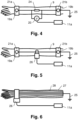
- Fig.4 now shows a variant in which the measuring electrodes 19a, 19b are electrically connected to one another, specifically to a current measuring resistor 24 (case e).
- the fault current is determined via the electrical voltage dropping across the current measuring resistor 24, which is measured with the voltage measuring device 20.
- the voltage measuring device 20 is in turn connected to the wireless transmitter 11a and thus operatively connected to the circuit breaker 3.
- the electrical resistance of the current measuring resistor 24 is lower than that of the human body.
- the fault current then flows at least between the two measuring electrodes 19a, 19b mainly through the current measuring resistor 24 and only to a small extent through the arm of the Person 9.
- the second measuring electrode 19b is directly connected to a ground potential 25, so that no dangerous voltage potentials can arise on the person 9. It is of course also conceivable that a ground electrode 22 is used instead, as in the Fig.3 is shown.
- Fig.5 shows another example for case e), which corresponds to Fig. 2 is very similar to the example shown.
- the two measuring electrodes 19a, 19b are connected directly to an electrical conductor.
- the voltage measuring device 20 is also omitted and instead a through-hole converter 26 is used which measures an electromagnetic field caused by the current flowing between the measuring electrodes 19a, 19b. If the measured fault current exceeds a certain threshold value which represents a danger to the person 9, the circuit from which the danger emanates is again separated from a supply voltage by the circuit breaker 3.
- the connection between the two measuring electrodes 19a, 19b can be designed with a particularly low resistance with this measuring method and hardly any current flows through the arm of the person 9 located in the electrical system 1b.
- Fig.6 now shows an example of an item of clothing 27 which has electrical conductors 28 and which is worn by the person 9 located in the electrical installation 1b (case f).
- the item of clothing 27 is designed as a long glove, but it could also be a combination a short glove with the sleeve of a jacket.
- the item of clothing 27 can be designed, for example, as a glove, jacket, overalls, trousers, shoes or protective suit.
- the electrical conductors 28 are formed by electrically conductive wires running along the arm.
- the wires 28 can be metallic, made of carbon wires or, for example, made of a conductive plastic.
- the wires 28 are incorporated into the item of clothing 27 and preferably do not touch the skin of the person 9 located in the electrical system 1b.
- a layer of cotton fabric or another electrically insulating material lies between the skin and the wires 28.
- the fault current is measured using a through-transducer 26, which is arranged in the area of the wrist, for example, and which in turn measures the electromagnetic field caused by a current flowing through the wires 28 of the item of clothing 27. Because the electrical resistance of the wires 28 is preferably significantly lower than the resistance of the human body, the fault current flows essentially via the wires 28 and only to a very small extent via the arm of the person 9, who is thus particularly well protected from the effects of a fault current. In this example, the wires 28 are in turn connected to a Connected to earth potential 25 so that no dangerous voltage potentials can arise on person 9.
- the Fig.7 shows another example for case f), which corresponds to Fig.6 shown example.
- an electrically conductive braid 29 is incorporated into the item of clothing 27, which in turn can consist of metal, carbon or a conductive plastic.
- the through-hole converter 26 is arranged, for example, in the area of the upper arm, whereby fault currents can also be detected if the person 9 hits conductive parts of the electrical system 1b with his elbow.
- the through-hole converter 26 can also be used in the Fig.7 example shown in the area of the wrist, and the through-hole converter 26 can be arranged in the Fig.6
- the braid 29 advantageously distributes the fault current better to the longitudinal wires.
- an electrically conductive film can be incorporated into the item of clothing 27, which in turn can consist of metal, carbon or a conductive plastic.
- Fig.8 shows a further example for case f), in which the conductive wires 28 are connected to a current measuring resistor 24, which in turn is connected to a ground potential 25.
- the fault current is again determined via the electrical voltage dropping across the current measuring resistor 24, which is measured with the voltage measuring device 20.
- the electrical resistance of the current measuring resistor 24 is also lower than that of the human body, so that the fault current flows mainly through the current measuring resistor 24 and only to a small extent through the arm of the person 9 located in the electrical installation 1b.
- Fig.9 finally shows an example for case f), in which the conductive wires 28 are connected to one another and directly to the ground potential 25.
- An electromagnetic field caused by the current flowing to the ground potential 25 is measured via the through-transformer 26.
- the connection to the ground potential 25 can be made particularly low-resistance with this measuring method, and hardly any current flows through the arm of the person 9 located in the electrical system 1b.
- cases d) to f) can be applied individually or in combination in an electrical system 1b. It is particularly advantageous if cases d) and f) are combined, or cases e) and f).
- the persons 9 in an electrical system 1b should wear protective clothing which, as in case f), is equipped with electrical conductors 28, 29. Contrary to the recommendations or regulations of the operators of the electrical systems 1b, the protective clothing 27 is sometimes not worn, at least for a time. For example, the protective gloves 27 are removed when work has to be carried out which is difficult to do with the protective gloves 27, such as adjustment work or screwing in screws.
- the electrical system 1b can also have several pairs of electrodes 19a, 19b and/or grounding electrodes 22, so that, for example, one person 9 can be equipped with several pairs of electrodes 19a, 19b and/or grounding electrodes 22, or so that several people 9 can be equipped with pairs of electrodes 19a, 19b and/or grounding electrodes 22.
- the electrical system 1b can have one or more of the Figures 4 to 9 illustrated protective equipment for one or more persons 9, in particular protective equipment of different designs.
- the voltage measuring device 20 / current measuring device 26 can be part of the item of clothing 27.
- a through-hole converter 26 can be incorporated into a glove.
- the measurement of the fault current is carried out on the arm of the person 9, in particular on the wrist of the person 9.
- the measurement can also be carried out on another part of the body, for example on the leg or ankle of the person 9.
- the circuit breaker 3 is advantageously not not only switched off/triggered when the person 9 touches conductive parts of the electrical system 1b with their fingers or hand, but also, for example, when they touch them with their hip.
- the fault current is diverted via the legs or feet of the person 9, which can be ensured in particular by connecting the legs or feet to the earth potential 25.
- the entire protective clothing 27 of the person 9 is equipped with electrical conductors 28, 29.
- the technical teaching disclosed for the detection device 5 for detecting the presence of the optical triggering devices 4a, 4b in a danger zone A of the electrical system 1a is also applicable analogously to the voltage measuring device 20 / current measuring device 26 or the transmitter 11a.
- the electrical system 1b can also be designed to detect the presence of the voltage measuring device 20 / current measuring device 26 or the transmitter 11a with the aid of a detection receiver in a danger zone A of the electrical system 1b. Accordingly, triggering or switching off of the circuit breaker 3 by the voltage measuring device 20 / current measuring device 26 is made possible when the voltage measuring device 20 / current measuring device 26 or the transmitter 11a are present in the danger zone A and is otherwise prevented.
- the detection receiver can in turn be formed by the receiver 11b.
- circuit breaker 3 of the Fig.3 can in turn be used as circuit breaker 13, 17a..17b, be designed as an arc short-circuit switch 12a..12b or as a combined line and arc short-circuit switch (see Fig. 2 ).
- the operative connection between the circuit breaker 3 and the voltage measuring device 20 / current measuring device 26 can be established wirelessly or wired.
- the voltage measuring device 20 / current measuring device 26 and the optical triggering devices 4a, 4b can in particular be operatively connected to the same circuit breaker 3.
- one and the same circuit breaker 3 is used to avert the danger of several different faults, namely to prevent an arc L, which can be harmful to the health of the person 9, to prevent a fault current that is harmful to the health of the person 9, and of course also to prevent overcurrents (in the case of a circuit breaker) and also to prevent Arcs L when no person 9 is present (in case of an arc short-circuit switch).
- the optical triggering devices 4a, 4b could also be operatively connected to a different circuit breaker 3 than the voltage measuring device 20 / current measuring device 26. It is also conceivable that the voltage measuring device 20 / current measuring device 26 is operatively connected to a first group of circuit breakers 3 and the optical triggering devices 4a, 4b to a second group of circuit breakers 3. In particular, the two groups can also have an overlap.
Landscapes
- Engineering & Computer Science (AREA)
- Power Engineering (AREA)
- Geophysics And Detection Of Objects (AREA)
- Emergency Protection Circuit Devices (AREA)
- Gas-Insulated Switchgears (AREA)
- Breakers (AREA)
- Keying Circuit Devices (AREA)
Claims (15)
- Installation électrique (1a, 1b), comprenant- une armoire de commande (2, 2a, 2b),- un disjoncteur (3) disposé dans l'armoire de commande (2, 2a, 2b) et- au moins un dispositif de déclenchement optique (4a, 4b) relié fonctionnellement au disjoncteur (3), qui est conçu pour déclencher ou mettre hors tension le disjoncteur (3) lors d'une détection optique d'un arc électrique (L), caractérisée par- un dispositif de détection (5) permettant de détecter l'accès à une zone sécurisée de l'installation électrique (1a, 1b) par détection de la présence de l'au moins un dispositif de déclenchement optique (4a, 4b) dans une zone dangereuse (A) de l'installation électrique (1a, 1b) et- un circuit électronique (6), qui est connecté au dispositif de détection (5) et permet un déclenchement ou respectivement une mise hors tension du disjoncteur (3) par l'au moins un dispositif de déclenchement optique (4a, 4b) lorsque le dispositif de déclenchement optique (4a, 4b) est présent dans la zone dangereuse (A) et est autrement empêché,- dans laquelle une liaison fonctionnelle entre le disjoncteur (3) et le dispositif de déclenchement optique (4a, 4b) est établie sans fil.
- Installation électrique (1a, 1b) selon la revendication 1, caractérisée par le circuit électronique (6) est conçu sous la forme d'une combinaison logique ET d'un signal d'arc électrique positif du dispositif de déclenchement optique (4a, 4b) et d'un signal d'accès du dispositif de détection (5) ou agit comme telle et est relié fonctionnellement côté sortie au disjoncteur (3).
- Installation électrique (1a, 1b) selon la revendication 1 ou 2, caractérisée par- le disjoncteur (3) comporte une entrée de commutation permettant de déclencher ou mettre hors tension le disjoncteur (3),- l'au moins un dispositif de déclenchement optique (4a, 4b) comporte une sortie de commande, qui est reliée à l'entrée de commutation du disjoncteur (3) et- l'au moins un dispositif de déclenchement optique (4a, 4b) est conçu pour modifier l'état de la sortie de commande lors de la détection d'un arc électrique (L) et par conséquent à déclencher ou à mettre hors tension le disjoncteur (3).
- Installation électrique (1a, 1b) selon l'une quelconque des revendications 1 à 3, caractérisée par- un dispositif de mesure de courant de fonctionnement (15b) permettant de mesurer un courant circulant à travers le disjoncteur (3, 13, 17a..17b) ou à travers l'installation électrique (1a, 1b),- un circuit électronique (14), qui est connecté au dispositif de mesure de courant de fonctionnement (15b) et qui permet un déclenchement ou une mise hors tension du disjoncteur (3, 13, 17a..17b) par le dispositif de déclenchement optique (4a, 4b, 15a) uniquement lorsqu'une valeur seuil de courant de fonctionnement est dépassée par le courant de fonctionnement mesuré et/ou une dérivation temporelle du courant de fonctionnement mesuré lorsqu'une valeur seuil de montée est dépassée.
- Installation électrique (1a, 1b) selon l'une quelconque des revendications 1 à 4, caractérisée para) l'au moins un dispositif de déclenchement optique (4a, 4b) est conçu pour être fixé au corps humain oub) l'au moins un dispositif de déclenchement optique (4a, 4b) est disposé dans l'armoire de commande (3) ou à l'extérieur de l'armoire de commande (3) ouc) un premier dispositif de déclenchement optique (4a) est conçu pour être fixé au corps humain et un second dispositif de déclenchement optique (4b) est disposé dans l'armoire de commande (3) ou à l'extérieur de l'armoire de commande (3).
- Installation électrique (1a, 1b) selon l'une quelconque des revendications 1 à 5, caractérisée par- l'installation électrique (1a, 1b) comprend d) deux électrodes de mesure (19a, 19b) comportant un dispositif de mesure de tension (20) disposé entre elles permettant de mesurer la tension entre les électrodes de mesure (19a, 19b) et/ou e) deux électrodes de mesure (19a, 19b) comportant un dispositif de mesure de courant (26) disposé entre elles permettant de mesurer le courant circulant entre les électrodes de mesure (19a, 19b) et/ou f) un revêtement (27) comportant des conducteursélectriques (28, 29) et un dispositif de mesure de courant (26) permettant de mesurer le courant circulant à travers lesdits conducteurs électriques (28),- le dispositif de mesure de tension (20) / le dispositif de mesure de courant (26) est connecté fonctionnellement au disjoncteur (3) et- le dispositif de mesure de tension (20) / le dispositif de mesure de courant (26) est conçu pour déclencher ou mettre hors tension le disjoncteur (3) lors de la détection d'une valeur mesurée supérieure à une valeur seuil.
- Installation électrique (1a, 1b) selon la revendication 6, caractérisée par les électrodes de mesure (19a, 19b) dans les cas d) et e) sont conçues pour être fixées au corps humain.
- Installation électrique (1a, 1b) selon la revendication 7, caractérisée par une électrode (19a, 19b) est respectivement disposée sur un brassard (21a, 21b) respectif / une jambière respective ou que les deux électrodes de mesure (19a, 19b) sont espacées l'une de l'autre sur un seul brassard / une seule jambière.
- Installation électrique (1a, 1b) selon l'une quelconque des revendications 6 à 8, caractérisée par- l'installation électrique (1a, 1b) comporte dans le cas e) une résistance de mesure de courant (24) reliée électriquement aux électrodes de mesure (19a, 19b) et/ou dans le cas f) une résistance de mesure de courant (24) reliée aux conducteurs électriques (28, 29) du revêtement (27), ainsi que, dans les deux cas, un dispositif de mesure de tension (20) permettant de mesurer la tension électrique chutant au de la résistance de mesure de courant (24) et/ou- le dispositif de mesure de courant comporte un convertisseur enfichable (26) permettant de mesurer un champ électromagnétique, qui dans le cas e) est provoqué par un courant circulant entre les électrodes de mesure (19a, 19b) et dans le cas f) par un courant circulant à travers les conducteurs électriques (28, 29) du revêtement (27).
- Installation électrique (1a, 1b) selon l'une quelconque des revendications 6 à 9, caractérisée par les conducteurs électriques disposés dans le revêtement (27) dans le cas f) sont formés par des fils électriquement (28) conducteurs, un tissé électriquement (29) conducteur et/ou par un film électriquement conducteur.
- Installation électrique (1a, 1b) selon l'une quelconque des revendications 6 à 10, caractérisée par l'une des deux électrodes de mesure (19a, 19b) dans les cas d) et e) est reliée à un potentiel de mise à la terre (25) ou une électrode de mise à la terre (22) est connectée à un potentiel de mise à la terre (25), laquelle est conçue pour être fixée au corps humain et/ou dans le cas f) les conducteurs électriques (28, 29) du revêtement (27) sont connectés à un potentiel de mise à la terre (25).
- Installation électrique (1a, 1b) selon l'une quelconque des revendications 6 à 11, caractérisée par une liaison fonctionnelle entre le disjoncteur (3) et le dispositif de mesure de tension (20) / le dispositif de mesure de courant (26) est établie sans fil ou par câble.
- Installation électrique (1a, 1b) selon la revendication 12, caractérisée par le dispositif de détection (5) est conçu sous la forme d'un récepteur de détection sans fil ou est connecté à un récepteur de détection sans fil et est conçu pour détecter le dispositif de déclenchement optique (4a, 4b) comme présent dans une zone dangereuse (A) lorsqu'un signal de transmission provoqué par le dispositif de déclenchement optique (4a, 4b) provoque une intensité de champ de réception dans le récepteur de détection, qui est supérieure à une valeur seuil d'intensité de champ.
- Procédé de sécurisation d'une installation électrique (1a, 1b), qui comprend une armoire de commande (2, 2a, 2b), un disjoncteur (3) disposé dans l'armoire de commande (2, 2a, 2b) et au moins un dispositif de déclenchement optique (4a, 4b) connecté fonctionnellement au disjoncteur (3), qui déclenche ou met hors tension le disjoncteur (3) lors de la détection optique d'un arc électrique (L),
caractérisé en ce que- le disjoncteur (3) est déclenché ou mis hors tension par l'au moins un dispositif de déclenchement optique (4a, 4b) que lorsqu'un accès à une zone sécurisée de l'installation (1a, 1b) électrique est détecté par détection de la présence de l'au moins un dispositif de déclenchement optique (4a, 4b) dans une zone dangereuse (A) de l'installation électrique (1a, 1b), dans lequel une liaison fonctionnelle entre le disjoncteur (3) et le dispositif de déclenchement optique (4a, 4b) est établie sans fil. - Procédé selon la revendication 14, caractérisé par le disjoncteur (3) est déclenché ou mis hors tension par l'au moins un dispositif de déclenchement optique (4a, 4b) que lorsqu'un courant de fonctionnement mesuré à travers le disjoncteur (3) ou à travers l'installation électrique (1a, 1b), dépasse une valeur seuil de courant de fonctionnement et/ou la dérivée temporelle du courant de fonctionnement mesuré dépasse une valeur seuil de montée.
Applications Claiming Priority (2)
| Application Number | Priority Date | Filing Date | Title |
|---|---|---|---|
| DE102016123953.4A DE102016123953A1 (de) | 2016-12-09 | 2016-12-09 | Schaltschrank |
| PCT/EP2017/081245 WO2018104181A1 (fr) | 2016-12-09 | 2017-12-01 | Procédé de coupure d'un arc électrique dans une installation électrique |
Publications (2)
| Publication Number | Publication Date |
|---|---|
| EP3552287A1 EP3552287A1 (fr) | 2019-10-16 |
| EP3552287B1 true EP3552287B1 (fr) | 2024-07-31 |
Family
ID=60543559
Family Applications (1)
| Application Number | Title | Priority Date | Filing Date |
|---|---|---|---|
| EP17808078.4A Active EP3552287B1 (fr) | 2016-12-09 | 2017-12-01 | Procédé de coupure d'un arc électrique dans une installation électrique |
Country Status (6)
| Country | Link |
|---|---|
| US (1) | US11502500B2 (fr) |
| EP (1) | EP3552287B1 (fr) |
| DE (1) | DE102016123953A1 (fr) |
| PL (1) | PL3552287T3 (fr) |
| WO (1) | WO2018104181A1 (fr) |
| ZA (1) | ZA201903668B (fr) |
Families Citing this family (3)
| Publication number | Priority date | Publication date | Assignee | Title |
|---|---|---|---|---|
| GB2585220A (en) * | 2019-07-03 | 2021-01-06 | Eaton Intelligent Power Ltd | Protection system with a switchgear and a slide-in unit and method of inserting the slide-in unit into the switchgear |
| US11862944B1 (en) * | 2022-06-17 | 2024-01-02 | Jst Power Equipment, Inc. | Switchgear device with grounding device and related methods |
| US12444928B2 (en) * | 2023-07-11 | 2025-10-14 | Eaton Intelligent Power Limited | Power system protection device with current limiting and controlled switching functions for AC and DC applications |
Citations (1)
| Publication number | Priority date | Publication date | Assignee | Title |
|---|---|---|---|---|
| DE202012001729U1 (de) * | 2012-02-20 | 2012-04-04 | Dehn + Söhne Gmbh + Co. Kg | Anordnung zum Anlagen- und Personenschutz im Niederspannungsbereich |
Family Cites Families (14)
| Publication number | Priority date | Publication date | Assignee | Title |
|---|---|---|---|---|
| FR2688931B1 (fr) * | 1992-03-19 | 1995-07-07 | Merlin Gerin | Combine de mesure a capteur de courant et transformateur d'alimentation. |
| US5933308A (en) * | 1997-11-19 | 1999-08-03 | Square D Company | Arcing fault protection system for a switchgear enclosure |
| US20050264427A1 (en) * | 2000-03-03 | 2005-12-01 | The Gov. Of The Usa As Repres. By The Secretary Of The Dept. Of Health And Human Services | Electrical injury protection system |
| DE102007022401A1 (de) * | 2007-05-10 | 2008-11-13 | Moeller Gmbh | Leistungsschalter für Störlichtbogenschutz |
| FI20075798A0 (fi) * | 2007-11-12 | 2007-11-12 | Polar Electro Oy | Elektrodirakenne |
| US8351171B2 (en) * | 2008-10-14 | 2013-01-08 | Siemens Industry, Inc. | Integrated automatic selection of maintenance mode in electronic tripping systems to minimize arc fault energy |
| US8649139B2 (en) * | 2010-08-23 | 2014-02-11 | General Electric Company | Methods, systems, and apparatus for detecting arc flash events using current and voltage |
| US8797720B2 (en) * | 2011-09-13 | 2014-08-05 | Utility Relay Company | Manually-controlled arc flash energy reduction system and method for circuit breaker trip units |
| DE102013001612B4 (de) * | 2012-02-20 | 2021-07-01 | Dehn Se + Co Kg | Anordnung zum Anlagen- und Personenschutz |
| US20140043714A1 (en) * | 2012-08-07 | 2014-02-13 | James J. Benke | Switchgear including a circuit breaker having a trip unit with an interface to a number of arc fault sensors |
| US9391441B2 (en) * | 2012-09-12 | 2016-07-12 | Schneider Electric USA, Inc. | Zone selective interlocking for optical flash detection suppression |
| US9270119B2 (en) * | 2013-05-24 | 2016-02-23 | Eaton Corporation | High voltage direct current transmission and distribution system |
| KR101538663B1 (ko) * | 2015-01-30 | 2015-07-23 | (주)에스엔 | 감전을 경보하는 웨어러블 디바이스 및 이와 연동된 수배전반이 포함된 감전 경보 수배전반 시스템 |
| US10832548B2 (en) * | 2018-05-02 | 2020-11-10 | Rockwell Automation Technologies, Inc. | Advanced industrial safety notification systems |
-
2016
- 2016-12-09 DE DE102016123953.4A patent/DE102016123953A1/de not_active Ceased
-
2017
- 2017-12-01 PL PL17808078.4T patent/PL3552287T3/pl unknown
- 2017-12-01 WO PCT/EP2017/081245 patent/WO2018104181A1/fr not_active Ceased
- 2017-12-01 US US16/467,505 patent/US11502500B2/en active Active
- 2017-12-01 EP EP17808078.4A patent/EP3552287B1/fr active Active
-
2019
- 2019-06-07 ZA ZA2019/03668A patent/ZA201903668B/en unknown
Patent Citations (1)
| Publication number | Priority date | Publication date | Assignee | Title |
|---|---|---|---|---|
| DE202012001729U1 (de) * | 2012-02-20 | 2012-04-04 | Dehn + Söhne Gmbh + Co. Kg | Anordnung zum Anlagen- und Personenschutz im Niederspannungsbereich |
Also Published As
| Publication number | Publication date |
|---|---|
| WO2018104181A1 (fr) | 2018-06-14 |
| DE102016123953A1 (de) | 2018-06-14 |
| EP3552287A1 (fr) | 2019-10-16 |
| US20200076181A1 (en) | 2020-03-05 |
| ZA201903668B (en) | 2023-11-29 |
| US11502500B2 (en) | 2022-11-15 |
| PL3552287T3 (pl) | 2024-11-12 |
Similar Documents
| Publication | Publication Date | Title |
|---|---|---|
| EP3551924B1 (fr) | Armoire de commande avec dispositif interrupteur de protection | |
| EP3552287B1 (fr) | Procédé de coupure d'un arc électrique dans une installation électrique | |
| US7292422B2 (en) | Occupancy-based circuit breaker control | |
| EP3189571B1 (fr) | Procédé pour distinguer un arc de lumière d'un gaz lumineux contenant au moins de la vapeur de métal | |
| DE102015218052B4 (de) | Schaltanlage, welche eine Auswerte- und Auslöseelektronik zum Erkennen und Begrenzen der Energie eines Störlichtbogens in einem Einschub eines Schaltschranks der Schaltanlage aufweist | |
| EP3422512B1 (fr) | Commutateur de protection contre l'incendie et procédé | |
| EP3245694B1 (fr) | Procédé de catégorisation d'un arc électrique ou de détection d'un arc électrique parasite | |
| EP2462670B1 (fr) | Configuration d'installation électrique | |
| AT521366B1 (de) | Schutzvorrichtung gegen Stromschläge | |
| EP4367704A1 (fr) | Disjoncteur de protection | |
| EP2143184B1 (fr) | Procédé de déclenchement sélectif d'interrupteurs de puissance | |
| EP0848471A2 (fr) | Dispositif de protection contre les courants de défaut | |
| Dugan | Reducing the flash hazard | |
| Doan et al. | Update of field analysis of arc flash incidents, PPE protective performance and related worker injuries | |
| EP3436835B1 (fr) | Vêtement de protection | |
| EP3300538B1 (fr) | Dispositif permettant d'identifier un arc électrique parasite et installation de distribution électrique | |
| EP3278349A2 (fr) | Ensemble d'armoire électrique avec mise hors circuit améliorée en cas de surcharge | |
| Picard et al. | Practical approaches to mitigating arc flash exposure in Europe | |
| DE761595C (de) | UEberspannungsschutz fuer elektrische Anlagen | |
| WO2017167940A1 (fr) | Système mobile de protection anti-arc électrique | |
| Neitzel | Analyzing electrical hazards in the workplace | |
| EP2495836A1 (fr) | Protection d'installations de mise à la terre dans des stations de transformateurs | |
| Hodder et al. | Practical arc-flash reduction | |
| Irwin et al. | Mitigating personnel exposure to the arc flash hazard | |
| Tyler Klassen | Minimizing arc-flash danger in mining operations |
Legal Events
| Date | Code | Title | Description |
|---|---|---|---|
| STAA | Information on the status of an ep patent application or granted ep patent |
Free format text: STATUS: UNKNOWN |
|
| STAA | Information on the status of an ep patent application or granted ep patent |
Free format text: STATUS: THE INTERNATIONAL PUBLICATION HAS BEEN MADE |
|
| PUAI | Public reference made under article 153(3) epc to a published international application that has entered the european phase |
Free format text: ORIGINAL CODE: 0009012 |
|
| STAA | Information on the status of an ep patent application or granted ep patent |
Free format text: STATUS: REQUEST FOR EXAMINATION WAS MADE |
|
| 17P | Request for examination filed |
Effective date: 20190625 |
|
| AK | Designated contracting states |
Kind code of ref document: A1 Designated state(s): AL AT BE BG CH CY CZ DE DK EE ES FI FR GB GR HR HU IE IS IT LI LT LU LV MC MK MT NL NO PL PT RO RS SE SI SK SM TR |
|
| AX | Request for extension of the european patent |
Extension state: BA ME |
|
| DAV | Request for validation of the european patent (deleted) | ||
| DAX | Request for extension of the european patent (deleted) | ||
| STAA | Information on the status of an ep patent application or granted ep patent |
Free format text: STATUS: EXAMINATION IS IN PROGRESS |
|
| 17Q | First examination report despatched |
Effective date: 20211019 |
|
| P01 | Opt-out of the competence of the unified patent court (upc) registered |
Effective date: 20230521 |
|
| GRAP | Despatch of communication of intention to grant a patent |
Free format text: ORIGINAL CODE: EPIDOSNIGR1 |
|
| STAA | Information on the status of an ep patent application or granted ep patent |
Free format text: STATUS: GRANT OF PATENT IS INTENDED |
|
| GRAS | Grant fee paid |
Free format text: ORIGINAL CODE: EPIDOSNIGR3 |
|
| INTG | Intention to grant announced |
Effective date: 20240528 |
|
| GRAA | (expected) grant |
Free format text: ORIGINAL CODE: 0009210 |
|
| STAA | Information on the status of an ep patent application or granted ep patent |
Free format text: STATUS: THE PATENT HAS BEEN GRANTED |
|
| AK | Designated contracting states |
Kind code of ref document: B1 Designated state(s): AL AT BE BG CH CY CZ DE DK EE ES FI FR GB GR HR HU IE IS IT LI LT LU LV MC MK MT NL NO PL PT RO RS SE SI SK SM TR |
|
| REG | Reference to a national code |
Ref country code: CH Ref legal event code: EP Ref country code: GB Ref legal event code: FG4D Free format text: NOT ENGLISH |
|
| REG | Reference to a national code |
Ref country code: DE Ref legal event code: R096 Ref document number: 502017016313 Country of ref document: DE |
|
| REG | Reference to a national code |
Ref country code: IE Ref legal event code: FG4D Free format text: LANGUAGE OF EP DOCUMENT: GERMAN |
|
| REG | Reference to a national code |
Ref country code: NL Ref legal event code: FP |
|
| REG | Reference to a national code |
Ref country code: SE Ref legal event code: TRGR |
|
| REG | Reference to a national code |
Ref country code: LT Ref legal event code: MG9D |
|
| PG25 | Lapsed in a contracting state [announced via postgrant information from national office to epo] |
Ref country code: PT Free format text: LAPSE BECAUSE OF FAILURE TO SUBMIT A TRANSLATION OF THE DESCRIPTION OR TO PAY THE FEE WITHIN THE PRESCRIBED TIME-LIMIT Effective date: 20241202 |
|
| PG25 | Lapsed in a contracting state [announced via postgrant information from national office to epo] |
Ref country code: PT Free format text: LAPSE BECAUSE OF FAILURE TO SUBMIT A TRANSLATION OF THE DESCRIPTION OR TO PAY THE FEE WITHIN THE PRESCRIBED TIME-LIMIT Effective date: 20241202 |
|
| PG25 | Lapsed in a contracting state [announced via postgrant information from national office to epo] |
Ref country code: NO Free format text: LAPSE BECAUSE OF FAILURE TO SUBMIT A TRANSLATION OF THE DESCRIPTION OR TO PAY THE FEE WITHIN THE PRESCRIBED TIME-LIMIT Effective date: 20241031 |
|
| PG25 | Lapsed in a contracting state [announced via postgrant information from national office to epo] |
Ref country code: GR Free format text: LAPSE BECAUSE OF FAILURE TO SUBMIT A TRANSLATION OF THE DESCRIPTION OR TO PAY THE FEE WITHIN THE PRESCRIBED TIME-LIMIT Effective date: 20241101 Ref country code: FI Free format text: LAPSE BECAUSE OF FAILURE TO SUBMIT A TRANSLATION OF THE DESCRIPTION OR TO PAY THE FEE WITHIN THE PRESCRIBED TIME-LIMIT Effective date: 20240731 |
|
| PG25 | Lapsed in a contracting state [announced via postgrant information from national office to epo] |
Ref country code: BG Free format text: LAPSE BECAUSE OF FAILURE TO SUBMIT A TRANSLATION OF THE DESCRIPTION OR TO PAY THE FEE WITHIN THE PRESCRIBED TIME-LIMIT Effective date: 20240731 |
|
| PG25 | Lapsed in a contracting state [announced via postgrant information from national office to epo] |
Ref country code: LV Free format text: LAPSE BECAUSE OF FAILURE TO SUBMIT A TRANSLATION OF THE DESCRIPTION OR TO PAY THE FEE WITHIN THE PRESCRIBED TIME-LIMIT Effective date: 20240731 |
|
| PG25 | Lapsed in a contracting state [announced via postgrant information from national office to epo] |
Ref country code: IS Free format text: LAPSE BECAUSE OF FAILURE TO SUBMIT A TRANSLATION OF THE DESCRIPTION OR TO PAY THE FEE WITHIN THE PRESCRIBED TIME-LIMIT Effective date: 20241130 |
|
| PG25 | Lapsed in a contracting state [announced via postgrant information from national office to epo] |
Ref country code: HR Free format text: LAPSE BECAUSE OF FAILURE TO SUBMIT A TRANSLATION OF THE DESCRIPTION OR TO PAY THE FEE WITHIN THE PRESCRIBED TIME-LIMIT Effective date: 20240731 |
|
| PG25 | Lapsed in a contracting state [announced via postgrant information from national office to epo] |
Ref country code: ES Free format text: LAPSE BECAUSE OF FAILURE TO SUBMIT A TRANSLATION OF THE DESCRIPTION OR TO PAY THE FEE WITHIN THE PRESCRIBED TIME-LIMIT Effective date: 20240731 Ref country code: RS Free format text: LAPSE BECAUSE OF FAILURE TO SUBMIT A TRANSLATION OF THE DESCRIPTION OR TO PAY THE FEE WITHIN THE PRESCRIBED TIME-LIMIT Effective date: 20241031 |
|
| PG25 | Lapsed in a contracting state [announced via postgrant information from national office to epo] |
Ref country code: RS Free format text: LAPSE BECAUSE OF FAILURE TO SUBMIT A TRANSLATION OF THE DESCRIPTION OR TO PAY THE FEE WITHIN THE PRESCRIBED TIME-LIMIT Effective date: 20241031 Ref country code: NO Free format text: LAPSE BECAUSE OF FAILURE TO SUBMIT A TRANSLATION OF THE DESCRIPTION OR TO PAY THE FEE WITHIN THE PRESCRIBED TIME-LIMIT Effective date: 20241031 Ref country code: LV Free format text: LAPSE BECAUSE OF FAILURE TO SUBMIT A TRANSLATION OF THE DESCRIPTION OR TO PAY THE FEE WITHIN THE PRESCRIBED TIME-LIMIT Effective date: 20240731 Ref country code: IS Free format text: LAPSE BECAUSE OF FAILURE TO SUBMIT A TRANSLATION OF THE DESCRIPTION OR TO PAY THE FEE WITHIN THE PRESCRIBED TIME-LIMIT Effective date: 20241130 Ref country code: HR Free format text: LAPSE BECAUSE OF FAILURE TO SUBMIT A TRANSLATION OF THE DESCRIPTION OR TO PAY THE FEE WITHIN THE PRESCRIBED TIME-LIMIT Effective date: 20240731 Ref country code: GR Free format text: LAPSE BECAUSE OF FAILURE TO SUBMIT A TRANSLATION OF THE DESCRIPTION OR TO PAY THE FEE WITHIN THE PRESCRIBED TIME-LIMIT Effective date: 20241101 Ref country code: FI Free format text: LAPSE BECAUSE OF FAILURE TO SUBMIT A TRANSLATION OF THE DESCRIPTION OR TO PAY THE FEE WITHIN THE PRESCRIBED TIME-LIMIT Effective date: 20240731 Ref country code: ES Free format text: LAPSE BECAUSE OF FAILURE TO SUBMIT A TRANSLATION OF THE DESCRIPTION OR TO PAY THE FEE WITHIN THE PRESCRIBED TIME-LIMIT Effective date: 20240731 Ref country code: BG Free format text: LAPSE BECAUSE OF FAILURE TO SUBMIT A TRANSLATION OF THE DESCRIPTION OR TO PAY THE FEE WITHIN THE PRESCRIBED TIME-LIMIT Effective date: 20240731 |
|
| PG25 | Lapsed in a contracting state [announced via postgrant information from national office to epo] |
Ref country code: SM Free format text: LAPSE BECAUSE OF FAILURE TO SUBMIT A TRANSLATION OF THE DESCRIPTION OR TO PAY THE FEE WITHIN THE PRESCRIBED TIME-LIMIT Effective date: 20240731 Ref country code: RO Free format text: LAPSE BECAUSE OF FAILURE TO SUBMIT A TRANSLATION OF THE DESCRIPTION OR TO PAY THE FEE WITHIN THE PRESCRIBED TIME-LIMIT Effective date: 20240731 Ref country code: DK Free format text: LAPSE BECAUSE OF FAILURE TO SUBMIT A TRANSLATION OF THE DESCRIPTION OR TO PAY THE FEE WITHIN THE PRESCRIBED TIME-LIMIT Effective date: 20240731 |
|
| PG25 | Lapsed in a contracting state [announced via postgrant information from national office to epo] |
Ref country code: EE Free format text: LAPSE BECAUSE OF FAILURE TO SUBMIT A TRANSLATION OF THE DESCRIPTION OR TO PAY THE FEE WITHIN THE PRESCRIBED TIME-LIMIT Effective date: 20240731 |
|
| PG25 | Lapsed in a contracting state [announced via postgrant information from national office to epo] |
Ref country code: CZ Free format text: LAPSE BECAUSE OF FAILURE TO SUBMIT A TRANSLATION OF THE DESCRIPTION OR TO PAY THE FEE WITHIN THE PRESCRIBED TIME-LIMIT Effective date: 20240731 |
|
| PG25 | Lapsed in a contracting state [announced via postgrant information from national office to epo] |
Ref country code: IT Free format text: LAPSE BECAUSE OF FAILURE TO SUBMIT A TRANSLATION OF THE DESCRIPTION OR TO PAY THE FEE WITHIN THE PRESCRIBED TIME-LIMIT Effective date: 20240731 Ref country code: SK Free format text: LAPSE BECAUSE OF FAILURE TO SUBMIT A TRANSLATION OF THE DESCRIPTION OR TO PAY THE FEE WITHIN THE PRESCRIBED TIME-LIMIT Effective date: 20240731 |
|
| REG | Reference to a national code |
Ref country code: DE Ref legal event code: R097 Ref document number: 502017016313 Country of ref document: DE |
|
| PLBE | No opposition filed within time limit |
Free format text: ORIGINAL CODE: 0009261 |
|
| STAA | Information on the status of an ep patent application or granted ep patent |
Free format text: STATUS: NO OPPOSITION FILED WITHIN TIME LIMIT |
|
| PG25 | Lapsed in a contracting state [announced via postgrant information from national office to epo] |
Ref country code: MC Free format text: LAPSE BECAUSE OF FAILURE TO SUBMIT A TRANSLATION OF THE DESCRIPTION OR TO PAY THE FEE WITHIN THE PRESCRIBED TIME-LIMIT Effective date: 20240731 |
|
| 26N | No opposition filed |
Effective date: 20250501 |
|
| REG | Reference to a national code |
Ref country code: CH Ref legal event code: PL |
|
| PG25 | Lapsed in a contracting state [announced via postgrant information from national office to epo] |
Ref country code: LU Free format text: LAPSE BECAUSE OF NON-PAYMENT OF DUE FEES Effective date: 20241201 |
|
| REG | Reference to a national code |
Ref country code: BE Ref legal event code: MM Effective date: 20241231 |
|
| PG25 | Lapsed in a contracting state [announced via postgrant information from national office to epo] |
Ref country code: BE Free format text: LAPSE BECAUSE OF NON-PAYMENT OF DUE FEES Effective date: 20241231 |
|
| PG25 | Lapsed in a contracting state [announced via postgrant information from national office to epo] |
Ref country code: FR Free format text: LAPSE BECAUSE OF NON-PAYMENT OF DUE FEES Effective date: 20241231 |
|
| PG25 | Lapsed in a contracting state [announced via postgrant information from national office to epo] |
Ref country code: CH Free format text: LAPSE BECAUSE OF NON-PAYMENT OF DUE FEES Effective date: 20241231 |
|
| PG25 | Lapsed in a contracting state [announced via postgrant information from national office to epo] |
Ref country code: IE Free format text: LAPSE BECAUSE OF NON-PAYMENT OF DUE FEES Effective date: 20241201 |
|
| PGFP | Annual fee paid to national office [announced via postgrant information from national office to epo] |
Ref country code: NL Payment date: 20251119 Year of fee payment: 9 |
|
| PGFP | Annual fee paid to national office [announced via postgrant information from national office to epo] |
Ref country code: DE Payment date: 20251126 Year of fee payment: 9 |
|
| PGFP | Annual fee paid to national office [announced via postgrant information from national office to epo] |
Ref country code: GB Payment date: 20251119 Year of fee payment: 9 |
|
| PGFP | Annual fee paid to national office [announced via postgrant information from national office to epo] |
Ref country code: SE Payment date: 20251119 Year of fee payment: 9 |
|
| PGFP | Annual fee paid to national office [announced via postgrant information from national office to epo] |
Ref country code: PL Payment date: 20251120 Year of fee payment: 9 |
|
| REG | Reference to a national code |
Ref country code: AT Ref legal event code: MM01 Ref document number: 1709401 Country of ref document: AT Kind code of ref document: T Effective date: 20241201 |
|
| PG25 | Lapsed in a contracting state [announced via postgrant information from national office to epo] |
Ref country code: CY Free format text: LAPSE BECAUSE OF FAILURE TO SUBMIT A TRANSLATION OF THE DESCRIPTION OR TO PAY THE FEE WITHIN THE PRESCRIBED TIME-LIMIT; INVALID AB INITIO Effective date: 20171201 |
|
| PG25 | Lapsed in a contracting state [announced via postgrant information from national office to epo] |
Ref country code: AT Free format text: LAPSE BECAUSE OF NON-PAYMENT OF DUE FEES Effective date: 20241201 |