EP3552296B1 - Procédé d'identification du type d'une tension d'alimentation fournie à un dispositif de commande de moyens d'éclairage - Google Patents
Procédé d'identification du type d'une tension d'alimentation fournie à un dispositif de commande de moyens d'éclairage Download PDFInfo
- Publication number
- EP3552296B1 EP3552296B1 EP17825758.0A EP17825758A EP3552296B1 EP 3552296 B1 EP3552296 B1 EP 3552296B1 EP 17825758 A EP17825758 A EP 17825758A EP 3552296 B1 EP3552296 B1 EP 3552296B1
- Authority
- EP
- European Patent Office
- Prior art keywords
- supply voltage
- voltage
- mains
- operating device
- vref2
- Prior art date
- Legal status (The legal status is an assumption and is not a legal conclusion. Google has not performed a legal analysis and makes no representation as to the accuracy of the status listed.)
- Active
Links
Images


Classifications
-
- H—ELECTRICITY
- H05—ELECTRIC TECHNIQUES NOT OTHERWISE PROVIDED FOR
- H05B—ELECTRIC HEATING; ELECTRIC LIGHT SOURCES NOT OTHERWISE PROVIDED FOR; CIRCUIT ARRANGEMENTS FOR ELECTRIC LIGHT SOURCES, IN GENERAL
- H05B45/00—Circuit arrangements for operating light-emitting diodes [LED]
- H05B45/50—Circuit arrangements for operating light-emitting diodes [LED] responsive to malfunctions or undesirable behaviour of LEDs; responsive to LED life; Protective circuits
-
- H—ELECTRICITY
- H02—GENERATION; CONVERSION OR DISTRIBUTION OF ELECTRIC POWER
- H02J—ELECTRIC POWER NETWORKS; CIRCUIT ARRANGEMENTS OR SYSTEMS FOR SUPPLYING OR DISTRIBUTING ELECTRIC POWER; SYSTEMS FOR STORING ELECTRIC ENERGY
- H02J9/00—Circuit arrangements for emergency or stand-by power supply, e.g. for emergency lighting
- H02J9/04—Circuit arrangements for emergency or stand-by power supply, e.g. for emergency lighting in which the distribution system is disconnected from the normal source and connected to a standby source
Definitions
- the present invention relates to a method with the help of which the type of supply voltage supplied to an operating device for lighting devices can be identified or with the help of which it can be determined whether a sufficient supply voltage is present on the input side of an operating device.
- the present invention further relates to a corresponding circuit arrangement for identifying the type of supplied supply voltage and an operating device for this purpose.
- An emergency lighting unit is shown with an emergency light and a power failure detection circuit, which is designed to analyze the incoming supply voltage.
- a peak value detection of the rectified supply voltage is carried out, with the determined peak value being compared with a reference value. It is also recognized whether the amplitude of the detected supply voltage is sufficient to operate the emergency light.
- an operating device for lighting devices with separate measuring circuits, is proposed in order to break down the voltage rectified by a rectification device into a positive and a negative voltage component, whereby the voltage can be present as an alternating voltage, as a pulsating direct voltage or as a constant direct voltage.
- the operating device also has an evaluation circuit which measures the voltage components of the two Evaluates measuring circuits to identify the type of voltage present.
- the DE 10 2012 206 056 A1 proposes an operating device for lamps, the operating device being connected to a pulsating supply voltage.
- the operating device has detection means for separately detecting the positive voltage component and the negative voltage component of the supply voltage and for generating a measurement signal in which both voltage components are weighted differently.
- the operating device has an evaluation unit for evaluating the measurement signal with the aid of a threshold value transmitter, as well as a control unit which is designed to conclude a logical state based on the evaluation carried out by the evaluation unit, and depending on this logical state, a control signal for control the degree of dimming, the color and/or the color temperature of the connected lamp.
- the present invention is therefore based, on the one hand, on the task of further improving the solutions known from the prior art for identifying the type of supply voltage provided in such a way that a reliable distinction can be made between the different supply voltage types even in the situations described above.
- the object is achieved by a method for identifying the type of supply voltage supplied to an operating device for lighting devices according to claim 1.
- Advantageous developments of the invention are the subject of the dependent claims.
- the task is solved by a circuit arrangement for identifying the type of supply voltage supplied to an operating device for lamps according to claim 9.
- the type of available supply voltage is first determined based on the comparison of the rectified supply voltage with the three reference voltages, and the peak value is compared with the predetermined reference value, the predetermined reference value being dependent on the previously determined type of available supply voltage.
- this third reference voltage is preferably between the first and second reference voltage and is chosen so that it clearly distinguishes between one, even with low loads on the output side AC supply voltage and a quasi-DC supply voltage.
- a method for identifying the type of a supply voltage supplied to an operating device for lighting devices wherein the rectified supply voltage is compared with a first, low reference voltage, a second, high reference voltage and a third reference voltage, which is between the first and the second reference voltage, and a type of available supply voltage is determined depending on the comparison results.
- the circuit arrangement is designed according to the invention to first determine the type of supply voltage available based on the comparison of the rectified supply voltage with the three reference voltages, the peak value being compared with the predetermined reference value, and the predetermined reference value being of the previously determined type depends on the available supply voltage.
- the third reference voltage can be changed. This takes into account the above-mentioned effect that in the case of a low load on the output side, the course of the rectified AC supply voltage approaches the course of the quasi-DC voltage.
- Comparisons of the rectified supply voltage with the three reference voltages can be carried out in different ways. Both a simultaneous comparison can be carried out and it can also be provided that the comparisons are carried out one after the other in time. Particularly in the second variant, the number of components required to identify the type of supply voltage on the input side can be kept low. This means that the technical advantage obtained with the aid of the solution according to the invention can be achieved with relatively little additional effort.
- the peak value of the supplied supply voltage or the rectified supply voltage is also detected, with the presence of a sufficient input-side supply voltage for the circuit arrangement or the operating device only then being determined , when the peak value satisfies a predetermined condition, whereby the peak value exceeds a predetermined reference value.
- Whether or not a predetermined reference voltage is exceeded by the rectified supply voltage is usually carried out using a time measurement. This means that the reference voltage is only detected if this occurs for a certain predetermined period of time, for example 6 ms. However, depending on the frequency of the supply voltage, this means that exceeding a reference voltage for supply voltages of different frequencies different maximum voltages are determined. In order to ensure that the exceeding of a reference value is reliably detected even at higher frequencies of the supply voltages, the reference value must be appropriately adjusted, in particular reduced, which in turn leads to the reference voltages being exceeded at an early stage in the case of supply voltages with low frequencies and thus whether there is sufficient supply voltage is determined.
- the mentioned development according to the invention now provides that an additional criterion is introduced for evaluating the question of whether there is a sufficient supply voltage or not, which is the already mentioned peak value of the supply voltage or the rectified supply voltage. Only if, on the one hand, the presence of a supply voltage is recognized based on a comparison of the rectified supply voltage with the various reference voltages and at the same time the peak value also meets a predetermined condition, the presence of a sufficient supply voltage is recognized, so that it is avoided that when using suitable reference voltages that are for all Frequencies are valid, at low frequencies the operating device is activated prematurely. Ideally, it is provided here that the reference value with which the peak value is compared is dependent on the previously determined type of supply voltage available.
- the reaction of the operating device to the recognized type of supply voltage can then, for example, correspond to the respective country-specific requirements be set. It is particularly preferred here that a user can define the operating modes that are to occur depending on the recognized type of supply voltage, either wired via an interface of the operating device or wirelessly.
- an operating device designated by reference number 10 for operating lamps 50 connected on the output side Shown is an operating device designated by reference number 10 for operating lamps 50 connected on the output side.
- lamps are used in the form of LEDs, but the problem on which the invention is based arises regardless of the exact type of lamp, which is why the invention is not limited to a specific type of lamp.
- they can also be gas discharge lamps, halogen lamps, organic LEDs (OLEDs) or other lighting devices.
- the operating device 10 can, for example be designed in the form of a so-called electronic ballast or a converter.
- the mode of operation of the operating device 10 is to internally convert the supply voltage Vmains present on the input side into an operating voltage suitable for the operation of the lamps 50 and then to output this voltage via the output connections.
- the conversion of the supply voltage Vmains takes place depending on the type of lighting means 50 connected and, if necessary, additional control information in the form of brightness control values, presence, movement information or the like, which can be supplied externally to the operating device 10. Accordingly, inputs for transmitting such control information are in Figure 1 not shown for reasons of clarity.
- Another function of the operating device 10 shown is to enable emergency lighting operation.
- the lamp which contains the operating device 10 and the lamps 50, is integrated into a larger lighting system, with emergency operation of the lamps 50 taking place in the event of an emergency.
- the LEDs 50 are operated permanently with a predetermined brightness in order to enable people in the area illuminated by the lamp to orientate themselves sufficiently safely and, if necessary, to leave this area quickly.
- the lamps 50 are usually operated with a reduced brightness of, for example, 50% compared to the maximum brightness, in order to be able to maintain emergency lighting over a longer period of time in the event of limited energy available.
- the operating device 10 should be able to independently recognize a corresponding emergency state.
- this emergency state is signaled by making a direct voltage available via the power supply lines 1, 2 instead of an alternating voltage supply.
- the operating device 10 recognizes that there is no longer any AC supply voltage on the input side but instead a DC voltage, it will switch to emergency mode and in turn convert the DC supply voltage now provided into a corresponding operating voltage for the lamps 50, so that they are in the Emergency operation described above can be operated.
- Figure 2 A conceivable circuit arrangement is presented, with the help of which the input-side supply voltage Vmains is evaluated.
- the circuit arrangement 20 shown here shows the input-side area of the operating device 10, to a representation of the other components of the operating device 10, which are in particular responsible for the above-mentioned conversion of the supply voltage Vmains into an operating voltage suitable for operating the lamps 50, for reasons of clarity waived.
- the components shown are primarily those that are responsible for evaluating and assessing the input voltage Vmains.
- the voltage Vmains present at the input connections first passes through a noise filter 21, which, as shown, consists of two symmetrical chokes/inductors L1 and L2 and a capacitor C1, which connects the parallel chokes L1, L2 to one another.
- the output of the interference filter 21 is present at the connections A1 and A2 of one diagonal of a bridge rectifier B, which is formed by four bridge diodes D1, D2, D3 and D4.
- One connection A4 of the other diagonal of the bridge rectifier B is connected to ground M, the other connection A3 of the other bridge diagonal carries a voltage which is then further processed by the other components of the operating device, although as mentioned above it is irrelevant in which way this further processing takes place.
- This voltage present at the output connection A3 is also fed to a voltage divider 22, formed from the resistors R1 and R2, the voltage dropping across the lower resistor R2, which represents the measuring resistor, then being evaluated by the evaluation circuit 25.
- the actual evaluation circuit 25 then consists of an interference suppression capacitor C2, but in particular of a comparator K, to which the voltage dropping across the measuring resistor R2 is supplied as the first input signal.
- a second input signal for the comparator K is generated by an arrangement consisting of a unit 26 for generating reference voltages and a multiplexer 27.
- one of the reference voltages is then transmitted to the comparator K as a further input signal via the multiplexer 27.
- the output signal of the comparator K is then evaluated, for example, by a corresponding evaluation circuit 28, which, based on this, recognizes the supply voltage types in the manner described below and, if necessary, adapts the operation of the operating device 10. This procedure for identifying the supply voltage type should be based on the following Figures 3 and 4 be explained in more detail.
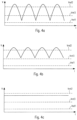
- the Figures 3a to 3c first show the course of the voltage V falling across the measuring resistor R2, which, as already mentioned, represents a first input signal for the comparator K. What is shown here is in particular the voltage curve for a relatively high output load, for example in the event that the lamps 50 are operated at a high brightness.
- the voltage curve is shown here with an AC supply voltage present on the input side
- Figure 3b shows the curve for a quasi-DC supply
- Figure 3c shows the measurement signal in the case of a pure DC supply voltage.
- the multiplexer 27 first provides a low reference voltage as a further input signal for the comparator K, which is the Figures 3a to 3c is labeled Vrefl. As already mentioned, this is a low reference voltage, which primarily serves to detect whether there is any voltage on the input side of the device. Since the operating device 10 has to react very quickly in the event that there is a voltage drop to zero, this comparison is first carried out with the low reference voltage Vrefl in order to ensure that a supply voltage is basically available for the device 10.
- the multiplexer 27 then provides a high reference voltage Vref2 generated by the unit 26, which is also in the Figures 3a to 3c is shown. As can be seen, this is now alternately exceeded or fallen short of in the case of an AC supply voltage or a quasi-DC voltage; in the case of a pure DC supply voltage, however, this second reference voltage Vref2 is either permanently exceeded or - as shown in the example - permanently undercut.
- this third reference voltage Vref3 is selected such that it lies between the two previously described reference voltages Vrefl and Vref2, in such a way that it is regularly undercut or exceeded even with a small output load in the case of an alternating supply voltage, In the case of a quasi-DC supply, however, it is permanently exceeded. This in turn enables a distinction to be made between AC supply voltage and quasi-DC supply voltage, so that ultimately the three different supply voltage types can also be clearly identified in these cases.
- the level of the additionally used third reference voltage Vref3 is variable.
- the level of the third reference voltage is set depending on the dimming value of the lamps 50.
- the dimming value and thus the power at which the lamps 50 are operated influences the load present on the output side of the operating device 10, which in turn influences the course of the measurement signal.
- a third reference voltage value Vrerf3, which takes the dimming value into account, allows an even more precise distinction between the different supply voltage types.
- this embodiment has the advantage that the comparator K can be used in a variety of ways and overall the structure of the components with which the type of supply voltage on the input side can be recognized is kept simpler.
- the presence of a supply voltage or the exceeding of a corresponding reference voltage is only determined if this occurs over a certain period of time, for example 6 ms. This means that only when the reference voltage is permanently exceeded for at least 6 ms is this taken into account by the evaluation unit in order to compensate for any short-term fluctuations.
- the level of the reference voltage would have to be adapted to the frequency of the applied supply voltage. Furthermore, internal deviations in the clock generator of the circuit arrangement could also require a corresponding adjustment of the reference voltage.
- a correspondingly selected reference value which ensures that, for example, at the maximum frequency to be taken into account of 63 Hz, the supply voltage with a peak value of 100 volts can be reliably applied, will, however, lead to lower peak values of the supply voltage at lower frequencies this is interpreted as sufficient supply voltage.
- a lower frequency of 47 Hz of the supply voltage would result in a sufficient supply voltage being determined at a peak value of 70 volts, with this value then increasing continuously until it finally reaches the actually desired peak value of 100 at the maximum frequency of 63 Hz Volt corresponds.
- premature activation of the operating device is undesirable when the supply voltages are too low and, in particular, can lead to serious problems during subsequent operation, a solution must be found to take the frequency-dependent effects described above into account.
- the solution according to the invention consists in creating an additional criterion for actually recognizing that there is a sufficient supply voltage.
- a parameter is used that is already automatically recorded in many operating devices for lighting devices and is therefore available without additional effort.
- This is the peak value of the monitored supply voltage or the rectified supply voltage.
- This peak value is independent of the respective frequency and accordingly offers an additional criterion for determining whether the supply voltage applied to the operating device is actually sufficient.
- Another advantage of the peak value, as already mentioned, is that in many cases it is continuously monitored and recorded anyway, so that no additional effort is required to access this information.
- the so-called state machine is shown schematically here, i.e. the logical procedure of the evaluation unit, which ultimately decides whether there is sufficient supply voltage and accordingly the operating device is started and which mode is selected for later operation.
- a first step S 1 the basic check is carried out as to whether a supply voltage is present, whereby - for example, based on Figures 1 -4 described way - it is determined whether it is an alternating voltage or a direct voltage.
- reference voltage values are then used as described above, which ensure that reliable detection is still possible even in extreme situations, especially in the case of a high frequency of the supply voltage and an unfavorable deviation of the internal clock generator exceeding the reference voltages is detected.
- This information is then output to a subsequent block S2, which then compares the available peak values with reference values in a further step.
- suitable reference values are selected with which the Peak value of the supply voltage is compared. Only if this second test is positive will it be determined that there is sufficient supply voltage on the input side and, accordingly, further operation of the device will be started S3. As already mentioned, the decision can then be made here as to which operating mode the device should be placed in. The assessment of whether the second criterion is also met can in turn be carried out by the evaluation circuit 25 or a corresponding logic that is part of the evaluation circuit 25 or is connected to it.
- the solution according to the invention of additionally taking into account the peak value of the supply voltage ensures that the presence of a sufficient supply voltage is reliably recognized over the entire frequency range, but that the operating device is not activated prematurely, especially at low frequencies.
- the operational reliability of the device is significantly increased with only a small amount of additional effort.
- the presence of a sufficient supply voltage and the type of supply voltage can be reliably recognized, and a suitable operating mode can then be selected depending on the type of supply voltage.
- a user defines the operating modes that are to occur depending on the detected type of supply voltage, either wired via an interface of the operating device 10 or wirelessly.
- the user may be possible for the user to change the operating modes when operating the operating device 10. In this way, it can then be specified, for example, that with a quasi-DC voltage, emergency lighting operation should take place or normal operation should take place.
- the user can, for example, set a specific dimming level to be set depending on the type of supply voltage detected.
- the functionality of the operating device 10 can therefore be extremely flexible to the different Power supply systems and procedures to signal emergency operation must be adapted.
Landscapes
- Business, Economics & Management (AREA)
- Emergency Management (AREA)
- Engineering & Computer Science (AREA)
- Power Engineering (AREA)
- Circuit Arrangement For Electric Light Sources In General (AREA)
Claims (13)
- Procédé pour l'identification de l'application d'une tension d'alimentation (Vmains) suffisante côté entrée à un appareil de fonctionnement (10),une tension d'alimentation (Vmains) fournie à l'appareil de fonctionnement (10) étant redressée et ensuite comparée à trois tensions de référence (Vrefl, Vref2, Vref3),et en outre, pour l'identification de l'application d'une tension d'alimentation (Vmains) suffisante côté entrée, l'application d'une tension d'alimentation (Vmains) côté entrée n'étant constatée que lorsqu'au cours d'une mesure temporelle, la tension d'alimentation redressée est supérieure à au moins l'une des trois tensions de référence (Vrefl, Vref2, Vref3) pendant une période de temps spécifiée,caractérisé en ce que,en plus, la valeur de crête de la tension d'alimentation (Vmains) fournie ou de la tension d'alimentation redressée est également détectée eten ce que l'application d'une tension d'alimentation (Vmains) suffisante côté entrée n'est constatée que lorsquei. à l'aide de la comparaison de la tension d'alimentation redressée aux trois tensions de référence (Vrefl, Vref2, Vref3), l'application d'une tension d'alimentation est constatée ; etii. la valeur de crête répond à une condition spécifiée, la valeur de crête étant supérieure à une valeur de référence spécifiée ;le type de la tension d'alimentation (Vmains) à disposition étant d'abord déterminé à l'aide de la comparaison de la tension d'alimentation redressée aux trois tensions de référence (Vrefl, Vref2, Vref3) eten ce que la valeur de crête est comparée à la valeur de référence spécifiée, la valeur de référence spécifiée dépendant du type, prédéterminé, de tension d'alimentation (Vmains) à disposition.
- Procédé selon la revendication 1,la tension d'alimentation redressée étant comparée à une première tension de référence basse (Vref1), à une deuxième tension de référence élevée (Vref2) ainsi qu'à une troisième tension de référence (Vref3) qui est située entre la première et la deuxième tension de référence (Vrefl, Vref2),et en ce qu'en fonction des résultats de comparaison, un type de tension d'alimentation (Vmains) à disposition étant déterminé.
- Procédé selon la revendication 2,
le niveau de la troisième tension de référence (Vref3) étant modifiable. - Procédé selon la revendication 2 ou 3,
les comparaisons de la tension d'alimentation redressée aux trois tensions de référence (Vrefl, Vref2, Vref3) étant effectuées successivement dans le temps. - Procédé selon l'une des revendications 2 à 4,le type de tension d'alimentation (Vmains) à disposition étant identifié de manière tellequ'une tension d'alimentation de CA est détectée lorsque la deuxième et la troisième tension de référence (Vref2, Vref3) sont dépassées en alternance, tant vers le haut que vers le bas,qu'une tension d'alimentation de CC est détectée lorsque la troisième tension de référence (Vref3) est dépassée durablement vers le haut et la deuxième tension de référence (Vref2) est dépassée durablement vers le haut ou vers le bas,et qu'une tension d'alimentation de quasi-CC est détectée lorsque la troisième tension de référence (Vref3) est dépassée durablement vers le haut et la deuxième tension de référence (Vref2) est dépassée en alternance vers le haut et vers le bas.
- Procédé selon la revendication 5,
un mode de fonctionnement pour l'appareil de fonctionnement (10), pour le fonctionnement des moyens d'éclairage (50), étant choisi en fonction du type déterminé de tension d'alimentation (Vmains) à disposition. - Procédé selon la revendication 6,
un fonctionnement de secours étant choisi dans le cas d'au moins un type de tension d'alimentation (Vmains) à disposition, en particulier dans le cas d'une tension d'alimentation de CC ou d'une tension d'alimentation de quasi-CC. - Procédé selon la revendication 6 ou 7,
des modes de fonctionnement pour l'appareil de fonctionnement (10) étant définis par un utilisateur par l'intermédiaire d'une interface câblée de l'appareil de fonctionnement (10) ou par l'intermédiaire de moyens pour une communication sans fil de l'appareil de fonctionnement (10), lesquels modes de fonctionnement devant se produire en fonction du type déterminé de tension d'alimentation (Vmains) à disposition. - Ensemble de circuits pour l'identification de l'application d'une tension d'alimentation (Vmains) suffisante côté entrée à un appareil de fonctionnement (10) de moyens d'éclairage (50),l'ensemble de circuits (20) présentant des moyens pour le redressement (B) de la tension d'alimentation (Vmains) fournie à l'appareil de fonctionnement (10) ainsi que pour la comparaison consécutive à trois tensions de référence (Vrefl, Vref2, Vref3),et en outre une unité d'évaluation (28) étant prévue, qui, pour l'identification de l'application d'une tension d'alimentation (Vmains) suffisante côté entrée, ne constate l'application d'une tension d'alimentation (Vmains) côté entrée que lorsque la tension d'alimentation redressée est supérieure à au moins l'une des trois tensions de référence (Vrefl, Vref2, Vref3) pendant une période de temps spécifiée,caractérisé en ce quel'ensemble de circuits est conçu pour détecter, en plus, la valeur de crête de la tension d'alimentation (Vmains) fournie ou de la tension d'alimentation redressée eten ce que l'application d'une tension d'alimentation (Vmains) suffisante côté entrée n'est constatée que lorsquei. à l'aide de la comparaison de la tension d'alimentation redressée aux trois tensions de référence (Vrefl, Vref2, Vref3), l'application d'une tension d'alimentation est constatée ; etii. la valeur de crête répond à une condition spécifiée, la valeur de crête étant supérieure à une valeur de référence spécifiée ;l'ensemble de circuits étant conçu pour déterminer d'abord, à l'aide de la comparaison de la tension d'alimentation redressée aux trois tensions de référence (Vrefl, Vref2 et Vref3), le type de la tension d'alimentation (Vmains) à disposition eten ce que la valeur de crête est comparée à la valeur de référence spécifiée, la valeur de référence spécifiée dépendant du type, prédéterminé, de tension d'alimentation (Vmains) à disposition.
- Ensemble de circuits selon la revendication 9,
l'ensemble de circuits étant conçu pour :a) comparer la tension d'alimentation redressée à une première tension de référence basse (Vref1), à une deuxième tension de référence élevée (Vref2) ainsi qu'à une troisième tension de référence (Vref3) qui est située entre la première et la deuxième tension de référence (Vrefl, Vref2), etb) déterminer, en fonction des résultats de comparaison, un type de tension d'alimentation (Vmains) à disposition. - Appareil de fonctionnement (10) pour le fonctionnement des moyens d'éclairage (50), présentant un ensemble de circuits selon l'une des revendications 9 ou 10.
- Appareil de fonctionnement selon la revendication 11,
l'appareil de fonctionnement (10) étant conçu pour faire fonctionner les moyens d'éclairage (50) dans un fonctionnement de secours lors de la détermination d'un type spécifié de tension d'alimentation (Vmains) à disposition, en particulier dans le cas d'une tension d'alimentation de CC ou d'une tension d'alimentation de quasi-CC. - Appareil de fonctionnement selon la revendication 12,
celui-ci présentant une interface câblée ou des moyens pour une communication sans fil par l'intermédiaire de laquelle/desquels des modes de fonctionnement pour l'appareil de fonctionnement (10) peuvent être définis, qui doivent se produire en fonction du type déterminé de tension d'alimentation (Vmains) à disposition.
Applications Claiming Priority (3)
| Application Number | Priority Date | Filing Date | Title |
|---|---|---|---|
| DE102016224349.7A DE102016224349A1 (de) | 2016-12-07 | 2016-12-07 | Verfahren zum Identifizieren des Typs einer einem Betriebsgerät für Leuchtmittel zugeführten Versorgungsspannung |
| ATGM232/2017U AT17444U1 (de) | 2016-12-07 | 2017-10-23 | Verfahren zum Identifizieren des Typs einer einem Betriebsgerät für Leuchtmittel zugeführten Versorgungsspannung |
| PCT/EP2017/081527 WO2018104302A1 (fr) | 2016-12-07 | 2017-12-05 | Procédé d'identification du type d'une tension d'alimentation fournie à un dispositif de commande de moyens d'éclairage |
Publications (2)
| Publication Number | Publication Date |
|---|---|
| EP3552296A1 EP3552296A1 (fr) | 2019-10-16 |
| EP3552296B1 true EP3552296B1 (fr) | 2023-11-01 |
Family
ID=60937681
Family Applications (1)
| Application Number | Title | Priority Date | Filing Date |
|---|---|---|---|
| EP17825758.0A Active EP3552296B1 (fr) | 2016-12-07 | 2017-12-05 | Procédé d'identification du type d'une tension d'alimentation fournie à un dispositif de commande de moyens d'éclairage |
Country Status (1)
| Country | Link |
|---|---|
| EP (1) | EP3552296B1 (fr) |
Citations (2)
| Publication number | Priority date | Publication date | Assignee | Title |
|---|---|---|---|---|
| DE102012206056A1 (de) * | 2012-04-13 | 2013-10-17 | Tridonic Gmbh & Co. Kg | Ansteuerung von Leuchtmitteln mittels definierter Manipulation der Versorgungsspannung |
| CN105633911A (zh) * | 2015-12-30 | 2016-06-01 | 生迪智慧科技有限公司 | Led装置的保护电路及方法 |
-
2017
- 2017-12-05 EP EP17825758.0A patent/EP3552296B1/fr active Active
Patent Citations (3)
| Publication number | Priority date | Publication date | Assignee | Title |
|---|---|---|---|---|
| DE102012206056A1 (de) * | 2012-04-13 | 2013-10-17 | Tridonic Gmbh & Co. Kg | Ansteuerung von Leuchtmitteln mittels definierter Manipulation der Versorgungsspannung |
| CN105633911A (zh) * | 2015-12-30 | 2016-06-01 | 生迪智慧科技有限公司 | Led装置的保护电路及方法 |
| WO2017114114A1 (fr) * | 2015-12-30 | 2017-07-06 | Sengled Co., Ltd. | Circuit de protection de dispositif à del et procédé correspondant |
Also Published As
| Publication number | Publication date |
|---|---|
| EP3552296A1 (fr) | 2019-10-16 |
Similar Documents
| Publication | Publication Date | Title |
|---|---|---|
| DE102007040555B4 (de) | Verfahren und Schaltung zum Identifizieren der Art einer Spannung, insbesondere der einem Betriebsgerät für Notlichtleuchten zugeführten Betriebsspannung | |
| EP2292079B1 (fr) | Identification du type d'une ampoule au moyen d'un circuit de correction de facteur de puissance | |
| EP3183584B1 (fr) | Dispositif de détection d'une tension d'alimentation et procédé de détection d'une tension d'alimentation | |
| DE102010048980A1 (de) | Steuervorrichtung und Verfahren zur Detektion einer Lastart | |
| DE19757295B4 (de) | Elektronisches Vorschaltgerät | |
| DE10163034B4 (de) | Elektronisches Vorschaltgerät mit Überspannungsüberwachung | |
| DE102017127070A1 (de) | Schaltungsanordnung und Verfahren zur Überwachung wechselspannungsförmiger Signale | |
| EP2656696B1 (fr) | Analyse de la tension d'alimentation des ballasts de luminaires | |
| EP0525345B2 (fr) | Dispositif et procédé de surveillance d'une flamme | |
| EP3552296B1 (fr) | Procédé d'identification du type d'une tension d'alimentation fournie à un dispositif de commande de moyens d'éclairage | |
| DE102012206056A1 (de) | Ansteuerung von Leuchtmitteln mittels definierter Manipulation der Versorgungsspannung | |
| EP2368410B1 (fr) | Procédé et ballast pour le fonctionnement d'un moyen d'éclairage avec un courant régulé | |
| EP2130412B1 (fr) | Détection de défaut dans un appareil électrique pour moyen d'éclairage | |
| WO2018104302A1 (fr) | Procédé d'identification du type d'une tension d'alimentation fournie à un dispositif de commande de moyens d'éclairage | |
| WO2012062664A1 (fr) | Commande d'un luminaire protégée contre les perturbations | |
| AT17444U1 (de) | Verfahren zum Identifizieren des Typs einer einem Betriebsgerät für Leuchtmittel zugeführten Versorgungsspannung | |
| DE69406796T2 (de) | Mikroprozessoreinrichtung zur überwachung von beleuchtungselementen und verfahren mit solch einer einrichtung | |
| EP4587286A1 (fr) | Détection d'erreur d'isolation basée sur des composantes de tension alternative d'un signal d'activation dans le côté tension continue d'un circuit de charge à tension alternative | |
| DE102013201588B4 (de) | Verfahren zur Übermittlung von Datensignalen, Leuchte, Versorgungsgerät und System zur Beleuchtung | |
| DE102018127452B3 (de) | Verfahren zum Betrieb einer Dimmer-Leuchtmittel-Kombination sowie Dimmer für eine Dimmer-Leuchtmittel-Kombination | |
| EP3235341B1 (fr) | Unité de commande ayant des moyens de détection pour détecter des entrées et/ou sorties de phase dans la tension d'alimentation | |
| EP3603345A1 (fr) | Ensemble de circuits et procédé pour faire fonctionner des moyens d'éclairage | |
| DE102012112641B4 (de) | Vorrichtung und Verfahren zur Erkennung einer durch eine elektronische Steuerschaltung ansteuerbaren Lastart in einer Beleuchtungsinstallation | |
| DE102014102843A1 (de) | Eingangsspannung erkennendes Betriebsgerät für Leuchtmittel | |
| DE10163033A1 (de) | Elektronisches Vorschaltgerät mit Überwachungsschaltung zum Erkennen des in einer Gasentladungslampe auftretenden Gleichrichteffekts |
Legal Events
| Date | Code | Title | Description |
|---|---|---|---|
| STAA | Information on the status of an ep patent application or granted ep patent |
Free format text: STATUS: UNKNOWN |
|
| STAA | Information on the status of an ep patent application or granted ep patent |
Free format text: STATUS: THE INTERNATIONAL PUBLICATION HAS BEEN MADE |
|
| PUAI | Public reference made under article 153(3) epc to a published international application that has entered the european phase |
Free format text: ORIGINAL CODE: 0009012 |
|
| STAA | Information on the status of an ep patent application or granted ep patent |
Free format text: STATUS: REQUEST FOR EXAMINATION WAS MADE |
|
| 17P | Request for examination filed |
Effective date: 20190607 |
|
| AK | Designated contracting states |
Kind code of ref document: A1 Designated state(s): AL AT BE BG CH CY CZ DE DK EE ES FI FR GB GR HR HU IE IS IT LI LT LU LV MC MK MT NL NO PL PT RO RS SE SI SK SM TR |
|
| AX | Request for extension of the european patent |
Extension state: BA ME |
|
| DAV | Request for validation of the european patent (deleted) | ||
| DAX | Request for extension of the european patent (deleted) | ||
| STAA | Information on the status of an ep patent application or granted ep patent |
Free format text: STATUS: EXAMINATION IS IN PROGRESS |
|
| 17Q | First examination report despatched |
Effective date: 20211215 |
|
| REG | Reference to a national code |
Ref country code: DE Ref legal event code: R079 Ipc: H05B0045500000 Ref country code: DE Ref legal event code: R079 Ref document number: 502017015565 Country of ref document: DE Free format text: PREVIOUS MAIN CLASS: H02J0009040000 Ipc: H05B0045500000 |
|
| GRAP | Despatch of communication of intention to grant a patent |
Free format text: ORIGINAL CODE: EPIDOSNIGR1 |
|
| STAA | Information on the status of an ep patent application or granted ep patent |
Free format text: STATUS: GRANT OF PATENT IS INTENDED |
|
| RIC1 | Information provided on ipc code assigned before grant |
Ipc: H05B 45/50 20220101AFI20230626BHEP |
|
| INTG | Intention to grant announced |
Effective date: 20230718 |
|
| GRAS | Grant fee paid |
Free format text: ORIGINAL CODE: EPIDOSNIGR3 |
|
| GRAA | (expected) grant |
Free format text: ORIGINAL CODE: 0009210 |
|
| STAA | Information on the status of an ep patent application or granted ep patent |
Free format text: STATUS: THE PATENT HAS BEEN GRANTED |
|
| AK | Designated contracting states |
Kind code of ref document: B1 Designated state(s): AL AT BE BG CH CY CZ DE DK EE ES FI FR GB GR HR HU IE IS IT LI LT LU LV MC MK MT NL NO PL PT RO RS SE SI SK SM TR |
|
| REG | Reference to a national code |
Ref country code: GB Ref legal event code: FG4D Free format text: NOT ENGLISH |
|
| REG | Reference to a national code |
Ref country code: CH Ref legal event code: EP |
|
| REG | Reference to a national code |
Ref country code: DE Ref legal event code: R096 Ref document number: 502017015565 Country of ref document: DE |
|
| REG | Reference to a national code |
Ref country code: IE Ref legal event code: FG4D Free format text: LANGUAGE OF EP DOCUMENT: GERMAN |
|
| REG | Reference to a national code |
Ref country code: DE Ref legal event code: R084 Ref document number: 502017015565 Country of ref document: DE |
|
| P01 | Opt-out of the competence of the unified patent court (upc) registered |
Effective date: 20231130 |
|
| REG | Reference to a national code |
Ref country code: LT Ref legal event code: MG9D |
|
| REG | Reference to a national code |
Ref country code: NL Ref legal event code: MP Effective date: 20231101 |
|
| PG25 | Lapsed in a contracting state [announced via postgrant information from national office to epo] |
Ref country code: IS Free format text: LAPSE BECAUSE OF FAILURE TO SUBMIT A TRANSLATION OF THE DESCRIPTION OR TO PAY THE FEE WITHIN THE PRESCRIBED TIME-LIMIT Effective date: 20240301 |
|
| PG25 | Lapsed in a contracting state [announced via postgrant information from national office to epo] |
Ref country code: LT Free format text: LAPSE BECAUSE OF FAILURE TO SUBMIT A TRANSLATION OF THE DESCRIPTION OR TO PAY THE FEE WITHIN THE PRESCRIBED TIME-LIMIT Effective date: 20231101 |
|
| PG25 | Lapsed in a contracting state [announced via postgrant information from national office to epo] |
Ref country code: NL Free format text: LAPSE BECAUSE OF FAILURE TO SUBMIT A TRANSLATION OF THE DESCRIPTION OR TO PAY THE FEE WITHIN THE PRESCRIBED TIME-LIMIT Effective date: 20231101 |
|
| PG25 | Lapsed in a contracting state [announced via postgrant information from national office to epo] |
Ref country code: ES Free format text: LAPSE BECAUSE OF FAILURE TO SUBMIT A TRANSLATION OF THE DESCRIPTION OR TO PAY THE FEE WITHIN THE PRESCRIBED TIME-LIMIT Effective date: 20231101 |
|
| PG25 | Lapsed in a contracting state [announced via postgrant information from national office to epo] |
Ref country code: NL Free format text: LAPSE BECAUSE OF FAILURE TO SUBMIT A TRANSLATION OF THE DESCRIPTION OR TO PAY THE FEE WITHIN THE PRESCRIBED TIME-LIMIT Effective date: 20231101 Ref country code: LT Free format text: LAPSE BECAUSE OF FAILURE TO SUBMIT A TRANSLATION OF THE DESCRIPTION OR TO PAY THE FEE WITHIN THE PRESCRIBED TIME-LIMIT Effective date: 20231101 Ref country code: IS Free format text: LAPSE BECAUSE OF FAILURE TO SUBMIT A TRANSLATION OF THE DESCRIPTION OR TO PAY THE FEE WITHIN THE PRESCRIBED TIME-LIMIT Effective date: 20240301 Ref country code: ES Free format text: LAPSE BECAUSE OF FAILURE TO SUBMIT A TRANSLATION OF THE DESCRIPTION OR TO PAY THE FEE WITHIN THE PRESCRIBED TIME-LIMIT Effective date: 20231101 Ref country code: BG Free format text: LAPSE BECAUSE OF FAILURE TO SUBMIT A TRANSLATION OF THE DESCRIPTION OR TO PAY THE FEE WITHIN THE PRESCRIBED TIME-LIMIT Effective date: 20240201 Ref country code: PT Free format text: LAPSE BECAUSE OF FAILURE TO SUBMIT A TRANSLATION OF THE DESCRIPTION OR TO PAY THE FEE WITHIN THE PRESCRIBED TIME-LIMIT Effective date: 20240301 |
|
| PG25 | Lapsed in a contracting state [announced via postgrant information from national office to epo] |
Ref country code: SE Free format text: LAPSE BECAUSE OF FAILURE TO SUBMIT A TRANSLATION OF THE DESCRIPTION OR TO PAY THE FEE WITHIN THE PRESCRIBED TIME-LIMIT Effective date: 20231101 Ref country code: RS Free format text: LAPSE BECAUSE OF FAILURE TO SUBMIT A TRANSLATION OF THE DESCRIPTION OR TO PAY THE FEE WITHIN THE PRESCRIBED TIME-LIMIT Effective date: 20231101 Ref country code: PL Free format text: LAPSE BECAUSE OF FAILURE TO SUBMIT A TRANSLATION OF THE DESCRIPTION OR TO PAY THE FEE WITHIN THE PRESCRIBED TIME-LIMIT Effective date: 20231101 Ref country code: NO Free format text: LAPSE BECAUSE OF FAILURE TO SUBMIT A TRANSLATION OF THE DESCRIPTION OR TO PAY THE FEE WITHIN THE PRESCRIBED TIME-LIMIT Effective date: 20240201 Ref country code: LV Free format text: LAPSE BECAUSE OF FAILURE TO SUBMIT A TRANSLATION OF THE DESCRIPTION OR TO PAY THE FEE WITHIN THE PRESCRIBED TIME-LIMIT Effective date: 20231101 Ref country code: HR Free format text: LAPSE BECAUSE OF FAILURE TO SUBMIT A TRANSLATION OF THE DESCRIPTION OR TO PAY THE FEE WITHIN THE PRESCRIBED TIME-LIMIT Effective date: 20231101 |
|
| PG25 | Lapsed in a contracting state [announced via postgrant information from national office to epo] |
Ref country code: DK Free format text: LAPSE BECAUSE OF FAILURE TO SUBMIT A TRANSLATION OF THE DESCRIPTION OR TO PAY THE FEE WITHIN THE PRESCRIBED TIME-LIMIT Effective date: 20231101 |
|
| PG25 | Lapsed in a contracting state [announced via postgrant information from national office to epo] |
Ref country code: CZ Free format text: LAPSE BECAUSE OF FAILURE TO SUBMIT A TRANSLATION OF THE DESCRIPTION OR TO PAY THE FEE WITHIN THE PRESCRIBED TIME-LIMIT Effective date: 20231101 |
|
| PG25 | Lapsed in a contracting state [announced via postgrant information from national office to epo] |
Ref country code: SK Free format text: LAPSE BECAUSE OF FAILURE TO SUBMIT A TRANSLATION OF THE DESCRIPTION OR TO PAY THE FEE WITHIN THE PRESCRIBED TIME-LIMIT Effective date: 20231101 |
|
| PG25 | Lapsed in a contracting state [announced via postgrant information from national office to epo] |
Ref country code: SM Free format text: LAPSE BECAUSE OF FAILURE TO SUBMIT A TRANSLATION OF THE DESCRIPTION OR TO PAY THE FEE WITHIN THE PRESCRIBED TIME-LIMIT Effective date: 20231101 Ref country code: SK Free format text: LAPSE BECAUSE OF FAILURE TO SUBMIT A TRANSLATION OF THE DESCRIPTION OR TO PAY THE FEE WITHIN THE PRESCRIBED TIME-LIMIT Effective date: 20231101 Ref country code: IT Free format text: LAPSE BECAUSE OF FAILURE TO SUBMIT A TRANSLATION OF THE DESCRIPTION OR TO PAY THE FEE WITHIN THE PRESCRIBED TIME-LIMIT Effective date: 20231101 Ref country code: EE Free format text: LAPSE BECAUSE OF FAILURE TO SUBMIT A TRANSLATION OF THE DESCRIPTION OR TO PAY THE FEE WITHIN THE PRESCRIBED TIME-LIMIT Effective date: 20231101 Ref country code: DK Free format text: LAPSE BECAUSE OF FAILURE TO SUBMIT A TRANSLATION OF THE DESCRIPTION OR TO PAY THE FEE WITHIN THE PRESCRIBED TIME-LIMIT Effective date: 20231101 Ref country code: CZ Free format text: LAPSE BECAUSE OF FAILURE TO SUBMIT A TRANSLATION OF THE DESCRIPTION OR TO PAY THE FEE WITHIN THE PRESCRIBED TIME-LIMIT Effective date: 20231101 |
|
| REG | Reference to a national code |
Ref country code: DE Ref legal event code: R097 Ref document number: 502017015565 Country of ref document: DE |
|
| PG25 | Lapsed in a contracting state [announced via postgrant information from national office to epo] |
Ref country code: LU Free format text: LAPSE BECAUSE OF NON-PAYMENT OF DUE FEES Effective date: 20231205 |
|
| PG25 | Lapsed in a contracting state [announced via postgrant information from national office to epo] |
Ref country code: MC Free format text: LAPSE BECAUSE OF FAILURE TO SUBMIT A TRANSLATION OF THE DESCRIPTION OR TO PAY THE FEE WITHIN THE PRESCRIBED TIME-LIMIT Effective date: 20231101 |
|
| REG | Reference to a national code |
Ref country code: BE Ref legal event code: MM Effective date: 20231231 |
|
| PG25 | Lapsed in a contracting state [announced via postgrant information from national office to epo] |
Ref country code: MC Free format text: LAPSE BECAUSE OF FAILURE TO SUBMIT A TRANSLATION OF THE DESCRIPTION OR TO PAY THE FEE WITHIN THE PRESCRIBED TIME-LIMIT Effective date: 20231101 Ref country code: LU Free format text: LAPSE BECAUSE OF NON-PAYMENT OF DUE FEES Effective date: 20231205 |
|
| PLBE | No opposition filed within time limit |
Free format text: ORIGINAL CODE: 0009261 |
|
| STAA | Information on the status of an ep patent application or granted ep patent |
Free format text: STATUS: NO OPPOSITION FILED WITHIN TIME LIMIT |
|
| 26N | No opposition filed |
Effective date: 20240802 |
|
| REG | Reference to a national code |
Ref country code: IE Ref legal event code: MM4A |
|
| PG25 | Lapsed in a contracting state [announced via postgrant information from national office to epo] |
Ref country code: IE Free format text: LAPSE BECAUSE OF NON-PAYMENT OF DUE FEES Effective date: 20231205 |
|
| PG25 | Lapsed in a contracting state [announced via postgrant information from national office to epo] |
Ref country code: BE Free format text: LAPSE BECAUSE OF NON-PAYMENT OF DUE FEES Effective date: 20231231 |
|
| PG25 | Lapsed in a contracting state [announced via postgrant information from national office to epo] |
Ref country code: SI Free format text: LAPSE BECAUSE OF FAILURE TO SUBMIT A TRANSLATION OF THE DESCRIPTION OR TO PAY THE FEE WITHIN THE PRESCRIBED TIME-LIMIT Effective date: 20231101 |
|
| PG25 | Lapsed in a contracting state [announced via postgrant information from national office to epo] |
Ref country code: SI Free format text: LAPSE BECAUSE OF FAILURE TO SUBMIT A TRANSLATION OF THE DESCRIPTION OR TO PAY THE FEE WITHIN THE PRESCRIBED TIME-LIMIT Effective date: 20231101 Ref country code: IE Free format text: LAPSE BECAUSE OF NON-PAYMENT OF DUE FEES Effective date: 20231205 Ref country code: BE Free format text: LAPSE BECAUSE OF NON-PAYMENT OF DUE FEES Effective date: 20231231 |
|
| PGFP | Annual fee paid to national office [announced via postgrant information from national office to epo] |
Ref country code: FR Payment date: 20241227 Year of fee payment: 8 |
|
| REG | Reference to a national code |
Ref country code: AT Ref legal event code: MM01 Ref document number: 1628730 Country of ref document: AT Kind code of ref document: T Effective date: 20231205 |
|
| PG25 | Lapsed in a contracting state [announced via postgrant information from national office to epo] |
Ref country code: AT Free format text: LAPSE BECAUSE OF NON-PAYMENT OF DUE FEES Effective date: 20231205 |
|
| PGFP | Annual fee paid to national office [announced via postgrant information from national office to epo] |
Ref country code: CH Payment date: 20250101 Year of fee payment: 8 |
|
| PG25 | Lapsed in a contracting state [announced via postgrant information from national office to epo] |
Ref country code: RO Free format text: LAPSE BECAUSE OF FAILURE TO SUBMIT A TRANSLATION OF THE DESCRIPTION OR TO PAY THE FEE WITHIN THE PRESCRIBED TIME-LIMIT Effective date: 20231101 |
|
| PG25 | Lapsed in a contracting state [announced via postgrant information from national office to epo] |
Ref country code: FI Free format text: LAPSE BECAUSE OF FAILURE TO SUBMIT A TRANSLATION OF THE DESCRIPTION OR TO PAY THE FEE WITHIN THE PRESCRIBED TIME-LIMIT Effective date: 20231101 |
|
| PG25 | Lapsed in a contracting state [announced via postgrant information from national office to epo] |
Ref country code: CY Free format text: LAPSE BECAUSE OF FAILURE TO SUBMIT A TRANSLATION OF THE DESCRIPTION OR TO PAY THE FEE WITHIN THE PRESCRIBED TIME-LIMIT; INVALID AB INITIO Effective date: 20171205 |
|
| PG25 | Lapsed in a contracting state [announced via postgrant information from national office to epo] |
Ref country code: HU Free format text: LAPSE BECAUSE OF FAILURE TO SUBMIT A TRANSLATION OF THE DESCRIPTION OR TO PAY THE FEE WITHIN THE PRESCRIBED TIME-LIMIT; INVALID AB INITIO Effective date: 20171205 |
|
| PG25 | Lapsed in a contracting state [announced via postgrant information from national office to epo] |
Ref country code: GR Free format text: LAPSE BECAUSE OF FAILURE TO SUBMIT A TRANSLATION OF THE DESCRIPTION OR TO PAY THE FEE WITHIN THE PRESCRIBED TIME-LIMIT; INVALID AB INITIO Effective date: 20171205 |
|
| PG25 | Lapsed in a contracting state [announced via postgrant information from national office to epo] |
Ref country code: TR Free format text: LAPSE BECAUSE OF FAILURE TO SUBMIT A TRANSLATION OF THE DESCRIPTION OR TO PAY THE FEE WITHIN THE PRESCRIBED TIME-LIMIT Effective date: 20231101 |
|
| PGFP | Annual fee paid to national office [announced via postgrant information from national office to epo] |
Ref country code: GB Payment date: 20251223 Year of fee payment: 9 |
|
| PGFP | Annual fee paid to national office [announced via postgrant information from national office to epo] |
Ref country code: DE Payment date: 20251229 Year of fee payment: 9 |