EP3552644A1 - Tête distributrice pour l'application nasale de liquide provenant d'un accumulateur de pression - Google Patents
Tête distributrice pour l'application nasale de liquide provenant d'un accumulateur de pression Download PDFInfo
- Publication number
- EP3552644A1 EP3552644A1 EP18209877.2A EP18209877A EP3552644A1 EP 3552644 A1 EP3552644 A1 EP 3552644A1 EP 18209877 A EP18209877 A EP 18209877A EP 3552644 A1 EP3552644 A1 EP 3552644A1
- Authority
- EP
- European Patent Office
- Prior art keywords
- component
- inflow
- discharge head
- grooves
- discharge
- Prior art date
- Legal status (The legal status is an assumption and is not a legal conclusion. Google has not performed a legal analysis and makes no representation as to the accuracy of the status listed.)
- Granted
Links
Images


Classifications
-
- A—HUMAN NECESSITIES
- A61—MEDICAL OR VETERINARY SCIENCE; HYGIENE
- A61M—DEVICES FOR INTRODUCING MEDIA INTO, OR ONTO, THE BODY; DEVICES FOR TRANSDUCING BODY MEDIA OR FOR TAKING MEDIA FROM THE BODY; DEVICES FOR PRODUCING OR ENDING SLEEP OR STUPOR
- A61M5/00—Devices for bringing media into the body in a subcutaneous, intra-vascular or intramuscular way; Accessories therefor, e.g. filling or cleaning devices, arm-rests
- A61M5/14—Infusion devices, e.g. infusing by gravity; Blood infusion; Accessories therefor
- A61M5/142—Pressure infusion, e.g. using pumps
- A61M5/145—Pressure infusion, e.g. using pumps using pressurised reservoirs, e.g. pressurised by means of pistons
-
- A—HUMAN NECESSITIES
- A61—MEDICAL OR VETERINARY SCIENCE; HYGIENE
- A61M—DEVICES FOR INTRODUCING MEDIA INTO, OR ONTO, THE BODY; DEVICES FOR TRANSDUCING BODY MEDIA OR FOR TAKING MEDIA FROM THE BODY; DEVICES FOR PRODUCING OR ENDING SLEEP OR STUPOR
- A61M15/00—Inhalators
- A61M15/08—Inhaling devices inserted into the nose
-
- B—PERFORMING OPERATIONS; TRANSPORTING
- B65—CONVEYING; PACKING; STORING; HANDLING THIN OR FILAMENTARY MATERIAL
- B65D—CONTAINERS FOR STORAGE OR TRANSPORT OF ARTICLES OR MATERIALS, e.g. BAGS, BARRELS, BOTTLES, BOXES, CANS, CARTONS, CRATES, DRUMS, JARS, TANKS, HOPPERS, FORWARDING CONTAINERS; ACCESSORIES, CLOSURES, OR FITTINGS THEREFOR; PACKAGING ELEMENTS; PACKAGES
- B65D83/00—Containers or packages with special means for dispensing contents
- B65D83/14—Containers for dispensing liquid or semi-liquid contents by internal gaseous pressure, i.e. aerosol containers comprising propellant
- B65D83/28—Nozzles, nozzle fittings or accessories specially adapted therefor
-
- A—HUMAN NECESSITIES
- A61—MEDICAL OR VETERINARY SCIENCE; HYGIENE
- A61M—DEVICES FOR INTRODUCING MEDIA INTO, OR ONTO, THE BODY; DEVICES FOR TRANSDUCING BODY MEDIA OR FOR TAKING MEDIA FROM THE BODY; DEVICES FOR PRODUCING OR ENDING SLEEP OR STUPOR
- A61M11/00—Sprayers or atomisers specially adapted for therapeutic purposes
- A61M11/006—Sprayers or atomisers specially adapted for therapeutic purposes operated by applying mechanical pressure to the liquid to be sprayed or atomised
- A61M11/007—Syringe-type or piston-type sprayers or atomisers
-
- A—HUMAN NECESSITIES
- A61—MEDICAL OR VETERINARY SCIENCE; HYGIENE
- A61M—DEVICES FOR INTRODUCING MEDIA INTO, OR ONTO, THE BODY; DEVICES FOR TRANSDUCING BODY MEDIA OR FOR TAKING MEDIA FROM THE BODY; DEVICES FOR PRODUCING OR ENDING SLEEP OR STUPOR
- A61M15/00—Inhalators
- A61M15/009—Inhalators using medicine packages with incorporated spraying means, e.g. aerosol cans
-
- B—PERFORMING OPERATIONS; TRANSPORTING
- B05—SPRAYING OR ATOMISING IN GENERAL; APPLYING FLUENT MATERIALS TO SURFACES, IN GENERAL
- B05B—SPRAYING APPARATUS; ATOMISING APPARATUS; NOZZLES
- B05B1/00—Nozzles, spray heads or other outlets, with or without auxiliary devices such as valves, heating means
- B05B1/12—Nozzles, spray heads or other outlets, with or without auxiliary devices such as valves, heating means capable of producing different kinds of discharge, e.g. either jet or spray
-
- B—PERFORMING OPERATIONS; TRANSPORTING
- B05—SPRAYING OR ATOMISING IN GENERAL; APPLYING FLUENT MATERIALS TO SURFACES, IN GENERAL
- B05B—SPRAYING APPARATUS; ATOMISING APPARATUS; NOZZLES
- B05B1/00—Nozzles, spray heads or other outlets, with or without auxiliary devices such as valves, heating means
- B05B1/34—Nozzles, spray heads or other outlets, with or without auxiliary devices such as valves, heating means designed to influence the nature of flow of the liquid or other fluent material, e.g. to produce swirl
- B05B1/3405—Nozzles, spray heads or other outlets, with or without auxiliary devices such as valves, heating means designed to influence the nature of flow of the liquid or other fluent material, e.g. to produce swirl to produce swirl
- B05B1/341—Nozzles, spray heads or other outlets, with or without auxiliary devices such as valves, heating means designed to influence the nature of flow of the liquid or other fluent material, e.g. to produce swirl to produce swirl before discharging the liquid or other fluent material, e.g. in a swirl chamber upstream the spray outlet
- B05B1/3421—Nozzles, spray heads or other outlets, with or without auxiliary devices such as valves, heating means designed to influence the nature of flow of the liquid or other fluent material, e.g. to produce swirl to produce swirl before discharging the liquid or other fluent material, e.g. in a swirl chamber upstream the spray outlet with channels emerging substantially tangentially in the swirl chamber
- B05B1/3431—Nozzles, spray heads or other outlets, with or without auxiliary devices such as valves, heating means designed to influence the nature of flow of the liquid or other fluent material, e.g. to produce swirl to produce swirl before discharging the liquid or other fluent material, e.g. in a swirl chamber upstream the spray outlet with channels emerging substantially tangentially in the swirl chamber the channels being formed at the interface of cooperating elements, e.g. by means of grooves
- B05B1/3436—Nozzles, spray heads or other outlets, with or without auxiliary devices such as valves, heating means designed to influence the nature of flow of the liquid or other fluent material, e.g. to produce swirl to produce swirl before discharging the liquid or other fluent material, e.g. in a swirl chamber upstream the spray outlet with channels emerging substantially tangentially in the swirl chamber the channels being formed at the interface of cooperating elements, e.g. by means of grooves the interface being a plane perpendicular to the outlet axis
-
- B—PERFORMING OPERATIONS; TRANSPORTING
- B05—SPRAYING OR ATOMISING IN GENERAL; APPLYING FLUENT MATERIALS TO SURFACES, IN GENERAL
- B05B—SPRAYING APPARATUS; ATOMISING APPARATUS; NOZZLES
- B05B1/00—Nozzles, spray heads or other outlets, with or without auxiliary devices such as valves, heating means
- B05B1/34—Nozzles, spray heads or other outlets, with or without auxiliary devices such as valves, heating means designed to influence the nature of flow of the liquid or other fluent material, e.g. to produce swirl
- B05B1/3405—Nozzles, spray heads or other outlets, with or without auxiliary devices such as valves, heating means designed to influence the nature of flow of the liquid or other fluent material, e.g. to produce swirl to produce swirl
- B05B1/341—Nozzles, spray heads or other outlets, with or without auxiliary devices such as valves, heating means designed to influence the nature of flow of the liquid or other fluent material, e.g. to produce swirl to produce swirl before discharging the liquid or other fluent material, e.g. in a swirl chamber upstream the spray outlet
- B05B1/3421—Nozzles, spray heads or other outlets, with or without auxiliary devices such as valves, heating means designed to influence the nature of flow of the liquid or other fluent material, e.g. to produce swirl to produce swirl before discharging the liquid or other fluent material, e.g. in a swirl chamber upstream the spray outlet with channels emerging substantially tangentially in the swirl chamber
- B05B1/3431—Nozzles, spray heads or other outlets, with or without auxiliary devices such as valves, heating means designed to influence the nature of flow of the liquid or other fluent material, e.g. to produce swirl to produce swirl before discharging the liquid or other fluent material, e.g. in a swirl chamber upstream the spray outlet with channels emerging substantially tangentially in the swirl chamber the channels being formed at the interface of cooperating elements, e.g. by means of grooves
- B05B1/3452—Nozzles, spray heads or other outlets, with or without auxiliary devices such as valves, heating means designed to influence the nature of flow of the liquid or other fluent material, e.g. to produce swirl to produce swirl before discharging the liquid or other fluent material, e.g. in a swirl chamber upstream the spray outlet with channels emerging substantially tangentially in the swirl chamber the channels being formed at the interface of cooperating elements, e.g. by means of grooves the cooperating elements being movable, e.g. adjustable relative to one another
-
- B—PERFORMING OPERATIONS; TRANSPORTING
- B65—CONVEYING; PACKING; STORING; HANDLING THIN OR FILAMENTARY MATERIAL
- B65D—CONTAINERS FOR STORAGE OR TRANSPORT OF ARTICLES OR MATERIALS, e.g. BAGS, BARRELS, BOTTLES, BOXES, CANS, CARTONS, CRATES, DRUMS, JARS, TANKS, HOPPERS, FORWARDING CONTAINERS; ACCESSORIES, CLOSURES, OR FITTINGS THEREFOR; PACKAGING ELEMENTS; PACKAGES
- B65D83/00—Containers or packages with special means for dispensing contents
- B65D83/14—Containers for dispensing liquid or semi-liquid contents by internal gaseous pressure, i.e. aerosol containers comprising propellant
- B65D83/16—Actuating means
- B65D83/20—Actuator caps
- B65D83/206—Actuator caps comprising cantilevered actuating elements, e.g. levers pivoting about living hinges
-
- B—PERFORMING OPERATIONS; TRANSPORTING
- B65—CONVEYING; PACKING; STORING; HANDLING THIN OR FILAMENTARY MATERIAL
- B65D—CONTAINERS FOR STORAGE OR TRANSPORT OF ARTICLES OR MATERIALS, e.g. BAGS, BARRELS, BOTTLES, BOXES, CANS, CARTONS, CRATES, DRUMS, JARS, TANKS, HOPPERS, FORWARDING CONTAINERS; ACCESSORIES, CLOSURES, OR FITTINGS THEREFOR; PACKAGING ELEMENTS; PACKAGES
- B65D83/00—Containers or packages with special means for dispensing contents
- B65D83/14—Containers for dispensing liquid or semi-liquid contents by internal gaseous pressure, i.e. aerosol containers comprising propellant
- B65D83/16—Actuating means
- B65D83/22—Actuating means with means to disable actuation
- B65D83/224—Tamper-indicating means obstructing initial actuation
- B65D83/226—Tamper-indicating means obstructing initial actuation preventing initial depression of the actuator
-
- B—PERFORMING OPERATIONS; TRANSPORTING
- B65—CONVEYING; PACKING; STORING; HANDLING THIN OR FILAMENTARY MATERIAL
- B65D—CONTAINERS FOR STORAGE OR TRANSPORT OF ARTICLES OR MATERIALS, e.g. BAGS, BARRELS, BOTTLES, BOXES, CANS, CARTONS, CRATES, DRUMS, JARS, TANKS, HOPPERS, FORWARDING CONTAINERS; ACCESSORIES, CLOSURES, OR FITTINGS THEREFOR; PACKAGING ELEMENTS; PACKAGES
- B65D83/00—Containers or packages with special means for dispensing contents
- B65D83/14—Containers for dispensing liquid or semi-liquid contents by internal gaseous pressure, i.e. aerosol containers comprising propellant
- B65D83/16—Actuating means
- B65D83/22—Actuating means with means to disable actuation
- B65D83/224—Tamper-indicating means obstructing initial actuation
- B65D83/228—Tamper-indicating means obstructing initial actuation consisting of a rupturable connection between actuator element and actuator cap or skirt, e.g. tear strips or bridges
-
- B—PERFORMING OPERATIONS; TRANSPORTING
- B65—CONVEYING; PACKING; STORING; HANDLING THIN OR FILAMENTARY MATERIAL
- B65D—CONTAINERS FOR STORAGE OR TRANSPORT OF ARTICLES OR MATERIALS, e.g. BAGS, BARRELS, BOTTLES, BOXES, CANS, CARTONS, CRATES, DRUMS, JARS, TANKS, HOPPERS, FORWARDING CONTAINERS; ACCESSORIES, CLOSURES, OR FITTINGS THEREFOR; PACKAGING ELEMENTS; PACKAGES
- B65D83/00—Containers or packages with special means for dispensing contents
- B65D83/14—Containers for dispensing liquid or semi-liquid contents by internal gaseous pressure, i.e. aerosol containers comprising propellant
- B65D83/38—Details of the container body
-
- B—PERFORMING OPERATIONS; TRANSPORTING
- B65—CONVEYING; PACKING; STORING; HANDLING THIN OR FILAMENTARY MATERIAL
- B65D—CONTAINERS FOR STORAGE OR TRANSPORT OF ARTICLES OR MATERIALS, e.g. BAGS, BARRELS, BOTTLES, BOXES, CANS, CARTONS, CRATES, DRUMS, JARS, TANKS, HOPPERS, FORWARDING CONTAINERS; ACCESSORIES, CLOSURES, OR FITTINGS THEREFOR; PACKAGING ELEMENTS; PACKAGES
- B65D83/00—Containers or packages with special means for dispensing contents
- B65D83/14—Containers for dispensing liquid or semi-liquid contents by internal gaseous pressure, i.e. aerosol containers comprising propellant
- B65D83/44—Valves specially adapted for the discharge of contents; Regulating devices
Definitions
- the invention relates to a discharge head for the application of pharmaceutical liquids, in particular for the nasal application of pharmaceutical liquid from a pressure accumulator, which has an outlet valve with a valve stub, which is kraftbeaufschlagbar against a spring force to open the exhaust valve.
- the invention further relates to a dispenser with such a discharge head.
- Similar Austragköpfe and donors are for example from the DE 102012200545 A1 known.
- the Austragkmü disclosed in this document have an outer housing, which on the one hand includes the base for connection to a pressure accumulator and on the other hand forms the outer shell of a Nasalapplikators together with discharge.
- an inner component is inserted, which serves together with the outer shell of the fluid guide of liquid to the discharge opening.
- the mentioned discharge heads are used for the distribution of medicaments with comparatively low selling price. It is therefore necessary that the production of the discharge heads is inexpensive possible.
- the relevant advantageous one-piece design of the outer housing with base and Nasalapplikator is well suited to achieve low cost.
- the feeding of the liquid plastic in the context of the injection molding process usually takes place in the region of the base.
- the discharge opening is therefore relatively far away from the feed point, which leads to a sometimes unsatisfactory manufacturing accuracy at the discharge opening and at Fluidleit vom upstream of the discharge opening. This is disadvantageous since this may vary the dispensing behavior of the liquid from dispenser to dispenser and no longer corresponds to the intended dispensing behavior.
- the object of the invention is therefore to develop a generic dispenser to the effect that a high manufacturing accuracy in the region of the discharge opening is achieved without increasing the complexity of manufacturing relevant.
- the invention relates to a discharge head, which is provided in particular for the nasal application of pharmaceutical fluids from a pressure accumulator, which has an outlet valve with a valve stub, which is kraftbeaufschlagbar against a spring force to open the exhaust valve.
- An inventive dispensing head has an applicator, in particular in the form of a nasal applicator, at the end of which a dispensing opening is provided, which is connected through an applicator channel of the nasal applicator to an inlet of the applicator and thus indirectly to the liquid reservoir.
- the end of the applicator is to be understood, so the transition point at which the pressurized liquid is discharged into an external environment at ambient pressure and there depending on the nature of the exit through the discharge as a free jet or as a spray.
- the discharge opening preferably has a minimum cross-sectional area of less than 4 mm 2 , in particular less than 2 mm 2 .
- the applicator according to the invention further has an inner component and an outer component.
- the outer component is provided as a component separated from the inner component and mounted directly or indirectly on the inner component in a manner by which it is purely rotationally movable relative to the inner component.
- This purely rotary mobility can be effected by a corresponding axially blocking coupling of inner part and outer part.
- it can also be effected by the fact that the inner component is in principle axially movable with respect to the outer component, but is frictionally held on this and no Relativkraftbeierschlagung by the user from the outside is possible, by means of which inner component and outer member against each other are axially displaced. This will be explained in more detail below.
- the design of the rotatable outer component as a separate component from a base of the discharge head is advantageous, as this interchangeability of the outer component can be achieved, which is advantageous for hygiene reasons.
- the discharge opening where liquid can remain after use, can quickly germinate.
- the adaptation of the discharge head to a specific target group is possible by the separate external component.
- an adult-friendly or child-friendly design by the choice of the appropriate outdoor component be achieved. It is possible here as well that a target group-specific adaptation already takes place by the manufacturer, as well as that several external components are supplied to the end customer, so that he himself can carry out the adjustment once or on a case-by-case basis.
- the applicator As Nasalapplikator this is intended to be introduced into a nostril of the user.
- it is an elongate, slender applicator, which preferably has a tapered to the distal end and the discharge opening shape.
- the nasal applicator projects from the level of an actuating surface at least 20 mm. Its length projecting freely from the base or actuating surface is preferably at least a factor of 2, in particular preferably at least a factor of 2.5, greater than the maximum diameter of the nasal applicator.
- the discharge head has a base and a coupling device provided thereon, by means of which the discharge head can be attached to the pressure accumulator.
- He further preferably has a displaceable actuating surface which is displaceable relative to said base, and on which a designed as a hollow tube plunger is provided, which is displaceable for the purpose of applying force to the valve stub of the pressure accumulator together with the actuating surface.
- the actuating surface is provided with a structure, such as a corrugation. The said applicator extends outwardly from the actuating surface.
- the basis of a discharge head according to the invention is that part which is intended to be coupled to the pressure accumulator.
- the coupling device is provided, which is particularly preferably snapped over integrally formed locking edges on the pressure accumulator.
- the base preferably has a ring-like structure with locking lugs pointing inwards for this purpose.
- a crimp connection between a cover and a jacket is provided, which is preferably used for snapping the locking lugs.
- the applicator in particular in the form of a nasal applicator, according to the invention has an inner component, which is preferably integrally connected to the actuating surface and / or the base or mounted axially displaceable and rotationally fixed to a guide member which in turn integrally with the actuating surface and / or Base is connected. Furthermore, it has an outer component, which is designed as a separate component from the inner component and the inner component is mounted surrounding this.
- the discharge opening is as an opening of the outer component intended.
- An applicator channel leading to the discharge opening is delimited together by the outer component and the inner component.
- the outer component and the actuating surface of the discharge head preferably have different colors and / or different materials.
- the two-color base and exterior component can be used in particular for the purpose of aesthetic improvement, but also to adapt the discharge head to a company-specific typical color.
- the use of different materials makes it possible to select ideally adapted materials for the outer component and the base together with actuating handle.
- the outer component could be made of a material which prevents bacterial growth by coating or inherent material properties or which is felt to be pleasant in contact with the skin of the user, while the main component with base and actuating handle may be made of a different material.
- the actuating surface is pivotally mounted on the base, in particular preferably by an integrally connecting the base and the actuating surface plastic bridge, which acts as a pivot joint.
- a securing bridge is provided, which integrally connects the actuating surface and the base and breaks at the first operation as intended.
- the aforementioned one-piece design with deformable plastic bridge as a joint is in the sense of a structure of a few individual parts of advantage.
- the actuating surface is cut away from the plastic bridge with respect to the base by a slot so that it is movable.
- the safety bridge ensures that there is no unwanted discharge of liquid before commissioning, since the commissioning for the purpose of breaking this safety bridge requires a stronger application of force.
- An axis defined by the discharge direction of the discharge opening and / or by an axis of rotation of the outer component relative to the inner component preferably includes an angle of between 5 ° and 85 ° with an attachment direction of the discharge head to an accumulator, preferably an angle between 10 ° and 50 °.
- This angling is common in generic discharge heads. It allows an advantageous use, in which the pressure accumulator whose main extension direction preferably coincides with the Aufsetzraum, can be kept slightly angled and the Nasalapplikator can then be inserted at a suitable angle in a nostril.
- the actuating surface and the nasal applicator are arranged side by side, so that an asymmetrical shaping of the discharge head is given.
- the discharge opening of a discharge head according to the invention is provided as an opening of the outer component and surrounded on the inside by an end-side inner surface.
- the end-side inner surface opposite an end face of the inner component is provided, which bears flat against the front-side inner surface.
- At least two inflow passages in the form of inflow grooves are formed on the front-side inner surface of the outer component and / or on the end face of the inner component, depending on a rotational position of the outer component to the inner component with an inflow region upstream of the inflow grooves and thus the liquid reservoir or separated therefrom.
- the said inflow grooves thus connect the inflow region, into which liquid first flows from the liquid reservoir, to the discharge opening.
- the second inflow groove is opened instead of the first, its shape, orientation and throttling effect determine the discharge characteristic. For example, if it is a non-radially oriented groove, in particular a tangential, which is aligned at an angle to the radial direction, the liquid can receive a twist, which promotes the formation of a spray jet during discharge through the discharge opening.
- the opening and / or closing of the inflow grooves brought about by rotating the outer component can also be used alone to discharge different amounts of liquid, ie, to achieve an adjustable throttling effect, as it were.
- inflow grooves of two different types are provided, namely at least one substantially radially aligned radial groove and at least one tangential groove angled relative to the discharge opening, whose mean extension direction is not aligned with the discharge opening is provided.
- the radial groove or the radial grooves serve to generate the aforementioned jet, while the tangential or tangential grooves serve to form a vortex and thus a spray jet.
- each of the radial grooves and / or the tangential grooves are provided, preferably in each case at least three, which are in particular preferably uniformly distributed over the circumference in order to effect a uniform and substantially rotationally symmetrical discharge.
- the at least two inflow grooves are both provided in the region of the front-side inner surface of the outer component and the end face of the inner component, wherein they are preferably arranged separately such that no liquid unintentionally from an inflow into the each other inflow groove can pass and alongderer can flow to the discharge opening.
- a configuration is advantageous in which at least one inflow groove is provided in the front-side inner surface of the outer component and at least one inflow groove in the end face of the inner component.
- both surfaces pressed onto one another, the front-side inner surface of the outer component and the front side of the inner component, are used for the arrangement of the inflow grooves.
- their safe isolation from each other is possible even with a small size.
- radial and Tangentialnuten are provided and especially if in each case a plurality of radial and Tangentialnuten are provided, the arrangement of the inflow grooves on the front-side inner surface and the end face of advantage.
- the inner component and the outer component lie close to one another not only in the region of the front-side inner surface and the end surface, but also in the region of a cylindrical or substantially cylindrical inner surface adjoining the front-side inner surface of the outer component and a cylindrical or inner surface adjacent to the end surface of the inner component Essentially cylindrical outer surface.
- a supply groove is provided at least in one of said two cylindrical or substantially cylindrical surfaces through which at least one inflow groove can be supplied with liquid from the inflow region.
- a plurality of such supply grooves are provided in the surfaces, which supply different inflow passages depending on the rotational position with liquid.
- a first fluid path may be provided which, in the case of the corresponding rotational position of the outer component relative to the inner component, extends through a supply groove provided in the cylindrical outer surface of the inner component, this supply groove extending to the end surface of the inner component.
- This liquid path then preferably extends further into an inflow groove provided on the front-side inner surface of the outer component up to the discharge opening. If, however, the outer component is twisted, this liquid path ends in the region of the end face which is interrupted by the supply groove, since it is blocked by the front-side inner surface of the outer component.
- a liquid path may extend through a supply groove in the cylindrical inner surface of the outer member but not extend to the level of the end face of the inner member. Instead, this fluid path can then continue with an appropriate rotational position of the outer component relative to the inner component by an inflow extending on the end face of the inner member to the adjacent cylindrical outer surface.
- both liquid paths preferably run both through grooves in the inner component and through grooves in the outer component.
- the inner component and the outer component are arranged in a rotational position such that all inflow channels to the discharge opening are interrupted and the discharge head is thus closed.
- liquid paths are opened with different discharge characteristics in both end positions and closed in an intermediate position of the discharge head in the aforementioned type.
- a switching valve is provided in the inflow region upstream of said inflow grooves and optionally also preferably of said supply grooves, which interrupts the liquid supply to the inflow grooves as a function of the rotational position of the outer component relative to the inner component.
- the switching valve is preferably provided by a step on the inner component and on the outer component, ie in the region of a cross-sectional change, wherein a valve channel is provided in the respective stages. Only when the valve channels in a defined rotational positions of the inner component and outer component are aligned with each other, liquid can flow through.
- two such valve channels are provided on at least one of the two components, preferably on both components, so that liquid can flow in two defined rotational positions. These two rotational positions can then be those which, due to the design of the supply grooves and inflow grooves, cause different discharge characteristics, in particular as a spray and as a jet.
- the outer member and the inner member have inclined clamping surfaces which are pressed by elastic deformation of the inner member or in particular of the outer member in a radial direction to each other and thereby indirectly press the outer member and the inner member to each other.
- the outer component surrounds the inner component and can be radially expanded by the latter.
- the corresponding restoring force is deflected in the region of the inclined clamping surfaces, so that in the desired manner, the end face of the inner member and the front-side inner surface of the outer member are pressed together so that liquid can not pass from one Zutrömnut to another.
- the inner component and / or the outer component have a shape deviating from the circular shape of the clamping surfaces or otherwise facing each other contact surfaces, so that at a rotation of the outer member relative to the inner component of at least one of the components shows a varying deformation, which is minimal, especially in two end positions and possibly another intermediate layer.
- This results in a special stability of the two end positions which preferably define two types of application - in particular as a jet and as a spray jet.
- An intermediate layer can be assigned to the closing state described above. A twisting of the end positions and possibly of said intermediate layer is associated with an increase in the deformation of one of the components, in particular of the outer component, so that such a rotation can hardly take place unintentionally.
- the inner component of the applicator is integrally connected to the actuating surface.
- a discharge head which consists of only two components, namely a first component, comprising the base, the actuating handle with actuating surface and the inner component of the Nasalapplikators, wherein at least the actuating handle is displaceable by material deformability relative to the base, and a second component, which forms the outer component of the nasal applicator. It is thus a very inexpensive construction possible.
- the discharge head has a guide component, which is preferably formed integrally with the actuating surface and / or the base.
- the interior component is against not integrally connected with actuating surface or base in this variant, but mounted axially displaceable and rotationally fixed on the guide member.
- the outer component is also attached to the guide member, however, rotatable.
- the outer component and the inner component are not necessarily fixed directly to each other axially, but above all on the guide member, which is preferably formed integrally with the base.
- the inner member and the outer member are basically axially against each other due to the axial mobility of the inner member relative to the guide member displaced, such a shift does not take place.
- the axial displaceability serves the purpose of pressing the inner component against the outer component with a particularly high force, in order to prevent leakage in the region of the inflow channels.
- the inner component and the guide member together define a pressure chamber, wherein the inner component has a piston chamber facing the pressure chamber whose force acts by fluid pressure in the pressure chamber in the direction of the discharge.
- the piston surface is considered to be the cross-sectional area on which the fluid pressure acts in the direction of the discharge opening. This cross-sectional area must be greater than a cross-sectional area acting in the opposite direction in the region of a seal between the outer component and the inner component.
- inner component and outer component it can also be provided in a design with guide component that the guide component and the outer component are provided with a spring device.
- a spring device can be provided which acts between the guide component and the outer component and pulls the outer component in the direction of the base and thus presses against the inner component.
- the outer component and the guide component can have inclined clamping surfaces which are pressed against one another in a radial direction by elastic deformation of the guide component or of the outer component and thereby indirectly press the outer component and the guide component against one another.
- the guide component and / or the outer component have a shape deviating from the circular shape of the clamping surfaces or other contact surfaces, so that upon rotation of the outer member relative to the inner component of at least one of the components shows a varying deformation, in particular is minimal in two end positions and possibly in a further intermediate position.
- a spring means may be provided which acts between the guide member and the inner member.
- a spring device between the guide member and the inner member may be formed in particular as a metallic compression spring or compression spring made of plastic, which presses the inner member against the outer member.
- the spring may in particular be a helical spring.
- the invention also relates to a dispenser for dispensing pharmaceutical liquids with a dispensing head of the types described above.
- This discharge head is attached to a pressure accumulator of the dispenser, in which pharmaceutical liquid is stored under pressure and in turn has an outlet valve.
- the exhaust valve has a valve stub, which is kraftbeaufschlagbar against a spring force to open the valve by means of the plunger of the discharge head.
- the pressure accumulator is preferably delimited by a shell wall which is rotationally symmetrical with respect to the outer shape and which is formed integrally or in several pieces with a preferably cambered bottom.
- the integrated valve is preferably integrated in a cover part, which is connected by means of a crimp connection with the lateral surface.
- the connecting region between the lateral surface and the cover part preferably forms that locking edge, in the region of which the discharge head is latched onto the pressure accumulator.
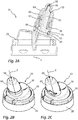
- Fig. 1A and 1B show an overall view of a dispenser 100 according to the invention in a sectional and uncut representation.
- the relationships explained below for different embodiments of the discharge head 10 of this dispenser 100 apply. Details of two possible embodiments of the dispensing head 10 are subsequently described with reference to FIG Fig. 2A to 2I and Figs. 3A to 3H are explained.
- An inventive dispenser 100 has a pressure accumulator 110 whose outer surfaces are formed by a metallic body 118 and a cover 120.
- an outlet valve 112 is attached, which can be opened by depressing a valve stub 114 against the force of a valve spring 116, so that the liquid flows into the discharge head 10.
- the dispenser 100 has at the discharge head 10 a slender, elongated nasal applicator 12 whose main direction of extension is set in relation to the main extension direction 3 of the pressure accumulator 110.
- the nasal applicator 12 is for insertion into a nostril of a User provided.
- Other types of applicator may be provided here depending on the application instead of the Nasalapplikators 12.
- the discharge head 10 is snapped onto the pressure accumulator 110 in the region of a crimp connection between the body 118 and the cover 120, for which purpose a coupling device is provided on a base 20 of the discharge head.
- the base 20 of the discharge head 10 is integrally connected to the majority of the functional elements of the discharge head 10.
- an actuating handle 30 with actuating surface 32 is integrally formed on the base 20 via a plastic bridge 28.
- plunger 40 is integrally formed, which is inserted into the outlet valve 112 of the pressure accumulator 110 for the purpose of actuation and for the purpose of the inflow of liquid.
- the mecanicalapplikators 12 of the discharge head 10 is formed integrally with the actuating handle 30, in this regard, a further explained below difference between the designs of Fig. 2A to 2I and the Figs. 3A to 3H consists.
- the mecanicbauteit 50 includes an outer sleeve portion 56 and an inner pin 52nd
- a component of the discharge head 10 which is separate from this composite component is the outer component 60 of the nasal applicator 12, at the end face of which an end wall is interrupted by a discharge opening 98.
- the outer member 60 is pushed onto the inner member 50 and in the design of the Fig. 2A to 2I positively secured to the inner member 50, as will be explained below.
- the actuating handle 30 of the dispenser 100 is pivotable in the direction of the arrow 6 due to the deformability of the plastic bridge 28, so that the Nasalapplikator 12 and the plunger 40 are pivoted with.
- the outlet valve 112 is opened and liquid flows through the inner channel 90 of the plunger 40 upwards, then enters an inflow region 58 between the central pin 52 and the sleeve portion 56 of the inner member 50 of the Nasalapplikators 12 and from there through an applicator channel 92 defined jointly by the inner component 50 and the outer component 60 is conveyed to the discharge opening 98, from where the liquid can be discharged.
- the outer component For sealing the components 50, 60 against each other, the outer component a sleeve 66, the outside of which rests liquid-tight on the inside sealing surface of the sleeve portion 56.
- the outer member 60 is formed as a limited relatively movable outer member 60.
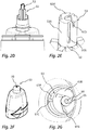
- Fig. 2A to 2I show in detail a first embodiment of a discharge head according to the invention, according to the Fig. 1A and 1B which is to be attached to a pressure accumulator 110 to form a dispenser 100.
- the discharge head 10 the two components already described, namely - as in Fig. 2A clearly visible - the first component, which forms the base 20, the actuating handle 30 with actuating surface 32 and integrally an inner component 50 of the applicator, and the second component, the outer member 60, which is pushed onto the inner component 50 of the applicator and here in the range of Clamping surfaces 55, 65 is locked.
- Figs. 2B and 2C can be switched between different discharge characteristics, namely present between a discharge of the liquid in the form of a spray jet on the one hand and the discharge in the form of an atomized jet on the other.
- the switching of the configurations takes place in that the outer component 60 is rotated relative to the inner component 50 by 180 ° about the axis 2. An axial displacement of inner component 50 and outer member 60 does not take place here.
- FIGS. 2D to 2G clarify this.
- Fig. 2E shows the front area 53 of the inner component 50.
- This has an initial circular cylindrical basic shape whose dimensions relative to the diameter of an end face 53B correspond to the dimensions of the corresponding distal interior 63 of the outer member 60, so that the End region 53 is inserted under circumferential and frontal sealing system in the distal interior 63.
- axially extending supply grooves 97A are provided, which extend to the end face 53B. It is a total of three supply grooves 97A at a distance of 120 ° to each other. Offset by about 30 ° thereto, three radial Zuströmnuten 97 D are provided in the end face 53 B of the end portion 53 of the inner member 50, which are also spaced apart by 120 ° and each extending to the cylindrical outer surface 53 A.
- three grooves 97C offset by 120 ° from each other are provided on the outer component in an inner circumferential surface 63A, which do not extend to the front-side inner surface 63B, but shortly before each of them Find the end.
- the front-side inner surface 63B itself three tangentially oriented Zuströmnuten 97B are provided which open tangentially into a swirl chamber 96 and are also spaced from each other by 120 °.
- This groove configuration is provided in order to open and close different fluid paths as a function of the rotational position of the outer component 60 relative to the inner component 50.
- the Fig. 2H shows that configuration in which the outer member 60 is rotated relative to the inner member 50 so that intended, an atomized jet is to be discharged.
- the supply grooves 97C are arranged such that liquid at its end can flow into the radial inflow grooves 97D and thus reach the discharge opening 98 without forming a twist. Meanwhile, in this rotational position, the tangential grooves 97B are not supplied with liquid since they are arranged rotatably offset from their supply grooves 97A.
- the groove design described thus makes it possible to provide very functionally reliable and mutually sealed fluid paths both for the formation of a spray jet and for the formation of a jet available, the paths can be opened and closed only by a rotational movement of the outer member relative to the inner member.
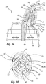
- Fig. 3A to 3G together with a variant of Fig. 3H has a modification, which serves in particular the purpose of ensuring the tightness in the region of the end face 53B and to prevent by a switching valve to prevent a discharge particularly safe.
- FIGS. 3A and 3B show the position of inner member 50 and outer member 60 in a position to produce a spray jet.
- 3C and 3D show the position of inner member 50 and outer member 60 in a position to produce an un-atomized jet.
- the inner member 50 is not integrally connected to the base 20 and the actuating handle 30, but instead formed as a separate component 50 which is axially slid onto a pin 82 which is part of a guide member 80, which in this particular case integral with the actuating surface 32 and the base 20 is executed.
- the guide member 80 could be formed separately from the components 32 and 20 and attached to one of them only fixed.
- a spring means 70 which is formed by clamping surfaces 65, 85 which are provided in this case on the guide member 80 and the outer member 60 and the outer member 60 press the front side against the inner member 50.
- the interior component 50 which is in Fig. 3F again shown separately, has a sleeve structure open on both sides. With its end pointing away from the discharge opening 98, it is pushed onto the said pin 82 of the guide component 80. It is by ribs 87 and recesses 57 in the in Fig. 3B and 3D clarified way created an anti-rotation.
- the inner member 50 is thus secured against rotation, but in principle axially displaceable, attached to the guide member 80.
- the inner component 50 has at its end a piston surface 54 and abuts with an outer side sealingly against a sliding surface 84 of a sleeve portion 86 of the guide component 80.
- the inner component 50 At the opposite end of the inner component 50, this merges into an end region 53 which, in terms of its structure and in particular of the supply grooves 97A and 97D, corresponds to the structure Fig. 2E equivalent.
- the inner component In order to be able to convey liquid here, the inner component is also designed to be open in this direction and has an opening 59 for this purpose. Beyond this opening, a further piston surface 51 is provided, which abuts the outside on a sliding surface 61 of the outer component 60.
- This second piston surface 51 or its effective cross section is smaller than the piston surface 54 or its effective cross section.
- Fig. 3B and 3D illustrate further locking positions of the inner member 50 and the outer member 60 to each other, wherein in the case of the design of Figs. 3A to 3H
- These detent positions are made possible by outer recesses 89 on the sleeve portion 86 of the guide member 80 and inwardly facing latching webs 69 on the outer member 60.
- the locking webs 69 in the wells 89th are indented, it requires an increased force to rotate the outer member 60 relative to the inner member 50 and the guide member 80. If the components are rotated relative to one another, snap the locking webs 69 into the recesses 89 and thus signal the user that it is a special rotational position.
- Fig. 3B and 3D which are the position for discharging a spray jet or a jet
- two other positions are possible, which are rotated by 90 ° contrast. In these positions, the discharge head is locked, as will be explained below.
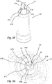
- Fig. 3E shows a further sectional view. It can be seen here that the outer component 60 is provided with inwardly pointing radial ribs 62. These have a shape with which they form said locking webs 69 for forming the locking positions in an upper region. In contrast, a lower region 67 bears against the clamping surface 85 on the outside. The effect of this lower portion 67 is that the outer member 60 is only slightly deformable and therefore there is no risk that it dissolves under the action of fluid pressure from the inner member 50 and the guide member 80.
- Figs. 3F and 3G show similar to the Figures 2E and 2G the inflow grooves 97B, 97D and the supply grooves 97A, 97C. Their operation corresponds to that already explained:
- the liquid is passed either along a first liquid path through the supply grooves 97A into the Zutrömnuten 97B or along a second liquid path through the supply grooves 97C in the Zuströmnuten 97D. If none of these liquid paths is open, the liquid can not reach the discharge opening 98.
- a switching valve 99 is provided, which is formed by two stages 99A, 99C in the outer member 60 and inner member 50 and by therein provided interruptions 99B, 99D. In two 180 ° spaced apart rotational positions, namely precisely those rotational positions for the discharge as a jet or spray, the interruptions 99 B, 99 D are aligned such that liquid can flow through the switching valve 99. In all other positions, the switching valve 99 stops the supply of liquid to the supply grooves 97A, 97C.
- the piston-like configuration of the inner component 50 is suitable for permanently pressing it in the direction of the discharge opening 98 when fluid pressure is applied.
- a special degree of tightness between the abutting surfaces 53B, 63B is created.
- the special tightness ensures that the application of a jet as well as a spray jet in particularly good quality is possible. Liquid only passes through the grooves 97A-97D to the discharge port 98, but not through an unwanted gap between the end surface 53B and the front-side inner surface 63B.
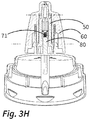
- Fig. 3H shows a slightly modified variant of the embodiment of Fig. 3A to 3G ,
- an additional spring device 71 in the form of a helical compression spring is provided between the guide component 80 and the inner component 50, which presses the inner component 50 permanently against the outer component 60 on the front side.
- the piston-like action of the inner component 50 can be dispensed with. Preferably, however, this remains despite the spring device 71 is obtained.
Landscapes
- Health & Medical Sciences (AREA)
- Engineering & Computer Science (AREA)
- Animal Behavior & Ethology (AREA)
- General Health & Medical Sciences (AREA)
- Veterinary Medicine (AREA)
- Anesthesiology (AREA)
- Biomedical Technology (AREA)
- Heart & Thoracic Surgery (AREA)
- Hematology (AREA)
- Life Sciences & Earth Sciences (AREA)
- Public Health (AREA)
- Mechanical Engineering (AREA)
- Bioinformatics & Cheminformatics (AREA)
- Pulmonology (AREA)
- Chemical & Material Sciences (AREA)
- Dispersion Chemistry (AREA)
- Otolaryngology (AREA)
- Vascular Medicine (AREA)
- Containers And Packaging Bodies Having A Special Means To Remove Contents (AREA)
- Infusion, Injection, And Reservoir Apparatuses (AREA)
Priority Applications (1)
| Application Number | Priority Date | Filing Date | Title |
|---|---|---|---|
| RU2019109788A RU2737583C2 (ru) | 2017-06-08 | 2019-04-03 | Выпускная головка для интраназального введения жидкости из емкости, находящейся под давлением |
Applications Claiming Priority (2)
| Application Number | Priority Date | Filing Date | Title |
|---|---|---|---|
| EP17175093.8A EP3412325B1 (fr) | 2017-06-08 | 2017-06-08 | Tête distributrice pour l'application nasale de liquide provenant d'un accumulateur de pression |
| PCT/EP2018/059583 WO2018224206A1 (fr) | 2017-06-08 | 2018-04-13 | Tête de diffusion pour l'application nasale d'un liquide à partir d'un accumulateur de pression |
Publications (2)
| Publication Number | Publication Date |
|---|---|
| EP3552644A1 true EP3552644A1 (fr) | 2019-10-16 |
| EP3552644B1 EP3552644B1 (fr) | 2021-07-07 |
Family
ID=59053970
Family Applications (2)
| Application Number | Title | Priority Date | Filing Date |
|---|---|---|---|
| EP17175093.8A Active EP3412325B1 (fr) | 2017-06-08 | 2017-06-08 | Tête distributrice pour l'application nasale de liquide provenant d'un accumulateur de pression |
| EP18209877.2A Active EP3552644B1 (fr) | 2017-06-08 | 2018-12-03 | Tête distributrice pour l'application nasale de liquide provenant d'un accumulateur de pression |
Family Applications Before (1)
| Application Number | Title | Priority Date | Filing Date |
|---|---|---|---|
| EP17175093.8A Active EP3412325B1 (fr) | 2017-06-08 | 2017-06-08 | Tête distributrice pour l'application nasale de liquide provenant d'un accumulateur de pression |
Country Status (6)
| Country | Link |
|---|---|
| US (2) | US11833295B2 (fr) |
| EP (2) | EP3412325B1 (fr) |
| CN (2) | CN114655585B (fr) |
| BR (1) | BR112019023811B1 (fr) |
| RU (1) | RU2737583C2 (fr) |
| WO (1) | WO2018224206A1 (fr) |
Cited By (1)
| Publication number | Priority date | Publication date | Assignee | Title |
|---|---|---|---|---|
| CN116211683A (zh) * | 2023-03-22 | 2023-06-06 | 中山市美捷时包装制品有限公司 | 一种可调节的鼻腔清洗促动器 |
Families Citing this family (10)
| Publication number | Priority date | Publication date | Assignee | Title |
|---|---|---|---|---|
| US10464736B1 (en) * | 2017-09-21 | 2019-11-05 | The B'Laster Corporation | Spray can actuator |
| USD935318S1 (en) | 2019-07-24 | 2021-11-09 | Aptar Radolfzell Gmbh | Spray head |
| GB2597471A (en) * | 2020-07-22 | 2022-02-02 | Innovolo Ltd | Aerosol canister cap |
| BE1029771B1 (nl) * | 2021-09-20 | 2023-04-17 | Soudal | Handbedieningsapplicator voor polyurethaan (pu) schuim |
| GB202202890D0 (en) * | 2022-03-02 | 2022-04-13 | Consort Medical Ltd | Improvements relating to nasal pieces |
| EP4368227B1 (fr) * | 2022-11-09 | 2025-02-26 | Aptar Radolfzell GmbH | Distributeur de liquide pour application nasale et dispositif de pompage |
| USD1006983S1 (en) * | 2023-03-13 | 2023-12-05 | ChongQing Moffy Innovation Technology Co., Ltd. | Nasal irrigator nozzle |
| US12454916B2 (en) * | 2023-12-14 | 2025-10-28 | Collins Engine Nozzles, Inc. | Multi-component swirl valves |
| CN118001520A (zh) * | 2024-03-05 | 2024-05-10 | 深圳博纳精密给药系统股份有限公司 | 可调节喷液状态的鼻喷头 |
| EP4670765A1 (fr) | 2024-06-27 | 2025-12-31 | Aptar Radolfzell GmbH | Tête de distribution et distributeur de liquide pour l'application nasale de liquide, procédé de fabrication d'une tête de distribution |
Citations (8)
| Publication number | Priority date | Publication date | Assignee | Title |
|---|---|---|---|---|
| US3961756A (en) * | 1975-02-10 | 1976-06-08 | National Chemsearch Corporation | Adjustable-spray mechanism |
| EP0040851A1 (fr) * | 1980-05-27 | 1981-12-02 | Specialty Packaging Products, Inc. | Dispositif distributeur de liquide |
| US4706888A (en) * | 1986-07-11 | 1987-11-17 | Calmar, Inc. | Multi-purpose nozzle assembly |
| EP0729792A2 (fr) * | 1995-02-28 | 1996-09-04 | Calmar Inc. | Pulvérisateur à configuration de jet variable |
| WO2009025697A1 (fr) * | 2007-08-22 | 2009-02-26 | Seaquistperfect Dispensing L.L.C. | Distributeur pouvant être verrouillé |
| USD659531S1 (en) | 2010-05-10 | 2012-05-15 | Ep Systems Sa | Nozzle |
| DE102012200545A1 (de) | 2012-01-16 | 2013-07-18 | Aptar Radolfzell Gmbh | Medienspender |
| US20160325916A1 (en) * | 2014-01-17 | 2016-11-10 | Aptar Dortmund Gmbh | Dispensing device |
Family Cites Families (12)
| Publication number | Priority date | Publication date | Assignee | Title |
|---|---|---|---|---|
| FR2781772B1 (fr) | 1998-07-31 | 2000-10-13 | Sofab | Distributeur de produits liquides destines a etre delivres par pulverisation |
| US5996653A (en) | 1998-10-08 | 1999-12-07 | Eastman Kodak Company | Valve assembly and apparatus |
| RU28026U1 (ru) | 2002-08-15 | 2003-03-10 | Общество с ограниченной ответственностью "Паркинфарм" | Устройство для дозированного введения лекарственного средства |
| FR2886172B1 (fr) * | 2005-05-25 | 2008-01-25 | Soppec Soc Par Actions Simplif | Dispositif diffuseur a jets multiples pour bombes aerosols |
| FR2952042B1 (fr) * | 2009-11-03 | 2012-01-20 | Valois Sas | Dispositif de distribution de produit fluide. |
| DE102011007396A1 (de) | 2011-04-14 | 2012-10-18 | Ing. Erich Pfeiffer Gmbh | Austragkopf für eine Tube und Tube mit Austragkopf |
| DE102011082420B4 (de) | 2011-09-09 | 2021-02-04 | Aptar Radolfzell Gmbh | Flüssigkeitsspender und Austragskopf für einen Flüssigkeitsspender |
| DE102013001931B4 (de) | 2013-02-02 | 2016-03-31 | Neoperl Gmbh | Sanitäre Einsetzeinheit |
| EP2796206B1 (fr) | 2013-04-26 | 2016-12-21 | Aptar Radolfzell GmbH | Tête de distribution associée à un récipient et procédé de fixation d'une tête de distribution sur un récipient |
| EP2868334B1 (fr) | 2013-11-05 | 2017-01-11 | Benedict Gerber | Douche nasale |
| FR3034326B1 (fr) | 2015-03-30 | 2020-02-07 | Yslab | Tete de pulverisation universelle et securitaire pour pulverisateur |
| ITUB20152886A1 (it) * | 2015-08-05 | 2017-02-05 | Eleuterio Pollini | Dispositivo di sicurezza per l'irrigazione nasale |
-
2017
- 2017-06-08 EP EP17175093.8A patent/EP3412325B1/fr active Active
-
2018
- 2018-04-13 US US16/615,245 patent/US11833295B2/en active Active
- 2018-04-13 WO PCT/EP2018/059583 patent/WO2018224206A1/fr not_active Ceased
- 2018-04-13 BR BR112019023811-5A patent/BR112019023811B1/pt active IP Right Grant
- 2018-04-13 CN CN202210280372.9A patent/CN114655585B/zh active Active
- 2018-04-13 CN CN201880038259.1A patent/CN110740772B/zh active Active
- 2018-12-03 EP EP18209877.2A patent/EP3552644B1/fr active Active
-
2019
- 2019-04-03 RU RU2019109788A patent/RU2737583C2/ru active
-
2023
- 2023-08-21 US US18/452,797 patent/US20230398316A1/en active Pending
Patent Citations (8)
| Publication number | Priority date | Publication date | Assignee | Title |
|---|---|---|---|---|
| US3961756A (en) * | 1975-02-10 | 1976-06-08 | National Chemsearch Corporation | Adjustable-spray mechanism |
| EP0040851A1 (fr) * | 1980-05-27 | 1981-12-02 | Specialty Packaging Products, Inc. | Dispositif distributeur de liquide |
| US4706888A (en) * | 1986-07-11 | 1987-11-17 | Calmar, Inc. | Multi-purpose nozzle assembly |
| EP0729792A2 (fr) * | 1995-02-28 | 1996-09-04 | Calmar Inc. | Pulvérisateur à configuration de jet variable |
| WO2009025697A1 (fr) * | 2007-08-22 | 2009-02-26 | Seaquistperfect Dispensing L.L.C. | Distributeur pouvant être verrouillé |
| USD659531S1 (en) | 2010-05-10 | 2012-05-15 | Ep Systems Sa | Nozzle |
| DE102012200545A1 (de) | 2012-01-16 | 2013-07-18 | Aptar Radolfzell Gmbh | Medienspender |
| US20160325916A1 (en) * | 2014-01-17 | 2016-11-10 | Aptar Dortmund Gmbh | Dispensing device |
Cited By (1)
| Publication number | Priority date | Publication date | Assignee | Title |
|---|---|---|---|---|
| CN116211683A (zh) * | 2023-03-22 | 2023-06-06 | 中山市美捷时包装制品有限公司 | 一种可调节的鼻腔清洗促动器 |
Also Published As
| Publication number | Publication date |
|---|---|
| RU2019109788A3 (fr) | 2020-10-05 |
| WO2018224206A1 (fr) | 2018-12-13 |
| US20200171252A1 (en) | 2020-06-04 |
| CN110740772B (zh) | 2022-03-29 |
| US20230398316A1 (en) | 2023-12-14 |
| EP3412325B1 (fr) | 2019-09-25 |
| RU2019109788A (ru) | 2020-10-05 |
| BR112019023811A2 (pt) | 2020-06-02 |
| CN110740772A (zh) | 2020-01-31 |
| EP3552644B1 (fr) | 2021-07-07 |
| RU2737583C2 (ru) | 2020-12-01 |
| CN114655585B (zh) | 2024-12-24 |
| CN114655585A (zh) | 2022-06-24 |
| EP3412325A1 (fr) | 2018-12-12 |
| BR112019023811B1 (pt) | 2024-01-02 |
| US11833295B2 (en) | 2023-12-05 |
Similar Documents
| Publication | Publication Date | Title |
|---|---|---|
| EP3552644B1 (fr) | Tête distributrice pour l'application nasale de liquide provenant d'un accumulateur de pression | |
| EP0923993B1 (fr) | Distributeur de fluide | |
| DE69820189T2 (de) | System und Verfahren für Sprüh- oder Aerosolspitze mit Einweg-Strömung | |
| DE69919321T2 (de) | Zerstäubungskopf für einen spender für medien | |
| EP0882516B1 (fr) | Distributer de fluide | |
| EP2804504B1 (fr) | Distributeur de fluides | |
| DE60320607T2 (de) | Einheit zur Verpackung und zur Ausgabe eines Produkts, insbesondere in Form einer Probe | |
| EP0815946A2 (fr) | Distributeur pour fluides | |
| DE602004005607T2 (de) | Fluidproduktabgabekopf | |
| DE102016009957A1 (de) | Spritzpistole mit Abzugssperre, Abzugssperre für eine Spritzpistole und Verfahren zum Anbringen, zum Aktivieren und zum Deaktivieren einer Abzugssperre | |
| DE3315334A1 (de) | Zerstaeuber- oder dosierpumpe | |
| EP0312722A1 (fr) | Pompe de dosage et d'atomisation pour matières liquides ou visqueuses | |
| DE2904127A1 (de) | Einstellbare fluessigkeitsabgabeduese | |
| DE2641171B2 (de) | Schreibgerät | |
| EP0901836B1 (fr) | Distributeur de fluide | |
| EP0985454A2 (fr) | Distributeur de fluide | |
| EP0901835B1 (fr) | Distributeur de produit | |
| EP3935972B1 (fr) | Distributeur oral pour liquides, en particulier pour des liquides contenant de la nicotine ou du cannabis | |
| EP0451615A2 (fr) | Dispositif pour décharger au moins un produit | |
| DE10015968A1 (de) | Spender für Medien | |
| EP0982075B1 (fr) | Distributeur de fluides | |
| EP0829307B1 (fr) | Distributeur de fluides | |
| EP0923994A1 (fr) | Distributeur de fluide | |
| DE19845910A1 (de) | Spender für Medien | |
| EP4169399B1 (fr) | Distributeur d'un liquide contenant de la nicotine et/ou du cannabis |
Legal Events
| Date | Code | Title | Description |
|---|---|---|---|
| PUAI | Public reference made under article 153(3) epc to a published international application that has entered the european phase |
Free format text: ORIGINAL CODE: 0009012 |
|
| STAA | Information on the status of an ep patent application or granted ep patent |
Free format text: STATUS: THE APPLICATION HAS BEEN PUBLISHED |
|
| AK | Designated contracting states |
Kind code of ref document: A1 Designated state(s): AL AT BE BG CH CY CZ DE DK EE ES FI FR GB GR HR HU IE IS IT LI LT LU LV MC MK MT NL NO PL PT RO RS SE SI SK SM TR |
|
| AX | Request for extension of the european patent |
Extension state: BA ME |
|
| STAA | Information on the status of an ep patent application or granted ep patent |
Free format text: STATUS: REQUEST FOR EXAMINATION WAS MADE |
|
| 17P | Request for examination filed |
Effective date: 20200416 |
|
| RBV | Designated contracting states (corrected) |
Designated state(s): AL AT BE BG CH CY CZ DE DK EE ES FI FR GB GR HR HU IE IS IT LI LT LU LV MC MK MT NL NO PL PT RO RS SE SI SK SM TR |
|
| GRAP | Despatch of communication of intention to grant a patent |
Free format text: ORIGINAL CODE: EPIDOSNIGR1 |
|
| STAA | Information on the status of an ep patent application or granted ep patent |
Free format text: STATUS: GRANT OF PATENT IS INTENDED |
|
| RIC1 | Information provided on ipc code assigned before grant |
Ipc: A61M 15/00 20060101AFI20210308BHEP Ipc: A61M 15/08 20060101ALI20210308BHEP Ipc: B65D 83/14 20060101ALI20210308BHEP Ipc: A61M 11/00 20060101ALI20210308BHEP Ipc: B65D 83/20 20060101ALI20210308BHEP Ipc: B65D 83/22 20060101ALI20210308BHEP Ipc: B05B 1/12 20060101ALI20210308BHEP Ipc: B05B 1/34 20060101ALI20210308BHEP Ipc: B05B 1/00 20060101ALI20210308BHEP Ipc: B65D 83/30 20060101ALN20210308BHEP Ipc: B65D 83/46 20060101ALN20210308BHEP |
|
| INTG | Intention to grant announced |
Effective date: 20210324 |
|
| RIN1 | Information on inventor provided before grant (corrected) |
Inventor name: GREINER-PERTH, JUERGEN Inventor name: SCHMID, FELIX |
|
| GRAS | Grant fee paid |
Free format text: ORIGINAL CODE: EPIDOSNIGR3 |
|
| GRAA | (expected) grant |
Free format text: ORIGINAL CODE: 0009210 |
|
| STAA | Information on the status of an ep patent application or granted ep patent |
Free format text: STATUS: THE PATENT HAS BEEN GRANTED |
|
| AK | Designated contracting states |
Kind code of ref document: B1 Designated state(s): AL AT BE BG CH CY CZ DE DK EE ES FI FR GB GR HR HU IE IS IT LI LT LU LV MC MK MT NL NO PL PT RO RS SE SI SK SM TR |
|
| REG | Reference to a national code |
Ref country code: GB Ref legal event code: FG4D Free format text: NOT ENGLISH |
|
| REG | Reference to a national code |
Ref country code: AT Ref legal event code: REF Ref document number: 1407947 Country of ref document: AT Kind code of ref document: T Effective date: 20210715 |
|
| REG | Reference to a national code |
Ref country code: DE Ref legal event code: R096 Ref document number: 502018006001 Country of ref document: DE |
|
| REG | Reference to a national code |
Ref country code: IE Ref legal event code: FG4D Free format text: LANGUAGE OF EP DOCUMENT: GERMAN |
|
| REG | Reference to a national code |
Ref country code: LT Ref legal event code: MG9D |
|
| REG | Reference to a national code |
Ref country code: NL Ref legal event code: MP Effective date: 20210707 |
|
| PG25 | Lapsed in a contracting state [announced via postgrant information from national office to epo] |
Ref country code: HR Free format text: LAPSE BECAUSE OF FAILURE TO SUBMIT A TRANSLATION OF THE DESCRIPTION OR TO PAY THE FEE WITHIN THE PRESCRIBED TIME-LIMIT Effective date: 20210707 Ref country code: ES Free format text: LAPSE BECAUSE OF FAILURE TO SUBMIT A TRANSLATION OF THE DESCRIPTION OR TO PAY THE FEE WITHIN THE PRESCRIBED TIME-LIMIT Effective date: 20210707 Ref country code: FI Free format text: LAPSE BECAUSE OF FAILURE TO SUBMIT A TRANSLATION OF THE DESCRIPTION OR TO PAY THE FEE WITHIN THE PRESCRIBED TIME-LIMIT Effective date: 20210707 Ref country code: RS Free format text: LAPSE BECAUSE OF FAILURE TO SUBMIT A TRANSLATION OF THE DESCRIPTION OR TO PAY THE FEE WITHIN THE PRESCRIBED TIME-LIMIT Effective date: 20210707 Ref country code: SE Free format text: LAPSE BECAUSE OF FAILURE TO SUBMIT A TRANSLATION OF THE DESCRIPTION OR TO PAY THE FEE WITHIN THE PRESCRIBED TIME-LIMIT Effective date: 20210707 Ref country code: PT Free format text: LAPSE BECAUSE OF FAILURE TO SUBMIT A TRANSLATION OF THE DESCRIPTION OR TO PAY THE FEE WITHIN THE PRESCRIBED TIME-LIMIT Effective date: 20211108 Ref country code: NO Free format text: LAPSE BECAUSE OF FAILURE TO SUBMIT A TRANSLATION OF THE DESCRIPTION OR TO PAY THE FEE WITHIN THE PRESCRIBED TIME-LIMIT Effective date: 20211007 Ref country code: NL Free format text: LAPSE BECAUSE OF FAILURE TO SUBMIT A TRANSLATION OF THE DESCRIPTION OR TO PAY THE FEE WITHIN THE PRESCRIBED TIME-LIMIT Effective date: 20210707 Ref country code: LT Free format text: LAPSE BECAUSE OF FAILURE TO SUBMIT A TRANSLATION OF THE DESCRIPTION OR TO PAY THE FEE WITHIN THE PRESCRIBED TIME-LIMIT Effective date: 20210707 Ref country code: BG Free format text: LAPSE BECAUSE OF FAILURE TO SUBMIT A TRANSLATION OF THE DESCRIPTION OR TO PAY THE FEE WITHIN THE PRESCRIBED TIME-LIMIT Effective date: 20211007 |
|
| PG25 | Lapsed in a contracting state [announced via postgrant information from national office to epo] |
Ref country code: PL Free format text: LAPSE BECAUSE OF FAILURE TO SUBMIT A TRANSLATION OF THE DESCRIPTION OR TO PAY THE FEE WITHIN THE PRESCRIBED TIME-LIMIT Effective date: 20210707 Ref country code: LV Free format text: LAPSE BECAUSE OF FAILURE TO SUBMIT A TRANSLATION OF THE DESCRIPTION OR TO PAY THE FEE WITHIN THE PRESCRIBED TIME-LIMIT Effective date: 20210707 Ref country code: GR Free format text: LAPSE BECAUSE OF FAILURE TO SUBMIT A TRANSLATION OF THE DESCRIPTION OR TO PAY THE FEE WITHIN THE PRESCRIBED TIME-LIMIT Effective date: 20211008 |
|
| REG | Reference to a national code |
Ref country code: DE Ref legal event code: R097 Ref document number: 502018006001 Country of ref document: DE |
|
| REG | Reference to a national code |
Ref country code: DE Ref legal event code: R082 Ref document number: 502018006001 Country of ref document: DE Representative=s name: WITTE, WELLER & PARTNER PATENTANWAELTE MBB, DE |
|
| PG25 | Lapsed in a contracting state [announced via postgrant information from national office to epo] |
Ref country code: DK Free format text: LAPSE BECAUSE OF FAILURE TO SUBMIT A TRANSLATION OF THE DESCRIPTION OR TO PAY THE FEE WITHIN THE PRESCRIBED TIME-LIMIT Effective date: 20210707 |
|
| PLBE | No opposition filed within time limit |
Free format text: ORIGINAL CODE: 0009261 |
|
| STAA | Information on the status of an ep patent application or granted ep patent |
Free format text: STATUS: NO OPPOSITION FILED WITHIN TIME LIMIT |
|
| PG25 | Lapsed in a contracting state [announced via postgrant information from national office to epo] |
Ref country code: SM Free format text: LAPSE BECAUSE OF FAILURE TO SUBMIT A TRANSLATION OF THE DESCRIPTION OR TO PAY THE FEE WITHIN THE PRESCRIBED TIME-LIMIT Effective date: 20210707 Ref country code: SK Free format text: LAPSE BECAUSE OF FAILURE TO SUBMIT A TRANSLATION OF THE DESCRIPTION OR TO PAY THE FEE WITHIN THE PRESCRIBED TIME-LIMIT Effective date: 20210707 Ref country code: RO Free format text: LAPSE BECAUSE OF FAILURE TO SUBMIT A TRANSLATION OF THE DESCRIPTION OR TO PAY THE FEE WITHIN THE PRESCRIBED TIME-LIMIT Effective date: 20210707 Ref country code: EE Free format text: LAPSE BECAUSE OF FAILURE TO SUBMIT A TRANSLATION OF THE DESCRIPTION OR TO PAY THE FEE WITHIN THE PRESCRIBED TIME-LIMIT Effective date: 20210707 Ref country code: CZ Free format text: LAPSE BECAUSE OF FAILURE TO SUBMIT A TRANSLATION OF THE DESCRIPTION OR TO PAY THE FEE WITHIN THE PRESCRIBED TIME-LIMIT Effective date: 20210707 Ref country code: AL Free format text: LAPSE BECAUSE OF FAILURE TO SUBMIT A TRANSLATION OF THE DESCRIPTION OR TO PAY THE FEE WITHIN THE PRESCRIBED TIME-LIMIT Effective date: 20210707 |
|
| 26N | No opposition filed |
Effective date: 20220408 |
|
| PG25 | Lapsed in a contracting state [announced via postgrant information from national office to epo] |
Ref country code: MC Free format text: LAPSE BECAUSE OF FAILURE TO SUBMIT A TRANSLATION OF THE DESCRIPTION OR TO PAY THE FEE WITHIN THE PRESCRIBED TIME-LIMIT Effective date: 20210707 |
|
| REG | Reference to a national code |
Ref country code: CH Ref legal event code: PL |
|
| REG | Reference to a national code |
Ref country code: BE Ref legal event code: MM Effective date: 20211231 |
|
| PG25 | Lapsed in a contracting state [announced via postgrant information from national office to epo] |
Ref country code: LU Free format text: LAPSE BECAUSE OF NON-PAYMENT OF DUE FEES Effective date: 20211203 Ref country code: IE Free format text: LAPSE BECAUSE OF NON-PAYMENT OF DUE FEES Effective date: 20211203 |
|
| PG25 | Lapsed in a contracting state [announced via postgrant information from national office to epo] |
Ref country code: BE Free format text: LAPSE BECAUSE OF NON-PAYMENT OF DUE FEES Effective date: 20211231 |
|
| PG25 | Lapsed in a contracting state [announced via postgrant information from national office to epo] |
Ref country code: LI Free format text: LAPSE BECAUSE OF NON-PAYMENT OF DUE FEES Effective date: 20211231 Ref country code: CH Free format text: LAPSE BECAUSE OF NON-PAYMENT OF DUE FEES Effective date: 20211231 |
|
| P01 | Opt-out of the competence of the unified patent court (upc) registered |
Effective date: 20230502 |
|
| PG25 | Lapsed in a contracting state [announced via postgrant information from national office to epo] |
Ref country code: CY Free format text: LAPSE BECAUSE OF FAILURE TO SUBMIT A TRANSLATION OF THE DESCRIPTION OR TO PAY THE FEE WITHIN THE PRESCRIBED TIME-LIMIT Effective date: 20210707 |
|
| PG25 | Lapsed in a contracting state [announced via postgrant information from national office to epo] |
Ref country code: HU Free format text: LAPSE BECAUSE OF FAILURE TO SUBMIT A TRANSLATION OF THE DESCRIPTION OR TO PAY THE FEE WITHIN THE PRESCRIBED TIME-LIMIT; INVALID AB INITIO Effective date: 20181203 |
|
| PG25 | Lapsed in a contracting state [announced via postgrant information from national office to epo] |
Ref country code: MK Free format text: LAPSE BECAUSE OF FAILURE TO SUBMIT A TRANSLATION OF THE DESCRIPTION OR TO PAY THE FEE WITHIN THE PRESCRIBED TIME-LIMIT Effective date: 20210707 |
|
| PG25 | Lapsed in a contracting state [announced via postgrant information from national office to epo] |
Ref country code: MT Free format text: LAPSE BECAUSE OF FAILURE TO SUBMIT A TRANSLATION OF THE DESCRIPTION OR TO PAY THE FEE WITHIN THE PRESCRIBED TIME-LIMIT Effective date: 20210707 |
|
| REG | Reference to a national code |
Ref country code: AT Ref legal event code: MM01 Ref document number: 1407947 Country of ref document: AT Kind code of ref document: T Effective date: 20231203 |
|
| PG25 | Lapsed in a contracting state [announced via postgrant information from national office to epo] |
Ref country code: AT Free format text: LAPSE BECAUSE OF NON-PAYMENT OF DUE FEES Effective date: 20231203 |
|
| PG25 | Lapsed in a contracting state [announced via postgrant information from national office to epo] |
Ref country code: TR Free format text: LAPSE BECAUSE OF FAILURE TO SUBMIT A TRANSLATION OF THE DESCRIPTION OR TO PAY THE FEE WITHIN THE PRESCRIBED TIME-LIMIT Effective date: 20210707 |
|
| PGFP | Annual fee paid to national office [announced via postgrant information from national office to epo] |
Ref country code: DE Payment date: 20251217 Year of fee payment: 8 |
|
| PGFP | Annual fee paid to national office [announced via postgrant information from national office to epo] |
Ref country code: GB Payment date: 20251219 Year of fee payment: 8 |
|
| PGFP | Annual fee paid to national office [announced via postgrant information from national office to epo] |
Ref country code: IT Payment date: 20251223 Year of fee payment: 8 |
|
| PGFP | Annual fee paid to national office [announced via postgrant information from national office to epo] |
Ref country code: FR Payment date: 20251229 Year of fee payment: 8 |
|
| PGFP | Annual fee paid to national office [announced via postgrant information from national office to epo] |
Ref country code: AT Payment date: 20260410 Year of fee payment: 5 |