EP3552715A1 - Accouplement permettant de raccorder des conduites, installation de revêtement par poudre pourvue d'accouplement et procédé de nettoyage du système de revêtement par poudre - Google Patents
Accouplement permettant de raccorder des conduites, installation de revêtement par poudre pourvue d'accouplement et procédé de nettoyage du système de revêtement par poudre Download PDFInfo
- Publication number
- EP3552715A1 EP3552715A1 EP18167080.3A EP18167080A EP3552715A1 EP 3552715 A1 EP3552715 A1 EP 3552715A1 EP 18167080 A EP18167080 A EP 18167080A EP 3552715 A1 EP3552715 A1 EP 3552715A1
- Authority
- EP
- European Patent Office
- Prior art keywords
- powder
- line
- coupling
- cleaning
- clutch
- Prior art date
- Legal status (The legal status is an assumption and is not a legal conclusion. Google has not performed a legal analysis and makes no representation as to the accuracy of the status listed.)
- Granted
Links
Images








Classifications
-
- B—PERFORMING OPERATIONS; TRANSPORTING
- B05—SPRAYING OR ATOMISING IN GENERAL; APPLYING FLUENT MATERIALS TO SURFACES, IN GENERAL
- B05B—SPRAYING APPARATUS; ATOMISING APPARATUS; NOZZLES
- B05B12/00—Arrangements for controlling delivery; Arrangements for controlling the spray area
- B05B12/14—Arrangements for controlling delivery; Arrangements for controlling the spray area for supplying a selected one of a plurality of liquids or other fluent materials or several in selected proportions to a spray apparatus, e.g. to a single spray outlet
- B05B12/1409—Arrangements for controlling delivery; Arrangements for controlling the spray area for supplying a selected one of a plurality of liquids or other fluent materials or several in selected proportions to a spray apparatus, e.g. to a single spray outlet the selection means being part of the discharge apparatus, e.g. part of the spray gun
-
- B—PERFORMING OPERATIONS; TRANSPORTING
- B05—SPRAYING OR ATOMISING IN GENERAL; APPLYING FLUENT MATERIALS TO SURFACES, IN GENERAL
- B05B—SPRAYING APPARATUS; ATOMISING APPARATUS; NOZZLES
- B05B12/00—Arrangements for controlling delivery; Arrangements for controlling the spray area
- B05B12/14—Arrangements for controlling delivery; Arrangements for controlling the spray area for supplying a selected one of a plurality of liquids or other fluent materials or several in selected proportions to a spray apparatus, e.g. to a single spray outlet
-
- B—PERFORMING OPERATIONS; TRANSPORTING
- B05—SPRAYING OR ATOMISING IN GENERAL; APPLYING FLUENT MATERIALS TO SURFACES, IN GENERAL
- B05B—SPRAYING APPARATUS; ATOMISING APPARATUS; NOZZLES
- B05B15/00—Details of spraying plant or spraying apparatus not otherwise provided for; Accessories
- B05B15/50—Arrangements for cleaning; Arrangements for preventing deposits, drying-out or blockage; Arrangements for detecting improper discharge caused by the presence of foreign matter
- B05B15/55—Arrangements for cleaning; Arrangements for preventing deposits, drying-out or blockage; Arrangements for detecting improper discharge caused by the presence of foreign matter using cleaning fluids
-
- B—PERFORMING OPERATIONS; TRANSPORTING
- B05—SPRAYING OR ATOMISING IN GENERAL; APPLYING FLUENT MATERIALS TO SURFACES, IN GENERAL
- B05B—SPRAYING APPARATUS; ATOMISING APPARATUS; NOZZLES
- B05B7/00—Spraying apparatus for discharge of liquids or other fluent materials from two or more sources, e.g. of liquid and air, of powder and gas
- B05B7/14—Spraying apparatus for discharge of liquids or other fluent materials from two or more sources, e.g. of liquid and air, of powder and gas designed for spraying particulate materials
- B05B7/1404—Arrangements for supplying particulate material
-
- B—PERFORMING OPERATIONS; TRANSPORTING
- B05—SPRAYING OR ATOMISING IN GENERAL; APPLYING FLUENT MATERIALS TO SURFACES, IN GENERAL
- B05B—SPRAYING APPARATUS; ATOMISING APPARATUS; NOZZLES
- B05B7/00—Spraying apparatus for discharge of liquids or other fluent materials from two or more sources, e.g. of liquid and air, of powder and gas
- B05B7/14—Spraying apparatus for discharge of liquids or other fluent materials from two or more sources, e.g. of liquid and air, of powder and gas designed for spraying particulate materials
- B05B7/1404—Arrangements for supplying particulate material
- B05B7/1472—Powder extracted from a powder container in a direction substantially opposite to gravity by a suction device dipped into the powder
-
- B—PERFORMING OPERATIONS; TRANSPORTING
- B05—SPRAYING OR ATOMISING IN GENERAL; APPLYING FLUENT MATERIALS TO SURFACES, IN GENERAL
- B05C—APPARATUS FOR APPLYING FLUENT MATERIALS TO SURFACES, IN GENERAL
- B05C19/00—Apparatus specially adapted for applying particulate materials to surfaces
- B05C19/04—Apparatus specially adapted for applying particulate materials to surfaces the particulate material being projected, poured or allowed to flow onto the surface of the work
-
- B—PERFORMING OPERATIONS; TRANSPORTING
- B05—SPRAYING OR ATOMISING IN GENERAL; APPLYING FLUENT MATERIALS TO SURFACES, IN GENERAL
- B05D—PROCESSES FOR APPLYING FLUENT MATERIALS TO SURFACES, IN GENERAL
- B05D7/00—Processes, other than flocking, specially adapted for applying liquids or other fluent materials to particular surfaces or for applying particular liquids or other fluent materials
- B05D7/50—Multilayers
- B05D7/52—Two layers
- B05D7/54—No clear coat specified
- B05D7/542—No clear coat specified the two layers being cured or baked together
-
- B—PERFORMING OPERATIONS; TRANSPORTING
- B08—CLEANING
- B08B—CLEANING IN GENERAL; PREVENTION OF FOULING IN GENERAL
- B08B5/00—Cleaning by methods involving the use of air flow or gas flow
- B08B5/02—Cleaning by the force of jets, e.g. blowing-out cavities
Definitions
- the invention relates to a coupling for connecting lines, in particular of coating powder or compressed air lines leading.
- the invention also relates to a powder coating system with such a coupling and a method for cleaning the powder coating system.
- the powder is sprayed on one or more Pulverapplikatoren on the workpiece to be coated. Subsequently, the powder-coated workpiece is heated, so that the powder melts. After the workpiece has cooled, the powder forms a hard, closed topcoat on the workpiece.
- the workpieces to be coated are usually located during the coating process within a powder coating booth, which is also referred to below as cabin or coating booth in the following.
- the powder applicators are supplied with coating powder via one or more powder conveyors, which can be located in a powder center.
- the coating process is interrupted and made a so-called powder change.
- powder change so if for example another powder or powder to be sprayed with a different color, more or less comprehensive cleaning measures are required to remove the remains of the previously used powder from the powder-carrying components of the system. Manual cleaning of these components may take some time. During the cleaning process, the system is not available for coating workpieces. This has a negative effect on the production costs. Another drawback of manual cleaning is that personnel may risk inhaling powder particles during cleaning. Furthermore, make sure that the cleaning is carried out thoroughly. If, for example, the powder-carrying lines between the powder conveyor and the powder applicators are not sufficiently cleaned, undesirable color carryover may occur after a color change.
- a fluid switch for changing two different fluids.
- the fluid switch comprises a feed plate with two fluid supply lines and a scavenging air supply, which is arranged between the two fluid supply lines.
- the fluid switch also includes one on the feeder plate adjacent discharge plate with two fluid return lines and a discharge line, which is arranged between the two fluid return lines.
- the feed plate can be displaced relative to the discharge plate so that the two fluid supply lines and the scavenging air supply can be connected to the discharge line.
- This solution has the disadvantage that powder can be deposited between the feed plate and the discharge plate. This is especially the case when the feed plate and the discharge plate are shifted from each other.
- the depositing powder between the plates can only be difficult to remove when cleaning the fluid switch and only with additional effort.
- Another disadvantage is that the connections on the feed plate can not really be exactly positioned relative to the connections on the discharge plate. By more or less staggered connections to each other create heels and dead spaces in which can deposit powder.
- An object of the invention is to provide a coupling for connecting lines, a powder coating system with the coupling and a method for cleaning the powder coating system, in which / the degree of automation of the cleaning is further increased.
- the inventive coupling for connecting lines comprises a first clutch disc with first line connections and a second clutch plate with second line connections.
- a first drive is provided in order to move the two clutch plates axially relative to each other.
- a second drive is provided in order to rotate the two clutch plates relative to each other.
- the powder coating system according to the invention has the coupling described above and a powder conveyor which is connected via a powder line to one of the first line connections of the coupling.
- a powder applicator is provided, which is connected via a further powder line to one of the second line connections of the coupling.
- a compressed air purge line is provided, which is connected to the coupling.
- the object is also achieved by a method for cleaning the powder coating system described above and the features specified in claim 15.
- the inventive method for cleaning the powder coating system described above comprises the following steps.
- the clutch discs are arranged to each other so that the compressed air purge line via the clutch connected to the powder line.
- the powder line is flushed in the direction of the powder conveyor by means of compressed air.
- the two clutch discs are arranged coaxially. This allows a simple and inexpensive construction of the clutch.
- the first coupling disc on first axial channels, which are connected to one of the first line connections.
- the second clutch disc has second axial channels, which are each connected to one of the second line connections. In each case a seal is arranged between the first channels and the second channels.
- the seals are sleeve-shaped.
- an axle is provided, which is fastened to the first clutch disc.
- the axis forms the axis of rotation for the second clutch disc.
- journal bearing between the axis and the provided second clutch disc.
- the axle bearing has an air purge. This will further increase the degree of automation and further improve the cleanliness of the clutch.
- At least one further part of the first line connections are arranged on a second pitch circle, wherein the radii of the two pitch circles are different.
- the first drive comprises a pneumatic cylinder.
- a pneumatic cylinder Such a drive can be easily and inexpensively manufactured.
- such a drive can also be used in areas with increased risk of explosion.
- the second drive comprises a pneumatic cylinder.
- a pneumatic cylinder Such a drive can be easily and inexpensively manufactured.
- such a drive can also be used in areas with increased risk of explosion.
- At least a part of the first and / or the second line connections may be formed as hose nozzles.
- the one clutch disc has a positioning pin and the other clutch disc sockets for receiving the positioning pin.
- the positioning pin and the bushes help to position the (axially) adjacent channels of the two clutch discs exactly to each other so that no dead space is created at the transition between the adjacent channels and the seals and no powder can deposit there.
- At least one spacer is arranged between the two clutch discs.
- the compressed air flushing line is connected to one of the second line connections of the coupling.
- a further compressed air flushing line is provided, which is connected to one of the first line connections of the coupling.
- the clutch disks are arranged relative to one another in such a way that the additional compressed air flushing line is connected to the powder applicator via the coupling and the further powder line.
- the further powder line is flushed in the direction of the powder applicator by means of compressed air. This further increases the degree of automation in cleaning and further reduces the time required for cleaning.
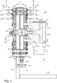
- FIG. 3a shows the inventive coupling 130 in side view and FIG. 4 in longitudinal section along the line AA.
- the inventive clutch 130 comprises a first clutch disc 135 and a second clutch disc 136, which are preferably arranged concentrically to one another.
- the clutch discs 136 is round or even circular.
- the second clutch disc 136 is rotatably supported relative to the first clutch disc 135.
- the double arrow 130.1 indicates this.
- a drive 134 is provided in order to rotate the second clutch disc 136.
- the second clutch disc 136 can be moved translationally in the axial direction relative to the first clutch disc 135.
- the double arrow 130.2 on the clutch disc 136 indicates this.
- a drive 133 is provided.
- the drive 133 may include a pneumatic cylinder 133.1. Inside the pneumatic cylinder 133.1 is a piston 133.2, which can be brought with compressed air in a first position and in a second position.
- the drive 133 has for this purpose two compressed-air connections 133.3 and 133.4.
- the two compressed-air connections 133.3 and 133.4 can be connected via a respective valve V2 or V3 to a compressed air source (see FIG. 4 ).
- a respective valve V2 or V3 to a compressed air source (see FIG. 4 ).
- the valve V3 When the valve V3 is closed and the valve V2 is opened, the compressed air flows from the left into the cylinder 133.1 and pushes the piston 133.2 to the right.
- the piston 133.2 is shown in the right end position.
- the valve V2 is closed and the valve V3 is opened, the compressed air flows from the right into the cylinder 133.1 and pushes the piston 133.2 to the left.
- the piston 133.2 is positively connected via a pin 133.5 with an axis 138.
- the axis 138 may have a corresponding receptacle for this purpose.
- the axis 138 is rigidly connected to the first clutch disc 135, for example screwed.
- the second clutch disc 136 is rotatably mounted on the axle 138 by means of a bearing 138.4.
- the cylinder 133.1 is rigidly connected via connecting rods 133.6 with the second clutch disc 136.
- the first clutch plate 135 may be equipped with, for example, two bushings 135.4 and 135.5
- the second clutch plate 136 may be equipped with a positioning pin 136.2 which fits into the bushings 135.4, 135.5.
- the positioning pin 136.2 may be screwed into the clutch disc 136.
- the positioning pin 136.2 is pulled out of the corresponding sleeve 135.4 or 135.5.
- the piston 133.2 is pushed to the right by means of compressed air, the two clutch discs 135 and 136 are pushed together again and pressed against one another.
- the positioning pin 136.2 is inserted again into the corresponding socket 135.4 or 135.5, so that the two clutch discs 135 and 136 are positioned exactly to each other.
- the positioning pin 136.2 is inserted into socket 135.4, the clutch disc 136 is in the first rotational position. If the positioning pin 136.2, however, plugged into socket 135.5, the clutch disc 136 is in the second rotational position.
- drive 134 may include a pneumatic cylinder 134.1.
- the drive 134 may be attached to a bracket 135.2.
- the holder 135.2 and the first clutch disc 135 can be realized as separable components and the clutch disc 135 can be mounted on the bracket 135.2.
- the clutch disc 135 and the bracket 135.2 may also be a component.
- the clutch disc 135 may, as in FIG. 1 shown to be partially round.
- the clutch 130 may be equipped with adjustable feet 139. Inside the pneumatic cylinder 134.1 is a piston with a piston rod 134.2, the compressed air in a first Position and can be placed in a second position.
- the drive 134 has for this purpose two compressed-air connections 134.3 and 134.4.
- the two compressed-air connections 134.3 and 134.4 can be connected via a respective valve V4 or V5 to a source of compressed air (see FIG. 1 ).
- a source of compressed air see FIG. 1 .
- the valve V4 When the valve V4 is closed and the valve V5 is opened, the piston is pushed into the cylinder 134.1 or the piston rod 134.2 is pulled into the cylinder.
- the valve V5 When the valve V5 is closed and the valve V4 is opened, the compressed air pushes the piston with the piston rod 134.2 out of the cylinder 134.1.
- the piston rod 134.2 is connected via a hinge 134.5 with the second clutch disc 136.
- the clutch disc 136 rotates correspondingly.
- the angle of rotation ⁇ about which the clutch disc 136 rotates, depends on the stroke of the cylinder 134.1. If, with the aid of compressed air, the piston with the piston rod 134.2 is retracted back into the cylinder 134.1, the clutch disk 136 rotates back to its original position by the angle of rotation ⁇ .
- the axle bearing or bearing 138.4 can, as in FIG. 4 shown, for example, have the form of a socket. Preferably, it is equipped with an air purge.
- the supply of the bearing 138.4 with air for rinsing can take place via the axis 138.
- the axis 138 has a compressed air connection 138.1, to which an axially extending air duct 138.2 and at the end of the air duct 138.2 a radially extending air duct 138.3 connect.
- compressed air can flow into the two air channels 138.2 and 138.3. After the air has reached the outer end of the radially extending air channel 138.3, it flows between the axis 138 and the bearing 138.4 along and removes any powder deposited there.
- the two clutch plates 135 and 136 are preferably coaxial, that is arranged on the same axis 138.
- the axis 138 is for the clutch disc 135 whose bearing axis and for the clutch disc 136 whose axis of rotation.
- the first clutch plate 135 may include a series of conduit ports 131.
- the series of line connections 131 is also referred to below as the first group of line connections 131. If the line connections 131 are to be connected to a compressed air line 83, they may be designed as compressed air connections 183.1 to 183.n. If the line connections 131 are to be connected to powder lines 81.1, 82.2,... 82.n, they can be designed as hose nozzles 131.1, 131.2,... 131.n, where n stands for any number of line connections or lines.
- the second clutch plate 136 may have a number of line connections 132.
- the series of line connections 132 is also referred to below as the second group of line connections 132.
- the line connections 132 to compressed air lines 84 they can be designed as compressed air connections 184.1 to 184.n. If the line connections 132 are to be connected to powder lines 82.1, 82.2,... 82.n, they can be designed as hose nozzles 132.1, 132.2,.
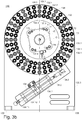
- the line connections 131 of the first coupling disk 135 can be distributed on a first pitch circle T1 with a radius r1 and on a second pitch circle T2 with a radius r2 (see FIG FIG. 3a ). The same applies mutatis mutandis to the line connections 132 of the second clutch disc 136.
- a total of 52 line connections 131 and, on the second coupling disk 136, a total of 52 line connections 132 are provided on the first coupling write 135.
- On the first pitch circle T1 are 26 of the line connections 132. 26 more of the line connections 132 are located on the second pitch circle T2.
- the lead terminals 131 are preferably arranged in the same manner as the lead terminals 132.
- the two pitch circles T1 and T2 are preferably arranged concentrically.
- the line terminal 184.1 is connected to the line terminal 183.1. Furthermore, the line connection 184.2 is connected to the line connection 183.2, the line connection 132.1 to the line connection 131.1 and the line connection 132.2 to the line connection 131.2. The same applies mutatis mutandis to the remaining line connections 184.3 ... 184.n, 132.3 ... 132.n, 183.3 ... 183.n and 131.3 ... 131.n. With the Clutch 130 can thus be connected to each other via a located in the clutch plates channel two of the line connections.
- first clutch disc 135 In the first clutch disc 135 are on the first pitch circle T1 26 axially extending channels 135.1. On the second pitch circle T2 there are 26 further axially extending channels 135.1. Each of the channels 135.1 is assigned to one of the line connections 131.
- the second clutch disc 136 is the same structure in this regard. Thus, on the second clutch disc 136 on the first pitch circle 26 axially extending channels 136.1. On the second pitch circle T2 are 26 more axially extending channels 136.1. Each of the channels 136.1 is associated with one of the line terminals 132.
- the channels 135.1 of the first clutch plate 135 and the channels 136.1 of the second clutch plate 136 are connected to each other in pairs.
- the transition from a channel 135.1 to the adjoining channel 136.1 is preferably equipped with a seal 137. This applies to all transitions between two channels 135.1 and 136.1.
- the seals 137 are preferably in the form of a sleeve.
- Spacers 135.3 may be provided between the two clutch plates 135 and 136. These may for example be attached to the clutch disc 135 (see FIG. 1 ).
- the clutch disc 135 may have threaded holes to which spacers 135.3 are screwed. When the two clutch plates 135 and 136 are pressed together (see, for example FIG. 4 ), the spacers 135.3 between the two clutch plates 135 and 136 ensure that the seals 137 are not compressed too tightly and damaged.
- powder is conveyed through the powder line 81.1, it passes via the port 131.1, the corresponding channel 135.1 of the clutch disc 135, the corresponding channel 136.1 of the clutch disc 136 and the port 132.1 in the powder line 82.1.
- powder is conveyed via the powder line 81.2, it passes via the port 131.2 and the corresponding channel 135.1 of the clutch disc 135, the corresponding channel 136.1 of the clutch disc 136 and the port 132.2 in the powder line 82.2.
- the clutch 130 operates as follows. In a first step, the second clutch sprocket 136 is spaced by ⁇ x from the first clutch sprocket 135 by means of the drive 133 and the positioning pin 136.2 is pulled out of the one bush 135.4, for example. In a second step, the clutch write 136 is rotated by the rotational angle ⁇ from a first rotational position to a second rotational position. For this purpose, the piston rod 134.2 is pushed out of the cylinder 134.1. Subsequently, the second clutch disc 136 is again brought to the first clutch disc 135 and pressed by means of the drive 133. The positioning pin 136.2 is now inserted into the other socket 135.5.
- the positioning pin 136.2 and the bushes 135.4 and 135.5 help to position the adjacent channels 135.1 and 136.1 exactly to one another, so that at the transition between the adjacent channels 135.1 and 136.1 and the seals 137th no dead space is created and therefore no powder can be deposited there.
- the powder lines 82 can be freed from the powder with compressed air.
- the valve V11 is opened, so that compressed air via the line 83, the port 183.1, the corresponding channel 135.1 of the clutch disc 135, the corresponding channel 136.1 of the clutch disc 136 and the port 132.1 flows into the powder line 82.1 and the powder located there in the direction of Pulverapplikator 80 is transported out of the line 82.1.
- the second clutch disc 136 is moved away from the first clutch disc 135. Then, the clutch disc 136 is rotated back to the original rotational position, moved back to the first clutch disc 135 and to this pressed. The powder lines are then available again for the powder coating operation.
- the terminals 131 and 132 of the first and second clutch plates 135 and 136 can be arbitrarily occupied.
- the lines 83 may be formed, for example, instead of compressed air lines as further powder lines.
- powders of a first color may be transported in the powder lines 81, and powders of a second color may be transported in the lines 83.
- the clutch disc 136 By rotating the clutch disc 136, the pairings of the terminals 131 and 132 can be changed quickly, so that a quick and easy color change can be made between the first and second colors.
- the clutch disc 136 can also be gradually rotated by a multiple of the rotational angle ⁇ , so that more than two rotational positions can be approached.
- the embodiment shown is an example of this. In this way, for example, even more colors can be added, between which can then be changed quickly and easily in the manner described above.
- the clutch disc 136 can assume three different rotational positions: For example, in the first position the angle of rotation is 0 °, in the second position the angle of rotation is ⁇ and in the third position the angle of rotation is 2 * ⁇ . This could be in the first position with powder a first color to be transported. In the second position, the powder-carrying lines can be cleaned with compressed air. In the first third position powder can be transported with a second color.
- the clutch disc 136 can assume three different rotational positions, is in the in FIG. 3b shown embodiment, a drive 134 with two pneumatic cylinders 134.1 and 134.10 available.
- the two pneumatic cylinders 134.1 and 134.10 are arranged one behind the other.
- the piston rod 134.11 of the pneumatic cylinder 134.10 is supported on the bracket 135.2.
- the piston rod 134.2 of the pneumatic cylinder 134.1 is connected via the joint 134.5 with the second clutch disc 136.
- the pneumatic cylinder 134.1 and thus the clutch disc 136 can be brought into a first and a second position.
- the clutch disc 136 can be brought into the third position. If the pistons 134.2 and 134.11 of the two pneumatic cylinders 134.1 and 134.10 retracted, the clutch disc 136 is in its first rotational position.
- the clutch disc 136 can be brought into the second rotational position by the piston rod 134.2 of the pneumatic cylinder 134.1 or the piston rod 134.11 of the pneumatic cylinder 134.10 is extended.
- both the piston rod 134.2 of the pneumatic cylinder 134.1 and the piston rod 134.11 of the pneumatic cylinder 134.10 are extended.
- the number of terminals 131 and 132 and the number of pitch circles can be changed and adapted to the respective needs.
- FIG. 3b shown embodiment of the clutch 130 on the first and the second clutch disc 135 and 136 each have three pitch circles T1, T2 and T3 with the radii r1, r2 and r3 present.
- the coupling 130 according to FIG. 3b has per line 36 line connections 135 and 136, respectively.
- the powder center 1 which is also referred to as a powder supply device, powder center or integrated powder management system, comprises a powder reservoir 3 which serves to store the coating powder.
- the powder center 1 comprises a powder conveying device 1.1, with which the powder is conveyed out of the powder storage container 3 and transported to a powder applicator 80.
- the powder conveying device 1.1 is integrated in the present case in the powder reservoir 3 and will be explained later in more detail.
- the powder applicator 80 (see FIG. 5 ) may be formed as a manual or automatic Pulversprühvorraum and has at its outlet to the workpiece 65 towards a spray nozzle or a rotary atomizer.
- the powder center 1 is constructed as a module. As a result, the powder center 1 can be transported quickly and easily as a compact unit.
- the individual components of the powder center 1 are attached to frame profiles 2, which may be made of aluminum or steel, for example.
- the Frame profiles 2 form the outer boundary of the powder center 1. If necessary, the powder center 1 may have a bottom 7.
- the powder reservoir 3 of the powder center 1 can be arranged for example on a base 6. Like in FIG. 11 can be completed with a powder container lid 23 during the conveying operation of the powder reservoir 3.
- the powder container lid 23 has the shape of an inverted pot.
- the powder reservoir 3 has for this purpose seals and locking receptacles 3.1, can engage in the correspondingly formed counterparts of the pneumatic latch 18.
- the pneumatic lock 18 may for example be equipped with a cylinder, a piston and a piston rod. When the lower chamber of the cylinder is pressurized with compressed air, the piston and thus the piston rod are pushed upwards.
- the claw located at the lower end of the piston rod engages in the locking receptacle 3.1 and causes the powder container lid 23 is pressed onto the powder reservoir 3.
- there are three such latches 18 (for example, in FIGS FIGS. 8 and 9 shown). The number of latches 18 and their structure can be readily adapted to the particular needs.
- a sieve 24 which may be formed as an ultrasonic sieve.
- the ultrasonic transducer 24.1 of the sieve 24 is preferably located outside of the powder reservoir 3.
- the sieve 24 is accessible and can be removed.
- the ultrasound screen 24 is attached to a pivoting mechanism 16 via a support arm 22.
- the screen 24 can by means of the pivoting mechanism 16 from the working position (see FIG. 8 ) and brought to a cleaning position in a cleaning station 27 (see FIG. 14 ).
- the cleaning station 27 is also referred to below as a screen cleaning device or screen cleaning station.
- the cleaning station 27 also includes a lid 15 which can be opened and closed, for example, by means of a pneumatic cylinder 17.
- the lid 15 is pivoted about a hinge 21.
- a curved double arrow indicates the pivoting movement.
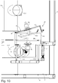
- On the underside of the lid 15 carries a cleaning arm 19, which is also equipped with a plurality of cleaning nozzles 19.1.
- the cleaning nozzles 19.1 are preferably located on the underside of the cleaning arm 19. They are aligned so that during the cleaning operation, they blow compressed air down onto the ultrasonic sieve 24 located below the cleaning arm 19.
- the upper cleaning arm 19 is rotatably mounted with a bearing 50 on the lid 15.
- the lower cleaning arm 20 is rotatably supported by a bearing 51 on the cleaning container 14.
- the two bearings 50 and 51 may also be designed as air motors.
- the direction of rotation of the upper cleaning arm 19 and the direction of rotation of the lower cleaning arm 20 is indicated by an arrow.
- the sense of rotation of the cleaning arm results from the staggered arrangement of the cleaning nozzles and the recoil, which occurs when compressed air flows through the nozzles.
- the ultrasonic sieve 24 is located between the lower cleaning arm 20 and the upper cleaning arm 19.
- the cleaning arm 19 may be provided at both ends (as in FIG FIG. 10 shown) so that it has a horizontal leg and two obliquely upwardly directed legs.
- the compressed-air nozzles 19.1 can be located both on the horizontal leg and on the obliquely upwardly directed legs.
- the cleaning arm 19 may be formed as a tube to guide the compressed air inside the tube to the compressed air nozzles 19.1. Analogously, the same applies to the lower cleaning arm 20, even if in FIG. 10 the ends of the lower cleaning arm 20 are not angled.
- a lower container portion 14.2 On the underside of the container 14 for receiving the sieve 24 is a lower container portion 14.2 with an outlet 14.1. About the outlet 14.1 located in the cleaning station 27 powder-air mixture can be sucked.
- the outlet 14.1 is connected via a hose, not shown in the figures, to an inlet opening 13.2 of a suction tube 13.
- the powder-air mixture can be sucked via the suction tube 13 and a suction 91 in a secondary filter 100.
- the powder inlet of the working container 3, 23 is preferably located in its upper region. It may, for example, be arranged in the powder container lid 23 of the working container 3, 23.
- the working container 3, 23 may also have a plurality of powder drains.
- the powder inlet 23.1 is connected to the powder outlet 4.2 of an intermediate container 4 via a powder valve M21, which is designed, for example, as a pneumatically controlled squeeze.
- the intermediate container 4 serves together with the inlet valve M20 and the outlet valve M21 as a powder conveyor 4 and is usually arranged above the working container 3, 23. In this way, the gravity can be exploited to transport powder located in the intermediate container 4 down into the working container 3, 23.
- a second powder conveyor 5 may be arranged above the working container 3, 23. Its powder outlet also opens into the working container 3, 23.
- the second powder conveyor 5 may be constructed as the first powder conveyor 4.
- the powder conveying device 1.1 integrated into the powder reservoir 3 will be explained in more detail below.
- the powder conveying device can, as in the European patent application EP 3 238 832 A1 described, be trained.
- the working container 3, 23 is designed and operable so that it can be placed under pressure. With the aid of the powder conveyor 4, powder can be conveyed out of the fresh powder station 30 and transported into the working container 3, 23.
- the working container 3, 23 has in the region of the container bottom 25 a fluidizing insert 25.1 for fluidizing the powder and a series of powder outlets 3.2. It may be provided that a powder outlet valve G1-G36 is connected to each of the powder outlets 3.2.
- a powder line 81 is connected to each of the powder outlet valves G1-G36.
- Each of the powder lines 81 (81.1... 81.n) also has an inlet for transport air on the input side, that is to say in the vicinity of the respective powder outlet valve G1-G36.
- each of the powder lines 81 is preferably connected to one of the powder applicators 80 via the above-described coupling 130 and the powder lines 82 (82.1... 82.n).
- the amount of powder to be conveyed is controlled by repeatedly opening and closing the respective powder outlet valve G1-G36 by means of a controller 70.
- the above-referenced patent application EP 3 238 832 A1 referred, the content of which is hereby part of the present application.
- a vibrator 220 is provided, which may be located below the powder reservoir 3, for example (see FIG. 11 ). With the help of the shaker movements generated by the vibrator 220, the powder-air mixture in the powder reservoir 3 can be evenly fluidized. In addition, the powder-air mixture can thereby flow out of the powder outlet channel 203 more optimally.
- the clutch 130 has on the one clutch disc 135, the first group of terminals 131 and on the other Clutch disc 136, the second group of terminals 132 on.
- the controller 70 is adjustable, which terminal of the first group 131 is connected to which terminal of the second group 132.
- one of the powder lines 81 can be connected on the output side to a respective connection of the first group 131.
- one connection of the second group 132 can be connected in each case a powder line 82, which is on the other hand connected to one of the powder applicators 80.
- 36 powder outlet valves G1-G36 are used. However, more or less many powder outlet valves can be used. The number of powder outlet valves used depends on the number of powder applicators 80 used.
- a powder injector operating on the venturi principle or a powder pump for dense phase conveying may also be provided.
- the powder conveyor 4 may also be provided a powder pump for dense phase conveying, a peristaltic pump or a Pulverinjektor. The same applies analogously to the powder conveyor 5.
- the powder reservoir 3 and the powder container lid 23 and the two powder conveyors 4 and 5 are attached to a vertical linear axis 12, and can thus be moved up and down.
- the drive 12.1 of the linear axis 12 can be located at the top of the linear axis 12.
- the vertical double arrow in FIG. 11 indicates its direction of movement.
- the powder center 1 next to it comprises a container cleaning unit 28 or, in short, a cleaning unit comprising a cleaning container 10, an upper cleaning arm 11 and a lower cleaning arm 26.
- the upper cleaning arm 11 and the lower cleaning arm 26 are rotatably mounted in the cleaning container 10 and each have a plurality of operated with compressed air cleaning nozzles 11.1 and 26.1.
- the cleaning container 10 is attached to a linear drive 9 and can be moved with this vertically up and down (in the y direction).
- the vertical double arrow in FIG. 11 indicates its direction of movement.
- the drive 9.1 of the linear drive 9 can be located at the top of the linear drive 9.
- the linear drive 9 in turn is fastened to a horizontally oriented linear drive 8 (also called a linear axis) and can be moved back and forth with it horizontally (in the x-direction).
- the drive 8.1 of the linear axis 8 can be arranged laterally on the linear axis 8.
- the container cleaning unit 28 With the linear axis 8, it is possible to position the container cleaning unit 28 laterally next to the working container 3, 23 during the conveying operation (see FIG FIGS. 6 to 9 ).
- the container lid 23 is moved upwards; then the container cleaning unit 28 can be positioned by means of the two linear actuators 8 and 9 so that the cleaning container 10 is first brought over the powder reservoir 3 and then lowered so far, so that the cleaning arm 26 a defined distance from the bottom 25 of the powder reservoir. 3 having.
- the outstanding below from the cleaning tank 10 cleaning arm 26 is then inside the powder reservoir 3 and serves to clean the inner wall and the bottom 25 of the powder reservoir.
- the powder container lid 23 can be lowered so far that the inner surfaces of the powder container lid 23 can be blown off and thus cleaned with the cleaning arm 11 protruding from the cleaning container 10 above.
- the cleaning arm 11 protrudes into the interior of the powder container lid 23.
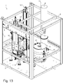
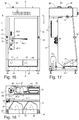
- FIGS. 15 to 18 shown in different views.
- the fresh powder station 30 can be designed, for example, as an independent module.
- the station comprises a first footprint 31 and a second footprint 32, each comprising a powder carton 110, 111 (see FIG. 5 ) be able to record.
- the two shelves 31 and 32 are preferably arranged obliquely, so that the powder moves with the aid of gravity in the powder carton obliquely down into a corner.
- the powder box can be emptied easily or almost completely with the help of a suction lance 33 without much effort.
- the suction lance 33 is, as in the FIGS.
- the fresh powder station 30 has an additional linear drive 38 in order to be able to move the suction lance 33 also vertically.
- the vibrator 54 serves to put the powder in the carton 110 in motion so that it spreads better and flows in the direction of the suction lance 33.
- the level in the box 110 can be determined, and if the level falls below a certain level, a change of the powder cartons are initiated. In addition, it can be detected via the measuring signal generated by the balance 46 whether there is still enough space in the carton 110 when powder is to be conveyed via the line 96 from the powder center 1 back to the powder station 30.
- the fresh powder station 30 additionally has a cleaning station 52, which is equipped with a scraper ring and / or compressed air nozzles and / or an exhaust.
- a cleaning station 52 which is equipped with a scraper ring and / or compressed air nozzles and / or an exhaust.
- air nozzles 57 may be attached to the cleaning station 53 to clean the lower portion of the suction lance 33. If the suction lance 33 has a fluidizing crown to fluidize the powder in the suction area, this can also be cleaned with it.
- a powder container 150 could be installed with a fluidizing.
- powder can be conveyed via a respective powder line 127 from a BigBag 121 into the powder container 150.
- a BigBag 120 with a pump 123 may also be provided.
- the powder can be pumped by the pump 123 via a powder line 126 directly to the powder conveyor 4.
- the BigBag 120 or 121 is also referred to as Flexible Intermediate Bulk Container or short FIBC. It usually contains larger amounts of powder than the powder carton 110 and the powder carton 111. Also, the BigBag 120/121 is usually further away from the powder conveyor 4 than the powder carton 110 or 111. Thus, the BigBag 120/121 at a distance from the Example 30m to the powder conveyor 4, whereas the powder carton 110 or 111, for example, 5 m away from the powder conveyor 4.
- the fresh powder station 30 may include a plurality of compressed air control valves 39 and 40 and knobs 41 and 42.
- the compressed air control valve 39 may be provided for adjusting the fluid air of the fluid tray of the powder container 150.
- the compressed air control valve 40 is used to adjust the fluid air at the fluidizing crown of the suction lance 33. With the help of the adjusting knob 41, the position of the exhaust air flap can be controlled. About the knob 42 a confirmation signal can be transmitted to the controller.
- the fresh powder station 30 can have an exhaust 37 with a suction opening 37.1 in order to be able to extract excess powder from the interior of the fresh powder station 30.
- the fresh powder station 30 may also have a flexible suction hose that can be manually cleaned when needed.
- the fresh powder station 30 has a pivot mechanism 45 for the powder conveyor 49.
- the pivot mechanism 45 has a drive, which may be formed, for example, as a pneumatic drive, and a pivot arm 45.1.
- the powder conveyor 49 (see FIG. 15 ) are brought from the conveying position to a cleaning position. In the cleaning position, the powder conveyor 49 protrudes into the interior of the fresh powder station 30.
- air nozzles 56 may be provided to clean the lower portion of the powder conveyor 49 when it is pivoted from the conveying position to the cleaning position or from the cleaning position to the conveying position.
- the pneumatic drive may comprise two pneumatically driven cylinders.
- the powder conveyor 49 can thus be brought into a cleaning position, a first conveying position and a second conveying position. To move the powder conveyor 49 to the cleaning position (see Fig. 15 ), the cylinder 1 and the cylinder 2 are retracted. In the first conveying position, the powder conveyor 49 is located above the footprint 31. For this purpose, the Cylinder 1 retracted and cylinder 2 extended. In the second conveying position, the powder conveyor 49 is located above the footprint 32; the cylinders 1 and 2 are extended. In the first conveying position, powder may be fed back into the powder carton 110, and in the second conveying position, powder may be conveyed back into the powder carton 111.
- the suction lance 33 can be brought with the linear axis 38 and the linear drive 44 in three different positions: In the cleaning position (see Fig. 15 ) is the suction lance 33 in the cleaning station 53. In the first conveying position, the suction lance 33 is located above the footprint 31 and in the second conveying position on the footprint 32nd
- the fresh powder station 30 can also be equipped with its own control 43.
- this controller 43 for example, the suction lance 33, the cleaning station 52 for the suction lance 33, the linear axis 38, the linear actuator 44, the pivot mechanism 45 and the tuyeres 56 and 57 can be controlled.
- powder conveyor 49 is advantageously positioned directly above that of the powder carton 110 and 111, in which he is to promote powder back. Since it uses gravity, the powder drops after the outlet valve 49. 2 of the powder conveyor 49 is opened, into the powder carton below the powder conveyor 49.
- the powder conveyor 49 serving to return the powder may also be designed differently. It can be designed, for example, as a powder pump. Since gravity is not utilized in such a powder pump, it may be located at various locations. For example, it may also be at the same height as the powder carton 110.
- two covers 35 and 36 may be provided, which can be opened manually.
- the staff has access to the interior of the fresh powder station 30 from above.
- the fresh powder station 30 may also be equipped with side walls 34 and a rear wall 48.
- FIG. 5 A possible embodiment of an entire plant for powder coating of workpieces 65 is shown in FIG. 5 simplified as a block diagram.
- the entire system can be controlled via a central controller 70.
- the controller 70 may be connected and provided to various components of the entire plant via corresponding control lines (not shown in the figures), the powder coating booth 60 including powder applicators 80, the fresh powder station 30, the powder center 1, the powder recovery 90 and / or the postfilter 100 to control.
- the fresh powder station 30 may have a separate controller 43.
- the excess powder which is also referred to as overspray, must be removed from the booth 60 again. This is necessary on the one hand because the environment outside the cabin is to be kept free of powder dust. On the other hand, the danger of explosion when exceeding a certain powder concentration by the powder dust cloud floating in the cabin increases. This should be avoided.
- the resulting in the coating overspray is sucked together with the air in the cabin 60 as a powder-air mixture from the cabin 60 and fed via a residual powder pipe 92 a device for powder recovery 90.
- the powder recovery device 90 may be formed, for example, as a cyclone. If necessary, the powder recovered there can be returned to the powder center 1 via a powder line 94. In order to filter out also the proportion of the powder, which he was not filtered out in the cyclone 90, the powder-air mixture can be supplied from the cyclone via a suction line 93 to the post-filter 100.
- the powder-air mixture in the residual powder piping 92 is also referred to as residual powder air flow.
- the cab 60 has a suction slot. It connects the interior of the cabin 60 with the residual powder piping 92. Over the suction slot and the suction pipe 61 is thus excess powder as a powder-air mixture from the The inside of the cabin is sucked off and supplied to a cyclone separator 90 or, in short, a cyclone, which may be designed as a monocyclone.
- the powder-air mixture flows tangentially into the cyclone 90 and in the cyclone down spiral.
- the powder particles are pressed by the centrifugal force arising during the rotation of the powder air flow to the outside of the outer wall of the cyclone 90 to the outside.
- the powder particles are conveyed downwards in the direction of the powder outlet of the cyclone and collected there.
- the freed of the powder particles air is sucked off via the vertical central tube located in the cyclone 90.
- the air stream cleaned in this way is often fed to a secondary filter 100 in order to filter out even the residual powder remaining in the air.
- the recovered powder in the cyclone 90 can be used again for coating and fed to the powder center 1 via the powder line 94.
- the ultrasonic sieve 24 is located in the working container 3, 23 between the powder reservoir 3 and the powder container lid 23.
- the latches 18 ensure that the working container is hermetically sealed.
- the screen cleaning device 27 and the container cleaning unit 28 are as shown in FIGS FIGS. 6 to 8 shown in the park position.
- the parking position for the container cleaning unit 28 is located next to the powder reservoir 3.
- the phrase "next to the powder reservoir” also includes above, below, in front of or behind the powder reservoir.
- the sieve 24 is not absolutely necessary.
- the powder delivery can also be done without ultrasonic sieve or entirely without sieve 24.
- the powder delivery from the powder storage container 3 is set and the residual powder still remaining in the powder storage container 3 is suctioned off with the powder conveyor 49 via the outlet 25.1 and the line 96.
- the material valve M11 is opened to the purge valve S12 is closed during this time.
- the still prevailing in the working container 3, 23 overpressure is reduced to atmospheric pressure and the latches 18 are opened.
- the powder container lid 23 is raised by means of the linear drive 12 and the ultrasonic sieve 24 is pivoted by means of the pivot mechanism 16 from the working position to the cleaning position.
- the linear actuator 12 raises the container lid 23 so far that the cleaning container 10 can be driven by means of the two linear axes 8 and 9 between the powder container lid 23 and the powder reservoir 3. Subsequently, the container cleaning unit 28 is lowered with the cleaning container 10 until the lower cleaning arm 26 is located in the interior of the powder reservoir 3 and has a defined distance to the bottom 25 of the powder reservoir 3.
- the powder container lid 23 is now lowered until the upper cleaning arm 11 is located inside the powder container lid 23 and has a defined distance from the powder container lid 23.
- an air gap remains between the powder container lid 23 and the cleaning container 10. Also between the powder container 3 and the cleaning container 10 remains an air gap. From the afterfilter 100, air is sucked in via the air gaps. This prevents that the powder-air mixture generated during the cleaning process by the compressed air nozzles 11.1 and 26.1 can escape to the environment.
- the units of powder container lid 23, cleaning container 10 and powder reservoir 3 can be sealed airtight with the latches 18.
- compressed air is blown through the nozzles 11.1 and 26.1 in the direction of the inner walls of the powder container lid 23 and the powder reservoir 3.
- the resulting powder-air mixture is sucked off via the suction line 13 and can be fed to the cyclone 90 and / or the post-filter 100.
- the lid 15 is closed by means of the pneumatic cylinder 17. Between the lid 15 and the cleaning container 14 may remain an air gap. In another embodiment, the lid 15 can also be placed airtight on the cleaning container 14.
- the blowing off of the strainer is stopped. If the powder container 3 and the container lid 23 are clean, the blowing off is stopped here as well.
- the latches 18 have been previously closed, they will now be reopened.
- the container lid 23 is raised and the container cleaning unit 28 is moved back into the parking position (see FIGS. 6 to 9 ). Also, the lid 15 is raised. After the cleaning mode is completed, the screen 23 is moved back to its working position. Subsequently, it can be started again with the conveying of powder.
- the following purification steps can be performed.
- the steps are preferably performed automatically and coordinated by the controller 70.
- the powder reservoir 3 and the container lid 23 are cleaned as described above.
- a change to another coating powder is carried out.
- the other coating powder may be that powder with which the workpieces 65 are to be coated next. But this is not absolutely necessary. Instead, you can also switch to a special cleaning agent.
- the cleaning agent may, for example, be a granulate having a particle size between 2 mm and 7 mm.
- the grain size, the grain material and the grain texture are preferably selected so that they can be promoted on the one hand through all openings in the powder system, and on the other hand have a good cleaning effect.
- care is also taken to ensure that no additional wear occurs in the powder system and no chemical incompatibility with the coating powder.
- an additional step is switched for a limited duration in the conveying mode, so that the other coating powder or the cleaning agent flows through the individual components of the system.
- the short production operation for example, with 3 kg of powder can be driven to loss.
- the material the powder or the cleaning agent
- the powder lines 91, 92, 93 and 94 can be rinsed with the new material. This is especially true of Advantage when using the new powder for recovery.
Landscapes
- Life Sciences & Earth Sciences (AREA)
- Engineering & Computer Science (AREA)
- Wood Science & Technology (AREA)
- Coating Apparatus (AREA)
Priority Applications (4)
| Application Number | Priority Date | Filing Date | Title |
|---|---|---|---|
| PL18167080T PL3552715T3 (pl) | 2018-04-12 | 2018-04-12 | Instalacja powlekania proszkowego ze sprzęgłem i sposób czyszczenia instalacji powlekania proszkowego |
| EP18167080.3A EP3552715B1 (fr) | 2018-04-12 | 2018-04-12 | Installation de revêtement par poudre pourvue d'accouplement et procédé de nettoyage du système de revêtement par poudre |
| US16/377,214 US11020762B2 (en) | 2018-04-12 | 2019-04-07 | Coupling for the connecting of lines, powder coating facility including the coupling, and method for cleaning of the powder coating facility |
| CN201910288062.XA CN110369173B (zh) | 2018-04-12 | 2019-04-11 | 粉末涂覆设备及其清洁方法 |
Applications Claiming Priority (1)
| Application Number | Priority Date | Filing Date | Title |
|---|---|---|---|
| EP18167080.3A EP3552715B1 (fr) | 2018-04-12 | 2018-04-12 | Installation de revêtement par poudre pourvue d'accouplement et procédé de nettoyage du système de revêtement par poudre |
Publications (2)
| Publication Number | Publication Date |
|---|---|
| EP3552715A1 true EP3552715A1 (fr) | 2019-10-16 |
| EP3552715B1 EP3552715B1 (fr) | 2021-02-17 |
Family
ID=61972387
Family Applications (1)
| Application Number | Title | Priority Date | Filing Date |
|---|---|---|---|
| EP18167080.3A Active EP3552715B1 (fr) | 2018-04-12 | 2018-04-12 | Installation de revêtement par poudre pourvue d'accouplement et procédé de nettoyage du système de revêtement par poudre |
Country Status (4)
| Country | Link |
|---|---|
| US (1) | US11020762B2 (fr) |
| EP (1) | EP3552715B1 (fr) |
| CN (1) | CN110369173B (fr) |
| PL (1) | PL3552715T3 (fr) |
Families Citing this family (5)
| Publication number | Priority date | Publication date | Assignee | Title |
|---|---|---|---|---|
| KR102649715B1 (ko) * | 2020-10-30 | 2024-03-21 | 세메스 주식회사 | 표면 처리 장치 및 표면 처리 방법 |
| US11465169B1 (en) * | 2021-03-24 | 2022-10-11 | Royce Metal Products Limited | Apparatus for coating or mixing items with controlled unloading |
| CN114308435B (zh) * | 2022-03-08 | 2022-05-27 | 季华实验室 | 喷涂送粉装置 |
| WO2025146244A1 (fr) * | 2024-01-02 | 2025-07-10 | Abb Schweiz Ag | Changeur de couleur, appareil d'alimentation en peinture et système d'alimentation en peinture |
| CN118594828B (zh) * | 2024-08-06 | 2024-10-29 | 成都大信智慧交通科技有限公司 | 一种损伤波形栏护板的表面雾化补塑喷头及喷塑装置 |
Citations (5)
| Publication number | Priority date | Publication date | Assignee | Title |
|---|---|---|---|---|
| US6705545B1 (en) * | 1998-11-13 | 2004-03-16 | Steelcase Development Corporation | Quick color change powder paint system |
| EP2361691A1 (fr) | 2010-02-19 | 2011-08-31 | Ramseier Koatings Technologies AG | Sélecteur pour fluides |
| DE102015102332A1 (de) * | 2014-02-18 | 2015-08-20 | Apson Lackiertechnik Gmbh | Farbwechselsystem |
| EP3238832A1 (fr) | 2016-04-29 | 2017-11-01 | J. Wagner AG | Dispositif de transport destine a transporter de la poudre de revetement vers un applicateur de poudre, installation de revetement de poudre et procede de fonctionnement d'un dispositif de revetement de poudre |
| DE102016118395A1 (de) * | 2016-06-21 | 2017-12-21 | Apson Lackiertechnik Gmbh | Farbwechselsystem |
Family Cites Families (4)
| Publication number | Priority date | Publication date | Assignee | Title |
|---|---|---|---|---|
| CN102791383B (zh) * | 2010-01-06 | 2017-11-14 | 恩特格里斯公司 | 具有除气和感测能力的液体分配系统 |
| CN106461446A (zh) * | 2014-05-13 | 2017-02-22 | Fl史密斯公司 | 定量和清洁样品准备装置及其方法 |
| WO2016172190A1 (fr) * | 2015-04-20 | 2016-10-27 | Akron Brass Company | Dispositif de modèle amélioré de pulvérisateur de mousse |
| CN205056299U (zh) * | 2015-09-28 | 2016-03-02 | 华南理工大学 | 一种多喷枪静电粉末喷涂控制系统 |
-
2018
- 2018-04-12 EP EP18167080.3A patent/EP3552715B1/fr active Active
- 2018-04-12 PL PL18167080T patent/PL3552715T3/pl unknown
-
2019
- 2019-04-07 US US16/377,214 patent/US11020762B2/en active Active
- 2019-04-11 CN CN201910288062.XA patent/CN110369173B/zh active Active
Patent Citations (5)
| Publication number | Priority date | Publication date | Assignee | Title |
|---|---|---|---|---|
| US6705545B1 (en) * | 1998-11-13 | 2004-03-16 | Steelcase Development Corporation | Quick color change powder paint system |
| EP2361691A1 (fr) | 2010-02-19 | 2011-08-31 | Ramseier Koatings Technologies AG | Sélecteur pour fluides |
| DE102015102332A1 (de) * | 2014-02-18 | 2015-08-20 | Apson Lackiertechnik Gmbh | Farbwechselsystem |
| EP3238832A1 (fr) | 2016-04-29 | 2017-11-01 | J. Wagner AG | Dispositif de transport destine a transporter de la poudre de revetement vers un applicateur de poudre, installation de revetement de poudre et procede de fonctionnement d'un dispositif de revetement de poudre |
| DE102016118395A1 (de) * | 2016-06-21 | 2017-12-21 | Apson Lackiertechnik Gmbh | Farbwechselsystem |
Also Published As
| Publication number | Publication date |
|---|---|
| EP3552715B1 (fr) | 2021-02-17 |
| PL3552715T3 (pl) | 2021-08-30 |
| US11020762B2 (en) | 2021-06-01 |
| CN110369173B (zh) | 2022-02-18 |
| US20190314844A1 (en) | 2019-10-17 |
| CN110369173A (zh) | 2019-10-25 |
Similar Documents
| Publication | Publication Date | Title |
|---|---|---|
| EP3552715B1 (fr) | Installation de revêtement par poudre pourvue d'accouplement et procédé de nettoyage du système de revêtement par poudre | |
| DE69115689T2 (de) | Pulverbeschichtungssystem | |
| DE69435065T2 (de) | Pulverbeschichtungssystem | |
| EP3552716B1 (fr) | Dispositif de transport destiné au transport de la poudre de revêtement, centre d'alimentation en poudre pourvu d'appareil de transport et procédé de nettoyage du centre d'alimentation en poudre | |
| DE2918762C2 (de) | Vorrichtung zum Überziehen bzw. Kandieren von körnigem Gut | |
| DE4134701C2 (de) | Pulver-Sprühbeschichtungseinrichtung mit alternativ austauschbaren Filter- und Zykloneinheiten | |
| DE2363721A1 (de) | Transporteinrichtung | |
| EP0337132B1 (fr) | Dispositif pour amener des matières pulvérulentes à un dispositif de distribution | |
| DE2318772B2 (de) | Verfahren und kabine zur elektrostatischen bepulverung | |
| EP2358481A1 (fr) | Installation de mise en peinture et dispositif pour faire fonctionner une installation de mise en peinture | |
| EP3621752A1 (fr) | Remplisseuse conçue pour remplir des sacs ouverts de produits en vrac et dispositif de nettoyage | |
| DE20320735U1 (de) | Pulverbeschichtungspritzkabine mit einem Pulverabsaugsystem | |
| EP3552714B1 (fr) | Transporteur de poudre destiné à transporter le poudre de revêtement, méthode de fabriquation de transportateur et centre d'alimentation en poudre pourvu de transporteur de poudre destiné à alimenter un centre d'alimentation en poudre | |
| DE69405298T2 (de) | Vorrichtung zum Sammeln von in Müllbehältern angeliefertem Müll und zum Reinigen von entleerten Müllbehältern | |
| EP3552713B1 (fr) | Centre d'alimentation en poudre destiné à l'alimentation d'une installation de revêtement par poudre et procédé de nettoyage du centre d'alimentation en poudre | |
| DE10016552A1 (de) | Puderversorgungssystem | |
| DE3815222A1 (de) | Vorrichtung zum zufuehren eines pulverfoermigen materials zu einer versorgungseinrichtung | |
| EP3743215B1 (fr) | Centre d'alimentation en poudres multicolores conçu pour alimenter à la demande au moins un dispositif de pulvérisation de poudres en poudres de revêtement de différents types | |
| EP3743216B1 (fr) | Centre d'alimentation en poudre à plusieurs couleurs pour l'alimentation en cas de besoin d'au moins un dispositif de pulvérisation de poudre avec une poudre de revêtement de différent types | |
| DE2504212A1 (de) | Vorrichtung zum entsorgen von haus-, geschaefts- und/oder industriemuell | |
| EP0054018B2 (fr) | Reservoir de poussier de charbon pourvu d'un dispositif d'evacuation dosee, en particulier de petites quantites de poussier | |
| EP3610956B1 (fr) | Installation de peinture et procédé de peinture d'une pièce à usiner | |
| EP3743217B2 (fr) | Centre d'alimentation en poudre multicolore destiné à alimenter selon les besoins au moins un équipement d'aspersion de poudre en poudre de revêtement de types différents | |
| DE102023116934B4 (de) | Rundläuferpresse und Verfahren zum Vorreinigen des Pressengehäuses einer Rundläuferpresse | |
| DE4343443C2 (de) | Verfahren und Vorrichtung zum Dosieren von saugbaren Stoffen |
Legal Events
| Date | Code | Title | Description |
|---|---|---|---|
| PUAI | Public reference made under article 153(3) epc to a published international application that has entered the european phase |
Free format text: ORIGINAL CODE: 0009012 |
|
| STAA | Information on the status of an ep patent application or granted ep patent |
Free format text: STATUS: THE APPLICATION HAS BEEN PUBLISHED |
|
| AK | Designated contracting states |
Kind code of ref document: A1 Designated state(s): AL AT BE BG CH CY CZ DE DK EE ES FI FR GB GR HR HU IE IS IT LI LT LU LV MC MK MT NL NO PL PT RO RS SE SI SK SM TR |
|
| AX | Request for extension of the european patent |
Extension state: BA ME |
|
| STAA | Information on the status of an ep patent application or granted ep patent |
Free format text: STATUS: REQUEST FOR EXAMINATION WAS MADE |
|
| 17P | Request for examination filed |
Effective date: 20200416 |
|
| RBV | Designated contracting states (corrected) |
Designated state(s): AL AT BE BG CH CY CZ DE DK EE ES FI FR GB GR HR HU IE IS IT LI LT LU LV MC MK MT NL NO PL PT RO RS SE SI SK SM TR |
|
| GRAP | Despatch of communication of intention to grant a patent |
Free format text: ORIGINAL CODE: EPIDOSNIGR1 |
|
| STAA | Information on the status of an ep patent application or granted ep patent |
Free format text: STATUS: GRANT OF PATENT IS INTENDED |
|
| RIC1 | Information provided on ipc code assigned before grant |
Ipc: B05B 7/14 20060101AFI20200825BHEP Ipc: F16K 11/078 20060101ALN20200825BHEP Ipc: B05B 12/14 20060101ALI20200825BHEP |
|
| INTG | Intention to grant announced |
Effective date: 20200918 |
|
| GRAS | Grant fee paid |
Free format text: ORIGINAL CODE: EPIDOSNIGR3 |
|
| GRAA | (expected) grant |
Free format text: ORIGINAL CODE: 0009210 |
|
| STAA | Information on the status of an ep patent application or granted ep patent |
Free format text: STATUS: THE PATENT HAS BEEN GRANTED |
|
| AK | Designated contracting states |
Kind code of ref document: B1 Designated state(s): AL AT BE BG CH CY CZ DE DK EE ES FI FR GB GR HR HU IE IS IT LI LT LU LV MC MK MT NL NO PL PT RO RS SE SI SK SM TR |
|
| REG | Reference to a national code |
Ref country code: GB Ref legal event code: FG4D Free format text: NOT ENGLISH |
|
| REG | Reference to a national code |
Ref country code: CH Ref legal event code: EP |
|
| REG | Reference to a national code |
Ref country code: DE Ref legal event code: R096 Ref document number: 502018003867 Country of ref document: DE |
|
| REG | Reference to a national code |
Ref country code: AT Ref legal event code: REF Ref document number: 1360792 Country of ref document: AT Kind code of ref document: T Effective date: 20210315 |
|
| REG | Reference to a national code |
Ref country code: IE Ref legal event code: FG4D Free format text: LANGUAGE OF EP DOCUMENT: GERMAN |
|
| REG | Reference to a national code |
Ref country code: LT Ref legal event code: MG9D |
|
| REG | Reference to a national code |
Ref country code: NL Ref legal event code: MP Effective date: 20210217 |
|
| PG25 | Lapsed in a contracting state [announced via postgrant information from national office to epo] |
Ref country code: LT Free format text: LAPSE BECAUSE OF FAILURE TO SUBMIT A TRANSLATION OF THE DESCRIPTION OR TO PAY THE FEE WITHIN THE PRESCRIBED TIME-LIMIT Effective date: 20210217 Ref country code: NO Free format text: LAPSE BECAUSE OF FAILURE TO SUBMIT A TRANSLATION OF THE DESCRIPTION OR TO PAY THE FEE WITHIN THE PRESCRIBED TIME-LIMIT Effective date: 20210517 Ref country code: PT Free format text: LAPSE BECAUSE OF FAILURE TO SUBMIT A TRANSLATION OF THE DESCRIPTION OR TO PAY THE FEE WITHIN THE PRESCRIBED TIME-LIMIT Effective date: 20210617 Ref country code: BG Free format text: LAPSE BECAUSE OF FAILURE TO SUBMIT A TRANSLATION OF THE DESCRIPTION OR TO PAY THE FEE WITHIN THE PRESCRIBED TIME-LIMIT Effective date: 20210517 Ref country code: GR Free format text: LAPSE BECAUSE OF FAILURE TO SUBMIT A TRANSLATION OF THE DESCRIPTION OR TO PAY THE FEE WITHIN THE PRESCRIBED TIME-LIMIT Effective date: 20210518 Ref country code: FI Free format text: LAPSE BECAUSE OF FAILURE TO SUBMIT A TRANSLATION OF THE DESCRIPTION OR TO PAY THE FEE WITHIN THE PRESCRIBED TIME-LIMIT Effective date: 20210217 Ref country code: HR Free format text: LAPSE BECAUSE OF FAILURE TO SUBMIT A TRANSLATION OF THE DESCRIPTION OR TO PAY THE FEE WITHIN THE PRESCRIBED TIME-LIMIT Effective date: 20210217 |
|
| PG25 | Lapsed in a contracting state [announced via postgrant information from national office to epo] |
Ref country code: SE Free format text: LAPSE BECAUSE OF FAILURE TO SUBMIT A TRANSLATION OF THE DESCRIPTION OR TO PAY THE FEE WITHIN THE PRESCRIBED TIME-LIMIT Effective date: 20210217 Ref country code: RS Free format text: LAPSE BECAUSE OF FAILURE TO SUBMIT A TRANSLATION OF THE DESCRIPTION OR TO PAY THE FEE WITHIN THE PRESCRIBED TIME-LIMIT Effective date: 20210217 Ref country code: NL Free format text: LAPSE BECAUSE OF FAILURE TO SUBMIT A TRANSLATION OF THE DESCRIPTION OR TO PAY THE FEE WITHIN THE PRESCRIBED TIME-LIMIT Effective date: 20210217 Ref country code: LV Free format text: LAPSE BECAUSE OF FAILURE TO SUBMIT A TRANSLATION OF THE DESCRIPTION OR TO PAY THE FEE WITHIN THE PRESCRIBED TIME-LIMIT Effective date: 20210217 |
|
| PG25 | Lapsed in a contracting state [announced via postgrant information from national office to epo] |
Ref country code: IS Free format text: LAPSE BECAUSE OF FAILURE TO SUBMIT A TRANSLATION OF THE DESCRIPTION OR TO PAY THE FEE WITHIN THE PRESCRIBED TIME-LIMIT Effective date: 20210617 |
|
| PG25 | Lapsed in a contracting state [announced via postgrant information from national office to epo] |
Ref country code: SM Free format text: LAPSE BECAUSE OF FAILURE TO SUBMIT A TRANSLATION OF THE DESCRIPTION OR TO PAY THE FEE WITHIN THE PRESCRIBED TIME-LIMIT Effective date: 20210217 Ref country code: CZ Free format text: LAPSE BECAUSE OF FAILURE TO SUBMIT A TRANSLATION OF THE DESCRIPTION OR TO PAY THE FEE WITHIN THE PRESCRIBED TIME-LIMIT Effective date: 20210217 Ref country code: EE Free format text: LAPSE BECAUSE OF FAILURE TO SUBMIT A TRANSLATION OF THE DESCRIPTION OR TO PAY THE FEE WITHIN THE PRESCRIBED TIME-LIMIT Effective date: 20210217 |
|
| REG | Reference to a national code |
Ref country code: DE Ref legal event code: R097 Ref document number: 502018003867 Country of ref document: DE |
|
| PG25 | Lapsed in a contracting state [announced via postgrant information from national office to epo] |
Ref country code: MC Free format text: LAPSE BECAUSE OF FAILURE TO SUBMIT A TRANSLATION OF THE DESCRIPTION OR TO PAY THE FEE WITHIN THE PRESCRIBED TIME-LIMIT Effective date: 20210217 Ref country code: DK Free format text: LAPSE BECAUSE OF FAILURE TO SUBMIT A TRANSLATION OF THE DESCRIPTION OR TO PAY THE FEE WITHIN THE PRESCRIBED TIME-LIMIT Effective date: 20210217 Ref country code: SK Free format text: LAPSE BECAUSE OF FAILURE TO SUBMIT A TRANSLATION OF THE DESCRIPTION OR TO PAY THE FEE WITHIN THE PRESCRIBED TIME-LIMIT Effective date: 20210217 Ref country code: RO Free format text: LAPSE BECAUSE OF FAILURE TO SUBMIT A TRANSLATION OF THE DESCRIPTION OR TO PAY THE FEE WITHIN THE PRESCRIBED TIME-LIMIT Effective date: 20210217 |
|
| PLBE | No opposition filed within time limit |
Free format text: ORIGINAL CODE: 0009261 |
|
| STAA | Information on the status of an ep patent application or granted ep patent |
Free format text: STATUS: NO OPPOSITION FILED WITHIN TIME LIMIT |
|
| PG25 | Lapsed in a contracting state [announced via postgrant information from national office to epo] |
Ref country code: LU Free format text: LAPSE BECAUSE OF NON-PAYMENT OF DUE FEES Effective date: 20210412 |
|
| REG | Reference to a national code |
Ref country code: BE Ref legal event code: MM Effective date: 20210430 |
|
| 26N | No opposition filed |
Effective date: 20211118 |
|
| PG25 | Lapsed in a contracting state [announced via postgrant information from national office to epo] |
Ref country code: FR Free format text: LAPSE BECAUSE OF NON-PAYMENT OF DUE FEES Effective date: 20210417 Ref country code: ES Free format text: LAPSE BECAUSE OF FAILURE TO SUBMIT A TRANSLATION OF THE DESCRIPTION OR TO PAY THE FEE WITHIN THE PRESCRIBED TIME-LIMIT Effective date: 20210217 Ref country code: LI Free format text: LAPSE BECAUSE OF NON-PAYMENT OF DUE FEES Effective date: 20210430 Ref country code: CH Free format text: LAPSE BECAUSE OF NON-PAYMENT OF DUE FEES Effective date: 20210430 Ref country code: AL Free format text: LAPSE BECAUSE OF FAILURE TO SUBMIT A TRANSLATION OF THE DESCRIPTION OR TO PAY THE FEE WITHIN THE PRESCRIBED TIME-LIMIT Effective date: 20210217 |
|
| PG25 | Lapsed in a contracting state [announced via postgrant information from national office to epo] |
Ref country code: SI Free format text: LAPSE BECAUSE OF FAILURE TO SUBMIT A TRANSLATION OF THE DESCRIPTION OR TO PAY THE FEE WITHIN THE PRESCRIBED TIME-LIMIT Effective date: 20210217 |
|
| PG25 | Lapsed in a contracting state [announced via postgrant information from national office to epo] |
Ref country code: IE Free format text: LAPSE BECAUSE OF NON-PAYMENT OF DUE FEES Effective date: 20210412 |
|
| PG25 | Lapsed in a contracting state [announced via postgrant information from national office to epo] |
Ref country code: IS Free format text: LAPSE BECAUSE OF FAILURE TO SUBMIT A TRANSLATION OF THE DESCRIPTION OR TO PAY THE FEE WITHIN THE PRESCRIBED TIME-LIMIT Effective date: 20210617 |
|
| PG25 | Lapsed in a contracting state [announced via postgrant information from national office to epo] |
Ref country code: BE Free format text: LAPSE BECAUSE OF NON-PAYMENT OF DUE FEES Effective date: 20210430 |
|
| GBPC | Gb: european patent ceased through non-payment of renewal fee |
Effective date: 20220412 |
|
| PG25 | Lapsed in a contracting state [announced via postgrant information from national office to epo] |
Ref country code: GB Free format text: LAPSE BECAUSE OF NON-PAYMENT OF DUE FEES Effective date: 20220412 |
|
| PG25 | Lapsed in a contracting state [announced via postgrant information from national office to epo] |
Ref country code: CY Free format text: LAPSE BECAUSE OF FAILURE TO SUBMIT A TRANSLATION OF THE DESCRIPTION OR TO PAY THE FEE WITHIN THE PRESCRIBED TIME-LIMIT Effective date: 20210217 |
|
| P01 | Opt-out of the competence of the unified patent court (upc) registered |
Effective date: 20230621 |
|
| PG25 | Lapsed in a contracting state [announced via postgrant information from national office to epo] |
Ref country code: HU Free format text: LAPSE BECAUSE OF FAILURE TO SUBMIT A TRANSLATION OF THE DESCRIPTION OR TO PAY THE FEE WITHIN THE PRESCRIBED TIME-LIMIT; INVALID AB INITIO Effective date: 20180412 |
|
| PG25 | Lapsed in a contracting state [announced via postgrant information from national office to epo] |
Ref country code: MK Free format text: LAPSE BECAUSE OF FAILURE TO SUBMIT A TRANSLATION OF THE DESCRIPTION OR TO PAY THE FEE WITHIN THE PRESCRIBED TIME-LIMIT Effective date: 20210217 |
|
| PG25 | Lapsed in a contracting state [announced via postgrant information from national office to epo] |
Ref country code: MT Free format text: LAPSE BECAUSE OF FAILURE TO SUBMIT A TRANSLATION OF THE DESCRIPTION OR TO PAY THE FEE WITHIN THE PRESCRIBED TIME-LIMIT Effective date: 20210217 |
|
| PGFP | Annual fee paid to national office [announced via postgrant information from national office to epo] |
Ref country code: DE Payment date: 20250430 Year of fee payment: 8 |
|
| PGFP | Annual fee paid to national office [announced via postgrant information from national office to epo] |
Ref country code: IT Payment date: 20250415 Year of fee payment: 8 |
|
| PGFP | Annual fee paid to national office [announced via postgrant information from national office to epo] |
Ref country code: AT Payment date: 20250402 Year of fee payment: 8 |
|
| REG | Reference to a national code |
Ref country code: DE Ref legal event code: R081 Ref document number: 502018003867 Country of ref document: DE Owner name: J. WAGNER GMBH, DE Free format text: FORMER OWNER: WAGNER INTERNATIONAL AG, ALTSTAETTEN, CH |
|
| PG25 | Lapsed in a contracting state [announced via postgrant information from national office to epo] |
Ref country code: TR Free format text: LAPSE BECAUSE OF FAILURE TO SUBMIT A TRANSLATION OF THE DESCRIPTION OR TO PAY THE FEE WITHIN THE PRESCRIBED TIME-LIMIT Effective date: 20210217 |
|
| REG | Reference to a national code |
Ref country code: AT Ref legal event code: PC Ref document number: 1360792 Country of ref document: AT Kind code of ref document: T Owner name: J. WAGNER GMBH, DE Effective date: 20251020 |
|
| PGFP | Annual fee paid to national office [announced via postgrant information from national office to epo] |
Ref country code: PL Payment date: 20260305 Year of fee payment: 9 |