EP3552730B1 - Dispositif rivet auto-poinçonneur - Google Patents
Dispositif rivet auto-poinçonneur Download PDFInfo
- Publication number
- EP3552730B1 EP3552730B1 EP19160713.4A EP19160713A EP3552730B1 EP 3552730 B1 EP3552730 B1 EP 3552730B1 EP 19160713 A EP19160713 A EP 19160713A EP 3552730 B1 EP3552730 B1 EP 3552730B1
- Authority
- EP
- European Patent Office
- Prior art keywords
- punch
- drive
- vibrating system
- guiding
- riveting apparatus
- Prior art date
- Legal status (The legal status is an assumption and is not a legal conclusion. Google has not performed a legal analysis and makes no representation as to the accuracy of the status listed.)
- Active
Links
Images



Classifications
-
- B—PERFORMING OPERATIONS; TRANSPORTING
- B21—MECHANICAL METAL-WORKING WITHOUT ESSENTIALLY REMOVING MATERIAL; PUNCHING METAL
- B21J—FORGING; HAMMERING; PRESSING METAL; RIVETING; FORGE FURNACES
- B21J15/00—Riveting
- B21J15/10—Riveting machines
- B21J15/16—Drives for riveting machines; Transmission means therefor
-
- B—PERFORMING OPERATIONS; TRANSPORTING
- B21—MECHANICAL METAL-WORKING WITHOUT ESSENTIALLY REMOVING MATERIAL; PUNCHING METAL
- B21J—FORGING; HAMMERING; PRESSING METAL; RIVETING; FORGE FURNACES
- B21J15/00—Riveting
- B21J15/02—Riveting procedures
- B21J15/025—Setting self-piercing rivets
-
- B—PERFORMING OPERATIONS; TRANSPORTING
- B21—MECHANICAL METAL-WORKING WITHOUT ESSENTIALLY REMOVING MATERIAL; PUNCHING METAL
- B21J—FORGING; HAMMERING; PRESSING METAL; RIVETING; FORGE FURNACES
- B21J15/00—Riveting
- B21J15/10—Riveting machines
- B21J15/12—Riveting machines with tools or tool parts having a movement additional to the feed movement, e.g. spin
-
- B—PERFORMING OPERATIONS; TRANSPORTING
- B21—MECHANICAL METAL-WORKING WITHOUT ESSENTIALLY REMOVING MATERIAL; PUNCHING METAL
- B21J—FORGING; HAMMERING; PRESSING METAL; RIVETING; FORGE FURNACES
- B21J15/00—Riveting
- B21J15/10—Riveting machines
- B21J15/28—Control devices specially adapted to riveting machines not restricted to one of the preceding subgroups
Definitions
- the present invention relates to a punch riveting device with an oscillating system, in particular a so-called ultrasonic punch riveting device.
- Methods and devices for punch riveting are used to connect at least two components which are in particular planar in a connection area.
- a punch riveting process is characterized in that it is not necessary to pre-punch the components to be connected to one another. Rather, a rivet is pressed into the at least two components by means of a punch or a punch tool, with a correspondingly shaped counter-holder, for example in the form of a die, which interacts with the punch tool, ensuring that the rivet is within a certain way of the components to be connected to one another is deformed in order to establish a non-positive and positive connection between the components and at the same time to avoid penetration of the component facing away from the rivet. From the WO 2015/107351 A1 For example, a punch riveting device is known.
- the DE 10 2016 214 534 A1 which forms the basis for the preamble of claim 1, or the DE 10 2014 203 357 A1 So-called.
- Ultrasonic self-piercing riveting methods and devices are known in which a vibration generator, such as an ultrasonic generator, is used to set one or more components in vibration when the components are connected. This oscillation reduces, for example, the force to be used to press in the rivet.
- a vibration generator such as an ultrasonic generator
- an ultrasonic punch riveting device with so-called X-pliers is known.
- a another variant for the drive in an ultrasonic self-piercing riveting device is disclosed in the DE 199 05 527 A1 .
- the U.S. 3,483,611 A discloses a riveting machine with a stand.
- the invention is based on a punch riveting device for connecting at least two components by means of a rivet, with a punch and a counter holder, between which the at least two components and the rivet can be arranged.
- the self-piercing riveting device has an oscillating system which in turn has the punch and a vibration converter which is coupled or can be coupled to a vibration generator in such a way that the oscillating system can be excited to vibrate.
- the vibration converter can be designed, for example, as an electro-mechanical converter, in particular as a piezo converter, and connected or coupled directly or indirectly via a so-called booster (or amplitude amplifier) to the punch, which then also serves as a sonrode.
- the vibration generator can in particular be a frequency or sound generator, in particular an ultrasonic generator, each preferably also in the form of a function generator, which supplies the vibration converter with a suitable signal so that it is stimulated to vibrate accordingly.
- the punch riveting device also has a drive, by means of which the oscillating system and thus the punch can be acted upon by a force and can be moved in a joining direction in order to insert a rivet arranged between the punch and a component of the at least two components facing the punch into the at least to press in two components.
- a problem with known self-piercing riveting devices with vibration coupling can be that undesired tilting moments occur. This is particularly true when the drive and the oscillating system are arranged in series or one behind the other as seen in the joining direction. However, this can also occur if the drive and the Although oscillating system are arranged in parallel or at least overlapping viewed in the joining direction, the drive is however regularly attached to the frame of the punch riveting device. The same applies to the mentioned ultrasonic punch riveting device with X-pliers.
- a drive and guide unit for guiding the oscillating system in the joining direction which has the drive and is arranged on a frame of the punch riveting device.
- a combined unit for driving and guiding the oscillating system is thus formed.
- This drive and guide unit or a component thereof encloses the oscillating system in a section extending in the joining direction.
- the drive and guide unit has a first component on which the oscillating system is arranged centrally with respect to the joining direction and which encloses a second component of the drive and guide unit in a section extending in the joining direction. Both variants can also be used.
- the drive and guide unit has a guide device for guiding the oscillating system which, as a part or component of the drive and guiding unit, encloses the oscillating system in the section extending in the joining direction.
- the guide device is, in particular, a component formed separately from the drive.
- This guide device is also that part of the drive and guide unit that is arranged on the frame. In this way, a particularly stable guidance of the oscillating system is possible, since it is surrounded directly by the guiding device. Suitable bearings such as roller, ball or slide bearings are then provided in the guide device.
- it can then be guided in the guide device directly or by means of a holder. With a holder, for example, a simpler adaptation of the oscillating system to the guide device, in particular with regard to the geometry, which can often be very specific for the oscillating system, can be achieved.
- the guide device can in particular be tubular with a round or rectangular cross section. On the one hand, this enables a particularly stable guide device, on the other hand, it also enables particularly simple manufacture.
- the drive is advantageously arranged on the frame and coupled to the oscillating system by means of a lever.
- a lever for the drive, for example, a lower force that it has to be able to apply is sufficient, since a translation by means of the lever is possible.
- the lever can in particular be coupled to the oscillating system between a pivot point at which the lever is rotatably mounted on the frame and a point of application of the drive on the lever, for example via a joint. It is also conceivable that the lever is coupled to the oscillating system via the holder, if present.
- the drive is integrated into the guide device and, in particular, is designed as a linear drive. This enables a particularly compact punch riveting device.
- the drive is designed as a hydraulic drive with a cylinder and a piston
- the piston then forming the mentioned first component on which the oscillating system is related is arranged centrally on the joining direction, and the cylinder then forms the second component which (as part of the drive and guide device) encloses the first component in the section extending in the joining direction.
- An additional guiding direction for the drive is therefore initially not necessarily necessary, since this special type of drive already enables a moving component to be enclosed and thus stable guidance. Nevertheless, an even more stable guidance of the oscillation system can be achieved by an additional guide device, in particular designed separately from the drive, which encloses the oscillation system in a corresponding section.
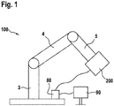
- a production facility 100 is shown in a simplified and schematic manner.
- the production facility 100 can be, for example, an industrial robot in a production hall, for example for an automobile body shop.
- the manufacturing device 100 has a support structure 3 arranged on a floor and two mutually connected and movable arms 4 and 5 arranged thereon. At the end of the arm 5, a punch riveting device 200 according to the invention is arranged in a preferred embodiment, which is only shown schematically here and is described in more detail below.
- a computing unit 80 is shown, which is, for example, a control unit of the punch riveting device 200.
- the computing unit 80 can also be provided as a control unit for the entire production facility, i.e. in addition to the punch riveting device, in particular also for controlling the movable arms.
- display means 90 for example a display, are provided on which, for example, current operating parameters of the punch riveting device can be displayed.
- the element 90 can also be a combined display / input means, for example a touch screen.
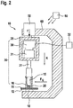
- FIG. 2 a punch riveting device 10, which is not according to the invention, is shown schematically, on which a problem is to be explained which is solved with the present invention.
- the punch riveting device 10 has a frame 60, which is preferably in the form of a C-frame or C-bracket, on which the individual components in a Self-piercing riveting devices are usually arranged in order to be able to assume the desired position relative to one another. Via the frame 60, the punch riveting device 10 can, for example, be attached to an arm as in FIG Figure 1 shown attached.
- the punch riveting device 10 has a punch (or a sonotrode) 15, for example with a round cross section.
- the punch 15 is surrounded radially by a (sleeve-shaped) hold-down device 16 and is arranged to be movable relative to it in the longitudinal direction.
- the hold-down device is preferably attached by means of a spring to a so-called zero amplitude passage of the stamp, ie a position of the stamp at which oscillation amplitudes are zero or at least as low as possible.
- the punch 15 is coupled to a drive 50 which is used to apply a force F in the joining direction R required to press a rivet 20 into the two components 11, 12.
- the drive 50 can for example be controlled by means of the computing unit 80.
- the force F can be specified via a setpoint value and recorded as an actual value.
- the hold-down device 16 is also set up to press against the surface of the component 11 facing the punch 15 with a hold-down force.
- a separate drive can be provided for this purpose, for example.
- the hold-down device can also (as shown here) be coupled to the drive of the punch or to the punch itself, for example by means of a spring.
- a counterholder in the form of a die 18 is arranged on the side of the two components 11, 12 opposite the punch 15 and the hold-down device 16.
- the punch 15 and the die 18, like the hold-down device 16, are arranged in the vertical direction and can be moved relative to one another, the die 18 itself generally not being movable.
- the hold-down 16 and the die 18 serve to clamp or compress the two components 11, 12 between the hold-down 16 and the die 18 during processing by the punch 15.
- the rivet 20 here by way of example a semi-hollow punch rivet, preferably consists of a material that is harder than the materials of the two components 11, 12, at least in the area of a rivet shaft.
- the flat upper side of the rivet facing away from the component 11 is arranged in operative connection with the punch 15, which rests flat against the upper side of the rivet 20.
- the stamp 15 is operatively connected to an (electro-mechanical) vibration converter 30, for example a piezo converter.
- the vibration converter 30 is in turn connected to an (electrical) vibration generator 32, for example an ultrasonic generator.
- an amplitude distance between maximum positive and negative amplitude of a vibration, especially measured at the interface between punch and rivet
- the vibration generator 32 is connected to the computing unit 80 (or can also be part of the computing unit) and can be controlled by it.
- the drive 50 can be, for example, a drive with a ball, roller, planetary thread or thread roller screw drive or the like, which is suitable for applying a force F for pressing the rivet 20 into the components 11, 12.
- a holding device 35 for example in the form of a frame or a rack, is attached to the drive 50.
- a vibration system 39 which in the present case comprises the vibration converter 30, a booster (amplitude amplifier) 31 and the stamp or the sonotrode 15 and the hold-down device 16, is arranged on the holding device 35.
- the high-frequency longitudinal vibration of the joining tool i.e. sonotrode 15, booster 31 and vibration converter 30, can cause the joining tool to wander sideways or to buckle or give way.
- Such lateral forces are in Figure 2 denoted by F Q as an example.
- F Q Such lateral forces
- Figure 2 the tilting of the joining tool or of the entire oscillating system 39 is also shown graphically.
- Such transverse forces are not known in previous, conventional punch riveting devices (without vibration or ultrasound support) in this order of magnitude, since the joining tool is not subjected to high-frequency longitudinal vibrations.
- Punch riveting devices according to the invention are shown schematically in various preferred embodiments.
- the basic components of these punch riveting devices correspond to the components of the punch riveting device 10 according to FIG Figure 2 and in this respect are also provided with the same reference symbols. In this respect, reference is also made to the description there. For the sake of clarity, however, some individual components are not shown.
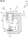
- a punch riveting device 200 according to the invention is shown schematically in a preferred embodiment.
- a drive and guide unit 70 is provided, which has the drive 50 and a guide device 75 as components.
- the guide device 75 here for example tubular with a round cross section, is arranged on the frame. It is conceivable that the guide device is formed integrally with the frame, but the guide device 75 can also be fastened to the frame in a suitable manner.
- the oscillating system 39 is arranged in a holder 35 which is comparable to that in FIG Figure 2 bracket shown can be.
- the oscillating system 39 is guided by means of the holder 35 in the guide device 75 and thus also in the drive and guide unit 70. This is done here by means of suitable bearings such as roller, ball or slide bearings.
- the drive 50 is arranged on the frame and has a lever 51 which, on the one hand, is rotatably attached to the guide device 75, for example by means of a suitable joint, and, on the other hand, is coupled to the holder 35 and thus to the oscillating system 39.
- the drive 50 is correspondingly attached to the lever 51.
- the drive 50 can otherwise, ie in particular with regard to its mode of operation, as in relation to FIG Figure 2 explained be trained.
- the oscillating system 39 can be guided and moved in a particularly stable manner in the joining direction R.
- any tilting or bending resulting from transverse forces can be avoided or at least reduced.
- the guide device 75 which can be designed to be particularly stable, as already explained in more detail at the beginning.
- the punch riveting device 200 is shown in a top view.
- the round cross section of the tubular guide device 75 with a central axis A can be seen here.
- the holder 35, which carries the oscillating system 39 also has a round cross section. Some or all of the parts of the oscillating system 39 can each have a round cross-section, preferably all with the same central axis A.
- bearings with bearing elements 76, for example balls, which are here distributed around the circumference, whereby a particularly uniform and thus stable guidance is achieved.
- the oscillating system can optionally also be guided without the holder 35 in the guide device 75 or the drive and guide unit 70, especially since a guide device with a round cross section is used here.
- a punch riveting device 300 according to the invention is shown schematically in a further preferred embodiment.
- the drive 50 is integrated into the guide device 75 as part of the drive and guide unit 70 and is designed in particular as a linear drive.
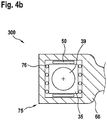
- Figure 4b which shows the punch riveting device 300 in a plan view
- the cross section of the tubular guide device 75 is rectangular.
- the bearings 76 are arranged here on two opposite sides, components of the drive or linear drive 50 are arranged on the other two sides. In this case, the uniform and stable guidance is achieved by the interaction of the bearings 76 with the drive 50 itself.
- the oscillating system generally has a round cross section
- the use of the holder 35 is expedient here.
- the holder 35 which can then have a rectangular cross section, enables the best possible guidance through the guide device 75 and thus the drive and guide unit 70.
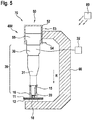
- a self-piercing riveting device 400 is shown schematically.
- the drive and guide unit 70 - in contrast to the punch riveting devices 200 and 300 - the drive and guide are structurally combined.
- the drive 50 itself, which is designed here as a hydraulic drive and is fastened or arranged on the frame 60, serves as a guide.
- the drive 50 has in particular a cylinder 52 with a piston 55 movably arranged therein.
- the drive 50 can be supplied with a suitable hydraulic fluid at the connections 53 and 54.
- the piston 55 here forms the component on which the oscillating system 39 is arranged centrally with respect to the joining direction R, i.e. the aforementioned first component, and the cylinder 52 forms the second component of the drive and guide unit 70, which is the first component or the piston 55 encloses in a section extending in the joining direction.
- the oscillating system 39 can be fastened to the piston 55 in a suitable manner. The use of a suitable holder is also conceivable here.
- a punch riveting device 500 not according to the invention is shown schematically.
- the punch riveting device 500 basically corresponds to the punch riveting device 400 according to FIG Figure 5
- a guide device 75 formed separately from the drive 50 is additionally provided, which can be arranged on the frame 60.
- the guide provided by the drive 50 itself and the guide by means of the guide device 75 are thus combined, so that an even more uniform and stable guide is made possible.
- the guide device 75 can be designed in a manner comparable to the guide device of the punch riveting device 200, but if necessary adapted in length in the joining direction R.
- a holder for the oscillating system 39 for guidance in the guide device 75 can also be provided here.
- the simultaneous use of such a holder for guidance in the guide device 75 and for attachment to the piston 55 is also conceivable.
Landscapes
- Engineering & Computer Science (AREA)
- Mechanical Engineering (AREA)
- Presses And Accessory Devices Thereof (AREA)
Claims (8)
- Dispositif de rivetage auto-perforant (200, 300, 400, 500) destiné à relier au moins deux composants (11, 12) au moyen d'un rivet (20), ledit dispositif comprenant
un poinçon (15) et un contre-support (18), entre lesquels les au moins deux composants (11, 12) et le rivet (20) peuvent être disposés,
un système vibrant (39) comportant le poinçon (15) et un convertisseur de vibrations (30) qui est couplé ou peut être couplé à un générateur de vibrations (32) de telle manière que le système vibrant (39) peut être excité de manière à vibrer, et un entraînement (50) au moyen duquel le système vibrant (39) et donc le poinçon (15) peuvent être soumis à une force (F) et peuvent être déplacés dans un sens d'assemblage (R) afin d'enfoncer un rivet (20), disposé entre le poinçon (15) et un composant (11), dirigé vers le poinçon, des au moins deux composants, au moyen du poinçon (15) dans les au moins deux composants (11, 12), caractérisé par
une unité combinée d'entraînement et de guidage (70) qui est destinée à guider le système vibrant (39) au moyen de paliers dans l'unité d'entraînement et de guidage (70) et dans le sens d'assemblage (R), qui comporte l'entraînement (50), qui est disposée sur un cadre (60) du dispositif de rivetage auto-perforant, et qui renferme le système vibrant (39) dans une portion qui s'étend dans le sens d'assemblage (R), l'unité d'entraînement et de guidage (70) comportant un moyen de guidage (75) qui est destiné à guider le système vibrant (39) au moyen de paliers dans l'unité de guidage (70), qui renferme, en tant que partie de l'unité d'entraînement et de guidage (70), le système vibrant (39) dans le sens d'assemblage, et qui est la partie de l'unité d'entraînement et de guidage (70) qui est disposée sur le cadre (60). - Dispositif de rivetage auto-perforant (200, 300, 500) selon la revendication 1, le moyen de guidage (75) étant un composant formé séparément de l'entraînement (50) .
- Dispositif de rivetage auto-perforant (200, 300) selon la revendication 2, le système vibrant (39) étant guidé directement ou au moyen d'un support (35) dans le dispositif de guidage (75).
- Dispositif de rivetage auto-perforant (200, 300) selon la revendication 2 ou 3, le dispositif de guidage (75) étant tubulaire avec une section transversale ronde ou rectangulaire.
- Dispositif de rivetage auto-perforant (200) selon l'une des revendications précédentes, l'entraînement (50) étant disposé sur le cadre (60) et étant accouplé au système vibrant (39) au moyen d'un levier (51).
- Dispositif de rivetage auto-perforant (300) selon l'une des revendications précédentes, l'entraînement (50) étant intégré dans le moyen de guidage (75) et étant conçu en particulier comme un entraînement linéaire.
- Dispositif de rivetage auto-perforant (200, 300, 400, 500) selon l'une des revendications précédentes, l'unité d'entraînement et de guidage (70) étant conçue de telle sorte qu'un point d'application de la force, produite par l'entraînement (50), sur le système vibrant étant situé dans un axe du système vibrant (39) qui s'étend dans le sens d'assemblage.
- Dispositif de rivetage auto-perforant (200, 300, 400, 500) selon l'une des revendications précédentes, le générateur de vibrations (32) étant conçu comme un générateur de sons, en particulier comme un générateur d'ultrasons.
Applications Claiming Priority (1)
| Application Number | Priority Date | Filing Date | Title |
|---|---|---|---|
| DE102018205531.9A DE102018205531A1 (de) | 2018-04-12 | 2018-04-12 | Stanznietvorrichtung |
Publications (2)
| Publication Number | Publication Date |
|---|---|
| EP3552730A1 EP3552730A1 (fr) | 2019-10-16 |
| EP3552730B1 true EP3552730B1 (fr) | 2021-01-27 |
Family
ID=65717746
Family Applications (1)
| Application Number | Title | Priority Date | Filing Date |
|---|---|---|---|
| EP19160713.4A Active EP3552730B1 (fr) | 2018-04-12 | 2019-03-05 | Dispositif rivet auto-poinçonneur |
Country Status (2)
| Country | Link |
|---|---|
| EP (1) | EP3552730B1 (fr) |
| DE (1) | DE102018205531A1 (fr) |
Families Citing this family (1)
| Publication number | Priority date | Publication date | Assignee | Title |
|---|---|---|---|---|
| DE102021126665A1 (de) | 2021-10-14 | 2023-04-20 | Herrmann Ultraschalltechnik Gmbh & Co. Kg | Ultraschallschwingsystem mit mechanischem Resonator |
Family Cites Families (7)
| Publication number | Priority date | Publication date | Assignee | Title |
|---|---|---|---|---|
| US3483611A (en) * | 1966-08-12 | 1969-12-16 | Cavitron Corp | Methods and apparatus for assembling parts together by ultrasonic energy |
| DE19905527B4 (de) * | 1999-02-10 | 2006-11-23 | Böllhoff GmbH | Vorrichtung zum Fügen von Werkstücken aus duktilem Material |
| GB0813883D0 (en) | 2008-07-30 | 2008-09-03 | Henrob Ltd | Joining apparatus and method |
| US10751789B2 (en) | 2014-01-16 | 2020-08-25 | Atlas Copco Ias Uk Limited | Linear actuator assembly |
| DE102014203357B4 (de) | 2014-02-25 | 2016-11-03 | Henkel Ag & Co. Kgaa | Darreichungseinheit für eine Masse |
| DE102014224596B4 (de) | 2014-12-02 | 2022-03-24 | Robert Bosch Gmbh | Stanznietzange mit Vibrationsunterstützung in X-Bauart |
| DE102016214534A1 (de) * | 2016-08-05 | 2018-02-08 | Robert Bosch Gmbh | Stanznietvorrichtung und Fertigungsvorrichtung |
-
2018
- 2018-04-12 DE DE102018205531.9A patent/DE102018205531A1/de not_active Withdrawn
-
2019
- 2019-03-05 EP EP19160713.4A patent/EP3552730B1/fr active Active
Non-Patent Citations (1)
| Title |
|---|
| None * |
Also Published As
| Publication number | Publication date |
|---|---|
| DE102018205531A1 (de) | 2019-10-17 |
| EP3552730A1 (fr) | 2019-10-16 |
Similar Documents
| Publication | Publication Date | Title |
|---|---|---|
| EP3505270B1 (fr) | Unité de frappe pour un dispositif de poinçonnage, dispositif de poinçonnage et procédé de fabrication d'un tel dispositif de poinçonnage | |
| EP3552729B1 (fr) | Dispositif d'installation de rivets auto-poinçonneurs | |
| EP3117924B1 (fr) | Procédé de liaison d'au moins deux composants au moyen d'un dispositif de rivetage et dispositif de fabrication | |
| DE102018220897A1 (de) | Setzeinheit für eine Stanznietvorrichtung, Stanznietvorrichtung und Verfahren zum Verbinden von Bauteilen | |
| EP3120951B1 (fr) | Dispositif de rivetage et dispositif de fabrication | |
| EP3117923B1 (fr) | Procédé de liaison d'au moins deux composants au moyen d'un dispositif de rivetage et dispositif de fabrication | |
| WO2000018528A1 (fr) | Procede et dispositif pour assembler des elements sous forme de plaques qui se chevauchent | |
| EP3120950B1 (fr) | Élément de transmission pour un dispositif de rivetage, dispositif de rivetage, dispositif de fabrication et procé de détermination d'un comportement aux vibrations | |
| DE102019107539A1 (de) | Gestell für eine Bearbeitungsmaschine und Verfahren zum Bearbeiten eines Werkstücks mit derselben | |
| EP3281721B1 (fr) | Procédé de fixation d'au moins deux composants au moyen d'un dispositif de rivetage auto-poinconnant et dispositif de fabrication | |
| EP3552730A1 (fr) | Dispositif rivet auto-poinçonneur | |
| EP3117925B1 (fr) | Dispositif de rivetage et dispositif de fabrication | |
| EP3552731B1 (fr) | Unité de pose pour un dispositif rivet auto-poinçonneur et dispositif rivet auto-poinçonneur | |
| EP3381581B1 (fr) | Dispositif de poinçonnage et procédé de fonctionnement d'un dispositif de poinçonnage | |
| DE19945743A1 (de) | Verfahren und Vorrichtung zum Verbinden von sich überlappenden plattenförmigen Bauteilen | |
| DE102018205621A1 (de) | Stanznietvorrichtung mit Zuführeinheit für Niete | |
| EP3546084B1 (fr) | Procédé de liaison d'au moins deux composants au moyen d'un dispositif de rivetage et dispositif de rivetage | |
| DE102018222841A1 (de) | Setzeinheit für eine Stanznietvorrichtung, Stanznietvorrichtung und Verfahren zum Verbinden von Bauteilen | |
| DE102017213233A1 (de) | Stanznietvorrichtung und Verfahren zum Verbinden von Bauteilen | |
| EP1762315B1 (fr) | Dispositif de connection par déformation plastique | |
| DE102017209264A1 (de) | Stanznietvorrichtung mit Schwingungserzeuger und Beschleunigungssensor | |
| DE102006053223B3 (de) | Loch- und Durchzugsstempel | |
| DE102016214534A1 (de) | Stanznietvorrichtung und Fertigungsvorrichtung | |
| DE102017209020A1 (de) | Fügevorrichtung und Verfahren zum Betreiben einer Fügevorrichtung | |
| DE102017205659A1 (de) | Stanznietvorrichtung zum setzen eines stanzniets mit einer eine stempelkraft unterstützenden schwingung und verfahren zum stanznieten mit einer solchen stanznietvorrichtung |
Legal Events
| Date | Code | Title | Description |
|---|---|---|---|
| PUAI | Public reference made under article 153(3) epc to a published international application that has entered the european phase |
Free format text: ORIGINAL CODE: 0009012 |
|
| STAA | Information on the status of an ep patent application or granted ep patent |
Free format text: STATUS: THE APPLICATION HAS BEEN PUBLISHED |
|
| AK | Designated contracting states |
Kind code of ref document: A1 Designated state(s): AL AT BE BG CH CY CZ DE DK EE ES FI FR GB GR HR HU IE IS IT LI LT LU LV MC MK MT NL NO PL PT RO RS SE SI SK SM TR |
|
| AX | Request for extension of the european patent |
Extension state: BA ME |
|
| STAA | Information on the status of an ep patent application or granted ep patent |
Free format text: STATUS: REQUEST FOR EXAMINATION WAS MADE |
|
| RAP1 | Party data changed (applicant data changed or rights of an application transferred) |
Owner name: ROBERT BOSCH GMBH |
|
| 17P | Request for examination filed |
Effective date: 20200416 |
|
| RBV | Designated contracting states (corrected) |
Designated state(s): AL AT BE BG CH CY CZ DE DK EE ES FI FR GB GR HR HU IE IS IT LI LT LU LV MC MK MT NL NO PL PT RO RS SE SI SK SM TR |
|
| GRAP | Despatch of communication of intention to grant a patent |
Free format text: ORIGINAL CODE: EPIDOSNIGR1 |
|
| STAA | Information on the status of an ep patent application or granted ep patent |
Free format text: STATUS: GRANT OF PATENT IS INTENDED |
|
| RIC1 | Information provided on ipc code assigned before grant |
Ipc: B21J 15/02 20060101AFI20200915BHEP Ipc: B21J 15/16 20060101ALI20200915BHEP Ipc: B21J 15/12 20060101ALI20200915BHEP Ipc: B21J 15/24 20060101ALI20200915BHEP |
|
| INTG | Intention to grant announced |
Effective date: 20201016 |
|
| GRAS | Grant fee paid |
Free format text: ORIGINAL CODE: EPIDOSNIGR3 |
|
| GRAA | (expected) grant |
Free format text: ORIGINAL CODE: 0009210 |
|
| STAA | Information on the status of an ep patent application or granted ep patent |
Free format text: STATUS: THE PATENT HAS BEEN GRANTED |
|
| AK | Designated contracting states |
Kind code of ref document: B1 Designated state(s): AL AT BE BG CH CY CZ DE DK EE ES FI FR GB GR HR HU IE IS IT LI LT LU LV MC MK MT NL NO PL PT RO RS SE SI SK SM TR |
|
| REG | Reference to a national code |
Ref country code: GB Ref legal event code: FG4D Free format text: NOT ENGLISH |
|
| REG | Reference to a national code |
Ref country code: CH Ref legal event code: EP |
|
| REG | Reference to a national code |
Ref country code: AT Ref legal event code: REF Ref document number: 1357878 Country of ref document: AT Kind code of ref document: T Effective date: 20210215 |
|
| REG | Reference to a national code |
Ref country code: IE Ref legal event code: FG4D Free format text: LANGUAGE OF EP DOCUMENT: GERMAN |
|
| REG | Reference to a national code |
Ref country code: DE Ref legal event code: R096 Ref document number: 502019000751 Country of ref document: DE |
|
| REG | Reference to a national code |
Ref country code: NL Ref legal event code: MP Effective date: 20210127 |
|
| REG | Reference to a national code |
Ref country code: LT Ref legal event code: MG9D |
|
| PG25 | Lapsed in a contracting state [announced via postgrant information from national office to epo] |
Ref country code: LT Free format text: LAPSE BECAUSE OF FAILURE TO SUBMIT A TRANSLATION OF THE DESCRIPTION OR TO PAY THE FEE WITHIN THE PRESCRIBED TIME-LIMIT Effective date: 20210127 Ref country code: PT Free format text: LAPSE BECAUSE OF FAILURE TO SUBMIT A TRANSLATION OF THE DESCRIPTION OR TO PAY THE FEE WITHIN THE PRESCRIBED TIME-LIMIT Effective date: 20210527 Ref country code: NO Free format text: LAPSE BECAUSE OF FAILURE TO SUBMIT A TRANSLATION OF THE DESCRIPTION OR TO PAY THE FEE WITHIN THE PRESCRIBED TIME-LIMIT Effective date: 20210427 Ref country code: BG Free format text: LAPSE BECAUSE OF FAILURE TO SUBMIT A TRANSLATION OF THE DESCRIPTION OR TO PAY THE FEE WITHIN THE PRESCRIBED TIME-LIMIT Effective date: 20210427 Ref country code: GR Free format text: LAPSE BECAUSE OF FAILURE TO SUBMIT A TRANSLATION OF THE DESCRIPTION OR TO PAY THE FEE WITHIN THE PRESCRIBED TIME-LIMIT Effective date: 20210428 Ref country code: FI Free format text: LAPSE BECAUSE OF FAILURE TO SUBMIT A TRANSLATION OF THE DESCRIPTION OR TO PAY THE FEE WITHIN THE PRESCRIBED TIME-LIMIT Effective date: 20210127 Ref country code: HR Free format text: LAPSE BECAUSE OF FAILURE TO SUBMIT A TRANSLATION OF THE DESCRIPTION OR TO PAY THE FEE WITHIN THE PRESCRIBED TIME-LIMIT Effective date: 20210127 |
|
| PG25 | Lapsed in a contracting state [announced via postgrant information from national office to epo] |
Ref country code: SE Free format text: LAPSE BECAUSE OF FAILURE TO SUBMIT A TRANSLATION OF THE DESCRIPTION OR TO PAY THE FEE WITHIN THE PRESCRIBED TIME-LIMIT Effective date: 20210127 Ref country code: LV Free format text: LAPSE BECAUSE OF FAILURE TO SUBMIT A TRANSLATION OF THE DESCRIPTION OR TO PAY THE FEE WITHIN THE PRESCRIBED TIME-LIMIT Effective date: 20210127 Ref country code: PL Free format text: LAPSE BECAUSE OF FAILURE TO SUBMIT A TRANSLATION OF THE DESCRIPTION OR TO PAY THE FEE WITHIN THE PRESCRIBED TIME-LIMIT Effective date: 20210127 Ref country code: RS Free format text: LAPSE BECAUSE OF FAILURE TO SUBMIT A TRANSLATION OF THE DESCRIPTION OR TO PAY THE FEE WITHIN THE PRESCRIBED TIME-LIMIT Effective date: 20210127 |
|
| PG25 | Lapsed in a contracting state [announced via postgrant information from national office to epo] |
Ref country code: IS Free format text: LAPSE BECAUSE OF FAILURE TO SUBMIT A TRANSLATION OF THE DESCRIPTION OR TO PAY THE FEE WITHIN THE PRESCRIBED TIME-LIMIT Effective date: 20210527 |
|
| REG | Reference to a national code |
Ref country code: DE Ref legal event code: R097 Ref document number: 502019000751 Country of ref document: DE |
|
| PG25 | Lapsed in a contracting state [announced via postgrant information from national office to epo] |
Ref country code: MC Free format text: LAPSE BECAUSE OF FAILURE TO SUBMIT A TRANSLATION OF THE DESCRIPTION OR TO PAY THE FEE WITHIN THE PRESCRIBED TIME-LIMIT Effective date: 20210127 Ref country code: EE Free format text: LAPSE BECAUSE OF FAILURE TO SUBMIT A TRANSLATION OF THE DESCRIPTION OR TO PAY THE FEE WITHIN THE PRESCRIBED TIME-LIMIT Effective date: 20210127 Ref country code: CZ Free format text: LAPSE BECAUSE OF FAILURE TO SUBMIT A TRANSLATION OF THE DESCRIPTION OR TO PAY THE FEE WITHIN THE PRESCRIBED TIME-LIMIT Effective date: 20210127 Ref country code: SM Free format text: LAPSE BECAUSE OF FAILURE TO SUBMIT A TRANSLATION OF THE DESCRIPTION OR TO PAY THE FEE WITHIN THE PRESCRIBED TIME-LIMIT Effective date: 20210127 |
|
| PG25 | Lapsed in a contracting state [announced via postgrant information from national office to epo] |
Ref country code: DK Free format text: LAPSE BECAUSE OF FAILURE TO SUBMIT A TRANSLATION OF THE DESCRIPTION OR TO PAY THE FEE WITHIN THE PRESCRIBED TIME-LIMIT Effective date: 20210127 Ref country code: RO Free format text: LAPSE BECAUSE OF FAILURE TO SUBMIT A TRANSLATION OF THE DESCRIPTION OR TO PAY THE FEE WITHIN THE PRESCRIBED TIME-LIMIT Effective date: 20210127 Ref country code: SK Free format text: LAPSE BECAUSE OF FAILURE TO SUBMIT A TRANSLATION OF THE DESCRIPTION OR TO PAY THE FEE WITHIN THE PRESCRIBED TIME-LIMIT Effective date: 20210127 |
|
| PLBE | No opposition filed within time limit |
Free format text: ORIGINAL CODE: 0009261 |
|
| STAA | Information on the status of an ep patent application or granted ep patent |
Free format text: STATUS: NO OPPOSITION FILED WITHIN TIME LIMIT |
|
| REG | Reference to a national code |
Ref country code: BE Ref legal event code: MM Effective date: 20210331 |
|
| 26N | No opposition filed |
Effective date: 20211028 |
|
| PG25 | Lapsed in a contracting state [announced via postgrant information from national office to epo] |
Ref country code: ES Free format text: LAPSE BECAUSE OF FAILURE TO SUBMIT A TRANSLATION OF THE DESCRIPTION OR TO PAY THE FEE WITHIN THE PRESCRIBED TIME-LIMIT Effective date: 20210127 Ref country code: FR Free format text: LAPSE BECAUSE OF NON-PAYMENT OF DUE FEES Effective date: 20210327 Ref country code: AL Free format text: LAPSE BECAUSE OF FAILURE TO SUBMIT A TRANSLATION OF THE DESCRIPTION OR TO PAY THE FEE WITHIN THE PRESCRIBED TIME-LIMIT Effective date: 20210127 Ref country code: LU Free format text: LAPSE BECAUSE OF NON-PAYMENT OF DUE FEES Effective date: 20210305 Ref country code: IE Free format text: LAPSE BECAUSE OF NON-PAYMENT OF DUE FEES Effective date: 20210305 |
|
| PG25 | Lapsed in a contracting state [announced via postgrant information from national office to epo] |
Ref country code: SI Free format text: LAPSE BECAUSE OF FAILURE TO SUBMIT A TRANSLATION OF THE DESCRIPTION OR TO PAY THE FEE WITHIN THE PRESCRIBED TIME-LIMIT Effective date: 20210127 |
|
| PG25 | Lapsed in a contracting state [announced via postgrant information from national office to epo] |
Ref country code: IT Free format text: LAPSE BECAUSE OF FAILURE TO SUBMIT A TRANSLATION OF THE DESCRIPTION OR TO PAY THE FEE WITHIN THE PRESCRIBED TIME-LIMIT Effective date: 20210127 |
|
| PG25 | Lapsed in a contracting state [announced via postgrant information from national office to epo] |
Ref country code: IS Free format text: LAPSE BECAUSE OF FAILURE TO SUBMIT A TRANSLATION OF THE DESCRIPTION OR TO PAY THE FEE WITHIN THE PRESCRIBED TIME-LIMIT Effective date: 20210527 |
|
| PG25 | Lapsed in a contracting state [announced via postgrant information from national office to epo] |
Ref country code: BE Free format text: LAPSE BECAUSE OF NON-PAYMENT OF DUE FEES Effective date: 20210331 |
|
| REG | Reference to a national code |
Ref country code: CH Ref legal event code: PL |
|
| PG25 | Lapsed in a contracting state [announced via postgrant information from national office to epo] |
Ref country code: LI Free format text: LAPSE BECAUSE OF NON-PAYMENT OF DUE FEES Effective date: 20220331 Ref country code: CH Free format text: LAPSE BECAUSE OF NON-PAYMENT OF DUE FEES Effective date: 20220331 |
|
| PG25 | Lapsed in a contracting state [announced via postgrant information from national office to epo] |
Ref country code: NL Free format text: LAPSE BECAUSE OF NON-PAYMENT OF DUE FEES Effective date: 20210127 Ref country code: CY Free format text: LAPSE BECAUSE OF FAILURE TO SUBMIT A TRANSLATION OF THE DESCRIPTION OR TO PAY THE FEE WITHIN THE PRESCRIBED TIME-LIMIT Effective date: 20210127 |
|
| PG25 | Lapsed in a contracting state [announced via postgrant information from national office to epo] |
Ref country code: HU Free format text: LAPSE BECAUSE OF FAILURE TO SUBMIT A TRANSLATION OF THE DESCRIPTION OR TO PAY THE FEE WITHIN THE PRESCRIBED TIME-LIMIT; INVALID AB INITIO Effective date: 20190305 |
|
| GBPC | Gb: european patent ceased through non-payment of renewal fee |
Effective date: 20230305 |
|
| PG25 | Lapsed in a contracting state [announced via postgrant information from national office to epo] |
Ref country code: GB Free format text: LAPSE BECAUSE OF NON-PAYMENT OF DUE FEES Effective date: 20230305 |
|
| PG25 | Lapsed in a contracting state [announced via postgrant information from national office to epo] |
Ref country code: GB Free format text: LAPSE BECAUSE OF NON-PAYMENT OF DUE FEES Effective date: 20230305 |
|
| PG25 | Lapsed in a contracting state [announced via postgrant information from national office to epo] |
Ref country code: MK Free format text: LAPSE BECAUSE OF FAILURE TO SUBMIT A TRANSLATION OF THE DESCRIPTION OR TO PAY THE FEE WITHIN THE PRESCRIBED TIME-LIMIT Effective date: 20210127 |
|
| PG25 | Lapsed in a contracting state [announced via postgrant information from national office to epo] |
Ref country code: TR Free format text: LAPSE BECAUSE OF FAILURE TO SUBMIT A TRANSLATION OF THE DESCRIPTION OR TO PAY THE FEE WITHIN THE PRESCRIBED TIME-LIMIT Effective date: 20210127 |
|
| PG25 | Lapsed in a contracting state [announced via postgrant information from national office to epo] |
Ref country code: MT Free format text: LAPSE BECAUSE OF FAILURE TO SUBMIT A TRANSLATION OF THE DESCRIPTION OR TO PAY THE FEE WITHIN THE PRESCRIBED TIME-LIMIT Effective date: 20210127 |
|
| REG | Reference to a national code |
Ref country code: AT Ref legal event code: MM01 Ref document number: 1357878 Country of ref document: AT Kind code of ref document: T Effective date: 20240305 |
|
| PG25 | Lapsed in a contracting state [announced via postgrant information from national office to epo] |
Ref country code: AT Free format text: LAPSE BECAUSE OF NON-PAYMENT OF DUE FEES Effective date: 20240305 |
|
| PGFP | Annual fee paid to national office [announced via postgrant information from national office to epo] |
Ref country code: AT Payment date: 20260410 Year of fee payment: 5 |
|
| PGFP | Annual fee paid to national office [announced via postgrant information from national office to epo] |
Ref country code: DE Payment date: 20260526 Year of fee payment: 8 |