EP3552862A1 - Ladestecker zur versorgung eines elektrofahrzeugs mit elektrischer energie, ladestation mit dem ladestecker, ladeempfänger für ein elektrofahrzeug und verfahren zum verbinden des ladeempfängers und des ladesteckers - Google Patents
Ladestecker zur versorgung eines elektrofahrzeugs mit elektrischer energie, ladestation mit dem ladestecker, ladeempfänger für ein elektrofahrzeug und verfahren zum verbinden des ladeempfängers und des ladesteckers Download PDFInfo
- Publication number
- EP3552862A1 EP3552862A1 EP18305428.7A EP18305428A EP3552862A1 EP 3552862 A1 EP3552862 A1 EP 3552862A1 EP 18305428 A EP18305428 A EP 18305428A EP 3552862 A1 EP3552862 A1 EP 3552862A1
- Authority
- EP
- European Patent Office
- Prior art keywords
- charger plug
- electric
- electric connector
- charging receiver
- protection lid
- Prior art date
- Legal status (The legal status is an assumption and is not a legal conclusion. Google has not performed a legal analysis and makes no representation as to the accuracy of the status listed.)
- Granted
Links
Images


Classifications
-
- B—PERFORMING OPERATIONS; TRANSPORTING
- B60—VEHICLES IN GENERAL
- B60L—PROPULSION OF ELECTRICALLY-PROPELLED VEHICLES; SUPPLYING ELECTRIC POWER FOR AUXILIARY EQUIPMENT OF ELECTRICALLY-PROPELLED VEHICLES; ELECTRODYNAMIC BRAKE SYSTEMS FOR VEHICLES IN GENERAL; MAGNETIC SUSPENSION OR LEVITATION FOR VEHICLES; MONITORING OPERATING VARIABLES OF ELECTRICALLY-PROPELLED VEHICLES; ELECTRIC SAFETY DEVICES FOR ELECTRICALLY-PROPELLED VEHICLES
- B60L53/00—Methods of charging batteries, specially adapted for electric vehicles; Charging stations or on-board charging equipment therefor; Exchange of energy storage elements in electric vehicles
- B60L53/30—Constructional details of charging stations
- B60L53/35—Means for automatic or assisted adjustment of the relative position of charging devices and vehicles
- B60L53/36—Means for automatic or assisted adjustment of the relative position of charging devices and vehicles by positioning the vehicle
-
- B—PERFORMING OPERATIONS; TRANSPORTING
- B60—VEHICLES IN GENERAL
- B60L—PROPULSION OF ELECTRICALLY-PROPELLED VEHICLES; SUPPLYING ELECTRIC POWER FOR AUXILIARY EQUIPMENT OF ELECTRICALLY-PROPELLED VEHICLES; ELECTRODYNAMIC BRAKE SYSTEMS FOR VEHICLES IN GENERAL; MAGNETIC SUSPENSION OR LEVITATION FOR VEHICLES; MONITORING OPERATING VARIABLES OF ELECTRICALLY-PROPELLED VEHICLES; ELECTRIC SAFETY DEVICES FOR ELECTRICALLY-PROPELLED VEHICLES
- B60L53/00—Methods of charging batteries, specially adapted for electric vehicles; Charging stations or on-board charging equipment therefor; Exchange of energy storage elements in electric vehicles
- B60L53/10—Methods of charging batteries, specially adapted for electric vehicles; Charging stations or on-board charging equipment therefor; Exchange of energy storage elements in electric vehicles characterised by the energy transfer between the charging station and the vehicle
- B60L53/14—Conductive energy transfer
-
- B—PERFORMING OPERATIONS; TRANSPORTING
- B60—VEHICLES IN GENERAL
- B60L—PROPULSION OF ELECTRICALLY-PROPELLED VEHICLES; SUPPLYING ELECTRIC POWER FOR AUXILIARY EQUIPMENT OF ELECTRICALLY-PROPELLED VEHICLES; ELECTRODYNAMIC BRAKE SYSTEMS FOR VEHICLES IN GENERAL; MAGNETIC SUSPENSION OR LEVITATION FOR VEHICLES; MONITORING OPERATING VARIABLES OF ELECTRICALLY-PROPELLED VEHICLES; ELECTRIC SAFETY DEVICES FOR ELECTRICALLY-PROPELLED VEHICLES
- B60L53/00—Methods of charging batteries, specially adapted for electric vehicles; Charging stations or on-board charging equipment therefor; Exchange of energy storage elements in electric vehicles
- B60L53/30—Constructional details of charging stations
- B60L53/35—Means for automatic or assisted adjustment of the relative position of charging devices and vehicles
-
- Y—GENERAL TAGGING OF NEW TECHNOLOGICAL DEVELOPMENTS; GENERAL TAGGING OF CROSS-SECTIONAL TECHNOLOGIES SPANNING OVER SEVERAL SECTIONS OF THE IPC; TECHNICAL SUBJECTS COVERED BY FORMER USPC CROSS-REFERENCE ART COLLECTIONS [XRACs] AND DIGESTS
- Y02—TECHNOLOGIES OR APPLICATIONS FOR MITIGATION OR ADAPTATION AGAINST CLIMATE CHANGE
- Y02T—CLIMATE CHANGE MITIGATION TECHNOLOGIES RELATED TO TRANSPORTATION
- Y02T10/00—Road transport of goods or passengers
- Y02T10/60—Other road transportation technologies with climate change mitigation effect
- Y02T10/70—Energy storage systems for electromobility, e.g. batteries
-
- Y—GENERAL TAGGING OF NEW TECHNOLOGICAL DEVELOPMENTS; GENERAL TAGGING OF CROSS-SECTIONAL TECHNOLOGIES SPANNING OVER SEVERAL SECTIONS OF THE IPC; TECHNICAL SUBJECTS COVERED BY FORMER USPC CROSS-REFERENCE ART COLLECTIONS [XRACs] AND DIGESTS
- Y02—TECHNOLOGIES OR APPLICATIONS FOR MITIGATION OR ADAPTATION AGAINST CLIMATE CHANGE
- Y02T—CLIMATE CHANGE MITIGATION TECHNOLOGIES RELATED TO TRANSPORTATION
- Y02T10/00—Road transport of goods or passengers
- Y02T10/60—Other road transportation technologies with climate change mitigation effect
- Y02T10/7072—Electromobility specific charging systems or methods for batteries, ultracapacitors, supercapacitors or double-layer capacitors
-
- Y—GENERAL TAGGING OF NEW TECHNOLOGICAL DEVELOPMENTS; GENERAL TAGGING OF CROSS-SECTIONAL TECHNOLOGIES SPANNING OVER SEVERAL SECTIONS OF THE IPC; TECHNICAL SUBJECTS COVERED BY FORMER USPC CROSS-REFERENCE ART COLLECTIONS [XRACs] AND DIGESTS
- Y02—TECHNOLOGIES OR APPLICATIONS FOR MITIGATION OR ADAPTATION AGAINST CLIMATE CHANGE
- Y02T—CLIMATE CHANGE MITIGATION TECHNOLOGIES RELATED TO TRANSPORTATION
- Y02T90/00—Enabling technologies or technologies with a potential or indirect contribution to GHG emissions mitigation
- Y02T90/10—Technologies relating to charging of electric vehicles
- Y02T90/12—Electric charging stations
-
- Y—GENERAL TAGGING OF NEW TECHNOLOGICAL DEVELOPMENTS; GENERAL TAGGING OF CROSS-SECTIONAL TECHNOLOGIES SPANNING OVER SEVERAL SECTIONS OF THE IPC; TECHNICAL SUBJECTS COVERED BY FORMER USPC CROSS-REFERENCE ART COLLECTIONS [XRACs] AND DIGESTS
- Y02—TECHNOLOGIES OR APPLICATIONS FOR MITIGATION OR ADAPTATION AGAINST CLIMATE CHANGE
- Y02T—CLIMATE CHANGE MITIGATION TECHNOLOGIES RELATED TO TRANSPORTATION
- Y02T90/00—Enabling technologies or technologies with a potential or indirect contribution to GHG emissions mitigation
- Y02T90/10—Technologies relating to charging of electric vehicles
- Y02T90/14—Plug-in electric vehicles
Definitions
- the invention relates to the field of electric vehicles.
- the invention relates to a charger plug for supplying electric energy to an electric vehicle, a charging station comprising said charger plug, a charging receiver for an electric vehicle suitable for being mounted on the bottom of the electric vehicle and arranged to be coupled with the charger plug and a method for connecting said charging receiver and said charger plug.
- This invention has as its object to remedy to these drawbacks by proposing a charger plug and a charging receiver configured to be easily connected and protected from the outdoor conditions and by proposing a method for connecting said charging receiver and said charger plug, which is easy to implement while protecting said charging receiver and said charger plug from the outdoor conditions.
- the present invention relates to a charger plug for supplying electric energy to an electric vehicle, the charger plug comprising at least a first electric connector comprising at least one first electric contact, a support comprising a bottom face on which the first electric connector is mounted and an upper face arranged to slide on the bottom of the electric vehicle, the first electric connector being arranged to be coupled with a corresponding second electric connector of a charging receiver located on the bottom of the electric vehicle so that the at least one first electric contact being electrically connected with at least one second electric contact of the second electric connector, charger plug characterized in that the support comprises guiding means comprising a reception area arranged to surround at least partially the charging receiver and arranged to align the first electric connector and the second electric connector, when moving the charger plug in the direction of the charging receiver or conversely.
- the present invention also relates to a charging station comprising at least one arm connected to charger plug by connection means, and comprising at least one actuator to move the at least one arm characterized in that the charging station comprises a charger plug according to the invention.
- the present invention also relates to a charging receiver for an electric vehicle suitable for being mounted on the bottom of the electric vehicle and arranged to be coupled with the charger plug according to the invention, the charging receiver comprising at least one second electric connector arranged to be coupled with the first electric connector of the charger plug, the second electric connector comprising at least one second electric contact arranged to be electrically coupled with at least one first electric contact of the first electric connector of the charger plug, the charging receiver comprising a rotatable protection lid movable in rotation from a first position where the protection lid covers the second electric connector to protect the second electric contact and a second position where the protection lid uncovers the second electric connector to enable the electric connection between the second electric contact and the first electric contact, charging receiver characterized in that the protection lid comprises means for opening the protection lid arranged so that the protection lid tilts from the first position to the second position when it cooperates with corresponding means for opening the protection lid of the charger plug.
- the present invention also relates to a method for connecting a charging receiver of an electric vehicle and a charger plug of a charging station, the charging station being located on the ground and being suitable to be located underneath the bottom of the electric vehicle, the charging station comprising the charger plug which comprises a first electric connector, at least one arm connected to the charger plug by connection means and at least an actuator to move the at least one arm, the charging receiver being mounted on the bottom of the electric vehicle and comprising a second electric connector, the charger plug comprising guiding means comprising a reception area arranged to surround at least partially the charging receiver and arranged to align the first electric connector and the second electric connector, when moving the charger plug in the direction of the charging receiver or conversely, method comprising the steps of:
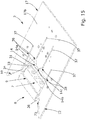
- the figures 1A , 1B , 2 , 3A , 3B , 4A , 4B , 4C , 5A , 5B , 6A , 6B , 6C , 7A , 7B , 8 , 9A , 9B , 10 , 11 , 13 , 15 , 16 and 18 show a charger plug 2 for supplying electric energy to an electric vehicle 3, the charger plug 2 comprising at least a first electric connector 4 comprising at least one first electric contact 5, a support 17 comprising a bottom face 17a on which the first electric connector 4 is mounted and an upper face 17b arranged to slide on the bottom 3' of the electric vehicle 3, the first electric connector 4 being arranged to be coupled with a corresponding second electric connector 7 of a charging receiver 8 located on the bottom 3' of the electric vehicle 3 so that the at least one first electric contact 5 being electrically connected with at least one second electric contact 6 of the second electric connector 7.
- the charger plug 2 is characterized in that the support 17 comprises guiding means 10, 12 comprising a reception area 14 arranged to surround at least partially the charging receiver 8 and arranged to align the first electric connector 4 and the second electric connector 7, when moving the charger plug 2 in the direction of the charging receiver 8 or conversely.
- the guiding means 10, 12 are provided to mechanically align the first electric connector 4 with the second electric connector 7 of the charging receiver 8, so that they can connect properly to charge the battery of the electric vehicle 3 with electric energy. This auto-alignment between the charger plug 2 and the charging receiver 8 is shown in figure 4B .
- These mechanical guiding means 10, 12 advantageously are not likely to be damaged because of extreme temperatures, rain, snow, ice, external corrosion and/or dust.
- the upper face 17b can slide on the bottom 3' of the electric vehicle 3 in the direction of the charging receiver 8 ( figures 4A , 4B , 4C , 5A , 5B ), until the guiding means 10, 12 lean against the charging receiver 8 and that the reception area 14 and a portion of complementary shape of the charging receiver 8 connect together ( figures 6A , 6B , 6C , 10 , 11 , 15 , 16 ).
- the bottom 3' of the electric vehicle 3 can slide on the upper face 17b ( figures 4A , 4B , 4C , 5A , 5B ), until the guiding means 10, 12 lean against the charging receiver 8 and that the reception area 14 and a portion of complementary shape of the charging receiver 8 connect together ( figures 7A , 7B , 9A , 9B , 10 , 11 , 15 , 16 ).
- the portion of complementary shape of the charging receiver 8 is located on the side of a second contact wall 9 of the charging receiver 8 comprising the second electric connector 7 ( figures 10 , 15 and 17 ).
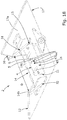
- the reception area 14 is located on the side of a first contact wall 16 comprising the first electric connector 4 ( figures 10 , 13 and 18 ). Then, when the portion of complementary shape of the charging receiver 8 and the reception area 14 connect, the first electric connector 4 is in front of the second electric connector 7.
- the charging receiver 8 comprises a protection lid 25, the portion of complementary shape consists of a portion of this protection lid 25.
- the first electric connector 4 is in front of the protection lid 25 behind which the second electric connector 7 is located as long as the protection lid 25 covers the second electric connector 7.
- the protection lid 25 uncovers the second electric connector 7, then the first electric connector 4 is in front of the second electric connector 7 ( figures 10 and 16 ).
- the guiding means comprises a first member 10 projecting from the support 17 on a first lateral side 11 of the first electric connector 4 and a second member 12 projecting from the support 17 on a second lateral side 13 of the first electric connector 4 respectively delimiting a first portion 14a and a second portion 14b of the reception area 14, the first member 10 and the second member 12 being positioned at a predetermined distance D from one to another and being separated from one to another by a base portion 14c of the reception area 14.
- the reception area 14 has a U-shaped delimited by the first portion 14a, the second portion 14b and the base portion 14c ( figures 10 , 11 , 13 , 15 and 18 ).
- the charger plug 2 comprises means 15; 31, 32 for opening a protection lid 25 of the charging receiver 8 arranged to cooperate with corresponding means 26; 33, 35 for opening the protection lid 25 of the charging receiver 8.
- the protection lid 25 of the charging receiver 8 are provided to automatically open the protection lid 25, after the connection between the portion of the protection lid 25 and the reception area 14, so that the protection lid 25 uncovers the second electric connector 7 to enable the electric connection between the second electric contact 6 and the first electric contact 5.
- the protection lid 25 enables protecting the second electric connector 7 from the outdoor conditions as long as it is not connected to first electric connector 4, without disturbing a subsequent connection with the first electric connector 4, thanks to the means for opening 26, 33, 35 the protection lid 25.
- the means for opening the protection lid 25 consist of a protrusion 15 projecting from the reception area 14 of the support 17, the protrusion 15 being arranged to cooperate with the corresponding means for opening the protection lid 25 of the charging receiver 8 consisting of a guiding slot 26 of the protection lid 25 comprising an inclined wall 27.
- This protrusion 15 is provided to lean against the inclined wall 27, when the charger plug 2 and the charging receiver 8 are moved relative to each other, in order to rotate the protection lid 25 from a first position PI to a second position P2, in the clockwise direction and then uncover the second electric connector 7.
- the protrusion consists of a wheel 15 ( figures 10 , 11 and 13 ).
- the means for opening the protection lid 25 comprise a first inclined guide rail 31 projecting from the bottom face 17a of the support 17 and surrounding the first lateral side 11 of the first electric connector 4, and a second inclined guide rail 32 projecting from the bottom face 17a of the support 17 and surrounding the second lateral side 13 of the first electric connector 4, the first inclined guide rail 31 and the second inclined guide rail 32 being arranged to cooperate respectively with the corresponding means for opening the protection lid 25 of the charging receiver 8 consisting of a first protrusion 33 projecting from a first lateral wall 34 of the protection lid 25 of the charging receiver 8 and a second protrusion 35 projecting from a second lateral wall 36 of the protection lid 25.
- first inclined guide rail 31 and second inclined guide rail 32 respectively are provided to lean against the first protrusion 33 and second protrusion 35, when the charger plug 2 and the charging receiver 8 are moved relative to each other, in order to rotate the protection lid 25 from a first position PI to a second position P2, in the clockwise direction and then uncover the second electric connector 7.
- the first inclined guide rail 31 protrudes perpendicularly to the bottom face 17a along the first portion 14a of the reception area 14 and the second inclined guide rail 32 protrudes perpendicularly to the bottom face 17a along the second portion 14b of the reception area 14.
- the support 17 has a planar shape comprising the bottom face 17a on which the first electric connector 4 is mounted and the upper face 17b arranged to slide on the bottom 3' of the electric vehicle 3.
- This planar shape is provided to ease the sliding of the support 17 with respect to the bottom 3' of the electric vehicle 3.
- the support 17 comprises at least a guiding wheel 18, 19, as shown in figures 3B , 4B , 4C , 5B , 6B , 6C , 7B , 9B , 10 , 11 and 13 .
- This guiding wheel 18, 19 is provided to improve the sliding of the charger plug 2 on the bottom 3' of the electric vehicle 3.
- a first guiding wheel 18 and a second guiding wheel 19 project from the support 17 through the bottom face 17a and the upper face 17b, as shown in figures 3B , 4B , 4C , 5B , 6B , 6C , 7B , 9B , 10 , 11 and 13 .
- the upper face 17b of the support 17 comprises a plurality of grooves 37, each groove 37 extending on a longitudinal direction of the support 17 and leading to the reception area 14 by an open end 38, each groove 37 being arranged to receive a corresponding pin (not shown) protruding from the bottom 3' of the electric vehicle 3.
- This plurality of grooves 37 is provided to improve the guiding of the support 17 with respect to the bottom 3' of the electric vehicle 3.
- the open end 38 has a funnel shape.
- This funnel shape is provided to ease the insertion of the pins in the grooves 37.
- the charger plug 2 comprises a circuit breaker (not shown) electrically connected to the at least first electric connector 4.
- This circuit breaker for instance an electrical fuse, is provided to reduce short circuit currents in case of an error and to decrease the sectional area of a supply cable of the charging station. Otherwise a thicker cable is needed even in the case of a medium power charger.
- the charger plug 2 comprises an inlet fluid connector 43 and an outlet fluid connector 44.
- the charger plug 2 comprises at least one positioning pin 45.
- the first electric connector 4 is a standard connector according to the standard IEC 62196-1/-2/-3.
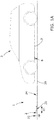
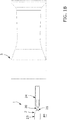
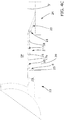
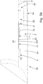
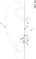
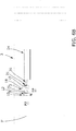
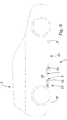
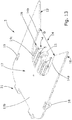
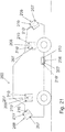
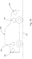
- the figures 1A to 9B show a charging station 1 comprising at least one arm 20, 20' connected to a charger plug 2 by connection means 21, and comprising at least one actuator 22 to move the at least one arm 20, 20'.
- the charging station 1 is characterized in that it comprises a charger plug 2 according to the invention.
- the at least one actuator 22 is arranged to move the at least one arm 20, 20' in rotation and/or in translation.
- the charging station 1 comprises a first arm 20 and a second arm 20', the first arm 20 being connected to the charger plug 2 by the connection means 21, and the second arm 20' being connected to the at least one actuator 22.
- the first arm 20 and the second arm 20' can be orthogonal ( figures 5A , 5B , 9A and 9B ).
- the actuator 22 can move the second arm 20' in translation.
- the translation can be along a vertical direction to move the charger plug 2 in the direction of the bottom 3' of the electric vehicle 3 and/or the translation can be along the bottom 3' of the electric vehicle 3.
- the charging station 1 comprises one arm 20 connected to the charger plug 2 by the connection means 21, and to the at least one actuator 22.
- the actuator 22 can move the arm 20 in translation and/or in rotation.
- the translation can be along a horizontal direction to move the charger plug 2 outside of a first protection housing 23, and/or the rotation can be in a clockwise direction to move the charger plug 2 in the direction of the bottom 3' of the electric vehicle 3 and/or the translation can be along the bottom 3' of the electric vehicle 3.
- the charging station 1 comprises a first protection housing 23 arranged to protect the charger plug 2 and a second protection housing 24 arranged to protect the actuator 22, the first protection housing 23 and the second protection housing 24 being aligned and being separated from one to another by a distance D1.
- the first protection housing 23 is provided to protect the charger plug 2 from the outdoor conditions, when the charging station 1 is not in use ( figures 1A , 1B and 2 ).
- the second protection housing 24 is provided to protect the actuator 22 from outdoor conditions ( figures 1A to 9B ).
- the charging station comprises a single protection housing (not shown) arranged to protect the charger plug 2, the arm 20, 20' and the actuator 22 .
- the charging station 1 comprises at least a power supply system (not shown) to provide electric energy.
- the charging station 1 comprises at least a supply cable (not shown) electrically connected to the charger plug 2, more particularly to the first electric connector 4 and to the power supply system.
- the charging station 1 comprises a cooling system (not shown) to maintain the battery within an acceptable temperature range during a charging session.
- the charging station 1 comprises fluid lines (not shown) connected to the charger plug 2, more particularly to the inlet and outlet fluid connectors and to the cooling system.
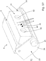
- the figures 1A , 2 , 3A , 3B , 4A , 4B , 4C , 5A , 5B , 6A , 6B , 6C , 7A , 7B , 8 , 9A , 9B , 10 , 11 , 12 , 15 , 16 and 17 show a charging receiver 8 for an electric vehicle 3 suitable for being mounted on the bottom 3' of the electric vehicle 3 and arranged to be coupled with the charger plug 2 according to the invention, the charging receiver 8 comprising at least one second electric connector 7 arranged to be coupled with the first electric connector 4 of the charger plug 2, the second electric connector 7 comprising at least one second electric contact 6 arranged to be electrically coupled with at least one first electric contact 5 of the first electric connector 4 of the charger plug 2, the charging receiver 8 comprising a rotatable protection lid 25 movable in rotation from a first position PI where the protection lid 25 covers the second electric connector 7 to protect the second electric contact 6 and a second position P2 where the protection lid 25 uncovers the second
- the charging receiver 8 is characterized in that the protection lid 25 comprises means 26; 33, 35 for opening the protection lid 25, arranged so that the protection lid 25 tilts from the first position PI to the second position P2 when it cooperates with corresponding means 15; 31, 32 for opening the protection lid 25 of the charger plug 2.
- the protection lid 25 enables to protect the second electric connector 7 from the outdoor conditions, when the charging receiver 8 is not in use.
- These means 26; 33, 35 for opening the protection lid 25 of the charging receiver 8 are provided to automatically open the protection lid 25, so that the protection lid 25 uncovers the second electric connector 7, to enable the connection between the first electric connector 4 and the second electric connector 7.
- the means for opening the protection lid 25 consist of a guiding slot 26 of the protection lid 25 comprising an inclined wall 27, arranged to be coupled with the corresponding means for opening the protection lid 25 of the charger plug 2 consisting of a protrusion 15 projecting from a reception area 14 of the charger plug 2, the guiding slot 26 being arranged so that the protection lid 25 tilts from the first position PI to the second position P2 when the protrusion 15 is engaged with the guiding slot 26.
- This guiding slot 26 is provided to receive the protrusion 15, which can then slide along the inclined wall 27, when the charger plug 2 and the charging receiver 8 are moved relative to each other, in order to rotate the protection lid 25 from the first position PI to the second position P2, in the clockwise direction and then uncover the second electric connector 7.
- a second contact wall 9 of the second electric connector 7 comprises an interlocking area 26' aligned with the guiding slot 26 of the protection lid 25, arranged to be coupled with the protrusion 15 projecting from the reception area 14 of the charger plug 2.
- This interlocking area 26' is provided to receive the protrusion 15 after the connection between the first electric connector 4 and the second electric connector 7.
- the means for opening the protection lid 25 comprise a first protrusion 33 projecting from a first lateral wall 34 of the protection lid 25 and a second protrusion 35 projecting from a second lateral wall 36 of the protection lid 25, the first protrusion 33 and the second protrusion 35 being arranged to cooperate with the corresponding means for opening the protection lid 25 of the charger plug 2 consisting of a first inclined guide rail 31 and a second inclined guide rail 32 so that the protection lid 25 tilts from the first position PI to the second position P2 when the first inclined guide rail 31 leans against and slides on the first protrusion 33 and the second inclined guide rail 32 leans against and slides on the second protrusion 35.
- first protrusion 33 and second protrusion 35 are provided to enable the first inclined guide rail 31 and the second inclined guide rail 32 to slide along them, when the charger plug 2 and charging receiver 8 are moved relative to each other, in order to rotate the protection lid 25 from the first position PI to the second position P2, in the clockwise direction and then uncover the second electric connector 7.
- the protection lid 25 is connected with the second electric connector 7 by return means to enable the automatic return of the protection lid 25 from the second position P2 to the first position P1, when the protrusion 15 is disengaged from the guiding slot 26 or when the first and second inclined guide rails 31, 32 are respectively released from the first and second protrusions 33, 35.
- This return means in a rest position, are provided to maintain the protection lid 25 in the first position PI and to automatically return the protection lid 25 in the first position P1, when the protection lid 25 is deviated from the first position P1.
- this protrusion 15 exerts a force against the return means to stretch them and to rotate the protection lid 25 in the clockwise direction to uncover the second electric connector 7.
- this protrusion 15 no longer exerts this force against the return means, the return means return in their rest position and the protection lid 25 rotates in the anticlockwise direction to cover the second electric connector 7.
- the second female electric connector 7 comprises a plurality of recesses 28, each recess 28 comprises one of the second electric contact 6, each recess 28 comprises a first opening 29 located on the second contact wall 9 for the engagement of the first electric contact 5 of the first male electric connector 4 and a second opening 30.
- This second opening 30 is provided to evacuate the dust which could be located in the recess 28, when the first male electric connector 4 and the second female electric connector 7 connect together. Indeed, the first male electric connector 4 pushes the dust in the direction of the second opening 30, when inserted in the recess 28 through the first opening 29. Thus, the second electric contact 6 can be cleaned during the connection which enables a proper contact between the first electric contact 5 and the second electric contact 6.
- the protection lid 25 is pivotally mounted relative to an axis of the second contact wall 9 of the charging receiver 8.
- the first protrusion 33 and the second protrusion 35 have a cylinder shape ( figures 16 and 17 ).
- the charging receiver 8 comprises an inlet fluid connector 41 and an outlet fluid connector 40.
- the charging receiver 8 is suitable to be electrically connected to the battery of the electric vehicle 3.
- the charging receiver 8 comprises at least one positioning hole 42.
- the second electric connector 7 is a standard connector according to the standard IEC 62196-1/-2/-3.
- the invention also relates to an assembly comprising the charger plug 2 according to the present invention and the charging receiver 8 according to the present invention.
- the first electric connector 4 of the charger plug 2 is in electrical contact with the first electric connector 7 of the charging receiver 8.
- the invention also relates to a method for connecting a charging receiver 8 of an electric vehicle 3 and a charger plug 2 of a charging station 1, the charging station 1 being located on the ground 39 and being suitable to be located underneath the bottom 3' of the electric vehicle 3, the charging station 1 comprising the charger plug 2 which comprises a first electric connector 4, at least one arm 20, 20' connected to the charger plug 2 by connection means 21 and at least an actuator 22 to move the at least one arm 20, 20', the charging receiver 8 being mounted on the bottom 3' of the electric vehicle 3 and comprising a second electric connector 7, the charger plug 2 comprising guiding means 10, 12 comprising a reception area 14 arranged to surround at least partially the charging receiver 8 and arranged to align the first electric connector 4 and the second electric connector 7, when moving the charger plug 2 in the direction of the charging receiver 8 or conversely, method comprising the steps of :
- the movement of the electric vehicle 3 enables to move the charger receiver 8 in the direction of the charger plug 2 while being guided by the bottom 3' of the electric vehicle 3.
- the electric vehicle 1 can be moved in rear motion ( figures 7A and 9A ) or in a forward motion ( figure 8 ) depending of the relative position of the charger plug 2 and the charging receiver 8.
- step B) the movement of the arm 20, 20' enables to move the charger plug 2 in the direction of the charger receiver 8 while being guided by the bottom 3' of the electric vehicle 3.
- this alignment enables a subsequent proper connection, in order to charge the battery of the electric vehicle 3 during a charging session.
- this tilting of the protection lid 25 enables to uncover the second electric connector 7 only during the charging session, to protect them from the outdoor conditions the rest of the time.
- step E the connection between the first electric connector 4 and the second electric contact 7 enable to charge the battery of the electric vehicle with electric energy during the charging session.
- the charger plug 2 is arranged according to the invention described above.
- the charging station 1 is arranged according to the invention described above.
- the charging receiver 8 is arranged according to the invention described above.
- the invention also relates to a charger plug 202, according to a third embodiment, as shown in figures 20 , 22A to 23B , for supplying electric energy from a power supply to a battery of an electric vehicle 203.
- the charger plug 202 comprises at least a first electric connector 204 comprising at least a first electric contact, the first electric connector 204 being arranged to be coupled with a corresponding first electric connector 207 of a charging receiver 208 according to a third embodiment described hereinafter, so that the at least first electric contact being electrically connected with corresponding first electric contact of the second electric connector 207, the charger plug 202 comprising at least a first positioning protrusion 209 arranged to be only mechanically coupled with a first recess 210 of the charging receiver 208.
- the first positioning protrusion 209 is provided to facilitate the alignment of the first electric connector 204 with the second electric connector of the charging receiver 208.
- the charger plug 202 comprises the first positioning protrusion 209 and a second positioning protrusion being arranged to be only mechanically coupled with a second recess 210' of the charging receiver 208.
- the first electric connector 204 comprises a first electric contact, a second electric contact and a third electric contact, the first electric contact being suitable to be electrically connected to a first AC line of the power supply, the second electric contact being suitable to be electrically connected to a neutral line of the power supply, the third electric contact being suitable to be electrically connected to a ground line.
- the charger plug 202 according to this first preferred specificity is arranged to be connected to the charging receiver 208 described hereinafter according to the first preferred specificity.
- the first electric connector 204 comprises a first electric contact, a second electric contact, a third electric contact, a fourth electric contact and a fifth electric contact, the first electric contact being suitable to be electrically connected to a first AC line of the power supply, the second electric contact being suitable to be electrically connected to a second AC line of the power supply, the third electric contact being suitable to be electrically connected to a third AC line of the power supply, the fourth electric contact being suitable to be electrically connected to a neutral line of the power supply, the fifth electric contact being suitable to be electrically connected to a ground line.
- the charger plug 202 according to this second preferred specificity is arranged to be connected to the charging receiver 208 described hereinafter according to the second preferred specificity.
- the first electric connector 204 comprises a first electric contact, a second electric contact and a third electric contact, the first electric contact being suitable to be electrically connected to a first negative DC line of the power supply, the second electric contact being suitable to be electrically connected to a second positive DC line of the power supply and the third electric contact being suitable to be electrically connected to a ground line.
- the charger plug 202 according to this third preferred specificity is arranged to be connected to the charging receiver 208 described hereinafter according to the particularly of the second preferred specificity or to the third preferred specificity.
- the first electric connector 204 comprises a first communication contact and a second communication contact.
- the first electric connector 204 is a standard connector according to the standard IEC 62196-1/-2/-3.
- the charger plug 202 comprises a third protrusion 214 arranged to applied a force F on a protection lid 211 of the charging receiver 208 to move the protection lid 211 from a closed position ( figures 22A and 23A ) to an open position of the protection lid 211 ( figures 22B and 23B ).
- This arrangement enables the automatic opening of the protection lid 211 of the charging receiver 208 when the charger plug 202 is moved in the direction of the charging receiver 208.
- the invention also relates to a charging receiver 208, according to a third embodiment, as shown in figures 19 to 23B , for an electric vehicle 203 comprising a battery.
- the charging receiver 208 is suitable to be electrically connected to the battery and arranged to be coupled with the charger plug 202 according to the third embodiment, the charging receiver 208 comprising at least a first electric connector 207 arranged to be coupled with the first electric connector 204 of the charger plug 202, the second electric connector 207 comprising at least a first electric contact arranged to be electrically coupled with corresponding first electric contact of the first electric connector 204 of the charger plug 202, the charging receiver 208 comprising at least a first recess 210, 210' arranged to be only mechanically coupled with a first positioning protrusion 209 of the charger plug 202, the first recess 210, 210' having a funnel shape.
- This particular funnel shape is provided to facilitate the insertion of the first positioning protrusion 209 and thus to facilitate the alignment of the first electric connector 204 with the second electric connector of the charging receiver 208.
- the charging receiver 208 comprises the first recess 210 and a second recess 210', the second recess 210' being arranged to be only mechanically coupled with a second positioning protrusion of the charger plug 202, the second recess 210' having a funnel shape.
- the second electric connector 207 comprises a first electric contact, a second electric contact and a third electric contact, the first electric contact being suitable to be electrically connected to a first AC line electrically connected to the battery, the second electric contact being suitable to be electrically connected to a neutral line electrically connected to the battery, the third electric contact being suitable to be electrically connected to a ground line.
- the charging receiver 208 according to this first preferred specificity is arranged to be connected to the charger plug 202 according to the first preferred specificity.
- the second electric connector 207 comprises a fourth electric contact and a fifth electric contact, the fourth electric contact being suitable to be electrically connected to a first negative DC line electrically connected to the battery and the fifth electric contact being suitable to be electrically connected to a second positive DC line electrically connected to the battery.
- the charging receiver 208 according to this particularity of the first preferred specificity is arranged to be connected to the charger plug 202 according to the first preferred specificity or to the third preferred specificity.
- the second electric connector 207 comprises a first electric contact, a second electric contact, a third electric contact, a fourth electric contact and a fifth electric contact, the first electric contact being suitable to be electrically connected to a first AC line electrically connected to the battery, the second electric contact being suitable to be electrically connected to a second AC line electrically connected to the battery, the third electric contact being suitable to be electrically connected to a third AC line electrically connected to the battery, the fourth electric contact being suitable to be electrically connected to a neutral line electrically connected to the battery, the fifth electric contact being suitable to be electrically connected to a ground line.
- the charging receiver 208 according to this second preferred specificity is arranged to be connected to the charger plug 202 according to the second preferred specificity.
- the second electric connector 207 comprises a sixth electric contact and an seventh electric contact, the sixth electric contact being suitable to be electrically connected to a first negative DC line electrically connected to the battery and the seventh electric contact being suitable to be electrically connected to a second positive DC line electrically connected to the battery.
- the charging receiver 208 according to this particularity of the second preferred specificity is arranged to be connected to the charger plug 202 according to the second preferred specificity or to the third preferred specificity.
- the second electric connector 207 comprises a first electric contact, a second electric contact and a third electric contact, the first electric contact being suitable to be electrically connected to a first negative DC line electrically connected to the battery, the second electric contact being suitable to be electrically connected to a second positive DC line electrically connected to the battery and the third electric contact being suitable to be electrically connected to a ground line.
- the charging receiver 208 according to this third preferred specificity is arranged to be connected to the charger plug 202 according to the third preferred specificity.
- the second electric connector 207 comprises a first communication contact and a second communication contact.
- the second electric connector 207 is a standard connector according to the standard IEC 62196-1/-2/-3.
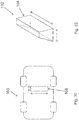
- the charging receiver 208 comprises a protection lid 211 comprising a first part 221a and a second part 211b, the second part 211b being connected with the charging receiver 208 by return means 212, the protection lid 211 being mobile in rotation between a closed position ( figure 22A ), where the first part 211a of the protection lid 211 covers at least the second electric connector 207 and an open position ( figure 22B ), where the first part 211a of the protection lid 211 uncovers at least the second electric connector 207, the return means 212 being arranged to hold the protection lid 211 in the closed position, the protection lid 211 being arranged to move from the closed position to the open position, when a force F is applied on the second part 211b of the protection lid 211.
- the charging receiver 208 comprises a protection lid 211 comprising a first part 211a and a second part 211b, the second part 211b being connected with the charging receiver 208 by return means 212, the protection lid 211 being mobile in translation between a closed position ( figure 23A ), where the first part 211a of the protection lid 211 covers at least the second electric connector 207 and, an open position ( figure 23B ), where an opening 231 of the first part 211a of the protection lid 211 uncovers at least the second electric connector 207, the return means 212 being arranged to hold the protection lid 211 in the closed position, the protection lid 211 being arranged to move from the closed position to the open position when a force F is applied on the second part 211b of the protection lid 211.
- the protection lid 211 is provided to protect the second electric connector 207 from the outdoor conditions.
- this protection lid 211 can be automatically opened, when the charger plug 202 is moved in the direction of the charging receiver 208 and a force F is applied on the second part 211b of the protection lid 211 by the third protrusion 214.
- the invention also relates to a charging station, as shown in figures 24 to 33 .
- the charging station comprises a charger plug 102 according to a fourth embodiment for supplying electric energy to an electric vehicle 103.
- This charger plug 102 comprises a first electric connector 104 comprising a first electric contact 105, a second electric contact 105', a third electric contact 105", the first electric connector 104 being arranged to be coupled with a corresponding second electric connector 107 of a charging receiver 108 according to a fourth embodiment, located underneath the electric vehicle 3, so that the first, second and third electric contacts 105, 105', 105" being electrically connected with corresponding fourth, fifth, sixth electric contacts 106, 106', 106" of the second electric connector 107, the first electric connector 104 having a trapezoidal section and comprising an upper part 109 comprising the first electric contact 105, a first lateral part 110 comprising the second electric contact 105', and a second lateral part 111 comprising the third electric contact 105", the first electric contact
- the charger plug 102 comprises a support 113 bearing the first electric connector 104, the first electric connector 104 being secured to the support 113.
- the charger plug 102 comprises a support 113 bearing the first electric connector 104, the first electric connector 104 being connected to the support 113 by return means 114.
- the upper part 109 comprising the first electric contact 105 is connected to the insulated core 112 by return means 115.
- This return means 115 are provided to ensure the contact of the first electric contact 105 with the corresponding fourth electric contact 106 of the charging receiver 108, which is not necessarily connected to the upper part 126 by return means 127.
- the charging station comprises a protection housing 116 arranged to protect the charger plug 102 and a telescopic arm or a scissor lift connected to the first electric connector 104 movable between a protection position ( figure 30 ), where the first electric connector 104 is enclosed inside the protection housing 116 and an operating position ( figure 31 ), where the first electric connector 104 projects outside the protection housing 116.
- the protection housing 116 comprises a first protection lid 118 arranged to be movable between a closed position and an open position ( figure 31 ), the first protection lid 118 being arranged to move from the closed position to the open position, when the first electric connector 104 of the charger plug 102 leans against the first protection lid 118, and more particularly when the upper part 119 leans against the first protection lid 118.
- This first protection lid 118 is provided to protect the first electric connector 104 from the outdoor conditions. In addition, this first protection lid 118 can be automatically opened, when the charger plug 102 is moved in the direction of the charging receiver 108.
- the first protection lid 118 comprises first cleaning means 119.
- These cleaning means 119 are provided to wipe the first, second and third electric contacts 105, 105', 105" of the first electric connector 104 to clean it from dust and corrosion.
- the cleaning means 119 consist in rough or sharp-edged material, such as hard plastics, metal grater, or brush like material such as metal brush, hard fiber brush.
- the invention relates to a charging receiver 108 according to a fourth embodiment, as shown in figure 24 to 32 , for an electric vehicle 103 suitable for being located underneath the electric vehicle 103 and arranged to be coupled with the charger plug 102 according the fourth embodiment of the charging station, as shown in figures 24 to 32 .
- the charging receiver 108 comprises a second electric connector 107 arranged to be coupled with the first electric connector 104 of the charger plug 102, the second electric connector 107 comprising fourth, fifth, sixth electric contacts 106, 106', 106" arranged to be electrically coupled with corresponding first, second, third electric contacts 105, 105', 105" of the first electric connector 104 of the charger plug 102, the second electric connector 107 comprising a recess 120 where the fourth, fifth, sixth electric contacts 106, 106', 106" are located, the recess 120 comprising an reception opening 121 to allow the insertion of the first electric connector 104 of the charger plug 102.
- the recess 120 has a trapezoidal section, as shown in figures 24 to 27 , 30 , 31 and 33 .
- the recess 120 has a trapezoidal section, comprising a first lateral part 122 comprising the fifth electric contact 106' which is connected to the first lateral part 122 by return means 124 and comprising a second lateral part 123 comprising the sixth electric contact 106" which is connected to the second lateral part 123 by return means 125.
- the return means 124, 125 are provided to ensure the contact respectively of the fifth electric contact 106' with the corresponding second electric contact 105' of the charging plug 102 and of the sixth electric contact 106" with the corresponding third electric contact 105" of the charging plug 102.
- the recess 120 has a trapezoidal section comprising an upper part 126 comprising the fourth electric contact 106 which is connected to the upper part 126 by return means 127.
- the return means 127 are provided to ensure the contact of the fourth electric contact 106 with the corresponding first electric contact 105 of the charging plug 102, which is not necessarily connected to the insulated core 112 by return means 115.
- the recess 120 has a rectangular section, as shown in figures 28 and 29 .
- the recess 120 has a rectangular section, comprising a first lateral part 122 comprising the fifth electric contact 106' which is connected to the first lateral part 122 by return means 124 and comprising a second lateral part 123 comprising the sixth electric contact 106" which is connected to the second lateral part 123 by return means 125.
- the return means 124, 125 are provided to ensure the contact respectively of the fifth electric contact 106' with the corresponding second electric contact 105' of the charging plug 102 and of the sixth electric contact 106" with the corresponding third electric contact 105" of the charging plug 102.
- the recess 120 has a rectangular section comprising an upper part 126 comprising the fourth electric contact 106 which is connected to the upper part 126 by return means 127.
- the return means 127 are provided to ensure the contact of the fourth electric contact 106 with the corresponding first electric contact 105 of the charging plug 102, which is not necessarily connected to the insulated core 112 by return means 115.
- the charging receiver 108 comprises a second protection lid 128 movable from a closed position, where the second protection lid 128 covers the reception opening 121 to protect the second electric connector 107 ( figure 30 ), and an opened position where the second protection lid 128 uncovers the reception opening 121, the second protection lid 128 being connected to the recess 120 by return means so that the second protection lid 128 is arranged to be move from the closed position to the closed position when the first electric connector 104 of the charger plug 102 leans against the second protection lid 128.
- This second protection lid 128 is provided to protect the second electric connector 107 from the outdoor conditions. In addition, this second protection lid 128 can be automatically opened, when the charger plug 102 is moved in the direction of the charging receiver 108.
- the second protection lid 128 or the reception opening 121 comprises second cleaning means 129.
- These second cleaning means 129 are provided to wipe the first, second and third electric contacts 105, 105', 105" of the first electric connector 104 to clean it from dust and corrosion.
- the cleaning means 129 consist in rough or sharp-edged material, such as hard plastics, metal grater, or brush like material such as metal brush, hard fiber brush.
- the charging spot 300 comprises at least one parking spot 301 and a charging station 302, which comprises a charger plug 303 for at least supplying electric energy to a charging receiver 304 of an electric vehicle 305.
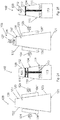
- the charging station 302 comprises a base 306 extending upwardly relative to the ground 307 of the parking spot 301 and a linear actuator 308 comprising a first end 309 mounted on said base 306 and a second end 310, where the charger plug 303 is mounted, said linear actuator 308 being inclined with respect to the base 306 and forming an angle ⁇ with respect to the ground 307, which is equal to the inclination angle of the charging receiver 304 with respect to the ground 307.
- the charging station 302 comprises a secondary control unit (not shown) comprising a secondary communication (not shown) module to communicate with a primary communication module (not shown) of the primary control unit (not shown) of the electric vehicle 305.
- a secondary control unit comprising a secondary communication (not shown) module to communicate with a primary communication module (not shown) of the primary control unit (not shown) of the electric vehicle 305.
- These primary and secondary communication modules are provided to exchange data between the charging spot 300 and the electric vehicle 305.
- the primary communication module and secondary communication module could be any kind of wireless communication means, for instance: a Bluetooth unit or a RFID unit or a NFC unit or a Wi-Fi unit.
- the parking spot 301 comprises at least one reference element (not shown).
- the reference element could be located on the base 306 on which the charger plug 303 is mounted.
- the reference element could be an active distance sensor or a reflector panel/area.
- This reference element is provided to help the primary control unit of the electric vehicle 305 to measure a distance d1, d2 between the charging receiver 304 and the base 306.
- the linear actuator 308 consists of a telescopic arm.
- This charging spot 300 is provided to enable the implementation of a method according to another object according to the invention, described hereinafter.
- the electric vehicle 305 comprises at least one sensor (not shown) and a primary control unit (not shown) comprising a primary communication module (not shown).
- the charging spot 300 comprises at least one parking spot 301 and a charging station 302, which comprises a charger plug 303 for at least supplying electric energy to a charging receiver 304 of an electric vehicle 305.
- the charging station 302 comprises a base 306 extending upwardly relative to the ground 307 of the parking spot 301 and a linear actuator 308 comprising a first end 309 mounted on said base 306 and a second end 310, where the charger plug is mounted, said linear actuator 308 being inclined with respect to the base 306 and forming an angle ⁇ with respect to the ground 307, which is equal to the inclination angle of the charging receiver 304 with respect to the ground 307, the charging station 302 comprising a secondary control unit comprising a secondary communication module to communicate with the primary communication module of the primary control unit of the electric vehicle 305.
- the charger plug 303 is able to cooperate with the charging receiver 304 of the electric vehicle 305.
- the method comprises the steps of:
- the height h1, h2 of the charging receiver 304 may be different.
- figure 35 and 36 show an electric vehicle 305 with a charging receiver 304 having a height h1, which is smaller than the height h2 of the charging receiver 304 of the electric vehicle 305, shown in figures 37 and 38 .
- the angle ⁇ of the charging receiver 304 is standardized, i.e. is independent from the height h1, h2 of the charging receiver 304.
- the primary control unit of the electric vehicle 305 is electrically connected to at least one sensor of the electric vehicle 305.
- the primary control unit is also suitable and provided to control the at least one sensor of the electric vehicle 305 and to collect the data of the sensor, which are representative of the actual distance d1, d2.
- the primary control unit is also suitable and provided to automatically move the electric vehicle 305.
- the primary control unit of the electric vehicle 305 determines the reference distance d1, d2 between the charging receiver 304 and the base 306, knowing the height h1, h2 of the charging receiver 304, the height of the second end 310 and the angle ⁇ .
- the secondary communication module before determining the alignment position, sends data relative to the height of the second end 310 to the primary communication module.
- the secondary control unit of the electric vehicle determines the reference distance d1, d2 between the charging receiver 304 and the base 306, knowing the height h1, h2 of charging receiver 304, the height of the second end 310 and the angle ⁇ .
- the primary communication module before determining the alignment position, sends data relative to the height h1, h2 to the secondary communication module, and after determining the alignment position, the secondary communication module sends data relative to the reference distance d1, d2 to the primary communication module.
- the electric vehicle 308 measures the actual distance d1, d2 between a reference element located on the base 306.
- the method further comprises the step of moving the linear actuator 308 in translation in the direction D of the charging receiver 304, when the electric vehicle 305 is in the alignment position ( figures 36 and 38 ).
- the method further comprises the step of sending a signal from the primary control unit to the secondary control unit, when the electric vehicle 305 is in the alignment position, to trigger the translation of the linear actuator 308.
- the signal consists of an electromagnetic signal provided to communicate wirelessly.
Landscapes
- Engineering & Computer Science (AREA)
- Power Engineering (AREA)
- Transportation (AREA)
- Mechanical Engineering (AREA)
- Charge And Discharge Circuits For Batteries Or The Like (AREA)
- Electric Propulsion And Braking For Vehicles (AREA)
Priority Applications (5)
| Application Number | Priority Date | Filing Date | Title |
|---|---|---|---|
| ES18305428T ES2873941T3 (es) | 2018-04-10 | 2018-04-10 | Enchufe cargador para suministrar energía eléctrica a un vehículo eléctrico, estación de carga que comprende dicho enchufe cargador, receptor de carga para un vehículo eléctrico y método para conectar dicho receptor de carga y dicho enchufe cargador |
| EP18305428.7A EP3552862B1 (de) | 2018-04-10 | 2018-04-10 | Ladestecker zur versorgung eines elektrofahrzeugs mit elektrischer energie, ladestation mit dem ladestecker, ladeempfänger für ein elektrofahrzeug und verfahren zum verbinden des ladeempfängers und des ladesteckers |
| PL18305428T PL3552862T3 (pl) | 2018-04-10 | 2018-04-10 | Wtyczka ładowarki do dostarczania energii elektrycznej do pojazdu elektrycznego, stacja ładowania zawierająca wtyczkę ładowarki, odbiornik ładowarki do pojazdu elektrycznego i sposób łączenia odbiornika ładowarki i wtyczki ładowarki |
| AU2019202467A AU2019202467A1 (en) | 2018-04-10 | 2019-04-09 | Charger plug for supplying electric energy to an electric vehicle, charging station comprising said charger plug, charging receiver for an electric vehicle and method for connecting said charging receiver and said charger plug |
| CN201920483824.7U CN211969196U (zh) | 2018-04-10 | 2019-04-10 | 电动车辆的充电器插头、充电站、充电接收器 |
Applications Claiming Priority (1)
| Application Number | Priority Date | Filing Date | Title |
|---|---|---|---|
| EP18305428.7A EP3552862B1 (de) | 2018-04-10 | 2018-04-10 | Ladestecker zur versorgung eines elektrofahrzeugs mit elektrischer energie, ladestation mit dem ladestecker, ladeempfänger für ein elektrofahrzeug und verfahren zum verbinden des ladeempfängers und des ladesteckers |
Publications (2)
| Publication Number | Publication Date |
|---|---|
| EP3552862A1 true EP3552862A1 (de) | 2019-10-16 |
| EP3552862B1 EP3552862B1 (de) | 2021-03-31 |
Family
ID=61972473
Family Applications (1)
| Application Number | Title | Priority Date | Filing Date |
|---|---|---|---|
| EP18305428.7A Active EP3552862B1 (de) | 2018-04-10 | 2018-04-10 | Ladestecker zur versorgung eines elektrofahrzeugs mit elektrischer energie, ladestation mit dem ladestecker, ladeempfänger für ein elektrofahrzeug und verfahren zum verbinden des ladeempfängers und des ladesteckers |
Country Status (5)
| Country | Link |
|---|---|
| EP (1) | EP3552862B1 (de) |
| CN (1) | CN211969196U (de) |
| AU (1) | AU2019202467A1 (de) |
| ES (1) | ES2873941T3 (de) |
| PL (1) | PL3552862T3 (de) |
Cited By (6)
| Publication number | Priority date | Publication date | Assignee | Title |
|---|---|---|---|---|
| CN111619377A (zh) * | 2020-05-27 | 2020-09-04 | 惠州市英盟科技有限公司 | 一种室外使用时有效防水的电动车大功率充电器及方法 |
| CN112937347A (zh) * | 2019-12-10 | 2021-06-11 | 黑格尔电镀物品股份公司 | 用于从地面充电站向车辆供应电能的连接组件 |
| CN113085613A (zh) * | 2021-04-07 | 2021-07-09 | 张文龙 | 一种基于智能电网的电动汽车充放电设施 |
| JP2022026379A (ja) * | 2020-07-31 | 2022-02-10 | 矢崎総業株式会社 | 車両用充電システム、及び、受電嵌合体 |
| EP3992017A1 (de) * | 2020-10-30 | 2022-05-04 | Continental Engineering Services GmbH | Verfahren zum betreiben eines laderoboters |
| JP2025048689A (ja) * | 2023-09-21 | 2025-04-03 | 矢崎総業株式会社 | 車両用充電装置 |
Families Citing this family (6)
| Publication number | Priority date | Publication date | Assignee | Title |
|---|---|---|---|---|
| JP7559474B2 (ja) * | 2020-09-30 | 2024-10-02 | 新東工業株式会社 | 充電システムおよび情報処理装置 |
| US11427102B2 (en) * | 2020-10-28 | 2022-08-30 | GM Global Technology Operations LLC | System and method of autonomously charging an electric vehicle |
| CN112455260B (zh) * | 2020-11-12 | 2022-07-12 | 武汉合康智能电气有限公司 | 一种充电转换台及充电系统 |
| DE102021209672A1 (de) | 2021-09-02 | 2023-03-02 | Psa Automobiles Sa | Ladedose mit verschließbarer Klappe an einem elektrischen Fahrzeug |
| CN114228542A (zh) * | 2021-12-15 | 2022-03-25 | 广东汉泓医疗科技有限公司 | 一种自动对位电动汽车充电桩 |
| DE102023124300B4 (de) * | 2023-09-08 | 2025-08-28 | Bayerische Motoren Werke Aktiengesellschaft | Ladeanschlusseinheit für ein Elektrofahrzeug und Verfahren zum Herstellen einer elektrischen Steckverbindung mit einer Ladeanschlusseinheit eines Elektrofahrzeugs |
Citations (6)
| Publication number | Priority date | Publication date | Assignee | Title |
|---|---|---|---|---|
| DE102009001080A1 (de) * | 2009-02-23 | 2010-08-26 | Robert Bosch Gmbh | Autonome Ladevorrichtung für Plugln-Hybrid-Fahrzeuge |
| FR2968245A1 (fr) * | 2010-12-02 | 2012-06-08 | Renault Sas | Dispositif de prise en charge escamotable sous plancher d'un vehicule electrique |
| DE102012007713A1 (de) * | 2011-04-20 | 2012-10-25 | SALT AND PEPPER Holding GmbH & Co. KG | Vorrichtung zum elektrischen Laden von elektrisch angetriebenen Straßenfahrzeugen |
| DE102015111099A1 (de) * | 2014-07-24 | 2016-01-28 | Ford Global Technologies, Llc | Berührungsloses Fahrzeugladesystem |
| US20160130851A1 (en) * | 2013-06-20 | 2016-05-12 | Volvo Truck Corporation | Protection arrangement for an electric vehicle |
| US20170096073A1 (en) | 2014-04-29 | 2017-04-06 | Tesla Motors, Inc. | Charging station providing thermal conditioning of electric vehicle during charging session |
-
2018
- 2018-04-10 PL PL18305428T patent/PL3552862T3/pl unknown
- 2018-04-10 ES ES18305428T patent/ES2873941T3/es active Active
- 2018-04-10 EP EP18305428.7A patent/EP3552862B1/de active Active
-
2019
- 2019-04-09 AU AU2019202467A patent/AU2019202467A1/en not_active Abandoned
- 2019-04-10 CN CN201920483824.7U patent/CN211969196U/zh not_active Expired - Fee Related
Patent Citations (6)
| Publication number | Priority date | Publication date | Assignee | Title |
|---|---|---|---|---|
| DE102009001080A1 (de) * | 2009-02-23 | 2010-08-26 | Robert Bosch Gmbh | Autonome Ladevorrichtung für Plugln-Hybrid-Fahrzeuge |
| FR2968245A1 (fr) * | 2010-12-02 | 2012-06-08 | Renault Sas | Dispositif de prise en charge escamotable sous plancher d'un vehicule electrique |
| DE102012007713A1 (de) * | 2011-04-20 | 2012-10-25 | SALT AND PEPPER Holding GmbH & Co. KG | Vorrichtung zum elektrischen Laden von elektrisch angetriebenen Straßenfahrzeugen |
| US20160130851A1 (en) * | 2013-06-20 | 2016-05-12 | Volvo Truck Corporation | Protection arrangement for an electric vehicle |
| US20170096073A1 (en) | 2014-04-29 | 2017-04-06 | Tesla Motors, Inc. | Charging station providing thermal conditioning of electric vehicle during charging session |
| DE102015111099A1 (de) * | 2014-07-24 | 2016-01-28 | Ford Global Technologies, Llc | Berührungsloses Fahrzeugladesystem |
Cited By (11)
| Publication number | Priority date | Publication date | Assignee | Title |
|---|---|---|---|---|
| CN112937347A (zh) * | 2019-12-10 | 2021-06-11 | 黑格尔电镀物品股份公司 | 用于从地面充电站向车辆供应电能的连接组件 |
| EP3835113A1 (de) | 2019-12-10 | 2021-06-16 | Hager-Electro Sas | Verbindungsanordnung zur versorgung eines fahrzeuges mit elektrischer energie von einer bodenladestation |
| CN111619377A (zh) * | 2020-05-27 | 2020-09-04 | 惠州市英盟科技有限公司 | 一种室外使用时有效防水的电动车大功率充电器及方法 |
| CN111619377B (zh) * | 2020-05-27 | 2022-06-17 | 惠州市英盟科技有限公司 | 一种室外使用时有效防水的电动车大功率充电器及方法 |
| JP2022026379A (ja) * | 2020-07-31 | 2022-02-10 | 矢崎総業株式会社 | 車両用充電システム、及び、受電嵌合体 |
| JP7225168B2 (ja) | 2020-07-31 | 2023-02-20 | 矢崎総業株式会社 | 車両用充電システム、及び、受電嵌合体 |
| DE102021119638B4 (de) | 2020-07-31 | 2026-01-22 | Yazaki Corporation | Fahrzeug-Ladesystem und Stromaufnahme-Passkörper |
| EP3992017A1 (de) * | 2020-10-30 | 2022-05-04 | Continental Engineering Services GmbH | Verfahren zum betreiben eines laderoboters |
| CN113085613A (zh) * | 2021-04-07 | 2021-07-09 | 张文龙 | 一种基于智能电网的电动汽车充放电设施 |
| JP2025048689A (ja) * | 2023-09-21 | 2025-04-03 | 矢崎総業株式会社 | 車両用充電装置 |
| JP7840918B2 (ja) | 2023-09-21 | 2026-04-06 | 矢崎総業株式会社 | 車両用充電装置 |
Also Published As
| Publication number | Publication date |
|---|---|
| ES2873941T3 (es) | 2021-11-04 |
| EP3552862B1 (de) | 2021-03-31 |
| AU2019202467A1 (en) | 2019-10-24 |
| PL3552862T3 (pl) | 2021-11-08 |
| CN211969196U (zh) | 2020-11-20 |
Similar Documents
| Publication | Publication Date | Title |
|---|---|---|
| EP3552862B1 (de) | Ladestecker zur versorgung eines elektrofahrzeugs mit elektrischer energie, ladestation mit dem ladestecker, ladeempfänger für ein elektrofahrzeug und verfahren zum verbinden des ladeempfängers und des ladesteckers | |
| US10017062B2 (en) | Electric charging device, electric connection device, system and method for charging a battery of a vehicle | |
| EP3747689B1 (de) | Ladeanschluss für ein mobilgerät | |
| US8579655B2 (en) | Device connector | |
| EP2075880B1 (de) | Hebelsteckverbinder, Steckverbinderanordnung und Verbindungsverfahren | |
| US12447838B2 (en) | Charge port and system for charging of electric vehicle | |
| US20090011616A1 (en) | Widely deployable charging system for vehicles | |
| CN104114401B (zh) | 电缆连接器 | |
| US20210086633A1 (en) | Energy supply arrangement for supplying a motor vehicle with electrical energy via a conductive plug connection and method for operating an energy supply arrangement | |
| CN102376918A (zh) | 将连接器连接于电气设备的连接端子而提供电力的电池组 | |
| CA2146505A1 (en) | Universal electrical connector for receiving dc and ac electrical connectors | |
| CN101807768A (zh) | 结合有信号连接器的电源连接器 | |
| MX2015004971A (es) | Dispositivo de carga para cargar un vehiculo electrico en una estacion de carga. | |
| CN104852225A (zh) | 光电连接组件 | |
| US20220224048A1 (en) | Automatic coupler assembly | |
| CN100377440C (zh) | 连接器主体部件及包括该连接器主体部件的连接器 | |
| CN118369241A (zh) | 用于电动车的充电接口装置 | |
| CN105720485A (zh) | 用于配电板的断路器操作的电气连接开闭器 | |
| EP3552863A1 (de) | Mechanische vorrichtung für eine ladestation | |
| EP3552860A1 (de) | Ladestecker und ladeempfänger | |
| CN117813214A (zh) | 供电设备、车辆和车辆基础设施 | |
| WO2023209537A1 (en) | Charging system for a mobile device | |
| US20180175552A1 (en) | Service plug | |
| CN213637113U (zh) | 一种充电结构及自动行走设备 | |
| US20230344164A1 (en) | Charging system for a mobile device |
Legal Events
| Date | Code | Title | Description |
|---|---|---|---|
| PUAI | Public reference made under article 153(3) epc to a published international application that has entered the european phase |
Free format text: ORIGINAL CODE: 0009012 |
|
| STAA | Information on the status of an ep patent application or granted ep patent |
Free format text: STATUS: THE APPLICATION HAS BEEN PUBLISHED |
|
| AK | Designated contracting states |
Kind code of ref document: A1 Designated state(s): AL AT BE BG CH CY CZ DE DK EE ES FI FR GB GR HR HU IE IS IT LI LT LU LV MC MK MT NL NO PL PT RO RS SE SI SK SM TR |
|
| AX | Request for extension of the european patent |
Extension state: BA ME |
|
| STAA | Information on the status of an ep patent application or granted ep patent |
Free format text: STATUS: REQUEST FOR EXAMINATION WAS MADE |
|
| 17P | Request for examination filed |
Effective date: 20200416 |
|
| RBV | Designated contracting states (corrected) |
Designated state(s): AL AT BE BG CH CY CZ DE DK EE ES FI FR GB GR HR HU IE IS IT LI LT LU LV MC MK MT NL NO PL PT RO RS SE SI SK SM TR |
|
| REG | Reference to a national code |
Ref country code: DE Ref legal event code: R079 Ref document number: 602018014688 Country of ref document: DE Free format text: PREVIOUS MAIN CLASS: B60L0011180000 Ipc: B60L0053140000 |
|
| GRAP | Despatch of communication of intention to grant a patent |
Free format text: ORIGINAL CODE: EPIDOSNIGR1 |
|
| STAA | Information on the status of an ep patent application or granted ep patent |
Free format text: STATUS: GRANT OF PATENT IS INTENDED |
|
| RIC1 | Information provided on ipc code assigned before grant |
Ipc: B60L 53/35 20190101ALI20201019BHEP Ipc: B60L 53/30 20190101ALI20201019BHEP Ipc: B60L 53/14 20190101AFI20201019BHEP Ipc: B60L 53/36 20190101ALI20201019BHEP |
|
| INTG | Intention to grant announced |
Effective date: 20201102 |
|
| RIN1 | Information on inventor provided before grant (corrected) |
Inventor name: SIMON, MICHEL Inventor name: KAUFFMANN, BRUNO Inventor name: HAENEL, FREDERIC Inventor name: REINER, ULRICH Inventor name: SCHMITT, ERWIN Inventor name: KRAEMER, JACQUES Inventor name: MEYER, LOIC |
|
| GRAS | Grant fee paid |
Free format text: ORIGINAL CODE: EPIDOSNIGR3 |
|
| GRAA | (expected) grant |
Free format text: ORIGINAL CODE: 0009210 |
|
| STAA | Information on the status of an ep patent application or granted ep patent |
Free format text: STATUS: THE PATENT HAS BEEN GRANTED |
|
| AK | Designated contracting states |
Kind code of ref document: B1 Designated state(s): AL AT BE BG CH CY CZ DE DK EE ES FI FR GB GR HR HU IE IS IT LI LT LU LV MC MK MT NL NO PL PT RO RS SE SI SK SM TR |
|
| REG | Reference to a national code |
Ref country code: GB Ref legal event code: FG4D Ref country code: CH Ref legal event code: EP |
|
| REG | Reference to a national code |
Ref country code: AT Ref legal event code: REF Ref document number: 1376563 Country of ref document: AT Kind code of ref document: T Effective date: 20210415 |
|
| REG | Reference to a national code |
Ref country code: DE Ref legal event code: R096 Ref document number: 602018014688 Country of ref document: DE |
|
| REG | Reference to a national code |
Ref country code: IE Ref legal event code: FG4D |
|
| REG | Reference to a national code |
Ref country code: NL Ref legal event code: FP |
|
| REG | Reference to a national code |
Ref country code: LT Ref legal event code: MG9D |
|
| PG25 | Lapsed in a contracting state [announced via postgrant information from national office to epo] |
Ref country code: HR Free format text: LAPSE BECAUSE OF FAILURE TO SUBMIT A TRANSLATION OF THE DESCRIPTION OR TO PAY THE FEE WITHIN THE PRESCRIBED TIME-LIMIT Effective date: 20210331 Ref country code: FI Free format text: LAPSE BECAUSE OF FAILURE TO SUBMIT A TRANSLATION OF THE DESCRIPTION OR TO PAY THE FEE WITHIN THE PRESCRIBED TIME-LIMIT Effective date: 20210331 Ref country code: BG Free format text: LAPSE BECAUSE OF FAILURE TO SUBMIT A TRANSLATION OF THE DESCRIPTION OR TO PAY THE FEE WITHIN THE PRESCRIBED TIME-LIMIT Effective date: 20210630 Ref country code: NO Free format text: LAPSE BECAUSE OF FAILURE TO SUBMIT A TRANSLATION OF THE DESCRIPTION OR TO PAY THE FEE WITHIN THE PRESCRIBED TIME-LIMIT Effective date: 20210630 |
|
| PG25 | Lapsed in a contracting state [announced via postgrant information from national office to epo] |
Ref country code: SE Free format text: LAPSE BECAUSE OF FAILURE TO SUBMIT A TRANSLATION OF THE DESCRIPTION OR TO PAY THE FEE WITHIN THE PRESCRIBED TIME-LIMIT Effective date: 20210331 Ref country code: RS Free format text: LAPSE BECAUSE OF FAILURE TO SUBMIT A TRANSLATION OF THE DESCRIPTION OR TO PAY THE FEE WITHIN THE PRESCRIBED TIME-LIMIT Effective date: 20210331 Ref country code: LV Free format text: LAPSE BECAUSE OF FAILURE TO SUBMIT A TRANSLATION OF THE DESCRIPTION OR TO PAY THE FEE WITHIN THE PRESCRIBED TIME-LIMIT Effective date: 20210331 |
|
| PG25 | Lapsed in a contracting state [announced via postgrant information from national office to epo] |
Ref country code: SM Free format text: LAPSE BECAUSE OF FAILURE TO SUBMIT A TRANSLATION OF THE DESCRIPTION OR TO PAY THE FEE WITHIN THE PRESCRIBED TIME-LIMIT Effective date: 20210331 Ref country code: LT Free format text: LAPSE BECAUSE OF FAILURE TO SUBMIT A TRANSLATION OF THE DESCRIPTION OR TO PAY THE FEE WITHIN THE PRESCRIBED TIME-LIMIT Effective date: 20210331 Ref country code: CZ Free format text: LAPSE BECAUSE OF FAILURE TO SUBMIT A TRANSLATION OF THE DESCRIPTION OR TO PAY THE FEE WITHIN THE PRESCRIBED TIME-LIMIT Effective date: 20210331 Ref country code: EE Free format text: LAPSE BECAUSE OF FAILURE TO SUBMIT A TRANSLATION OF THE DESCRIPTION OR TO PAY THE FEE WITHIN THE PRESCRIBED TIME-LIMIT Effective date: 20210331 |
|
| REG | Reference to a national code |
Ref country code: AT Ref legal event code: UEP Ref document number: 1376563 Country of ref document: AT Kind code of ref document: T Effective date: 20210331 |
|
| PG25 | Lapsed in a contracting state [announced via postgrant information from national office to epo] |
Ref country code: IS Free format text: LAPSE BECAUSE OF FAILURE TO SUBMIT A TRANSLATION OF THE DESCRIPTION OR TO PAY THE FEE WITHIN THE PRESCRIBED TIME-LIMIT Effective date: 20210731 Ref country code: SK Free format text: LAPSE BECAUSE OF FAILURE TO SUBMIT A TRANSLATION OF THE DESCRIPTION OR TO PAY THE FEE WITHIN THE PRESCRIBED TIME-LIMIT Effective date: 20210331 Ref country code: RO Free format text: LAPSE BECAUSE OF FAILURE TO SUBMIT A TRANSLATION OF THE DESCRIPTION OR TO PAY THE FEE WITHIN THE PRESCRIBED TIME-LIMIT Effective date: 20210331 Ref country code: PT Free format text: LAPSE BECAUSE OF FAILURE TO SUBMIT A TRANSLATION OF THE DESCRIPTION OR TO PAY THE FEE WITHIN THE PRESCRIBED TIME-LIMIT Effective date: 20210802 |
|
| PG25 | Lapsed in a contracting state [announced via postgrant information from national office to epo] |
Ref country code: LU Free format text: LAPSE BECAUSE OF NON-PAYMENT OF DUE FEES Effective date: 20210410 |
|
| REG | Reference to a national code |
Ref country code: DE Ref legal event code: R097 Ref document number: 602018014688 Country of ref document: DE |
|
| REG | Reference to a national code |
Ref country code: BE Ref legal event code: MM Effective date: 20210430 |
|
| PG25 | Lapsed in a contracting state [announced via postgrant information from national office to epo] |
Ref country code: DK Free format text: LAPSE BECAUSE OF FAILURE TO SUBMIT A TRANSLATION OF THE DESCRIPTION OR TO PAY THE FEE WITHIN THE PRESCRIBED TIME-LIMIT Effective date: 20210331 Ref country code: AL Free format text: LAPSE BECAUSE OF FAILURE TO SUBMIT A TRANSLATION OF THE DESCRIPTION OR TO PAY THE FEE WITHIN THE PRESCRIBED TIME-LIMIT Effective date: 20210331 Ref country code: MC Free format text: LAPSE BECAUSE OF FAILURE TO SUBMIT A TRANSLATION OF THE DESCRIPTION OR TO PAY THE FEE WITHIN THE PRESCRIBED TIME-LIMIT Effective date: 20210331 |
|
| PLBE | No opposition filed within time limit |
Free format text: ORIGINAL CODE: 0009261 |
|
| STAA | Information on the status of an ep patent application or granted ep patent |
Free format text: STATUS: NO OPPOSITION FILED WITHIN TIME LIMIT |
|
| 26N | No opposition filed |
Effective date: 20220104 |
|
| PG25 | Lapsed in a contracting state [announced via postgrant information from national office to epo] |
Ref country code: IE Free format text: LAPSE BECAUSE OF NON-PAYMENT OF DUE FEES Effective date: 20210410 |
|
| PG25 | Lapsed in a contracting state [announced via postgrant information from national office to epo] |
Ref country code: IS Free format text: LAPSE BECAUSE OF FAILURE TO SUBMIT A TRANSLATION OF THE DESCRIPTION OR TO PAY THE FEE WITHIN THE PRESCRIBED TIME-LIMIT Effective date: 20210731 |
|
| PG25 | Lapsed in a contracting state [announced via postgrant information from national office to epo] |
Ref country code: BE Free format text: LAPSE BECAUSE OF NON-PAYMENT OF DUE FEES Effective date: 20210430 |
|
| PGFP | Annual fee paid to national office [announced via postgrant information from national office to epo] |
Ref country code: PL Payment date: 20230321 Year of fee payment: 6 |
|
| PG25 | Lapsed in a contracting state [announced via postgrant information from national office to epo] |
Ref country code: CY Free format text: LAPSE BECAUSE OF FAILURE TO SUBMIT A TRANSLATION OF THE DESCRIPTION OR TO PAY THE FEE WITHIN THE PRESCRIBED TIME-LIMIT Effective date: 20210331 |
|
| P01 | Opt-out of the competence of the unified patent court (upc) registered |
Effective date: 20230606 |
|
| PG25 | Lapsed in a contracting state [announced via postgrant information from national office to epo] |
Ref country code: HU Free format text: LAPSE BECAUSE OF FAILURE TO SUBMIT A TRANSLATION OF THE DESCRIPTION OR TO PAY THE FEE WITHIN THE PRESCRIBED TIME-LIMIT; INVALID AB INITIO Effective date: 20180410 Ref country code: GR Free format text: LAPSE BECAUSE OF FAILURE TO SUBMIT A TRANSLATION OF THE DESCRIPTION OR TO PAY THE FEE WITHIN THE PRESCRIBED TIME-LIMIT Effective date: 20210331 |
|
| PGFP | Annual fee paid to national office [announced via postgrant information from national office to epo] |
Ref country code: ES Payment date: 20230503 Year of fee payment: 6 |
|
| PGFP | Annual fee paid to national office [announced via postgrant information from national office to epo] |
Ref country code: GB Payment date: 20230427 Year of fee payment: 6 |
|
| PG25 | Lapsed in a contracting state [announced via postgrant information from national office to epo] |
Ref country code: MK Free format text: LAPSE BECAUSE OF FAILURE TO SUBMIT A TRANSLATION OF THE DESCRIPTION OR TO PAY THE FEE WITHIN THE PRESCRIBED TIME-LIMIT Effective date: 20210331 |
|
| PG25 | Lapsed in a contracting state [announced via postgrant information from national office to epo] |
Ref country code: TR Free format text: LAPSE BECAUSE OF FAILURE TO SUBMIT A TRANSLATION OF THE DESCRIPTION OR TO PAY THE FEE WITHIN THE PRESCRIBED TIME-LIMIT Effective date: 20210331 |
|
| PG25 | Lapsed in a contracting state [announced via postgrant information from national office to epo] |
Ref country code: MT Free format text: LAPSE BECAUSE OF FAILURE TO SUBMIT A TRANSLATION OF THE DESCRIPTION OR TO PAY THE FEE WITHIN THE PRESCRIBED TIME-LIMIT Effective date: 20210331 |
|
| GBPC | Gb: european patent ceased through non-payment of renewal fee |
Effective date: 20240410 |
|
| PG25 | Lapsed in a contracting state [announced via postgrant information from national office to epo] |
Ref country code: GB Free format text: LAPSE BECAUSE OF NON-PAYMENT OF DUE FEES Effective date: 20240410 |
|
| PG25 | Lapsed in a contracting state [announced via postgrant information from national office to epo] |
Ref country code: GB Free format text: LAPSE BECAUSE OF NON-PAYMENT OF DUE FEES Effective date: 20240410 |
|
| PGFP | Annual fee paid to national office [announced via postgrant information from national office to epo] |
Ref country code: NL Payment date: 20250427 Year of fee payment: 8 |
|
| REG | Reference to a national code |
Ref country code: ES Ref legal event code: FD2A Effective date: 20250526 |
|
| PGFP | Annual fee paid to national office [announced via postgrant information from national office to epo] |
Ref country code: DE Payment date: 20250429 Year of fee payment: 8 |
|
| PG25 | Lapsed in a contracting state [announced via postgrant information from national office to epo] |
Ref country code: ES Free format text: LAPSE BECAUSE OF NON-PAYMENT OF DUE FEES Effective date: 20240411 |
|
| PGFP | Annual fee paid to national office [announced via postgrant information from national office to epo] |
Ref country code: IT Payment date: 20250422 Year of fee payment: 8 |
|
| PGFP | Annual fee paid to national office [announced via postgrant information from national office to epo] |
Ref country code: FR Payment date: 20250425 Year of fee payment: 8 |
|
| PGFP | Annual fee paid to national office [announced via postgrant information from national office to epo] |
Ref country code: CH Payment date: 20250501 Year of fee payment: 8 |
|
| PGFP | Annual fee paid to national office [announced via postgrant information from national office to epo] |
Ref country code: AT Payment date: 20250319 Year of fee payment: 8 |
|
| PG25 | Lapsed in a contracting state [announced via postgrant information from national office to epo] |
Ref country code: PL Free format text: LAPSE BECAUSE OF NON-PAYMENT OF DUE FEES Effective date: 20240410 |