EP3552934A1 - Sattelsystem und fahrrad - Google Patents
Sattelsystem und fahrrad Download PDFInfo
- Publication number
- EP3552934A1 EP3552934A1 EP17875876.9A EP17875876A EP3552934A1 EP 3552934 A1 EP3552934 A1 EP 3552934A1 EP 17875876 A EP17875876 A EP 17875876A EP 3552934 A1 EP3552934 A1 EP 3552934A1
- Authority
- EP
- European Patent Office
- Prior art keywords
- turnover
- saddle
- rotating
- assembly
- mounting
- Prior art date
- Legal status (The legal status is an assumption and is not a legal conclusion. Google has not performed a legal analysis and makes no representation as to the accuracy of the status listed.)
- Granted
Links
Images


Classifications
-
- B—PERFORMING OPERATIONS; TRANSPORTING
- B62—LAND VEHICLES FOR TRAVELLING OTHERWISE THAN ON RAILS
- B62J—CYCLE SADDLES OR SEATS; AUXILIARY DEVICES OR ACCESSORIES SPECIALLY ADAPTED TO CYCLES AND NOT OTHERWISE PROVIDED FOR, e.g. ARTICLE CARRIERS OR CYCLE PROTECTORS
- B62J1/00—Saddles or other seats for cycles; Arrangement thereof; Component parts
- B62J1/08—Frames for saddles; Connections between saddle frames and seat pillars; Seat pillars
-
- B—PERFORMING OPERATIONS; TRANSPORTING
- B62—LAND VEHICLES FOR TRAVELLING OTHERWISE THAN ON RAILS
- B62J—CYCLE SADDLES OR SEATS; AUXILIARY DEVICES OR ACCESSORIES SPECIALLY ADAPTED TO CYCLES AND NOT OTHERWISE PROVIDED FOR, e.g. ARTICLE CARRIERS OR CYCLE PROTECTORS
- B62J1/00—Saddles or other seats for cycles; Arrangement thereof; Component parts
- B62J1/10—Internal adjustment of saddles
-
- B—PERFORMING OPERATIONS; TRANSPORTING
- B62—LAND VEHICLES FOR TRAVELLING OTHERWISE THAN ON RAILS
- B62J—CYCLE SADDLES OR SEATS; AUXILIARY DEVICES OR ACCESSORIES SPECIALLY ADAPTED TO CYCLES AND NOT OTHERWISE PROVIDED FOR, e.g. ARTICLE CARRIERS OR CYCLE PROTECTORS
- B62J1/00—Saddles or other seats for cycles; Arrangement thereof; Component parts
- B62J1/08—Frames for saddles; Connections between saddle frames and seat pillars; Seat pillars
- B62J2001/085—Seat pillars having mechanisms to vary seat height, independently of the cycle frame
Definitions
- the present disclosure relates to a technical field of bicycles, and in particular, to a saddle system and a bicycle.
- Bicycle movement is an easily assigned movement project, and many riders often sit on the saddle for a long time to ride.
- the traditional saddle is fixedly mounted on a vehicle frame, and there are mainly two completed function: In the first case, supporting the body weight of the rider; In the second case, cooperating the stepping schedule of the riding, so as to make the hip complete the rotating formed by the front and rear movement and the left and right movement of the center of gravity on the saddle.
- existing saddle areas are generally small, typically triangular.
- some saddle rotatable bicycles appear.
- the purpose thereof is to allow a rider to ride, and the saddle can rotate follow the hip to reduce friction of the saddle to the hip, thereby reducing injury of the saddle to the hip due to friction.
- the above saddle can rotate basically only in one degree of freedom, however, the hip of the rider during riding is not simply moved in one degree of freedom, so the aforementioned rotatable saddle cannot completely motion follow the hip of the rider, and makes the friction with the hip of the rider.
- Some embodiments of the present disclosure is to provide a saddle system and a bicycle, so as to solve the problem in the related art that a long-time riding bicycle may injure a hip of a rider.
- a saddle system which includes a follower device, which is arranged on a seat rod of a bicycle for mounting a saddle, and the follower device includes a left and right rotating assembly and a left and right turnover assembly which are interconnected.
- the left and right rotating assembly is rotated leftward or rightward with respect to the left and right turnover assembly, so that the saddle rotates leftward or rightward with respect to the seat rod, and the left and right turnover assembly is turned over leftward or rightward with respect to the left and right rotating assembly, so that the saddle is turned over leftward or rightward with respect to the seat rod.
- the saddle system further includes the saddle, the saddle being mounted on the follower device, and the left and right sides of the saddle being respectively provided with a thigh avoidance part.
- a side of the saddle is provided with an avoidance portion for avoiding a private part.
- the left and right rotating assembly is mounted on the seat rod of the bicycle, and the left and right turnover assembly is mounted on the left and right rotating assembly, and the saddle is mounted on the left and right turnover assembly.
- the left and right rotating assembly includes a mounting part and a rotating part, wherein the mounting part is fixedly arranged on the seat rod, the rotating part may be rotatablely mounted on the mounting part leftward or rightward, and the left and right turnover assembly is mounted on the rotating part.
- the left and right turnover assembly includes a connecting part and a turnover part, the connecting part is provided on the rotating part, the turnover part is turned over leftward or rightward and mounted on the connecting part, and the saddle is fixedly connected with the turnover part.
- the left and right rotating assembly further includes a first elastic return member, and the first elastic return member is mounted between the rotating part and the mounting part.
- the left and right turnover assembly further includes a second elastic return member, and the second elastic return member is mounted between the connecting part and the turnover part.
- the rotating part includes a vertical rod and a transverse rod which are connected with each other, wherein the vertical rod is rotatablely mounted on the mounting part, and the left and right turnover assembly is mounted on the transverse rod.
- the transverse rod is movable forward or backward relative to the vertical rod so as to adjust a position.
- an elevation of the transverse rod is adjustably disposed relative to the vertical rod.
- the rotating part further includes a locking connecting member, wherein the locking connecting member is connected between the transverse rod and the vertical rod, and a transverse groove is provided on the transverse rod, wherein the locking connecting member includes a first connecting portion cooperating with the transverse groove; wherein the locking connecting member is provided with a locking state in which the first connecting portion is locked in the transverse groove and an unlocking state in which the first connecting part is allowed to slide with respect to the transverse groove.
- an elevation adjusting portion is provided on the vertical rod
- the locking connecting member further includes a second connecting portion cooperating with the elevation adjusting portion, wherein the locking connecting part adjusts a position of the second connecting portion relative to the elevation adjusting portion to adjust the elevation of the transverse rod, the locking connecting member further locks the second connecting portion on the elevation adjusting portion in the locking state, and the locking connecting member further allows the second connecting portion to move relative to the elevation adjusting portion in the unlocking state.
- the connecting part is turnover-forwardly mounted on the rotating part.
- the rotating part is provided with an accommodating seat, wherein the connecting part is rotatablely mounted in the accommodating seat with respect to the accommodating seat, and the connecting part is connected to a middle front portion of the accommodating seat through a hinge shaft.
- the left and right turnover assembly is used for mounting on a seat tube of a bicycle, wherein the left and right turnover assembly is turned over leftward or rightward with respect to the seat tube, and the left and right turning assembly is mounted on the left and right turnover assembly, and the left and right rotating assembly is rotated leftward or rightward with respect to the left and right turnover assembly, and a mounting portion for mounting the saddle is formed on a top of the left and right rotating assembly.
- the left and right turnover assembly includes: a connecting part for mounting on the seat tube; a turnover part mounted on the connecting part, wherein the turnover part is turned over leftward or rightward with respect to the connecting part, and the left and right rotating assembly is mounted on the turnover part.
- the left and right turnover assembly further includes a turnover transmission part, wherein the turnover transmission part is mounted between the connecting part and the turnover part.
- the left and right rotating assembly includes a rotating part and a rotating transmission part, wherein the rotating part is provided on the turnover part and is rotated leftward or rightward with respect to the turnover part, the rotating transmission part is provided between the rotating part and the turnover part, the mounting portion is formed at a top of the rotating part .
- the left and right turnover assembly further includes a third elastic return member, wherein the third elastic return member is mounted between the connecting part and the turnover part.
- the left and right rotating assembly further includes a fourth elastic return member, wherein the fourth elastic return member is mounted between the rotating member and the turnover member.
- a bicycle comprising a saddle system, wherein the saddle system is the saddle system described above.
- the saddle system when a rider rides, the saddle system can be applied to a bicycle.
- the follower device is arranged on the seat rod of the bicycle, and then the saddle is mounted on the follower device.
- the saddle is rotated leftward or rightward relative to the seat rod, and then the saddle is turned over leftward or rightward relative to the seat rod by the left and right turnover assembly.
- the saddle system of the present embodiment enables the saddle to complete a composite movement of rotation and turnover with the hip of the rider completely, thereby ensuring that the saddle system moves follow completely, reducing friction between the hip and the saddle, and further avoiding damage to the hip of the rider by riding a bicycle for a long time.
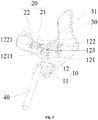
- drawings include the following drawing markers: 10, left and right rotating assembly; 11, mounting part; 12, rotating part; 13, rotating transmission part; 121, vertical rod; 122, transverse rod; 123, locking connecting part; 1211, elevation adjusting portion; 1221, transverse groove; 20, left and right turnover assembly; 21, connecting part; 22, turnover part; 23, turnover transmission part; 30, saddle; 31, thigh avoidance part; 32, avoidance part for avoiding a private part; 40, seat rod; 41, hairspring; 42, spring; 43, spring mounting groove; 44, cooperate protrusion.
- front, rear, left, and right in the text refer to front, rear, left, and right relative to the bicycle during the travel of the bicycle.
- Fig. 1 illustrates a saddle system of embodiment 1, the saddle system includes a follower device arranged on a seat bar 40 of a bicycle for mounting a saddle 30.
- the follower device includes a left and right rotating assembly 10 and a left and right turnover assembly 20 which are interconnected, and the left and right rotating assembly 10 is rotated leftward or rightward with respect to the left and right turnover assembly 20, so that the saddle 30 rotates leftward or rightward with respect to the seat rod 40.
- the left and right turnover assembly 20 is turned over leftward or rightward with respect to left and right rotating assembly 10, so that the saddle 30 is turned over leftward or rightward with respect to seat rod 40.
- the saddle system When a rider rides, the saddle system may be applied to the bicycle.
- the follower device is arranged on the seat rod 40 of the bicycle, and then the saddle 30 is mounted on the follower device.
- a right foot of the rider pedals a pedal if a right foot of the rider pedals a pedal, and a hip of the rider may be inclined to the right involuntatily. Since it is necessary that the rider's foot is extended forward when the rider pedals the pedal, so as to complete a circle movement of the pedal, the hip will rotate rightward involuntatily. Therefore the hip of the rider will eventually perform a composite movement of right inclination and right rotation.
- the saddle 30 may be rotated leftward or rightward relative to the seat rod 40, and then the saddle 30 may be turned over leftward or rightward relative to the seat rod 40 by the left and right turnover assembly 20.
- the saddle system of embodiment 1 enables the saddle 30 to complete a composite movement of rotation and turnover with the hip of the rider, thereby ensuring that the saddle system can move follow completely, reducing friction between the hip and the saddle 30, and further avoiding damage to the hip of the rider by riding a bicycle for a long time.
- the saddle system further includes a saddle 30, where the saddle 30 is mounted on the follower device, and the left and right sides of the saddle 30 are respectively provided with a thigh avoidance part 31.
- the thigh avoidance part 31 can avoid a friction between the thigh and the saddle 30, release the thighs of the rider, and leave the thighs thereof to be supported by the saddle 30, and make the saddle 30 move following with the movement of the hip.
- using said saddle 30 can reduce the friction between the hip and the saddle 30, thereby saving body energy and improving the riding rate.
- the support part at a front part of the traditional saddle 30 presses a perineum of a human body, thereby easily causing the perineum to be insufficient for blood supply and affecting the reproductive health.
- the front side of the saddle 30 is provided with an avoidance part for avoiding a private part 32. In this way, it is possible to avoid the compression of the saddle 30 on the perineum of the human body, and ensure that the reproductive health of the rider is not affected by riding bicycle.
- the left and right rotating assembly 10 is mounted on the seat rod 40 of the bicycle, the left and right turnover assembly 20 is mounted on the left and right rotating assembly 10, and the saddle 30 is mounted on the left and right turnover assembly 20.
- the left and right turnover assembly 20 is mounted on the seat rod 40 of the bicycle, and then the left and right rotating assembly 10 is mounted on the left and right turnover assembly 20.
- the left and right rotating assembly 10 includes a mounting part 11 and a rotation part 12, where the mounting part 11 is fixedly disposed on the seat rod 40, the rotating part 12 may be rotatablely mounted on the mounting part 11 leftward or rightward, and the left and right turnover assembly 20 is mounted on the rotating part 12.
- the mounting part 11 is a sleeve that can be fixedly connected to the seat rod 40
- the rotating part 12 is a rod that can be inserted into the sleeve.
- the left and right rotating assembly 10 further includes a first elastic return member, and the first elastic return member is mounted between the rotating part 12 and the mounting part 11.
- the first elastic return member may help the rotating part 12 returns to an initial position of the rotating part 12, so as to help a rotating angle of the saddle 30 return to a central position of the bicycle.
- a mounting groove for mounting the first elastic return member is provided on a rod member, and the first elastic return member is mounted in the mounting groove.
- a convex portion cooperating with the mounting groove and the first elastic return member is provided in the sleeve.
- the left and right turnover assembly 20 includes a connecting part 21 and a turnover part 22, the connecting part 21 is provided on the rotating part 12, the turnover part 22 is turned over leftward or rightward and mounted on the connecting part 21, and the saddle 30 is fixedly connected with the turnover part 22.
- the connecting part 21 and the rotating part 12 are two separate parts and are connected.
- the connecting part 21 and the rotating part 12 is an integral part.
- the turnover part 22 is a bearing part cooperated with the connecting part 21.
- the left and right turnover assembly 20 further includes a second elastic return member, wherein the second elastic return member is mounted between the connecting part 21 and the turnover part 22.
- the second elastic return member may help the turnover part 22 return to an initial position of the turnover part 22, so as to help the turnover angle of the saddle 30 return to a central position of the bicycle.
- the rotating part 12 includes a vertical rod 121 and a transverse rod 122, the vertical bar 121 is rotatablely mounted on the mounting part 11, and the left and right turnover assembly 20 is mounted on the transverse rod 122.
- the transverse rod 122 is movable forward or backward relative to the vertical rod 121, so as to adjust the front-rear position of the saddle 30 on the bicycle to accommodate the use of different riders.
- an elevation of the transverse rod 122 is adjustably disposed relative to the vertical rod 121.
- the elevation of the saddle 30 is adjusted by adjusting the elevation of the transverse rod 122 relative to the vertical rod 121, so as to bring a head of the saddle 30 upward or downward to apply to the use of different riders.
- the rotating part 12 further includes a locking connecting member 123 connected between the transverse rod 122 and the vertical rod 121.
- the transverse rod 122 is provided with a transverse groove 1221, and the locking connecting member 123 includes a first connecting portion cooperating with the transverse groove 1221.
- the locking connecting member 123 has a locking state in which the first connecting portion is locked in the transverse groove 1221 and an unlocking state in which the first connecting portion is allowed to slide relative to the transverse groove 1221.
- the transverse rod 122 can be conveniently adjusted to move forward or backward by the locking connecting member123.
- an elevation adjusting portion 1211 is provided on the vertical rod 121, and the locking connecting member 123 further includes a second connecting member cooperating with the elevation adjusting portion 1211.
- the locking connector 123 adjusts a position of the second connecting portion relative to the elevation adjusting portion 1211 to adjust the elevation of the transverse rod 122, and the locking connector 123 locks the second connecting portion on the elevation adjusting portion 1211 in the locking state, and the locking connecting member 123 also allows the second connecting portion to move relative to the elevation adjusting portion 1211 in the unlocking state.
- the elevation of the transverse rod 122 can be conveniently adjusted by the locking connecting member 123 and then fixed.
- the elevation adjusting part 1211 is an arc convex portion
- the second connecting portion is an arc clamping groove adapted to the arc convex portion.
- the connecting part 21 is turnover-forwardly mounted on the rotating part 12.
- the connecting part 21 is rotatablely mounted in the accommodating seat with respect to the accommodating seat, and the connecting part 21 is connected to a middle front portion of the accommodating seat through a hinge shaft.
- the left and right rotating assembly 10 includes a mounting part 11 and a rotating part 12.
- the mounting part 11 is for mounting on the seat tube
- the rotating part 12 is mounted on the mounting part 11, and the rotating part 12 is rotatable relative to the mounting part 11, and the left and right turnover assembly 20 is mounted on the rotating part 12.
- the left and right rotating assembly 10 further includes a rotating transmission part 13, and the rotating transmission part 13 is installed between the mounting part 11 and the seat tube. The provision of the rotating transmission part 13 can reduce the frictional force between the mounting part 11 and the rotating part 12, so as to make the rotation of the rotating part 12 more smooth.
- the left and right turnover assembly 20 includes a turnover part 22 and a turnover transmission part 23, a mounting portion is formed on the top of the turnover part 22, and the turnover part 22 is installed on the rotating part 12 with respect to the rotating part 12 turned over leftward or rightward, and the turnover transmission part 23 is installed between the turnover part 22 and the rotating part 12.
- the turnover transmission part 23 is also provided to reduce the frictional force between the connecting part 22 and the rotating part 12, so as to make the turnover part 22 rotate more smoothly.
- the turnover transmission part 23 is also a thrust bearing.
- the turnover part 22 is mounted at both ends of the rotating part 12 by the turnover transmission part 23, and the saddle is mounted on the mounting portions of the two turnover parts 22.
- the turnover transmission part 23 is also a thrust bearing.
- the rotating shaft When the rider is in use, the rotating shaft is mounted on the seat tube of the bicycle, and the rotating part 12 is mounted on the rotating shaft through a thrust bearing.
- the rotating part 12 can rotate leftward or rightward relative to the rotating shaft, and the rotating transmission part 13 can make the rotation of the rotating part 12 more smoothly;
- the turnover part 22 is turned over leftward or rightward relative to the rotating part 12, and the turnover transmission part 23 makes the turnover part 22 rotate more smoothly.
- the saddle can complete the composite movement of rotation and turnover with the hip of the rider, so as to ensure that the saddle system can move follow completely and reduce the friction between the hip and the saddle, thereby avoiding damage to the hip of the rider by riding the bicycle for a long time.
- the left and right rotating assembly 10 further includes a first elastic return member installed between the mounting part 11 and the rotating part 12.
- the first elastic return member can make the rotating part 12 returns to an initial position of the rotating part 12, so as to help the turnover angle of the saddle return to the center position of the bicycle.
- the left and right turnover assembly 20 further includes a second elastic return member installed between the turnover part 22 and the rotating part 12. The second elastic return member can help the turnover part 22 return to an initial position of the turnover part 22, so as to help the saddle return to a central position of the bicycle.
- the first elastic return member and the second elastic return member can automatically make the saddle after the saddle deviating from the central position of the bicycle return to an initial position of the saddle, which can help the hip of the rider to return to an initial position of the hip after rotation, thereby reducing the energy loss of the rider.
- Fig. 4 shows a third embodiment of a saddle system according to the present disclosure
- the saddle system includes a follower device
- the follower device includes a left and right rotating assembly 10 for mounting on a seat tube of a bicycle, and the left and right rotating assembly 10 is rotated leftward or rightward relative to the seat tube.
- the left and right turnover assembly 20 is mounted on the left and right rotating assembly 10; the left and right turnover assembly 20 can be turned over leftward or rightward with respect to the left and right rotating assembly 10; and a mounting portion for mounting a saddle is formed on a top of the left and right turnover assembly 20.
- the left and right rotating assembly 10 includes a mounting part 11 and a rotating part 12.
- the mounting part 11 is for mounting on the seat tube
- the rotating part 12 is mounted on the mounting part 11, and the rotating part 12 is rotatable relative to the mounting part 11, and the left and right turnover assembly 20 is mounted on the rotating part 12.
- the left and right rotating assembly 10 further includes a rotating transmission part 13, and the rotating transmission part 13 is installed between the mounting part 11 and the seat tube.
- the left and right turnover assembly 20 includes a turnover part 22 and a turnover transmission part 23, in which the mounting portion is formed on a top of the turnover part 22, the turnover part 22 can be turned over leftward or rightward with respect to the rotating part 12 and mounted on the rotating part 12, and the turnover transmission part 23 is mounted between the turnover part 22 and the turnover part 12.
- the number of the turnover part 22 is two
- the number of the turnover transmission part 23 is also two
- the two turnover parts 22 are mounted at two ends of the rotating part 12 respectively
- the two turnover transmission parts 23 are mounted between two turnover parts 22 and two ends of the rotating part 12 respectively.
- the mounting part 11 in embodiment 2 includes a base and a mounting sleeve
- the base is used for fixedly connecting with the seat tube
- the mounting sleeve is arranged on the base
- the rotating part 12 is of T-shaped
- the rotating part 12 includes a vertical shaft and a transverse shaft which are interconnected.
- the vertical shaft is rotatablely mounted in the mounting sleeve
- the two turnover parts 22 are respectively provided at two ends of the rotating part 12 in a sleeving manner.
- the base When the rider rides, the base is fixedly mounted on the seat tube of the bicycle, the turnover transmission part 23 is mounted in the mounting sleeve, and then the vertical shaft of the rotating part 12 is inserted into the mounting sleeve to cooperate with the turnover transmission part 23. Thereafter, the two turnover transmission parts 23 are mounted at both ends of the second rotating part, and the two turnover transmission parts 22 are provided at both ends of the second rotating part in a sleeving manner to cooperate with the turnover transmission parts 23.
- the rotating part 12 When the rider rides, the rotating part 12 can rotate leftward or rightward relative to the mounting sleeve, and the rotating transmission part 13 can make the rotation of the rotating part 12 more smoothly; the turnover part 22 can be turned over leftward or rightward relative to the rotating part 12, and the turnover transmission part 23 can make rotation of the turnover part 22 more smoothly.
- the saddle can complete the composite movement of rotation and turnover with the hip of the riders, so as to ensure that the saddle system can move following completely and reduce the friction between the hip and the saddle, thereby avoiding damage to the hip of the rider by riding the bicycle for a long time.
- the left and right rotating assembly 10 further includes a first elastic return member installed between the mounting part 11 and the rotating part 12.
- the first elastic return member may make the rotating part 12 return to an initial position of the rotating part 12 to help the saddle return to the center position of the bicycle.
- the left and right turnover assembly 20 further includes a second elastic return member installed between the turnover part 22 and the rotating part 12. The second elastic return member may help the turnover part 22 return to an initial position of the rotating part 22 to help the saddle return to a central position of the bicycle.
- the first elastic return member and the second elastic return member can automatically make the saddle return to an initial position of the saddle after deviating from the central position of the bicycle, which may help the hip of the rider to return to an initial position of the hip after rotation, thereby reducing the energy loss of the rider.
- Fig. 5 illustrates a fourth embodiment of a saddle system according to the present disclosure
- the saddle system includes a follower device
- the follower device includes a left and right rotating assembly 10 for mounting on a seat tube of a bicycle, and the left and right rotating assembly 10 can be rotated leftward or rightward with respect to the seat tube.
- the follower device includes a left and right turnover assembly 20 mounted on the left and right rotating assembly 10; the left and right turnover assembly 20 can be turned over leftward or rightward with respect to the left and right rotating assembly 10; and a mounting portion for mounting a saddle is formed on a top of the left and right turnover assembly 20.
- the left and right rotating assembly 10 includes a mounting part 11 and a rotating part 12.
- the mounting part 11 is for mounting on the seat tube
- the rotating part 12 is mounted on the mounting part 11, and the rotating part 12 is rotatable relative to the mounting part 11, and the left and right turnover assembly 20 is mounted on the rotating part 12.
- the left and right rotating assembly 10 further includes a rotating transmission part 13, and the rotating transmission part 13 is installed between the mounting part 11 and the seat tube.
- the left and right turnover assembly 20 includes a turnover part 22 and a turnover transmission part 23, a mounting portion is formed on a top of the turnover part 22, the turnover part 22 can be turned leftward or rightward with respect to the rotating part 12 and mounted on the rotating part 12, and the turnover transmission part 23 is mounted between the turnover part 22 and the rotating part 12.
- the number of the turnover part 22 is two
- the number of the turnover transmission part 23 is also two
- the two turnover parts 22 are respectively mounted at two ends of the rotating part 12, and the two turnover transmission parts 23 are respectively mounted between two turnover parts 22 and two ends of the rotating part 12.
- the mounting part 11 includes a base and a mounting protrusion
- the base is used for fixedly connecting with the base tube
- the mounting protrusion is provided on the base.
- the rotating part 12 is of T-shaped and includes a vertical shaft and a transverse shaft connected with the vertical shaft, and a bottom end of the vertical shaft forms a lower sleeve structure
- the lower sleeve structure is provided on the mounting protrusion in a sleeving manner
- two ends of the transverse shaft respectively form a front sleeve structure and a rear sleeve structure
- the two turnover parts 22 are snap-fitted into the front sleeve structure and the rear sleeve structure respectively.
- the base When the rider rides, the base is fixedly mounted on the seat tube of the bicycle, the turnover transmission part 23 is mounted on the mounting protrusion, and then the vertical shaft of the rotating part 12 is provided on the mounting protrusion in a sleeving manner and cooperates with the turnover transmission part 23. Thereafter, the two turnover transmission parts 23 are mounted in both ends of the transverse shaft of the second rotating part, and the two turnover parts 22 are inserted into both ends of the transverse shaft of the second rotating part to cooperate with the turnover transmission parts 23.
- the rotating part 12 When the rider rides, the rotating part 12 can rotate leftward or rightward with respect to the mounting protrusion, and the rotating transmission part 13 can make the rotation of the rotating part 12 more smoothly; the turnover part 22 can be turned over leftward or rightward relative to the rotating part 12, and the turnover transmission part 23 can make the rotation of the turnover part 22 more smoothly.
- the saddle can complete the composite movement of rotation and turnover with the hip of the riders, so as to ensure that the saddle system can move follow completely and reduce the friction between the hip and the saddle, thereby avoiding damage to the hip of the rider by riding the bicycle for a long time.
- the seat system of the present disclosure further provides a fifth embodiment.
- the left and right turnover assembly 20 is mounted on a seat tube of the bicycle, and the left and right turnover assembly 20 can be turned over leftward or rightward with respect to the seat tube.
- the left and right rotating assembly 10 is mounted on the left and right turnover assembly 20, and the left and right rotating assembly 10 can be rotated leftward or rightward with respect to the left and right turnover assembly 20, and a mounting portion for mounting a saddle is formed on a top of the left and right rotating assembly 10.
- the saddle can be turned over leftward or rightward relative to the seat tube, and then the left and right rotating assembly 10 can be used to make the saddle rotate leftward or rightward relative to the seat tube.
- the saddle system of embodiment 5 enables the saddle to complete a composite movement of rotation and turnover with the hip of the rider, thereby ensuring that the saddle system can move follow completely, reducing friction between the hip and the saddle, and thus avoiding damage to the hip of the rider by riding the bicycle for a long time.
- the left and right turnover assembly 20 includes a connecting part 21 and a turnover part 22.
- the connecting part 21 is mounted on the seat tube; the turnover part 22 is mounted on the connecting part 21, and the turnover part 22 may be turned over leftward or rightward with respect to the connecting part 21, and the left and right rotating assembly 10 is mounted on the turnover part 22.
- the connecting part 21 can be connected to the seat tube through a connecting part, or directly welded to the seat tube.
- the left and right turnover assembly 20 further include a turnover transmission part 23 installed between the connecting part 21 and the turnover part 22.
- the turnover transmission part 23 can reduce the frictional force between the connecting part 21 and the turnover part 22 to make the turnover part 22 rotate more smoothly.
- the left and right rotating assembly 10 includes a rotating part 12 and a rotating transmission part 13, the rotating part 12 is arranged on the turnover part 22 and can rotate leftward or rightward with respect to the turnover part 22.
- the rotating transmission part 13 is disposed between the rotating part 12 and the turnover part 22, and a mounting portion is formed at the top of the rotating part 12.
- the rotating transmission part 13 is also provided to reduce the frictional force between the rotating part 12 and the turnover part 22 to make the rotation of the rotating part 12 more smoothly.
- the turnover part 22 is of T-shaped, and includes a transverse shaft and a longitudinal shaft connected thereto.
- the number of the connecting part 21 and the turnover transmission part 23 are both two, and the two connecting parts 21 are mounted on the seat tube at intervals.
- the two ends of the transverse shaft are respectively mounted on the two connecting parts 21 through two turnover transmission parts 23, and the rotating parts 12 are mounted on the free end of the longitudinal shaft through the rotating transmission parts 13.
- the two turnover transmission parts 23 are firstly mounted on the two connecting parts 21, and then the two ends of the transmission shaft of the turnover part 22 are mounted on the connecting parts 21 to cooperate with the turnover transmission parts 23. Thereafter, the rotating transmission part 13 is mounted on the free end of the longitudinal shaft of the turnover part 22, and finally the rotating part 12 is mounted on the turnover part 22 to cooperate with the rotating transmission part 13.
- the connecting part 21 is a common bearing
- the turnover part 22 is a thrust bearing.
- the turnover part 22 can be turned over leftward or rightward with respect to the connecting part 21, and the connecting part 21 makes the rotation of the turnover part 22 more smoothly;
- the rotating part 12 can be rotated leftward or rightward relative to the turnover part 22, and the rotating transmission part 13 makes the rotation of the rotating part 12 more smoothly.
- the saddle can complete the composite movement of rotation and turnover with the hip of the rider, so as to ensure that the saddle system can move following completely and reduce the friction between the hip and the saddle, thereby avoiding damage to the hip of the rider by riding the bicycle for a long time.
- the left and right turnover assembly 20 further includes a third elastic return member installed between the connecting part 21 and the turnover part 22.
- the third elastic return member can make the turnover part 22 return to an initial position of turnover part 22 , so as to help the saddle turnover back to the center position of the bicycle.
- the left and right rotating assembly 10 further includes a fourth elastic return member mounted between the rotating part 12 and the rotating transmission part 13. The fourth elastic return member may help the rotating part 12 return to an initial position of the rotating part 12, so as to help the saddle rotate back to the center position of the bicycle.
- the third elastic return member and the fourth elastic return member may automatically make the saddle return to an initial position of the saddle after deviating from the central position of the bicycle, which may help the hip of the rider return to an initial position of the hip after rotation, thereby reducing the energy loss of the rider.
- the mounting manner of the first return member, the second return member, the third elastic return member and the fourth elastic return member can be as shown in Fig. 8 , or as shown in Fig. 9 .
- the two relatively rotating parts are returned to their initial position by the hairspring 41.
- a spring 42 is installed between the two relatively rotating parts, and the two relatively rotating parts are returned to their initial position by the restoring force of the spring 42.
- a spring mounting groove 43 is provided on one partpart, and a cooperate protrusion 44 is provided on the other part , and two springs are respectively mounted between the spring mounting groove 43 and the cooperate protrusion 44, so as to achieve the effect of returning to their initial position of the two relatively rotating parts.
- the disclosure also provides a bicycle comprising the saddle system described above.
- the saddle can complete the composite movement of rotation and turnover completely with the hip of the rider, thereby ensuring that the saddle system can be completely follow, reducing the friction between the hip and the saddle, and further avoiding damage to the hip of the rider due to long-time riding of the bicycle.
Landscapes
- Engineering & Computer Science (AREA)
- Mechanical Engineering (AREA)
- Motorcycle And Bicycle Frame (AREA)
- Automatic Cycles, And Cycles In General (AREA)
Applications Claiming Priority (4)
| Application Number | Priority Date | Filing Date | Title |
|---|---|---|---|
| CN201621311864.6U CN206288129U (zh) | 2016-12-01 | 2016-12-01 | 鞍座系统及自行车 |
| CN201621311863.1U CN206288128U (zh) | 2016-12-01 | 2016-12-01 | 鞍座系统及自行车 |
| CN201621311862.7U CN206288127U (zh) | 2016-12-01 | 2016-12-01 | 鞍座系统 |
| PCT/CN2017/112107 WO2018099298A1 (zh) | 2016-12-01 | 2017-11-21 | 鞍座系统及自行车 |
Publications (4)
| Publication Number | Publication Date |
|---|---|
| EP3552934A1 true EP3552934A1 (de) | 2019-10-16 |
| EP3552934A4 EP3552934A4 (de) | 2021-01-13 |
| EP3552934C0 EP3552934C0 (de) | 2024-01-24 |
| EP3552934B1 EP3552934B1 (de) | 2024-01-24 |
Family
ID=62241184
Family Applications (1)
| Application Number | Title | Priority Date | Filing Date |
|---|---|---|---|
| EP17875876.9A Active EP3552934B1 (de) | 2016-12-01 | 2017-11-21 | Sattelsystem und fahrrad |
Country Status (3)
| Country | Link |
|---|---|
| US (1) | US11124255B2 (de) |
| EP (1) | EP3552934B1 (de) |
| WO (1) | WO2018099298A1 (de) |
Family Cites Families (28)
| Publication number | Priority date | Publication date | Assignee | Title |
|---|---|---|---|---|
| US605151A (en) * | 1898-06-07 | Joseph franklin twist | ||
| US619768A (en) * | 1899-02-21 | lewis | ||
| DE827008C (de) * | 1949-11-01 | 1952-01-07 | Willy Messerschmitt Dr Ing | Sattel fuer Fahrraeder o. dgl. |
| US4877286A (en) * | 1987-05-27 | 1989-10-31 | J. B. Two Corporation | Adjustable width bicycle seat |
| CA2053424A1 (en) | 1990-06-25 | 1991-12-26 | Richard A. Denisar | Bicycle seat |
| FR2723905B1 (fr) | 1994-08-23 | 1997-01-24 | Proust Daniel | Selle ergonomique a suppression de frottements et contraintes |
| US6116683A (en) * | 1997-05-19 | 2000-09-12 | Maier; Dillon | Bicycle touring seat |
| US5911474A (en) * | 1998-02-07 | 1999-06-15 | Lee; Ralph | Bicycle seat |
| US6056356A (en) * | 1998-08-17 | 2000-05-02 | Unger, Jr.; Joseph F. | Cycle seat |
| US6402235B1 (en) * | 1998-09-04 | 2002-06-11 | Rodger B. Letendre | Split bicycle seat |
| US5988740A (en) * | 1998-11-06 | 1999-11-23 | Caraballo; Abelardo | Bicycle seat |
| DE20100412U1 (de) | 2001-01-11 | 2001-06-13 | Postel, Peter, Dipl.-Ing., 82467 Garmisch-Partenkirchen | Fahrradsattel mit zwei unabhängig voneinander beweglichen Sitzteilen |
| GB0110369D0 (en) * | 2001-04-27 | 2001-06-20 | Catling Jon | Articulated bicycle seat |
| US6786542B1 (en) * | 2001-10-31 | 2004-09-07 | Joseph Nuzzarello | Articulating adjustable resistance suspension seat |
| DE20215136U1 (de) | 2002-10-02 | 2003-02-13 | Melnikovic, Vladimir, 72076 Tübingen | Fahrradsattel |
| US6761400B2 (en) * | 2002-10-05 | 2004-07-13 | Richard Hobson | Bicycle seat |
| US20050093348A1 (en) * | 2003-10-30 | 2005-05-05 | Heady Steven R. | "Butt-saver" TM |
| CN2806271Y (zh) | 2005-01-06 | 2006-08-16 | 周铜 | 防疲劳新型自行车座椅 |
| US7494181B2 (en) * | 2006-09-05 | 2009-02-24 | Samuel Tucker | Bicycle seat |
| WO2009029115A1 (en) * | 2007-08-31 | 2009-03-05 | Petrie Thomas H | Bicycle components mounting methods and apparatus |
| US8998314B2 (en) * | 2012-11-13 | 2015-04-07 | Balanced Bicycle Seats Llc | Bicycle seat |
| GB2524471A (en) * | 2014-02-20 | 2015-09-30 | John Davis | A bicycle saddle |
| DE102015122778A1 (de) * | 2015-12-23 | 2017-06-29 | Heinz Kettler Gmbh & Co. Kg | Sattelvorrichtung für ein Trainingsgerät |
| US20170355409A1 (en) * | 2016-06-14 | 2017-12-14 | Salvatore Deiana | Pivoting bicycle seat |
| CN206288127U (zh) | 2016-12-01 | 2017-06-30 | 李文军 | 鞍座系统 |
| CN206288128U (zh) | 2016-12-01 | 2017-06-30 | 李文军 | 鞍座系统及自行车 |
| CN206288129U (zh) | 2016-12-01 | 2017-06-30 | 李文军 | 鞍座系统及自行车 |
| CN106741353B (zh) | 2016-12-01 | 2022-09-27 | 李文军 | 鞍座系统及自行车 |
-
2017
- 2017-11-21 EP EP17875876.9A patent/EP3552934B1/de active Active
- 2017-11-21 US US16/465,580 patent/US11124255B2/en active Active
- 2017-11-21 WO PCT/CN2017/112107 patent/WO2018099298A1/zh not_active Ceased
Also Published As
| Publication number | Publication date |
|---|---|
| US11124255B2 (en) | 2021-09-21 |
| EP3552934C0 (de) | 2024-01-24 |
| US20190308682A1 (en) | 2019-10-10 |
| WO2018099298A1 (zh) | 2018-06-07 |
| EP3552934A4 (de) | 2021-01-13 |
| EP3552934B1 (de) | 2024-01-24 |
Similar Documents
| Publication | Publication Date | Title |
|---|---|---|
| US9321496B2 (en) | Bicycle seat | |
| US9033356B2 (en) | Shilly-car | |
| US20120242121A1 (en) | Pivoting Nose-Less Bicycle Seat | |
| JP2005132241A (ja) | シートスライド装置 | |
| US11124255B2 (en) | Saddle system and bicycle | |
| KR20150084508A (ko) | 자전거 안장 | |
| EP2921341B1 (de) | Einstellbarer Seitenhalter | |
| US20040245744A1 (en) | Adjustable vehicle | |
| CN206983794U (zh) | 儿童安全座椅 | |
| CN104354627A (zh) | 一种汽车座椅的脚托装置 | |
| ATE469815T1 (de) | Sattel für fahrrad | |
| CA2887680A1 (en) | Bicycle seat | |
| CN106741353B (zh) | 鞍座系统及自行车 | |
| JP6631790B2 (ja) | 複輪車両 | |
| CN206288129U (zh) | 鞍座系统及自行车 | |
| JPH05112269A (ja) | ペダル操作装置用のシート | |
| CN202279004U (zh) | 一种带轮儿童汽车安全椅 | |
| KR20110083000A (ko) | 자전거용 안장 | |
| CN109562803B (zh) | 自行车座椅和脚踏车 | |
| CN108349559B (zh) | 脚踏车座垫 | |
| CN221438202U (zh) | 一种座椅架和电动三轮车 | |
| CN102848943B (zh) | 一种带轮儿童汽车安全椅 | |
| KR102491901B1 (ko) | 조절기능을 가지는 자전거 안장 | |
| KR20250052146A (ko) | 자전거 안장 | |
| JPS633530Y2 (de) |
Legal Events
| Date | Code | Title | Description |
|---|---|---|---|
| STAA | Information on the status of an ep patent application or granted ep patent |
Free format text: STATUS: THE INTERNATIONAL PUBLICATION HAS BEEN MADE |
|
| PUAI | Public reference made under article 153(3) epc to a published international application that has entered the european phase |
Free format text: ORIGINAL CODE: 0009012 |
|
| STAA | Information on the status of an ep patent application or granted ep patent |
Free format text: STATUS: REQUEST FOR EXAMINATION WAS MADE |
|
| 17P | Request for examination filed |
Effective date: 20190628 |
|
| AK | Designated contracting states |
Kind code of ref document: A1 Designated state(s): AL AT BE BG CH CY CZ DE DK EE ES FI FR GB GR HR HU IE IS IT LI LT LU LV MC MK MT NL NO PL PT RO RS SE SI SK SM TR |
|
| AX | Request for extension of the european patent |
Extension state: BA ME |
|
| DAV | Request for validation of the european patent (deleted) | ||
| DAX | Request for extension of the european patent (deleted) | ||
| A4 | Supplementary search report drawn up and despatched |
Effective date: 20201214 |
|
| RIC1 | Information provided on ipc code assigned before grant |
Ipc: B62J 1/10 20060101ALI20201208BHEP Ipc: B62J 1/08 20060101AFI20201208BHEP |
|
| STAA | Information on the status of an ep patent application or granted ep patent |
Free format text: STATUS: EXAMINATION IS IN PROGRESS |
|
| 17Q | First examination report despatched |
Effective date: 20221222 |
|
| GRAP | Despatch of communication of intention to grant a patent |
Free format text: ORIGINAL CODE: EPIDOSNIGR1 |
|
| STAA | Information on the status of an ep patent application or granted ep patent |
Free format text: STATUS: GRANT OF PATENT IS INTENDED |
|
| INTG | Intention to grant announced |
Effective date: 20230823 |
|
| GRAS | Grant fee paid |
Free format text: ORIGINAL CODE: EPIDOSNIGR3 |
|
| GRAA | (expected) grant |
Free format text: ORIGINAL CODE: 0009210 |
|
| STAA | Information on the status of an ep patent application or granted ep patent |
Free format text: STATUS: THE PATENT HAS BEEN GRANTED |
|
| AK | Designated contracting states |
Kind code of ref document: B1 Designated state(s): AL AT BE BG CH CY CZ DE DK EE ES FI FR GB GR HR HU IE IS IT LI LT LU LV MC MK MT NL NO PL PT RO RS SE SI SK SM TR |
|
| REG | Reference to a national code |
Ref country code: GB Ref legal event code: FG4D |
|
| REG | Reference to a national code |
Ref country code: CH Ref legal event code: EP |
|
| REG | Reference to a national code |
Ref country code: IE Ref legal event code: FG4D |
|
| REG | Reference to a national code |
Ref country code: DE Ref legal event code: R096 Ref document number: 602017078793 Country of ref document: DE |
|
| U01 | Request for unitary effect filed |
Effective date: 20240213 |
|
| U07 | Unitary effect registered |
Designated state(s): AT BE BG DE DK EE FI FR IT LT LU LV MT NL PT SE SI Effective date: 20240222 |
|
| PG25 | Lapsed in a contracting state [announced via postgrant information from national office to epo] |
Ref country code: IS Free format text: LAPSE BECAUSE OF FAILURE TO SUBMIT A TRANSLATION OF THE DESCRIPTION OR TO PAY THE FEE WITHIN THE PRESCRIBED TIME-LIMIT Effective date: 20240524 |
|
| PG25 | Lapsed in a contracting state [announced via postgrant information from national office to epo] |
Ref country code: GR Free format text: LAPSE BECAUSE OF FAILURE TO SUBMIT A TRANSLATION OF THE DESCRIPTION OR TO PAY THE FEE WITHIN THE PRESCRIBED TIME-LIMIT Effective date: 20240425 |
|
| PG25 | Lapsed in a contracting state [announced via postgrant information from national office to epo] |
Ref country code: RS Free format text: LAPSE BECAUSE OF FAILURE TO SUBMIT A TRANSLATION OF THE DESCRIPTION OR TO PAY THE FEE WITHIN THE PRESCRIBED TIME-LIMIT Effective date: 20240424 Ref country code: HR Free format text: LAPSE BECAUSE OF FAILURE TO SUBMIT A TRANSLATION OF THE DESCRIPTION OR TO PAY THE FEE WITHIN THE PRESCRIBED TIME-LIMIT Effective date: 20240124 |
|
| PG25 | Lapsed in a contracting state [announced via postgrant information from national office to epo] |
Ref country code: ES Free format text: LAPSE BECAUSE OF FAILURE TO SUBMIT A TRANSLATION OF THE DESCRIPTION OR TO PAY THE FEE WITHIN THE PRESCRIBED TIME-LIMIT Effective date: 20240124 |
|
| PG25 | Lapsed in a contracting state [announced via postgrant information from national office to epo] |
Ref country code: RS Free format text: LAPSE BECAUSE OF FAILURE TO SUBMIT A TRANSLATION OF THE DESCRIPTION OR TO PAY THE FEE WITHIN THE PRESCRIBED TIME-LIMIT Effective date: 20240424 Ref country code: NO Free format text: LAPSE BECAUSE OF FAILURE TO SUBMIT A TRANSLATION OF THE DESCRIPTION OR TO PAY THE FEE WITHIN THE PRESCRIBED TIME-LIMIT Effective date: 20240424 Ref country code: IS Free format text: LAPSE BECAUSE OF FAILURE TO SUBMIT A TRANSLATION OF THE DESCRIPTION OR TO PAY THE FEE WITHIN THE PRESCRIBED TIME-LIMIT Effective date: 20240524 Ref country code: HR Free format text: LAPSE BECAUSE OF FAILURE TO SUBMIT A TRANSLATION OF THE DESCRIPTION OR TO PAY THE FEE WITHIN THE PRESCRIBED TIME-LIMIT Effective date: 20240124 Ref country code: GR Free format text: LAPSE BECAUSE OF FAILURE TO SUBMIT A TRANSLATION OF THE DESCRIPTION OR TO PAY THE FEE WITHIN THE PRESCRIBED TIME-LIMIT Effective date: 20240425 Ref country code: ES Free format text: LAPSE BECAUSE OF FAILURE TO SUBMIT A TRANSLATION OF THE DESCRIPTION OR TO PAY THE FEE WITHIN THE PRESCRIBED TIME-LIMIT Effective date: 20240124 |
|
| PG25 | Lapsed in a contracting state [announced via postgrant information from national office to epo] |
Ref country code: PL Free format text: LAPSE BECAUSE OF FAILURE TO SUBMIT A TRANSLATION OF THE DESCRIPTION OR TO PAY THE FEE WITHIN THE PRESCRIBED TIME-LIMIT Effective date: 20240124 |
|
| PG25 | Lapsed in a contracting state [announced via postgrant information from national office to epo] |
Ref country code: PL Free format text: LAPSE BECAUSE OF FAILURE TO SUBMIT A TRANSLATION OF THE DESCRIPTION OR TO PAY THE FEE WITHIN THE PRESCRIBED TIME-LIMIT Effective date: 20240124 |
|
| PG25 | Lapsed in a contracting state [announced via postgrant information from national office to epo] |
Ref country code: SM Free format text: LAPSE BECAUSE OF FAILURE TO SUBMIT A TRANSLATION OF THE DESCRIPTION OR TO PAY THE FEE WITHIN THE PRESCRIBED TIME-LIMIT Effective date: 20240124 |
|
| PG25 | Lapsed in a contracting state [announced via postgrant information from national office to epo] |
Ref country code: CZ Free format text: LAPSE BECAUSE OF FAILURE TO SUBMIT A TRANSLATION OF THE DESCRIPTION OR TO PAY THE FEE WITHIN THE PRESCRIBED TIME-LIMIT Effective date: 20240124 |
|
| REG | Reference to a national code |
Ref country code: DE Ref legal event code: R097 Ref document number: 602017078793 Country of ref document: DE |
|
| PG25 | Lapsed in a contracting state [announced via postgrant information from national office to epo] |
Ref country code: SK Free format text: LAPSE BECAUSE OF FAILURE TO SUBMIT A TRANSLATION OF THE DESCRIPTION OR TO PAY THE FEE WITHIN THE PRESCRIBED TIME-LIMIT Effective date: 20240124 |
|
| PG25 | Lapsed in a contracting state [announced via postgrant information from national office to epo] |
Ref country code: SM Free format text: LAPSE BECAUSE OF FAILURE TO SUBMIT A TRANSLATION OF THE DESCRIPTION OR TO PAY THE FEE WITHIN THE PRESCRIBED TIME-LIMIT Effective date: 20240124 Ref country code: SK Free format text: LAPSE BECAUSE OF FAILURE TO SUBMIT A TRANSLATION OF THE DESCRIPTION OR TO PAY THE FEE WITHIN THE PRESCRIBED TIME-LIMIT Effective date: 20240124 Ref country code: RO Free format text: LAPSE BECAUSE OF FAILURE TO SUBMIT A TRANSLATION OF THE DESCRIPTION OR TO PAY THE FEE WITHIN THE PRESCRIBED TIME-LIMIT Effective date: 20240124 Ref country code: CZ Free format text: LAPSE BECAUSE OF FAILURE TO SUBMIT A TRANSLATION OF THE DESCRIPTION OR TO PAY THE FEE WITHIN THE PRESCRIBED TIME-LIMIT Effective date: 20240124 |
|
| PLBE | No opposition filed within time limit |
Free format text: ORIGINAL CODE: 0009261 |
|
| STAA | Information on the status of an ep patent application or granted ep patent |
Free format text: STATUS: NO OPPOSITION FILED WITHIN TIME LIMIT |
|
| 26N | No opposition filed |
Effective date: 20241025 |
|
| U20 | Renewal fee for the european patent with unitary effect paid |
Year of fee payment: 8 Effective date: 20241125 |
|
| REG | Reference to a national code |
Ref country code: CH Ref legal event code: PL |
|
| PG25 | Lapsed in a contracting state [announced via postgrant information from national office to epo] |
Ref country code: MC Free format text: LAPSE BECAUSE OF FAILURE TO SUBMIT A TRANSLATION OF THE DESCRIPTION OR TO PAY THE FEE WITHIN THE PRESCRIBED TIME-LIMIT Effective date: 20240124 |
|
| REG | Reference to a national code |
Ref country code: CH Ref legal event code: PL |
|
| GBPC | Gb: european patent ceased through non-payment of renewal fee |
Effective date: 20241121 |
|
| PG25 | Lapsed in a contracting state [announced via postgrant information from national office to epo] |
Ref country code: CH Free format text: LAPSE BECAUSE OF NON-PAYMENT OF DUE FEES Effective date: 20241130 |
|
| PG25 | Lapsed in a contracting state [announced via postgrant information from national office to epo] |
Ref country code: GB Free format text: LAPSE BECAUSE OF NON-PAYMENT OF DUE FEES Effective date: 20241121 |
|
| PG25 | Lapsed in a contracting state [announced via postgrant information from national office to epo] |
Ref country code: IE Free format text: LAPSE BECAUSE OF NON-PAYMENT OF DUE FEES Effective date: 20241121 |
|
| U20 | Renewal fee for the european patent with unitary effect paid |
Year of fee payment: 9 Effective date: 20251124 |
|
| PG25 | Lapsed in a contracting state [announced via postgrant information from national office to epo] |
Ref country code: HU Free format text: LAPSE BECAUSE OF FAILURE TO SUBMIT A TRANSLATION OF THE DESCRIPTION OR TO PAY THE FEE WITHIN THE PRESCRIBED TIME-LIMIT; INVALID AB INITIO Effective date: 20171121 |
|
| PG25 | Lapsed in a contracting state [announced via postgrant information from national office to epo] |
Ref country code: CY Free format text: LAPSE BECAUSE OF FAILURE TO SUBMIT A TRANSLATION OF THE DESCRIPTION OR TO PAY THE FEE WITHIN THE PRESCRIBED TIME-LIMIT; INVALID AB INITIO Effective date: 20171121 |