EP3552988B1 - Adaptateur pour le distributeur de produit et distributeur de produit - Google Patents
Adaptateur pour le distributeur de produit et distributeur de produit Download PDFInfo
- Publication number
- EP3552988B1 EP3552988B1 EP19167850.7A EP19167850A EP3552988B1 EP 3552988 B1 EP3552988 B1 EP 3552988B1 EP 19167850 A EP19167850 A EP 19167850A EP 3552988 B1 EP3552988 B1 EP 3552988B1
- Authority
- EP
- European Patent Office
- Prior art keywords
- adapter
- base body
- output sleeve
- adapter base
- elastic connection
- Prior art date
- Legal status (The legal status is an assumption and is not a legal conclusion. Google has not performed a legal analysis and makes no representation as to the accuracy of the status listed.)
- Active
Links
Images


Classifications
-
- B—PERFORMING OPERATIONS; TRANSPORTING
- B65—CONVEYING; PACKING; STORING; HANDLING THIN OR FILAMENTARY MATERIAL
- B65D—CONTAINERS FOR STORAGE OR TRANSPORT OF ARTICLES OR MATERIALS, e.g. BAGS, BARRELS, BOTTLES, BOXES, CANS, CARTONS, CRATES, DRUMS, JARS, TANKS, HOPPERS, FORWARDING CONTAINERS; ACCESSORIES, CLOSURES, OR FITTINGS THEREFOR; PACKAGING ELEMENTS; PACKAGES
- B65D83/00—Containers or packages with special means for dispensing contents
- B65D83/14—Containers for dispensing liquid or semi-liquid contents by internal gaseous pressure, i.e. aerosol containers comprising propellant
- B65D83/75—Aerosol containers not provided for in groups B65D83/16 - B65D83/74
- B65D83/756—Aerosol containers not provided for in groups B65D83/16 - B65D83/74 comprising connectors, e.g. for tyre valves, or actuators connected to the aerosol container by a flexible tube
-
- B—PERFORMING OPERATIONS; TRANSPORTING
- B65—CONVEYING; PACKING; STORING; HANDLING THIN OR FILAMENTARY MATERIAL
- B65D—CONTAINERS FOR STORAGE OR TRANSPORT OF ARTICLES OR MATERIALS, e.g. BAGS, BARRELS, BOTTLES, BOXES, CANS, CARTONS, CRATES, DRUMS, JARS, TANKS, HOPPERS, FORWARDING CONTAINERS; ACCESSORIES, CLOSURES, OR FITTINGS THEREFOR; PACKAGING ELEMENTS; PACKAGES
- B65D83/00—Containers or packages with special means for dispensing contents
- B65D83/14—Containers for dispensing liquid or semi-liquid contents by internal gaseous pressure, i.e. aerosol containers comprising propellant
- B65D83/16—Actuating means
- B65D83/20—Actuator caps
- B65D83/206—Actuator caps comprising cantilevered actuating elements, e.g. levers pivoting about living hinges
-
- B—PERFORMING OPERATIONS; TRANSPORTING
- B65—CONVEYING; PACKING; STORING; HANDLING THIN OR FILAMENTARY MATERIAL
- B65D—CONTAINERS FOR STORAGE OR TRANSPORT OF ARTICLES OR MATERIALS, e.g. BAGS, BARRELS, BOTTLES, BOXES, CANS, CARTONS, CRATES, DRUMS, JARS, TANKS, HOPPERS, FORWARDING CONTAINERS; ACCESSORIES, CLOSURES, OR FITTINGS THEREFOR; PACKAGING ELEMENTS; PACKAGES
- B65D47/00—Closures with filling and discharging, or with discharging, devices
- B65D47/04—Closures with discharging devices other than pumps
- B65D47/046—Closures with swivelling dispensing devices
-
- B—PERFORMING OPERATIONS; TRANSPORTING
- B65—CONVEYING; PACKING; STORING; HANDLING THIN OR FILAMENTARY MATERIAL
- B65D—CONTAINERS FOR STORAGE OR TRANSPORT OF ARTICLES OR MATERIALS, e.g. BAGS, BARRELS, BOTTLES, BOXES, CANS, CARTONS, CRATES, DRUMS, JARS, TANKS, HOPPERS, FORWARDING CONTAINERS; ACCESSORIES, CLOSURES, OR FITTINGS THEREFOR; PACKAGING ELEMENTS; PACKAGES
- B65D47/00—Closures with filling and discharging, or with discharging, devices
- B65D47/04—Closures with discharging devices other than pumps
- B65D47/06—Closures with discharging devices other than pumps with pouring spouts or tubes; with discharge nozzles or passages
- B65D47/12—Closures with discharging devices other than pumps with pouring spouts or tubes; with discharge nozzles or passages having removable closures
- B65D47/127—Snap-on caps
-
- B—PERFORMING OPERATIONS; TRANSPORTING
- B65—CONVEYING; PACKING; STORING; HANDLING THIN OR FILAMENTARY MATERIAL
- B65D—CONTAINERS FOR STORAGE OR TRANSPORT OF ARTICLES OR MATERIALS, e.g. BAGS, BARRELS, BOTTLES, BOXES, CANS, CARTONS, CRATES, DRUMS, JARS, TANKS, HOPPERS, FORWARDING CONTAINERS; ACCESSORIES, CLOSURES, OR FITTINGS THEREFOR; PACKAGING ELEMENTS; PACKAGES
- B65D83/00—Containers or packages with special means for dispensing contents
- B65D83/14—Containers for dispensing liquid or semi-liquid contents by internal gaseous pressure, i.e. aerosol containers comprising propellant
- B65D83/16—Actuating means
- B65D83/22—Actuating means with means to disable actuation
-
- B—PERFORMING OPERATIONS; TRANSPORTING
- B65—CONVEYING; PACKING; STORING; HANDLING THIN OR FILAMENTARY MATERIAL
- B65D—CONTAINERS FOR STORAGE OR TRANSPORT OF ARTICLES OR MATERIALS, e.g. BAGS, BARRELS, BOTTLES, BOXES, CANS, CARTONS, CRATES, DRUMS, JARS, TANKS, HOPPERS, FORWARDING CONTAINERS; ACCESSORIES, CLOSURES, OR FITTINGS THEREFOR; PACKAGING ELEMENTS; PACKAGES
- B65D83/00—Containers or packages with special means for dispensing contents
- B65D83/14—Containers for dispensing liquid or semi-liquid contents by internal gaseous pressure, i.e. aerosol containers comprising propellant
- B65D83/28—Nozzles, nozzle fittings or accessories specially adapted therefor
- B65D83/30—Nozzles, nozzle fittings or accessories specially adapted therefor for guiding the flow of the dispensed content, e.g. funnels or hoods
-
- B—PERFORMING OPERATIONS; TRANSPORTING
- B65—CONVEYING; PACKING; STORING; HANDLING THIN OR FILAMENTARY MATERIAL
- B65D—CONTAINERS FOR STORAGE OR TRANSPORT OF ARTICLES OR MATERIALS, e.g. BAGS, BARRELS, BOTTLES, BOXES, CANS, CARTONS, CRATES, DRUMS, JARS, TANKS, HOPPERS, FORWARDING CONTAINERS; ACCESSORIES, CLOSURES, OR FITTINGS THEREFOR; PACKAGING ELEMENTS; PACKAGES
- B65D2401/00—Tamper-indicating means
- B65D2401/15—Tearable part of the closure
-
- B—PERFORMING OPERATIONS; TRANSPORTING
- B65—CONVEYING; PACKING; STORING; HANDLING THIN OR FILAMENTARY MATERIAL
- B65D—CONTAINERS FOR STORAGE OR TRANSPORT OF ARTICLES OR MATERIALS, e.g. BAGS, BARRELS, BOTTLES, BOXES, CANS, CARTONS, CRATES, DRUMS, JARS, TANKS, HOPPERS, FORWARDING CONTAINERS; ACCESSORIES, CLOSURES, OR FITTINGS THEREFOR; PACKAGING ELEMENTS; PACKAGES
- B65D83/00—Containers or packages with special means for dispensing contents
- B65D83/14—Containers for dispensing liquid or semi-liquid contents by internal gaseous pressure, i.e. aerosol containers comprising propellant
- B65D83/16—Actuating means
- B65D83/22—Actuating means with means to disable actuation
- B65D83/224—Tamper-indicating means obstructing initial actuation
- B65D83/228—Tamper-indicating means obstructing initial actuation consisting of a rupturable connection between actuator element and actuator cap or skirt, e.g. tear strips or bridges
-
- B—PERFORMING OPERATIONS; TRANSPORTING
- B65—CONVEYING; PACKING; STORING; HANDLING THIN OR FILAMENTARY MATERIAL
- B65D—CONTAINERS FOR STORAGE OR TRANSPORT OF ARTICLES OR MATERIALS, e.g. BAGS, BARRELS, BOTTLES, BOXES, CANS, CARTONS, CRATES, DRUMS, JARS, TANKS, HOPPERS, FORWARDING CONTAINERS; ACCESSORIES, CLOSURES, OR FITTINGS THEREFOR; PACKAGING ELEMENTS; PACKAGES
- B65D83/00—Containers or packages with special means for dispensing contents
- B65D83/14—Containers for dispensing liquid or semi-liquid contents by internal gaseous pressure, i.e. aerosol containers comprising propellant
- B65D83/28—Nozzles, nozzle fittings or accessories specially adapted therefor
- B65D83/30—Nozzles, nozzle fittings or accessories specially adapted therefor for guiding the flow of the dispensed content, e.g. funnels or hoods
- B65D83/303—Nozzles, nozzle fittings or accessories specially adapted therefor for guiding the flow of the dispensed content, e.g. funnels or hoods using extension tubes located in or at the nozzle outlets
Definitions
- the invention relates to an adapter for a product dispenser and a product dispenser for dispensing a medium.
- a product dispenser for dispensing a medium comprises a valve which closes a container opening of a pressure container for receiving a medium to be dispensed.
- an adapter which has an actuating lever for controlling the valve.
- the actuating lever is attached to the adapter via a swivel arrangement, the actuating lever being transferable from an initial position in which the valve is closed by a swivel movement into an active position in which the valve is actuated to dispense the medium.
- This product dispenser for dispensing a medium from a pressure vessel is known.
- This product dispenser comprises an actuating lever with a handle arranged thereon, which is positioned to rotate about a longitudinal axis of the valve dispensing opening. Due to the rotating arrangement of the pivot lever around the longitudinal axis of the valve dispensing opening, a product discharge rate can be set continuously between a maximum rate and a minimum rate.
- the actuating lever can be pivoted towards the pressure vessel in order to dispense the valve into an active position for dispensing the medium depending on the set exit rate.
- a product dispenser for dispensing a medium from a pressure vessel comprises a dispensing valve with an actuating handle arranged thereon.
- the actuating handle can be pressed, the valve dispensing opening, which is connected to an annular connecting section via a web, being actuated by a pivoting movement.
- an adapter for a product dispenser comprises an adapter base body for positioning the adapter on a container opening of a pressure vessel as well as an output sleeve which can be moved relative to the adapter base body.
- the dispensing sleeve is arranged displaceably by means of an elastic connection to the adapter base body, the displacement movement being effected by the application of a pressure surface outside the longitudinal axis of a valve.
- the invention is based on the object of proposing an adapter for a product dispenser with an adapter base body for positioning the adapter on a container opening of a pressure container, which adapter enables simple actuation for dispensing a medium from the pressure container.
- an adapter for a product dispenser in which the dispensing sleeve is slidably connected to the adapter base body with an elastic connection.
- the elastic connection between the dispensing sleeve and the adapter base body is designed as an annular or disk-shaped membrane which extends in between.
- the dispensing sleeve is self-retaining in a starting position relative to the adapter base body and the dispensing sleeve can be transferred into an active position at least partially along the longitudinal direction of the adapter base body by applying force.
- This has the advantage that a medium can only be dispensed from the pressure vessel when the Adapter is enabled and the starting position of the adapter assumes an NC position (normally closed position). This can prevent the medium from being inadvertently ejected.
- the elastic connection has the advantage that when moving from the starting position to the active position, a restoring force is built up, so that after a medium has been dispensed and the force applied to the dispensing sleeve is released, the dispensing sleeve is automatically reset to the starting position.
- the adapter base body preferably comprises a flange aligned coaxially to the longitudinal axis, an end face extending between the flange and the dispensing sleeve, which is inclined relative to the longitudinal axis and the elastic connection is provided between the end face and the dispensing sleeve.
- a fastening section is preferably provided within the flange of the adapter base body, which extends at least in sections along the flange and can be fastened to an edge of the pressure vessel by means of a latching and / or snap connection. Simply placing and pressing the adapter base body on the edge of the pressure vessel is sufficient to secure it. This enables quick assembly.
- the fastening section on the flange of the adapter base body preferably has a plurality of spaced apart webs that form a U-shaped engagement area with the circumferential flange, through which the fastening section engages the edge of the container base body in a form-fitting manner.
- the fastening section can be configured inexpensively.
- a connection is provided in the mounting direction on the pressure vessel, which connector engages a valve of the pressure vessel. A reduction in the number of components can thereby be achieved.
- the outlet sleeve of the adapter has a receptacle for a grommet opposite the connection. This can be screwed on interchangeably.
- At least the adapter base body, the dispensing sleeve and the elastic connection are formed in one piece. This reduces manufacturing costs and simplifies assembly work.
- the adapter base body, the dispensing sleeve and the elastic connection are preferably produced as a plastic injection-molded part.
- the adapter can be made from a thermoplastic elastomer, in particular polypropylene, polyethylene or the like.
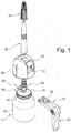
- FIG 1 a product dispenser 11 is shown in an exploded view.
- a pressure vessel 12 adopts a vessel opening 14, which is opened by a valve 16 ( Figure 3 ) is closed, an adapter 18 on.
- This adapter 18 comprises an adapter base body 19 which can be placed on the container opening 14 and an actuating lever 21 with a handle 22 which is connected to the adapter base body 19 by a pivot arrangement 23.
- the adapter base body 19 has an output sleeve 25, onto which a grommet 26 can be fastened, in particular screwed on. This allows the grommet 26 to be replaced.
- a closure 27 is provided at one end of the spout 26 in order to prevent the medium in the spout 26 from drying out.
- a cap 29 is provided which essentially surrounds the adapter 18.
- This cap 29 has a recess 31, through which the actuating lever 21 is led out so that the handle 22 is positioned outside the cap 29.
- Figure 2 are the in Figure 1 shown components in an assembled position.
- the Figure 2 shows a product dispenser 11 ready for sale.
- a region of the recess 31 in the cap 29 is closed by a tamper-evident closure 32.
- This tamper-evident closure 32 is positioned in the recess 31 by several web-shaped connections 33.
- the tamper-evident closure 32 can be released at at least two web-shaped connections 32 to the recess 31, so that the quality closure remains loose and / or pivotable in the recess 31.
- the web-shaped connections 33 form a predetermined breaking point.
- the recess 30 can facilitate the release of the tamper-evident closure 32 in that a tool can be inserted. If the tamper-evident closure 32 is missing, the user can clearly see that the product dispenser 11 has already been opened or used.
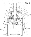
- FIG. 11 is a schematic sectional view of the product dispenser 11 in FIG Figure 2 shown.
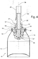
- the Figure 4 shows a further sectional view rotated by 90 ° Figure 3 .
- a valve 16, which closes the container opening 14, is attached to a container opening 14 of the pressure container 12.
- the valve 16 has a valve body 36 which comprises an outer circumferential edge so that this outer circumferential edge engages the container opening 14. For example, this can be done by screwing or flanging.
- the valve 16 comprises a valve closing member 37 which is movable along a longitudinal axis 38 of the valve 16 or the longitudinal axis 38 of the adapter base body 19. To open the valve closing member 37, it is moved in the direction of the pressure vessel 12 against a restoring element 39, in particular a spring, in order to open a valve opening 41.
- a medium stored in the pressure vessel 12 passes through this valve opening 41 for dispensing.
- This valve 16 can correspond to the embodiment which, for example, in FIG DE 10 2008 051 888 A1 is described, to which reference is made in full.
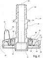
- the adapter 18 can be placed on the container opening 14. This adapter 18 is in Figure 5 perspective and in Figure 6 shown in a sectional view. The adapter 18 according to Figures 5 and 6th is shown in a starting position 68.
- a flange 44 which is preferably aligned coaxially to the longitudinal axis 38, is provided on the adapter base body 19.
- An end face 45 extends between the flange 44 and the dispensing sleeve 25.
- a fastening section 48 Adjacent to the end face 45 and the flange 44, a fastening section 48 is provided which extends at least in sections along the flange 44.
- the fastening section 46 comprises webs 48 which are provided at a distance from the flange 44 and form a receiving area in between.
- a locking lug 54 is provided on the lower edge of the flange 44 on the lower edge of the flange 44 on the lower edge of the flange 44.
- a fastening section 46 can be formed which, in a latching manner, can grip around the flange or an edge 47 of the container opening 14 or of the pressure container 12.
- a latching, clamping or snap connection can preferably be provided.
- a latching element 42 is also provided on an outer circumference, which forms a detachable latching connection with a latching element 43 on an inner side of the cap 29. As a result, the cap 29 can be clipped onto the adapter.
- the adapter base body 19 furthermore comprises the dispensing sleeve 25, which is connected to the adapter base body 19 by an elastic connection 49.
- the end face 45 extends between the adapter base body 19 and the dispensing sleeve 25. This end face 45, viewed in a sectional view, is oriented like a roof. The end face 45 covers the fastening section or adjoins it.
- the elastic connection 49 extends between the dispensing sleeve 25 and the end face 45 elastic connection 49 and the end face 45 in a common plane.
- the elastic connection 49 is formed by an elastic membrane which, according to the embodiment shown, extends over the entire surface between the end face 45 of the flange 44 and the dispensing sleeve 25.
- the dispensing sleeve 25 can be changed in its position along the longitudinal axis 38 with respect to the adapter base body 19.
- the dispensing sleeve 25 is made in particular from the in Figure 5
- the starting position 68 shown can be displaced relative to the adapter base body 19 in the direction of the valve 16 of the pressure vessel 12.
- One such active position 69 is in the Figures 7 and 8th shown.
- the Figure 6 further shows that a connector 51 is provided at one end of the dispensing sleeve 25.
- This connection 51 preferably encompasses the valve closing member 37.
- a receptacle 52 is provided on the dispensing sleeve 25, onto which the spout 26 can be placed or screwed.
- the dispensing sleeve 25 has a through hole 53 which extends from the connection 51 to the receptacle 52.
- laterally protruding cams 57 are provided on the dispensing sleeve 25.
- two radially protruding and opposing cams 57 are formed.
- At least one actuating element 56 on the actuating lever 21 can act on these cams 57 of the dispensing sleeve 25 in order to actuate the dispensing sleeve 25.
- This operating lever 56 is for example in Figure 1 and is shown below in Figure 5 described.
- the receptacle 52 on the dispensing sleeve 25 is delimited by an annular collar 58 so that the spout 26 assumes a defined position after it has been placed on.
- a projection 59 is provided from this annular collar 58 in the direction of the elastic connection 49, which protrudes in the form of a web with respect to the outer circumference of the dispensing sleeve 25 and is arranged at a distance from the elastic connection 49.
- This head start 59 forms part of a transport lock for the actuating lever 21 and handle 22, as will be shown below in FIG Figure 9 will be discussed.
- the adapter 18 is with respect to its in the Figures 5 and 6th Components shown are preferably formed in one piece.
- the adapter base body 19 also receives at least one, preferably two, pivot bolts 61, which serve to form the pivot arrangement 23 together with the actuating lever 21.
- the pivot pins 61 form a common pivot axis 62.
- the pivot pins 61 are aligned in mirror image to one another and allow the actuating lever 21 to be easily attached and mounted so that the recesses in the form of an elongated hole 63 can be placed on the pivot pin 61 at a free end.
- the adapter 18 is produced as an injection-molded part made of plastic.
- individual components can also be put together by means of a latching, snap-in or clamping connection in order to form the adapter 18.
- FIG. 7 A perspective view of the adapter 18 in an active position 69 is shown.
- FIG. 11 shows a sectional view of the adapter 18 according to FIG Figure 7 .
- the transfer of the adapter 18 into the active position 69 is made possible by the elastic connection 49.
- the elastic connection 49 By an actuating force along the longitudinal axis 38, the dispensing sleeve 25 and thus the connection 51 can be moved downward, that is, in the direction of the pressure vessel 12.
- the elastic connection 49 can deform.
- An adjusting movement can be achieved by bending an elastic connection 49.
- the elastic connection 49 is advantageously evenly loaded, so that an annular recess is formed by the elastic connection 49.
- a plurality of webs extending radially outward with gaps formed between them can also be provided.
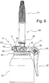
- FIG. 9 the actuating lever 21 with the handle 22 is shown in the locking position 66.
- the pivot arrangement 23 is provided in a first end position 71.
- the actuating lever 21 is moved into this first end position 61 by a sliding movement at right angles to the longitudinal axis 38 of the pressure vessel 12.
- the handle 22 is positioned close to the outer wall of the pressure vessel 12 or rests against it.
- the projection 59 on the outside of the dispensing sleeve 25 engages on an outside of the actuating lever 21, whereby a pivoting movement of the actuating lever 21 in the direction of the spout 26 is blocked.
- the pivoting movement of the actuating lever 21 is blocked by a stop 76 which rests on the adapter base body 19.
- the elongated hole (s) 63 can have a constriction so that when the pivot axis 62 is moved into the first end position 71, a locking resistance has to be overcome, through which the actuating lever 21 can subsequently be held in this first end position 71 .
- the actuating element 56 of the actuating lever is positioned adjacent to the cam 57 and is thus out of engagement.
- the elongated holes 63 formed on the actuating lever 21 have an angled contour. As a result, the actuating lever 21 with the handle 22 is held close to the pressure vessel 12 when it is arranged in the first end position 71. In an unlocked position 67 of the actuating lever 21 and handle 22, these can be further removed from the adapter body 19 both in the direction of the longitudinal axis 38 and laterally to the longitudinal axis 38 in order to enable the handle 22 to be safely operated to dispense the medium.
- the unlocking position 67 of the operating lever 21 is shown in FIG Figure 8 shown.
- the pivot axis 62 is located within the elongated hole 63 in a second end position 73. In this end position, the actuating element 56 rests on the cam 57.
- the actuating lever 21 and the handle 22 are arranged in an initial position 68. In this starting position, the product dispenser 11 is ready to dispense the medium when the handle 22 is actuated.
- the operating lever 21 automatically returns with the handle 22 from the active position 69 to the starting position 68. This independent transfer into a closed position is generated by the return element 39 of the valve 16.
- the actuating lever 21 is arranged in the second end position 73 of the pivot arrangement 23.
- the actuating element 56 is positioned relative to the projection 59 in such a way that the dispensing sleeve 25 can be moved towards the pressure vessel 12 along the longitudinal axis 38 during the pivoting movement of the handle 22.
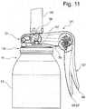
- FIG 12 a schematic sectional view of the product dispenser with an unlocked adapter 18 is shown.
- the handle 22 is moved into an active position 69 for dispensing the medium.
- This sectional view shows that the dispensing sleeve 25 moves with respect to the annular adapter base body 19 along the longitudinal axis 38 is. This can be seen from a bend 50 of the elastic connection 49, which extends between the dispensing sleeve 25 and the annular adapter base body 19.
- the adapter 18 can be provided as a sales unit.
- the operating lever 21 is mounted on the pivot axis 62 and forms a fixed pivot arrangement.
- the cap 29 can also be attached to the adapter base body 19. To attach the cap 29, the handle 22 and the actuating lever 21 are passed through the recess 31 of the cap 29 and then the cap 29 is connected to the adapter base body 19, in particular locked.
- This structural unit can then be connected to the container opening 14 of the pressure container 12 by a clip or latch connection with the circumferential edge.
- the spout 26 can optionally be screwed on in order to complete the product dispenser 11.
Landscapes
- Engineering & Computer Science (AREA)
- Mechanical Engineering (AREA)
- Chemical & Material Sciences (AREA)
- Dispersion Chemistry (AREA)
- Containers And Packaging Bodies Having A Special Means To Remove Contents (AREA)
- Devices For Dispensing Beverages (AREA)
- Closures For Containers (AREA)
Claims (12)
- Adaptateur pour un distributeur de produit (11), pourvu d'un corps de base d'adaptateur (19) destiné à positionner l'adaptateur (18) sur une ouverture de récipient (14) d'un récipient sous pression (12), d'une douille de distribution (25) qui peut être déplacée par rapport au corps de base d'adaptateur (19) le long d'un axe longitudinal (38) du corps de base d'adaptateur (19) et ladite douille de distribution (25) étant disposée de manière déplaçable par rapport au corps de base d'adaptateur (19) grâce à une liaison élastique (49) qui est prévue, en tant que membrane en forme d'anneau ou de disque, entre le corps de base d'adaptateur (19) et la douille de distribution (25), caractérisé en ce qu'un mouvement de déplacement guidé d'une soupape (16) du distributeur de produit (11) est réalisé grâce à la liaison élastique (49).
- Adaptateur selon la revendication 1, caractérisé en ce que la douille de distribution (25) est disposée de manière automaintenue dans une position initiale (68) par rapport au corps de base d'adaptateur (19) et que ladite douille de distribution (25) peut passer dans une position active (69) grâce à une force exercée au moins en partie le long de l'axe longitudinal (38) du corps de base d'adaptateur (19) .
- Adaptateur selon la revendication 2, caractérisé en ce que la liaison élastique (49) fait passer la douille de distribution (25) de manière autonome dans la position initiale (68) par rapport au corps de base d'adaptateur (19) au moyen d'une force de rappel qui peut être générée lorsque la douille de distribution (25) passe de la position initiale (68) à la position active (69).
- Adaptateur selon l'une quelconque des revendications précédentes, caractérisé en ce que le corps de base d'adaptateur (19) présente une bride (44) orientée de manière coaxiale par rapport à l'axe longitudinal (38) et en ce qu'une face frontale (45) s'étend entre ladite bride (44) et la douille de distribution (25) et est inclinée par rapport audit axe longitudinal (38) et en ce que la liaison élastique (49) est prévue entre la douille de distribution (25) et la face frontale (45).
- Adaptateur selon la revendication 4, caractérisé en ce que lorsque la douille de distribution (25) se trouve dans la position initiale (68) par rapport au corps de base d'adaptateur (19), la face frontale (45) et la liaison élastique (49) sont disposées dans un plan commun.
- Adaptateur selon l'une quelconque des revendications précédentes, caractérisé en ce qu'à l'intérieur de la bride (44) est prévue une partie de fixation (46) qui s'étend au moins en partie le long de la bride (44) et qui peut être fixée à un rebord (47) du récipient sous pression (12) grâce à un assemblage à enclenchement et/ou à déclic.
- Adaptateur selon la revendication 6, caractérisé en ce que la partie de fixation (46) prévue sur la bride (44) présente plusieurs montants (48) espacés les uns des autres qui forment avec la bride (44) une zone de réception en forme de U grâce à laquelle la partie de fixation s'assemble par conjugaison de forme au rebord (47) du récipient sous pression (12) .
- Adaptateur selon l'une quelconque des revendications précédentes, caractérisé en ce que sur la douille de distribution (25) est prévu, dans la direction de mise en place du corps de base d'adaptateur (19) sur le récipient sous pression (12), un raccord (51) permettant le positionnement par rapport à la soupape (16) du récipient sous pression (12).
- Adaptateur selon l'une quelconque des revendications précédentes, caractérisé en ce que la douille de distribution (25) du corps de base d'adaptateur (19) présente, à une extrémité libre, une réception (52) permettant de recevoir un bec (26) .
- Adaptateur selon l'une quelconque des revendications précédentes, caractérisé en ce que le corps de base d'adaptateur (19), la douille de distribution (25) et au moins la liaison élastique (49) sont réalisés en une seule pièce.
- Adaptateur selon l'une quelconque des revendications précédentes, caractérisé en ce que le corps de base d'adaptateur (19), la douille de distribution (25) et au moins la liaison élastique (49) sont réalisés en tant que pièce en plastique moulée par injection.
- Adaptateur selon l'une quelconque des revendications précédentes, caractérisé en ce que le corps de base d'adaptateur (19), la douille de distribution (25) et au moins la liaison élastique (49) sont réalisés en un élastomère thermoplastique, en particulier en polypropylène ou en polyéthylène.
Applications Claiming Priority (1)
| Application Number | Priority Date | Filing Date | Title |
|---|---|---|---|
| DE102018108845.0A DE102018108845A1 (de) | 2018-04-13 | 2018-04-13 | Adapter für Produktspender und Produktspender |
Publications (2)
| Publication Number | Publication Date |
|---|---|
| EP3552988A1 EP3552988A1 (fr) | 2019-10-16 |
| EP3552988B1 true EP3552988B1 (fr) | 2021-06-09 |
Family
ID=66102873
Family Applications (1)
| Application Number | Title | Priority Date | Filing Date |
|---|---|---|---|
| EP19167850.7A Active EP3552988B1 (fr) | 2018-04-13 | 2019-04-08 | Adaptateur pour le distributeur de produit et distributeur de produit |
Country Status (3)
| Country | Link |
|---|---|
| US (1) | US20190315561A1 (fr) |
| EP (1) | EP3552988B1 (fr) |
| DE (1) | DE102018108845A1 (fr) |
Families Citing this family (1)
| Publication number | Priority date | Publication date | Assignee | Title |
|---|---|---|---|---|
| GB2597471A (en) * | 2020-07-22 | 2022-02-02 | Innovolo Ltd | Aerosol canister cap |
Family Cites Families (17)
| Publication number | Priority date | Publication date | Assignee | Title |
|---|---|---|---|---|
| US2169779A (en) * | 1937-04-08 | 1939-08-15 | Food Dispenser Company | Closure for dispensers |
| JPH0794268B2 (ja) * | 1985-10-16 | 1995-10-11 | ロセプ−ル−ソル ホ−ルデイングス リミテツド | エアロゾル用弁作動装置 |
| JP4160256B2 (ja) * | 1997-10-07 | 2008-10-01 | ロセップ ルーソル ホールディングス リミテッド | ディスペンシング装置 |
| GB9930773D0 (en) * | 1999-12-30 | 2000-02-16 | Rocep Lusol Holdings | Dispensing apparatus |
| US6340103B1 (en) * | 2000-07-18 | 2002-01-22 | Advanced Packaging Corp. | Dispensing mechanism for pressurized container |
| JP2004188074A (ja) * | 2002-12-13 | 2004-07-08 | Mitani Valve Co Ltd | 鼻腔用スパウト |
| FR2860768B1 (fr) * | 2003-10-09 | 2006-08-04 | Airlessystems | Tete de distribution de produit fluide |
| FR2865463B1 (fr) * | 2004-01-27 | 2006-02-24 | Oreal | Tete de distribution verrouillable |
| US7249692B2 (en) * | 2004-11-29 | 2007-07-31 | Seaquistperfect Dispensing Foreign, Inc. | Dispenser with lock |
| ATE542756T1 (de) * | 2006-03-03 | 2012-02-15 | Clayton Corp | Aerosoldosenventil und abdeckungsanordnung |
| DE102007049334A1 (de) * | 2007-10-12 | 2009-04-16 | Henkel Ag & Co. Kgaa | Druckverpackung für viskose Materialien |
| FR2923811B1 (fr) * | 2007-11-15 | 2009-12-04 | Oreal | Recipient equipe d'un dispositif de securite. |
| DE102008051888B4 (de) | 2008-10-16 | 2011-02-03 | C. Ehrensperger Ag | Ventil für einen Behälter zur Abgabe von unter Druck stehendem Fluid |
| US8235253B2 (en) * | 2008-12-12 | 2012-08-07 | Alemite Llc | Easy shift dual-mode pistol-grip grease gun |
| DE102009044280A1 (de) | 2009-10-16 | 2011-05-05 | Lindal Dispenser Gmbh | Produktspender |
| US10435227B2 (en) * | 2012-04-24 | 2019-10-08 | Aptargroup, Inc | Trigger operated aerosol dispenser |
| US9315314B2 (en) * | 2014-06-27 | 2016-04-19 | Westrock Dispensing Systems, Inc. | Dual actuated aerosol devices |
-
2018
- 2018-04-13 DE DE102018108845.0A patent/DE102018108845A1/de not_active Withdrawn
-
2019
- 2019-04-08 US US16/377,286 patent/US20190315561A1/en not_active Abandoned
- 2019-04-08 EP EP19167850.7A patent/EP3552988B1/fr active Active
Non-Patent Citations (1)
| Title |
|---|
| None * |
Also Published As
| Publication number | Publication date |
|---|---|
| EP3552988A1 (fr) | 2019-10-16 |
| DE102018108845A1 (de) | 2019-10-17 |
| US20190315561A1 (en) | 2019-10-17 |
Similar Documents
| Publication | Publication Date | Title |
|---|---|---|
| EP2804504B1 (fr) | Distributeur de fluides | |
| DE60133073T2 (de) | Abgabeeinheit für die gleichzeitige Abgabe von zwei Produkten | |
| DE69607260T2 (de) | Befestigungsring mit Doppelindexiervorrichtung | |
| DE4341229C2 (de) | Pipettensystem | |
| DE69700430T2 (de) | Flüssigkeitsausgabevorrichtung mit doppelter sichercheit | |
| EP0653359B1 (fr) | Dispositif de fermeture d'un récipient équipé d'une pompe à main | |
| EP3094414B1 (fr) | Dispositif de distribution | |
| EP3765205B1 (fr) | Tête de distribution et distributeur | |
| EP3552989B1 (fr) | Adaptateur pour le distributeur de produit et distributeur de produit | |
| DE102018003741B4 (de) | Abgabevorrichtung mit reibverschweißtem Ventilteller | |
| EP1015804A1 (fr) | Dispositif de raccordement pour une partie de tube ou de tuyau | |
| EP1313652A2 (fr) | Bombe a aerosol | |
| EP3984652A1 (fr) | Distributeur de liquide | |
| DE102009018528A1 (de) | Spender zur Ausgabe eines Materials aus einem Behälter | |
| DE69910891T2 (de) | Ventil sowie Aufbewahrungs- und Ausgabevorrichtung mit einem solchen Ventil | |
| EP4039235A1 (fr) | Distributeur de liquide sécurisé | |
| EP4008442B1 (fr) | Agencement de distribution et distributeur | |
| EP3552988B1 (fr) | Adaptateur pour le distributeur de produit et distributeur de produit | |
| WO1991017930A2 (fr) | Emballage a plusieurs constituants | |
| DE102020120228A1 (de) | Fließbecher für eine Spritzpistole mit einer Belüftungseinrichtung | |
| DE3232340C1 (de) | Selbstschliessender Kraftstoffbehaelterverschluss | |
| DE19532774C1 (de) | Betankungsanordnung zum roboterfähigen Betanken von Fahrzeugen | |
| DE2425004C2 (de) | Kupplungsvorrichtung zum Verbinden eines Schlauchs mit einem verdichtetes oder verflüssigtes Gas enthaltenden Behälter | |
| DE19532775C1 (de) | Betankungsanordnung zum roboterfähigen Betanken mit Kraftstoff | |
| EP1481734B1 (fr) | Fermeture par une tête de pulvérisation |
Legal Events
| Date | Code | Title | Description |
|---|---|---|---|
| PUAI | Public reference made under article 153(3) epc to a published international application that has entered the european phase |
Free format text: ORIGINAL CODE: 0009012 |
|
| STAA | Information on the status of an ep patent application or granted ep patent |
Free format text: STATUS: THE APPLICATION HAS BEEN PUBLISHED |
|
| AK | Designated contracting states |
Kind code of ref document: A1 Designated state(s): AL AT BE BG CH CY CZ DE DK EE ES FI FR GB GR HR HU IE IS IT LI LT LU LV MC MK MT NL NO PL PT RO RS SE SI SK SM TR |
|
| AX | Request for extension of the european patent |
Extension state: BA ME |
|
| STAA | Information on the status of an ep patent application or granted ep patent |
Free format text: STATUS: REQUEST FOR EXAMINATION WAS MADE |
|
| 17P | Request for examination filed |
Effective date: 20200416 |
|
| RBV | Designated contracting states (corrected) |
Designated state(s): AL AT BE BG CH CY CZ DE DK EE ES FI FR GB GR HR HU IE IS IT LI LT LU LV MC MK MT NL NO PL PT RO RS SE SI SK SM TR |
|
| RIC1 | Information provided on ipc code assigned before grant |
Ipc: B65D 83/16 20060101AFI20200903BHEP |
|
| GRAP | Despatch of communication of intention to grant a patent |
Free format text: ORIGINAL CODE: EPIDOSNIGR1 |
|
| STAA | Information on the status of an ep patent application or granted ep patent |
Free format text: STATUS: GRANT OF PATENT IS INTENDED |
|
| INTG | Intention to grant announced |
Effective date: 20201112 |
|
| GRAS | Grant fee paid |
Free format text: ORIGINAL CODE: EPIDOSNIGR3 |
|
| GRAA | (expected) grant |
Free format text: ORIGINAL CODE: 0009210 |
|
| STAA | Information on the status of an ep patent application or granted ep patent |
Free format text: STATUS: THE PATENT HAS BEEN GRANTED |
|
| AK | Designated contracting states |
Kind code of ref document: B1 Designated state(s): AL AT BE BG CH CY CZ DE DK EE ES FI FR GB GR HR HU IE IS IT LI LT LU LV MC MK MT NL NO PL PT RO RS SE SI SK SM TR |
|
| REG | Reference to a national code |
Ref country code: GB Ref legal event code: FG4D Free format text: NOT ENGLISH |
|
| REG | Reference to a national code |
Ref country code: CH Ref legal event code: EP Ref country code: AT Ref legal event code: REF Ref document number: 1400320 Country of ref document: AT Kind code of ref document: T Effective date: 20210615 |
|
| REG | Reference to a national code |
Ref country code: DE Ref legal event code: R096 Ref document number: 502019001564 Country of ref document: DE |
|
| REG | Reference to a national code |
Ref country code: IE Ref legal event code: FG4D Free format text: LANGUAGE OF EP DOCUMENT: GERMAN |
|
| REG | Reference to a national code |
Ref country code: NL Ref legal event code: FP |
|
| REG | Reference to a national code |
Ref country code: LT Ref legal event code: MG9D |
|
| PG25 | Lapsed in a contracting state [announced via postgrant information from national office to epo] |
Ref country code: BG Free format text: LAPSE BECAUSE OF FAILURE TO SUBMIT A TRANSLATION OF THE DESCRIPTION OR TO PAY THE FEE WITHIN THE PRESCRIBED TIME-LIMIT Effective date: 20210909 Ref country code: HR Free format text: LAPSE BECAUSE OF FAILURE TO SUBMIT A TRANSLATION OF THE DESCRIPTION OR TO PAY THE FEE WITHIN THE PRESCRIBED TIME-LIMIT Effective date: 20210609 Ref country code: LT Free format text: LAPSE BECAUSE OF FAILURE TO SUBMIT A TRANSLATION OF THE DESCRIPTION OR TO PAY THE FEE WITHIN THE PRESCRIBED TIME-LIMIT Effective date: 20210609 Ref country code: FI Free format text: LAPSE BECAUSE OF FAILURE TO SUBMIT A TRANSLATION OF THE DESCRIPTION OR TO PAY THE FEE WITHIN THE PRESCRIBED TIME-LIMIT Effective date: 20210609 |
|
| PG25 | Lapsed in a contracting state [announced via postgrant information from national office to epo] |
Ref country code: GR Free format text: LAPSE BECAUSE OF FAILURE TO SUBMIT A TRANSLATION OF THE DESCRIPTION OR TO PAY THE FEE WITHIN THE PRESCRIBED TIME-LIMIT Effective date: 20210910 Ref country code: LV Free format text: LAPSE BECAUSE OF FAILURE TO SUBMIT A TRANSLATION OF THE DESCRIPTION OR TO PAY THE FEE WITHIN THE PRESCRIBED TIME-LIMIT Effective date: 20210609 Ref country code: NO Free format text: LAPSE BECAUSE OF FAILURE TO SUBMIT A TRANSLATION OF THE DESCRIPTION OR TO PAY THE FEE WITHIN THE PRESCRIBED TIME-LIMIT Effective date: 20210909 Ref country code: SE Free format text: LAPSE BECAUSE OF FAILURE TO SUBMIT A TRANSLATION OF THE DESCRIPTION OR TO PAY THE FEE WITHIN THE PRESCRIBED TIME-LIMIT Effective date: 20210609 Ref country code: RS Free format text: LAPSE BECAUSE OF FAILURE TO SUBMIT A TRANSLATION OF THE DESCRIPTION OR TO PAY THE FEE WITHIN THE PRESCRIBED TIME-LIMIT Effective date: 20210609 |
|
| PG25 | Lapsed in a contracting state [announced via postgrant information from national office to epo] |
Ref country code: SK Free format text: LAPSE BECAUSE OF FAILURE TO SUBMIT A TRANSLATION OF THE DESCRIPTION OR TO PAY THE FEE WITHIN THE PRESCRIBED TIME-LIMIT Effective date: 20210609 Ref country code: ES Free format text: LAPSE BECAUSE OF FAILURE TO SUBMIT A TRANSLATION OF THE DESCRIPTION OR TO PAY THE FEE WITHIN THE PRESCRIBED TIME-LIMIT Effective date: 20210609 Ref country code: EE Free format text: LAPSE BECAUSE OF FAILURE TO SUBMIT A TRANSLATION OF THE DESCRIPTION OR TO PAY THE FEE WITHIN THE PRESCRIBED TIME-LIMIT Effective date: 20210609 Ref country code: SM Free format text: LAPSE BECAUSE OF FAILURE TO SUBMIT A TRANSLATION OF THE DESCRIPTION OR TO PAY THE FEE WITHIN THE PRESCRIBED TIME-LIMIT Effective date: 20210609 Ref country code: RO Free format text: LAPSE BECAUSE OF FAILURE TO SUBMIT A TRANSLATION OF THE DESCRIPTION OR TO PAY THE FEE WITHIN THE PRESCRIBED TIME-LIMIT Effective date: 20210609 Ref country code: PT Free format text: LAPSE BECAUSE OF FAILURE TO SUBMIT A TRANSLATION OF THE DESCRIPTION OR TO PAY THE FEE WITHIN THE PRESCRIBED TIME-LIMIT Effective date: 20211011 Ref country code: CZ Free format text: LAPSE BECAUSE OF FAILURE TO SUBMIT A TRANSLATION OF THE DESCRIPTION OR TO PAY THE FEE WITHIN THE PRESCRIBED TIME-LIMIT Effective date: 20210609 |
|
| PG25 | Lapsed in a contracting state [announced via postgrant information from national office to epo] |
Ref country code: PL Free format text: LAPSE BECAUSE OF FAILURE TO SUBMIT A TRANSLATION OF THE DESCRIPTION OR TO PAY THE FEE WITHIN THE PRESCRIBED TIME-LIMIT Effective date: 20210609 |
|
| REG | Reference to a national code |
Ref country code: DE Ref legal event code: R097 Ref document number: 502019001564 Country of ref document: DE |
|
| PLBE | No opposition filed within time limit |
Free format text: ORIGINAL CODE: 0009261 |
|
| STAA | Information on the status of an ep patent application or granted ep patent |
Free format text: STATUS: NO OPPOSITION FILED WITHIN TIME LIMIT |
|
| PG25 | Lapsed in a contracting state [announced via postgrant information from national office to epo] |
Ref country code: DK Free format text: LAPSE BECAUSE OF FAILURE TO SUBMIT A TRANSLATION OF THE DESCRIPTION OR TO PAY THE FEE WITHIN THE PRESCRIBED TIME-LIMIT Effective date: 20210609 |
|
| 26N | No opposition filed |
Effective date: 20220310 |
|
| PG25 | Lapsed in a contracting state [announced via postgrant information from national office to epo] |
Ref country code: AL Free format text: LAPSE BECAUSE OF FAILURE TO SUBMIT A TRANSLATION OF THE DESCRIPTION OR TO PAY THE FEE WITHIN THE PRESCRIBED TIME-LIMIT Effective date: 20210609 |
|
| PG25 | Lapsed in a contracting state [announced via postgrant information from national office to epo] |
Ref country code: IT Free format text: LAPSE BECAUSE OF FAILURE TO SUBMIT A TRANSLATION OF THE DESCRIPTION OR TO PAY THE FEE WITHIN THE PRESCRIBED TIME-LIMIT Effective date: 20210609 |
|
| PG25 | Lapsed in a contracting state [announced via postgrant information from national office to epo] |
Ref country code: MC Free format text: LAPSE BECAUSE OF FAILURE TO SUBMIT A TRANSLATION OF THE DESCRIPTION OR TO PAY THE FEE WITHIN THE PRESCRIBED TIME-LIMIT Effective date: 20210609 Ref country code: LU Free format text: LAPSE BECAUSE OF NON-PAYMENT OF DUE FEES Effective date: 20220408 |
|
| PG25 | Lapsed in a contracting state [announced via postgrant information from national office to epo] |
Ref country code: IE Free format text: LAPSE BECAUSE OF NON-PAYMENT OF DUE FEES Effective date: 20220408 |
|
| P01 | Opt-out of the competence of the unified patent court (upc) registered |
Effective date: 20230515 |
|
| PG25 | Lapsed in a contracting state [announced via postgrant information from national office to epo] |
Ref country code: HU Free format text: LAPSE BECAUSE OF FAILURE TO SUBMIT A TRANSLATION OF THE DESCRIPTION OR TO PAY THE FEE WITHIN THE PRESCRIBED TIME-LIMIT; INVALID AB INITIO Effective date: 20190408 |
|
| PG25 | Lapsed in a contracting state [announced via postgrant information from national office to epo] |
Ref country code: MK Free format text: LAPSE BECAUSE OF FAILURE TO SUBMIT A TRANSLATION OF THE DESCRIPTION OR TO PAY THE FEE WITHIN THE PRESCRIBED TIME-LIMIT Effective date: 20210609 Ref country code: CY Free format text: LAPSE BECAUSE OF FAILURE TO SUBMIT A TRANSLATION OF THE DESCRIPTION OR TO PAY THE FEE WITHIN THE PRESCRIBED TIME-LIMIT Effective date: 20210609 |
|
| PG25 | Lapsed in a contracting state [announced via postgrant information from national office to epo] |
Ref country code: TR Free format text: LAPSE BECAUSE OF FAILURE TO SUBMIT A TRANSLATION OF THE DESCRIPTION OR TO PAY THE FEE WITHIN THE PRESCRIBED TIME-LIMIT Effective date: 20210609 |
|
| PG25 | Lapsed in a contracting state [announced via postgrant information from national office to epo] |
Ref country code: MT Free format text: LAPSE BECAUSE OF FAILURE TO SUBMIT A TRANSLATION OF THE DESCRIPTION OR TO PAY THE FEE WITHIN THE PRESCRIBED TIME-LIMIT Effective date: 20210609 |
|
| REG | Reference to a national code |
Ref country code: AT Ref legal event code: MM01 Ref document number: 1400320 Country of ref document: AT Kind code of ref document: T Effective date: 20240408 |
|
| PGFP | Annual fee paid to national office [announced via postgrant information from national office to epo] |
Ref country code: DE Payment date: 20250410 Year of fee payment: 7 |
|
| PGFP | Annual fee paid to national office [announced via postgrant information from national office to epo] |
Ref country code: CH Payment date: 20250501 Year of fee payment: 7 |
|
| PG25 | Lapsed in a contracting state [announced via postgrant information from national office to epo] |
Ref country code: AT Free format text: LAPSE BECAUSE OF NON-PAYMENT OF DUE FEES Effective date: 20240408 |
|
| PGFP | Annual fee paid to national office [announced via postgrant information from national office to epo] |
Ref country code: NL Payment date: 20260227 Year of fee payment: 8 |
|
| PGFP | Annual fee paid to national office [announced via postgrant information from national office to epo] |
Ref country code: GB Payment date: 20260216 Year of fee payment: 8 |
|
| PGFP | Annual fee paid to national office [announced via postgrant information from national office to epo] |
Ref country code: AT Payment date: 20260410 Year of fee payment: 5 |
|
| PGFP | Annual fee paid to national office [announced via postgrant information from national office to epo] |
Ref country code: BE Payment date: 20260317 Year of fee payment: 8 |
|
| PGFP | Annual fee paid to national office [announced via postgrant information from national office to epo] |
Ref country code: FR Payment date: 20260223 Year of fee payment: 8 |