EP3553007B1 - Dispositif d'épissage de fil synthétique - Google Patents
Dispositif d'épissage de fil synthétique Download PDFInfo
- Publication number
- EP3553007B1 EP3553007B1 EP19167520.6A EP19167520A EP3553007B1 EP 3553007 B1 EP3553007 B1 EP 3553007B1 EP 19167520 A EP19167520 A EP 19167520A EP 3553007 B1 EP3553007 B1 EP 3553007B1
- Authority
- EP
- European Patent Office
- Prior art keywords
- yarn
- clamping
- passage
- clamping member
- line
- Prior art date
- Legal status (The legal status is an assumption and is not a legal conclusion. Google has not performed a legal analysis and makes no representation as to the accuracy of the status listed.)
- Active
Links
Images





Classifications
-
- B—PERFORMING OPERATIONS; TRANSPORTING
- B65—CONVEYING; PACKING; STORING; HANDLING THIN OR FILAMENTARY MATERIAL
- B65H—HANDLING THIN OR FILAMENTARY MATERIAL, e.g. SHEETS, WEBS, CABLES
- B65H69/00—Methods of, or devices for, interconnecting successive lengths of material; Knot-tying devices ;Control of the correct working of the interconnecting device
- B65H69/06—Methods of, or devices for, interconnecting successive lengths of material; Knot-tying devices ;Control of the correct working of the interconnecting device by splicing
- B65H69/061—Methods of, or devices for, interconnecting successive lengths of material; Knot-tying devices ;Control of the correct working of the interconnecting device by splicing using pneumatic means
-
- B—PERFORMING OPERATIONS; TRANSPORTING
- B65—CONVEYING; PACKING; STORING; HANDLING THIN OR FILAMENTARY MATERIAL
- B65H—HANDLING THIN OR FILAMENTARY MATERIAL, e.g. SHEETS, WEBS, CABLES
- B65H67/00—Replacing or removing cores, receptacles, or completed packages at paying-out, winding, or depositing stations
- B65H67/08—Automatic end-finding and material-interconnecting arrangements
- B65H67/081—Automatic end-finding and material-interconnecting arrangements acting after interruption of the winding process, e.g. yarn breakage, yarn cut or package replacement
-
- B—PERFORMING OPERATIONS; TRANSPORTING
- B65—CONVEYING; PACKING; STORING; HANDLING THIN OR FILAMENTARY MATERIAL
- B65H—HANDLING THIN OR FILAMENTARY MATERIAL, e.g. SHEETS, WEBS, CABLES
- B65H69/00—Methods of, or devices for, interconnecting successive lengths of material; Knot-tying devices ;Control of the correct working of the interconnecting device
- B65H69/06—Methods of, or devices for, interconnecting successive lengths of material; Knot-tying devices ;Control of the correct working of the interconnecting device by splicing
- B65H69/061—Methods of, or devices for, interconnecting successive lengths of material; Knot-tying devices ;Control of the correct working of the interconnecting device by splicing using pneumatic means
- B65H69/063—Preparation of the yarn ends
-
- B—PERFORMING OPERATIONS; TRANSPORTING
- B65—CONVEYING; PACKING; STORING; HANDLING THIN OR FILAMENTARY MATERIAL
- B65H—HANDLING THIN OR FILAMENTARY MATERIAL, e.g. SHEETS, WEBS, CABLES
- B65H2402/00—Constructional details of the handling apparatus
- B65H2402/40—Details of frames, housings or mountings of the whole handling apparatus
- B65H2402/41—Portable or hand-held apparatus
- B65H2402/414—Manual tools for filamentary material, e.g. for mounting or removing a bobbin, measuring tension or splicing
-
- B—PERFORMING OPERATIONS; TRANSPORTING
- B65—CONVEYING; PACKING; STORING; HANDLING THIN OR FILAMENTARY MATERIAL
- B65H—HANDLING THIN OR FILAMENTARY MATERIAL, e.g. SHEETS, WEBS, CABLES
- B65H2701/00—Handled material; Storage means
- B65H2701/30—Handled filamentary material
- B65H2701/31—Textiles threads or artificial strands of filaments
-
- B—PERFORMING OPERATIONS; TRANSPORTING
- B65—CONVEYING; PACKING; STORING; HANDLING THIN OR FILAMENTARY MATERIAL
- B65H—HANDLING THIN OR FILAMENTARY MATERIAL, e.g. SHEETS, WEBS, CABLES
- B65H2701/00—Handled material; Storage means
- B65H2701/30—Handled filamentary material
- B65H2701/31—Textiles threads or artificial strands of filaments
- B65H2701/313—Synthetic polymer threads
Definitions
- the invention relates to a synthetic yarn splicer.
- Patent Literature 1 JP H10-17214 A
- a starting end and a terminating end of two synthetic yarns are aligned in the opposite directions to be drawn into an air nozzle, both side portions outside the air nozzle of the drawn yarn end are pressed down, the pressed both side portions are moved into the air nozzle, the aligned yarn end is loosened inside the air nozzle, and the yarns are spliced by an air flow inside the air nozzle.
- the document JP S60 144281 A describes a method of splicing multi-filament yarns and a splicing device having a splicing head and a pair of yarn gripping receivers, wherein the yarns are opened by an airstream within a yarn reservoir of the splicing head to be entangled together.
- the synthetic yarn splicer is used to splice a terminating end of a yarn of one supply bobbin and a starting end of a yarn of the other supply bobbin in, for example, a yarn winding machine for winding synthetic fibers.
- the yarn winding machine the yarn is wound around a bobbin while applying a tension to the yarn to form a package. For that reason, an entangled portion obtained by splicing the yarns by the synthetic yarn splicer is pulled while a tension is applied thereto.
- the yarn winding machine when the entangled portion is unwound during the winding operation, the winding operation must be temporarily stopped and hence the production efficiency is lowered. For that reason, there is a demand for forming an entangled portion having a tensile elongation capable of withstanding a winding tension in the synthetic yarn splicer.
- An aspect of the invention is to provide a synthetic yarn splicer capable of suppressing a decrease in tensile elongation of an entangled portion.
- a synthetic yarn splicer is a synthetic yarn splicer according to claim 1 that splices one yarn and the other yarn formed of synthetic fibers, including: a yarn splicing portion that includes a passage which forms a space through which the one yarn and the other yarn are insertable, a slit which communicates with the passage and allows the one yarn and the other yarn to be insertable into the passage from an insertion direction orthogonal to a penetration direction of the passage, and an injection hole which opens to the passage and injects a fluid; and a pair of clamping mechanisms that is provided at a position interposing the passage of the yarn splicing portion in the penetration direction of the passage and clamps each of the one yarn and the other yarn inserted through the space, in which the passage has a circular shape when viewed from the penetration direction of the passage, in which the injection hole is disposed on a first line which is orthogonal to the penetration direction of the passage and the insertion direction and passes through a center of the passage, in which the pair
- a fluid which is injected from the injection hole collides with the inner peripheral surface of the passage at a position facing the injection hole and flows to the slit and to the side opposite to the slit along the inner peripheral surface.
- the fluid flowing to the slit can flow to the outside of the passage through the slit. For that reason, when the line connecting the clamping position is located in an area at the side of the slit with respect to the first line, a fluid does not effectively act on one yarn and the other yarn and one yarn and the other yarn are not appropriately swayed in the passage. Accordingly, there is a possibility that the entangled portion is not appropriately formed.
- the line connecting the clamping position is located in an area at the side of the injection hole with respect to the second line, there is a possibility that the fluid injected from the injection hole is directly sprayed to one yarn and the other yarn. Accordingly, since the fluid does not effectively act on one yarn and the other yarn and one yarn and the other yarn are not effectively swayed in the passage, there is a possibility that the entangled portion is not appropriately formed.
- the pair of clamping mechanisms clamps one yarn and the other yarn so that the line connecting the pair of clamping positions of one yarn and the other yarn is located in a predetermined area of the passage when viewed from the penetration direction of the passage.
- the predetermined area is an area which is located at the side opposite to the slit with respect to the first line and is located at the side opposite to the injection hole with respect to the second line following the insertion direction and passing through the center.
- the entangled portion can be appropriately formed.
- a decrease in tensile elongation of the entangled portion can be suppressed.
- the predetermined area is an area between a first circular arc which is distant from the center by 0.5 mm and a second circular arc which is distant from the inner peripheral surface of the passage by 0.3 mm.
- a diameter of the passage may be equal to or larger than ⁇ 3.5 mm and equal to or smaller than ⁇ 6.0 mm and a diameter of the injection hole may be equal to or larger than ⁇ 1.0 mm and equal to or smaller than ⁇ 1.3 mm.
- a diameter of the injection hole may be equal to or larger than ⁇ 1.0 mm and equal to or smaller than ⁇ 1.3 mm.
- each of the pair of clamping mechanism may include a clamping portion including a pair of clamping members clamping each of the one yarn and the other yarn.
- the clamping position of each of one yarn and the other yarn can be accurately set. Accordingly, in the synthetic yarn splicer, the line connecting the pair of clamping positions can be reliably located in a predetermined area.
- each of the pair of clamping mechanisms may include a support portion supporting the clamping portion and the support portion may be disposed between the yarn splicing portion and the clamping portion and may include a contact surface contacting the one yarn and the other yarn clamped by the clamping portion.
- the clamping position of each of one yarn and the other yarn can be more accurately set.
- the line connecting the pair of clamping positions can be reliably located in a predetermined area.
- a synthetic yarn splicer 1 illustrated in FIG 1 is a device which performs a splicing operation between a yarn end of a first yarn (one yarn) Y1 (see FIG. 7 ) formed of synthetic fibers and a yarn end of a second yarn (the other yarn) Y2 (see FIG. 7 ) formed of synthetic fibers.
- the synthetic yarn splicer 1 is used to perform a splicing operation between a terminating end of a yarn of one supply bobbin and a starting end of a yarn of the other supply bobbin, for example, in a yarn winding machine that winds a yarn from a supply bobbin to form a package.
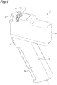
- the synthetic yarn splicer 1 is a so-called hand splicer.
- the synthetic yarn splicer 1 includes a main body 3 and a yarn splicing mechanism 5.
- the main body 3 is a casing which accommodates the yarn splicing mechanism 5.
- the main body 3 includes a first main body portion 3a and a second main body portion 3b.
- the main body 3 is formed in, for example, a substantially L shape in the side view.
- the first main body portion 3a is a portion which is gripped by an operator when the synthetic yarn splicer 1 is used.
- the first main body portion 3a has, for example, a substantially rectangular parallelepiped shape.
- the first main body portion 3a is provided with an operation portion 7.
- the operation portion 7 is a button which is operated when performing a splicing operation in the synthetic yarn splicer 1.
- the operation portion 7 is provided at a portion which is located within an operation range of an index finger when the first main body portion 3a is gripped by the operator at the side of one end portion (the side of the second main body portion 3b) of the first main body portion 3a in the longitudinal direction.
- the lower end portion of the first main body portion 3a (the other end portion of the longitudinal direction) is provided with a connection portion 9.
- a tube (not illustrated) supplying compressed air (fluid) (hereinafter, simply referred to as "air") is connected to the connection portion 9.
- the first main body portion 3a may accommodate a switch which is operated in synchronization with the operation of the operation portion 7 and components branching compressed air supplied through the connection portion 9.
- the second main body portion 3b is provided with the yarn splicing mechanism 5.
- the second main body portion 3b has, for example, a substantially rectangular parallelepiped shape.
- the second main body portion 3b is provided at one end portion of the first main body portion 3a.
- the second main body portion 3b is integrally formed with the first main body portion 3a so that a predetermined angle (for example, 90° or less) is formed between the longitudinal direction of the second main body portion 3b and the longitudinal direction of the first main body portion 3a.
- the second main body portion 3b exposes the yarn splicing mechanism 5.
- the second main body portion 3b accommodates a driving portion or the like (for example, a cylinder or the like) which drives a first clamping mechanism 20 and a second clamping mechanism 30 to be described later.
- the yarn splicing mechanism 5 includes a yarn splicing portion 10, the first clamping mechanism 20, and the second clamping mechanism 30.
- the first clamping mechanism 20 and the second clamping mechanism 30 are provided at a position that interposes a chamber 14 of the yarn splicing portion 10.
- the yarn splicing portion 10 includes a yarn splicing nozzle 12, a slit 13, a chamber (passage) 14, and an air flow passage 16.
- the yarn splicing nozzle 12 is a block body which is formed of metal or ceramic.
- the yarn splicing nozzle 12 includes an upper surface 12a, a pair of side surfaces 12b and 12c, and a lower surface 12d.
- a facing direction in which the upper surface 12a faces the lower surface 12d is a first direction Y (see FIG. 4 ).
- a facing direction in which a pair of side surfaces 12b and 12c faces each other is a second direction X (see FIG. 5 ).
- a direction orthogonal to the first direction Y and the second direction X is a third direction Z (see FIG. 4 ).
- the slit 13 is provided in the yarn splicing nozzle 12.
- the slit 13 is a portion which communicates with the chamber 14 and introduces a yarn into the chamber 14.
- the slit 13 is formed over the upper surface 12a of the yarn splicing nozzle 12 and the chamber 14.
- the slit 13 is disposed on a second line L2 (see FIG. 8 ) to be described later and extends in the first direction Y. That is, the insertion direction of the first yarn Y1 and the second yarn Y2 with respect to the slit 13 is the first direction Y.
- An upper portion of the slit 13 is provided with an inclined surface 15.
- the inclined surface 15 guides a yarn to the slit 13.
- the inclined surface 15 has a tapered shape which is narrowed from the upper surface 12a of the yarn splicing nozzle 12 toward the slit 13.
- the chamber 14 is a passage through which a first yarn Y1 and a second yarn Y2 are inserted. As illustrated in FIG. 5 , the chamber 14 penetrates one side surface 12b and the other side surface 12c of the yarn splicing nozzle 12. That is, the penetration direction of the chamber 14 is a facing direction (a second direction X) of the pair of side surfaces 12b and 12c and is orthogonal to the insertion direction of the first yarn Y1 and the second yarn Y2 with respect to the slit 13.
- the chamber 14 forms a space through which the first yarn Y1 and the second yarn Y2 are insertable.
- the chamber 14 has a circular shape when viewed from the side surfaces 12b and 12c. In the embodiment, the chamber 14 has a true circular shape.
- the diameter of the chamber 14 is equal to or larger than, for example, ⁇ 3.5 mm and equal to or smaller than ⁇ 6.0 mm.
- the air flow path 16 circulates air to be supplied to the chamber 14.
- the air flow path 16 includes an injection hole 16a which opens to the chamber 14.
- the injection hole 16a communicates the air flow path 16 with the chamber 14. Air is injected from the injection hole 16a to the chamber 14.
- the diameter of the injection hole 16a is desirably equal to or larger than ⁇ 1.0 mm and equal to or smaller than ⁇ 1.3 mm.
- the injection hole 16a is disposed on the first line L1 (see FIG. 8 ) in the chamber 14.
- a connection portion 18 is provided at the upstream side of the air flow path 16 (the opposite side to the injection hole 16a).
- a supply pipe or the like which supplies air is connected to the connection portion 18.
- the first clamping mechanism 20 includes a support portion 22 and a clamping portion 23.
- the first clamping mechanism 20 clamps a yarn inserted through the chamber 14 of the yarn splicing portion 10.
- the support portion 22 has a rectangular parallelepiped shape (prismatic shape). As illustrated in FIG. 5 , the support portion 22 includes a pair of facing main surfaces 22a arid 22b and a pair of facing side surfaces 22c and 22d.
- the side surface 22d is a surface which faces the side surface 12b in the yarn splicing nozzle 12.
- the support portion 22 holds the clamping portion 23.
- the support portion 22 is provided to be swingable. Specifically, as illustrated in FIG. 2 , a base end portion of the support portion 22 (one end portion of the longitudinal direction) is provided with a shaft 21.
- the shaft 21 is fixed to a frame (not illustrated) or the like.
- the support portion 22 swings about the shaft 21.
- the support portion 22 moves between a second position P2 (see FIG. 6B ) in which a front end portion (the other end portion of the longitudinal direction) moves close to the yarn splicing portion 10 and a first position P1 (see FIG. 6A ) in which the front end portion moves away from the yarn splicing portion 10 in relation to the second position P2.
- the support portion 22 moves by the driving of, for example, a driving portion (not illustrated) such as a cylinder.
- a driving portion such as a cylinder.
- one end portion of the longitudinal direction provided with the shaft 21 in the support portion 22 will be referred to as a base end portion and the other end portion of the longitudinal direction opposite to the one end portion will be referred to as a front end portion.
- the support portion 22 is provided with a concave portion 25.
- the concave portion 25 is provided at the side of the front end portion of the support portion 22.
- the concave portion 25 opens to the main surface 22a and the pair of side surfaces 22c and 22d of the support portion 22.
- the concave portion 25 exposes a part of the clamping portion 23.
- the concave portion 25 has a rectangular shape when viewed from the main surface 22a of the support portion 22.
- the concave portion 25 has a rectangular shape when viewed from the side surface 22c of the support portion 22.
- the support portion 22 includes a support surface 27a which slidably supports a second clamping member 26 (a first clamping member 24) to be described later in the clamping portion 23.
- the support surface 27a is provided at a center portion in the facing direction of the pair of side surfaces 22c and 22d of the support portion 22.
- the support surface 27a has a shape (a semi-circular shape) which is curved in a convex shape downward in response to the shape of the outer peripheral surface of the second clamping member 26 (the first clamping member 24).
- the support surface 27a extends in the longitudinal direction of the support portion 22.
- the support portion 22 includes a first contact surface 27b and a second contact surface 27c at a position interposing the support surface 27a in the facing direction of the pair of side surfaces 22c and 22d (the facing direction of the first clamping mechanism 20 and the second clamping mechanism 30).
- the first contact surface 27b and the second contact surface 27c constitute a bottom surface of the concave portion 25.
- the first contact surface 27b is a surface which is able to contact the first yarn Y1 and the second yarn Y2 clamped by the clamping portion 23.
- a contactable state includes a case in which the first contact surface 27b contacts the first yarn Y1 and the second yarn Y2 clamped by the clamping portion 23 and a case in which the first contact surface 27b does not contact the first yarn Y1 and the second yarn Y2.
- the second contact surface 27c is a surface which contacts the first yarn Y1 and the second yarn Y2 clamped by the clamping portion 23. As illustrated in FIG. 2 , the first contact surface 27b and the second contact surface 27c are provided at a position in which at least the first clamping member 24 and the second clamping member 26 contact.
- the first contact surface 27b is a flat surface which is continuous to one end of the support surface 27a (an end at the side of the side surface 22c).
- the second contact surface 27c is a flat surface which is continuous to the other end of the support surface 27a (an end at the side of the side surface 22d). That is, respective surfaces are provided in order of the second contact surface 27c, the support surface 27a, and the first contact surface 27b from the yarn splicing portion 10 when viewed from the facing direction of the pair of main surfaces 22a and 22b of the support portion 22. That is, the second contact surface 27c is disposed between the yarn splicing portion 10 and the clamping portion 23.
- the second contact surface 27c is located at the inside of the facing direction of the first clamping mechanism 20 and the second clamping mechanism 30 facing each other with the yarn splicing portion 10 interposed therebetween and the first contact surface 27b is located at the outside of the facing direction.
- the first contact surface 27b is substantially parallel to the main surfaces 22a and 22b.
- the first contact surface 27b is provided over the support surface 27a and the side surface 22c.
- the second contact surface 27c is substantially parallel to the main surfaces 22a and 22b.
- the second contact surface 27c is provided over the support surface 27a and the side surface 22d.
- the first contact surface 27b and the second contact surface 27c are located at the same height position in the facing direction of the pair of main surfaces 22a and 22b of the support portion 22.
- An angle of about 90° is formed between the second contact surface 27c and the side surface 22d. It is desirable to polish a surface of a top of a corner between the second contact surface 27c and the side surface 22d. In this configuration, it is possible to suppress the damage of the first yarn Y1 and the second yarn Y2 when the first yarn Y1 and the second yarn Y2 are separated from the top.
- the clamping portion 23 includes the first clamping member 24 and the second clamping member 26.
- Each of the first clamping member 24 and the second clamping member 26 is formed in a columnar shape.
- Each of the first clamping member 24 and the second clamping member 26 is formed of, for example, metal such as SUS having abrasion resistance. The diameter of each of the first clamping member 24 and the second clamping member 26 may be appropriately set.
- the first clamping member 24 and the second clamping member 26 are disposed at the support portion 22 so that respective end surfaces face each other. Specifically, the first clamping member 24 is disposed at the side of the front end portion of the support portion 22 and the second clamping member 26 is disposed at the side of the base end portion of the support portion 22 in relation to the first clamping member 24.
- the first clamping mechanism 20 holds a yarn by clamping the yarn between the end surface of the first clamping member 24 and the end surface of the second clamping member 26 in the clamping portion 23.
- the first clamping member 24 may be fixed to the support portion 22 and may be provided to be movable (slidable on the support surface 27a) in the facing direction of the first clamping member 24 and the second clamping member 26 (hereinafter, simply referred to as the "facing direction").
- a part of the second clamping member 26 is accommodated in the support portion 22 and a part of the second clamping member 26 is exposed in the concave portion 25 of the support portion 22.
- the second clamping member 26 is movably provided in the support portion 22.
- the second clamping member 26 moves in the facing direction.
- the second clamping member 26 is biased toward the first clamping member 24 by a biasing member (not illustrated) such as a spring. That is, the end surfaces of the second clamping member 26 and the first clamping member 24 are in contact with each other by a biasing force of a biasing member in a state in which a force other than the biasing member is not applied to the second clamping member 26.
- the second clamping member 26 moves in synchronization with the movement of the support portion 22.
- the second clamping member 26 moves in a direction moving away from the first clamping member 24 by the movement of the support portion 22 from the second position P2 (see FIG 6B ) to the first position P1 (see FIG. 6A ).
- the second clamping member 26 can be pressed down in a direction opposite to the biasing direction of the biasing member by a cam mechanism (not illustrated) or the like when the support portion 22 moves from the second position P2 to the first position P1. Accordingly, a gap (space) is formed between the first clamping member 24 and the second clamping member 26 in the clamping portion 23.
- the movement of the second clamping member 26 may not be synchronized with the movement of the support portion 22.
- the second clamping mechanism 30 includes a support portion 32 and a clamping portion 33.
- the second clamping mechanism 30 clamps a yarn inserted through the chamber 14 of the yarn splicing portion 10.
- the support portion 32 has a rectangular parallelepiped shape (prismatic shape). As illustrated in FIG. 5 , the support portion 32 includes a pair of facing main surfaces 32a and 32b and a pair of facing side surfaces 32c and 32d.
- the side surface 32d is a surface which faces the side surface 12c of the yarn splicing nozzle 12.
- the support portion 32 holds the clamping portion 33.
- the support portion 32 is provided to be swingable. Specifically, as illustrated in FIG. 2 , a base end portion of the support portion 32 (one end portion of the longitudinal direction) is provided with a shaft 31.
- the shaft 31 is fixed to a frame (not illustrated) or the like.
- the support portion 32 swings about the shaft 31.
- the support portion 32 moves between a second position P2 (see FIG. 6B ) in which a front end portion (the other end portion of the longitudinal direction) moves close to the yarn splicing portion 10 and a first position P1 (see FIG. 6A ) in which the front end portion moves away from the yarn splicing portion 10 in relation to the second position P2.
- the support portion 32 moves by the driving of, for example, a driving portion (not illustrated) such as a cylinder.
- the driving portion may be the same as the driving portion that drives the support portion 22 or may be separately provided.
- one end portion of the longitudinal direction provided with the shaft 31 in the support portion 32 will be referred to as a base end portion and the other end portion of the longitudinal direction opposite to the one end portion will be referred to as a front end portion.
- the support portion 32 is provided with a concave portion 35.
- the concave portion 35 is provided at the side of the front end portion of the support portion 32.
- the concave portion 35 opens to the main surface 32a and the pair of side surfaces 32c and 32d of the support portion 32.
- the concave portion 35 exposes a part of the clamping portion 33.
- the concave portion 35 has a rectangular shape when viewed from the main surface 32a of the support portion 32.
- the concave portion 35 has a rectangular shape when viewed from the side surfaces 32c and 32d of the support portion 32.
- the support portion 32 includes a support surface 37a which slidably supports the second clamping member 36 (the first clamping member 34) to be described later in the clamping portion 33.
- the support surface 37a is provided at a center portion of the facing direction of the pair of side surfaces 32c and 32d of the support portion 32.
- the support surface 37a has a shape (a semi-circular shape) which is curved in a convex shape downward in response to the shape of the outer peripheral surface of the second clamping member 36 (the first clamping member 34).
- the support surface 37a extends in the longitudinal direction of the support portion 32.
- the support portion 32 includes a first contact surface 37b and a second contact surface 37c at a position interposing the support surface 37a in the facing direction of the pair of side surfaces 32c and 32d.
- the first contact surface 37b and the second contact surface 37c constitute a bottom surface of the concave portion 35.
- the first contact surface 37b is a surface which is able to contact the first yarn Y1 and the second yarn Y2 clamped by the clamping portion 33.
- the second contact surface 37c is a surface which contacts the first yarn Y1 and the second yarn Y2 clamped by the clamping portion 33.
- the first contact surface 37b and the second contact surface 37c are provided at a position in which at least the first clamping member 34 and the second clamping member 36 contact.
- the first contact surface 37b is a flat surface which is continuous to one end of the support surface 37a (an end at the side of the side surface 32c).
- the second contact surface 37c is a flat surface which is continuous to the other end of the support surface 37a (an end at the side of the side surface 32d). That is, respective surfaces are provided in order of the second contact surface 37c, the support surface 37a, and the first contact surface 37b from the yarn splicing portion 10 when viewed from the facing direction of the pair of main surfaces 32a and 32b of the support portion 32. That is, the second contact surface 37c is disposed between the yarn splicing portion 10 and the clamping portion 33.
- the second contact surface 37c is located at the inside of the facing direction of the first clamping mechanism 20 and the second clamping mechanism 30 facing each other with the yarn splicing portion 10 interposed therebetween and the first contact surface 37b is located at the outside of the facing direction.
- the first contact surface 37b is substantially parallel to the main surfaces 32a and 32b.
- the first contact surface 37b is provided over the support surface 37a and the side surface 32c.
- the second contact surface 37c is substantially parallel to the main surfaces 32a and 32b.
- the second contact surface 37c is provided over the support surface 37a and the side surface 32d.
- the first contact surface 37b and the second contact surface 37c are located at the same height position in the facing direction of the pair of main surfaces 32a and 32b of the support portion 32.
- An angle of about 90° is formed between the second contact surface 37c and the side surface 32d. It is desirable to polish a surface of a top of a corner formed by the second contact surface 37c and the side surface 32d.
- the clamping portion 33 includes the first clamping member 34 and the second clamping member 36.
- Each of the first clamping member 34 and the second clamping member 36 is formed in a columnar shape.
- Each of the first clamping member 34 and the second clamping member 36 is formed of, for example, metal such as SUS having abrasion resistance. The diameter of each of the first clamping member 34 and the second clamping member 36 may be appropriately set.
- the first clamping member 34 and the second clamping member 36 are disposed at the support portion 32 so that respective end surfaces face each other. Specifically, the first clamping member 34 is disposed at the side of the front end portion of the support portion 32 and the second clamping member 36 is disposed at the side of the base end portion of the support portion 32 in relation to the first clamping member 34.
- the second clamping mechanism 30 holds a yarn by clamping the yarn between the end surface of the first clamping member 34 and the end surface of the second clamping member 36 in the clamping portion 33.
- the first clamping member 34 may be fixed to the support portion 32 and may be provided to be movable in the facing direction of the first clamping member 34 and the second clamping member 36 (to be slidable on the support surface 37a).
- a part of the second clamping member 36 is accommodated in the support portion 32 and a part of the second clamping member 36 is exposed in the concave portion 35 of the support portion 32.
- the second clamping member 36 is movably provided in the support portion 32.
- the second clamping member 36 moves in the facing direction.
- the second clamping member 36 is biased toward the first clamping member 34 by a biasing member (not illustrated) such as a spring. That is, the end surfaces of the second clamping member 36 and the first clamping member 34 contact each other by a biasing force of a biasing member in a state in which a force other than the biasing member is not applied to the second clamping member 36.
- the second clamping member 36 moves in synchronization with the movement of the support portion 32.
- the second clamping member 36 moves in a direction moving away from the first clamping member 34 by the movement of the support portion 32 from a second position P2 (see FIG. 6B ) to a first position P1 (see FIG. 6A ).
- the second clamping member 36 is pressed down in a direction opposite to the biasing direction of the biasing member by a cam mechanism (not illustrated) or the like when the support portion 32 moves from the second position P2 to the first position P1. Accordingly, a gap (space) is formed between the first clamping member 34 and the second clamping member 36 in the clamping portion 33.
- the movement of the second clamping member 36 may not be synchronized with the movement of the support portion 32.
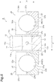
- the first clamping mechanism 20 and the second clamping mechanism 30 clamp the first yarn Y1 and the second yarn Y2 so that the line L connecting the pair of clamping positions CP1 and CP2 of the first yarn Y1 and the second yarn Y2 is located at an area (a predetermined area) A in the chamber 14 at the second position P2.
- the clamping position CP1 is a position of each of the end portions of the first yarn Y1 and the second yarn Y2 (one end portion between the first clamping mechanism 20 and the second clamping mechanism 30) clamped by the first clamping member 24 and the second clamping member 26 and contacting the second contact surface 27c in the first clamping mechanism 20.
- the clamping position CP2 is a position of each of the end portions of the first yarn Y1 and the second yarn Y2 (the other end portion between the first clamping mechanism 20 and the second clamping mechanism 30) clamped by the first clamping member 34 and the second clamping member 36 and contacting the second contact surface 37c in the second clamping mechanism 30.
- the area A is located at the side of the lower surface 12d (the side opposite to the slit 13) with respect to the first line L1 following the third direction Z of the yarn splicing nozzle 12 and passing through the center C of the chamber 14 and is located at the side opposite to the injection hole 16a with respect to the second line L2 following the first direction Y and passing through the center C. That is, the area A is located inside a fan-shaped area in which a center angle formed between the first line L1 and the second line L2 is 90°.
- the area A is an annular area between a first circular arc CA1 which is distant from the center by 0.5 mm and a second circular arc CA2 which is distant from the inner peripheral surface 14a of the chamber 14 by 0.3 mm. That is, a distance M1 between the center C and an intersection point P100 between the first circular arc CA1 and the first line L1 is 0.5 mm. A distance M2 between the center C and an intersection point P200 between the first circular arc CA1 and the second line L2 is 0.5 mm. A distance M3 between the inner peripheral surface 14a and an intersection point P300 between the second circular arc CA2 and the first line L1 is 0.3 mm.
- a distance M4 between the inner peripheral surface 14a and an intersection point P400 between the second circular arc CA2 and the second line L2 is 0.3 mm.
- a distance between the first circular arc CA1 and the second circular arc CA2 in the radial direction of the chamber 14 is constant.
- the pair of clamping positions CP1 and CP2 of the first yarn Y1 and the second yarn Y2 in the first clamping mechanism 20 and the second clamping mechanism 30 can be adjusted by adjusting the positions of the yarn splicing portion 10 and/or the support portion 22 and the support portion 32.
- the positions of the pair of clamping positions CP1 and CP2 in the first direction Y can be adjusted by changing the positions of the support portion 22 and the support portion 32.
- the positions of the pair of clamping positions CP1 and CP2 in the third direction Z can be adjusted by changing the position of the yarn splicing portion 10.
- the first yarn Y1 and the second yarn Y2 are set on the synthetic yarn splicer 1. Specifically, the first yarn Y1 and the second yarn Y2 are located in the chamber 14 through the slit 13 of the yarn splicing portion 10 and are disposed on the first clamping mechanism 20 and the second clamping mechanism 30 located at the first position P1. More specifically, the first yarn Y1 and the second yarn Y2 are disposed between the first clamping member 24 and the second clamping member 26 of the first clamping mechanism 20 and are disposed between the first clamping member 34 and the second clamping member 36 of the second clamping mechanism 30.
- first yarn Y1 and the second yarn Y2 are placed on the first contact surface 27b and the second contact surface 27c of the first clamping mechanism 20 and are placed on the first contact surface 37b and the second contact surface 37c of the second clamping mechanism 30.
- the operation portion 7 is operated (pressed down). Accordingly, in the synthetic yarn splicer 1, the driving portion is operated so that the first clamping mechanism 20 and the second clamping mechanism 30 are operated.
- first yarn Y1 and the second yarn Y2 are clamped by the first clamping member 24 and the second clamping member 26 of the first clamping mechanism 20. Further, the first yarn Y1 and the second yarn Y2 are clamped by the first clamping member 34 and the second clamping member 36 of the second clamping mechanism 30. Then, as illustrated in FIG. 6B , the first clamping mechanism 20 and the second clamping mechanism 30 move from the first position P1 to the second position P2. Accordingly, as illustrated in FIG. 7 , the first yarn Y1 and the second yarn Y2 are held between the clamping portion 23 and the clamping portion 33 in a loosened state.
- first yarn Y1 and the second yarn Y2 are held while contacting at least the second contact surface 27c and the second contact surface 37c.
- the line L connecting the pair of clamping positions CP1 and CP2 of the first yarn Y1 and the second yarn Y2 is located at the area A of the chamber 14.
- the operation portion 7 when the operation portion 7 is operated, air is injected from the injection hole 16a to the chamber 14 through the air flow path 16. Accordingly, the first yarn Y1 and the second yarn Y2 located inside the chamber 14 are spliced by the action of air to form an entangled portion.
- the operation of the operation portion 7 is cancelled. Accordingly, in the synthetic yarn splicer 1, the injection of air from the injection hole 16a to the chamber 14 is stopped and the first clamping mechanism 20 and the second clamping mechanism 30 are operated.
- the first clamping mechanism 20 and the second clamping mechanism 30 move from the second position P2 to the first position P1.
- the second clamping member 26 of the first clamping mechanism 20 moves in a direction moving away from the first clamping member 24 and the clamping of the first yarn Y1 and the second yarn Y2 by the first clamping member 24 and the second clamping member 26 is cancelled.
- the second clamping member 36 moves in a direction moving away from the first clamping member 34 and the clamping of the first yarn Y1 and the second yarn Y2 by the first clamping member 34 and the second clamping member 36 is cancelled.
- the clamping of the first yarn Y1 and the second yarn Y2 by the first clamping member 24 and the second clamping member 26 may be cancelled after the first clamping mechanism 20 moves from the second position P2 to the first position P1.
- the clamping of the first yarn Y1 and the second yarn Y2 by the first clamping member 34 and the second clamping member 36 may be cancelled after the second clamping mechanism 30 moves from the second position P2 to the first position P1.
- the first clamping mechanism 20 and the second clamping mechanism 30 clamp the first yarn Y1 and the second yarn Y2 so that the line L connecting the pair of clamping positions CP1 and CP2 of the first yarn Y1 and the second yarn Y2 is located in an area A of the chamber 14 when viewed from the second direction X.
- the area A is, as illustrated in FIG. 8 , an area which is defined by the first circular arc CA1 and the second circular arc CA2.
- FIGS. 9 , 10A to 10C , 11A to 11C , 12A to 12C , and 13A to 13C will be described with reference to FIGS. 9 , 10A to 10C , 11A to 11C , 12A to 12C , and 13A to 13C .
- a third line L3 is a line which is separated by a distance M11 from the first line L1 to the upper surface 12a of the yarn splicing nozzle 12 and extends in parallel to the first line L1.
- a fourth line L4 is a line which is separated by a distance M12 from the first line L1 to the lower surface 12d of the yarn splicing nozzle 12 and extends in parallel to the first line L1.
- a fifth line L5 is a line which is separated by a distance M13 from the second line L2 to the injection hole 16a and extends in parallel to the second line L2.
- a sixth line L6 is a line which is separated by a distance M14 from the second line L2 to the side opposite to the injection hole 16a and extends in parallel to the second line L2.
- the distances M11 to M14 are 1 mm.
- An intersection point between the third line L3 and the fifth line L5 is set as P11.
- An intersection point between the third line L3 and the second line L2 is set as P12.
- An intersection point between the third line L3 and the sixth line L6 is set as P13.
- An intersection point between the first line L1 and the fifth line L5 is set as P14.
- An intersection point between the first line L1 and the second line L2 is set as P15.
- the intersection point P15 corresponds to the center C of the chamber 14.
- An intersection point between the first line L1 and the sixth line L6 is set as P16.
- An intersection point between the fourth line L4 and the fifth line L5 is set as P17.
- An intersection point between the fourth line L4 and the second line L2 is set as P18.
- intersection point between the fourth line L4 and the sixth line L6 is set as P19.
- the intersection point P16, the intersection point P18, and the intersection point P19 are located in the area A. Furthermore, in FIG. 9 , a positional relationship between the area A and each of the intersection points P11 to P19 can be changed in response to the diameter of the chamber 14.
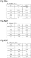
- FIGS. 10A to 10C , 11A to 11C , 12A to 12C , and 13A to 13C a measurement for three types of yarns (a yarn A to a yarn C) having different thicknesses or number of filaments was performed by using TENSORAPID4 (trade name) manufactured by USTER. Each yarn is a pre-oriented yarn (POY).
- FIGS. 10A to 10C show a result of a configuration in which the diameter of the chamber 14 is ⁇ 6.0 mm and the diameter of the injection hole 16a is ⁇ 1.3 mm.
- FIGS. 11A to 11C show a result of a configuration in which the diameter of the chamber 14 is ⁇ 3.5 mm and the diameter of the injection hole 16a is ⁇ 1.0 mm.
- FIGS. 13A to 13C show a result of a configuration in which the diameter of the chamber 14 is ⁇ 6.0 mm and the diameter of the injection hole 16a is ⁇ 1.0 mm.
- FIGS. 13A to 13C show a result of a configuration in which the diameter of the chamber 14 is ⁇ 3.5 mm and the diameter of the injection hole 16a is ⁇ 1.3 mm.
- FIGS. 10A to 10C , 11A to 11C , 12A to 12C , and 13A to 13C show a tensile elongation decrease amount (%) from a reference value by using a tensile elongation measurement value of a synthetic fiber without an entangled portion as a reference value.
- "-" illustrates a state in which the entangled portion is not formed.
- " ⁇ " illustrates a state in which the yarn is pulled out and the coupling cannot be maintained when a tension is applied to the yarn although the entangled portion is formed.
- a yarn A is a yarn of 40[dtex]-10[f] having a reference value of 63.0%.
- the tensile elongation decrease amount (%) was relatively small at the intersection point P15, the intersection point P16, the intersection point P18, and the intersection point P19 as compared with the intersection points P11 to P14 and the intersection point P17.
- a yarn B is a yarn of 88[dtex]-72[f] having a reference value of 130.1%.
- the tensile elongation decrease amount (%) was relatively small at the intersection point P15, the intersection point P16, the intersection point P18, and the intersection point P19 as compared with the intersection points P11 to P14 and the intersection point P17.
- a yarn C is a yarn of 135[dtex]-72[f] having a reference value of 127.1%.
- the tensile elongation decrease amount (%) was small at the intersection point P16, the intersection point P18, and the intersection point P19 as compared with the intersection points P11 to P15 and the intersection point P17.
- a yarn A is a yarn of 40[dtex]-10[f] having a reference value of 63.1%.
- the tensile elongation decrease amount (%) was relatively small at the intersection point P14, the intersection point P15, the intersection point P16, and the intersection point P19 as compared with the intersection points P11 to P13, the intersection point P17, and the intersection point P18.
- FIG. 12A the tensile elongation decrease amount (%) was relatively small at the intersection point P14, the intersection point P15, the intersection point P16, and the intersection point P19 as compared with the intersection points P11 to P13, the intersection point P17, and the intersection point P18.
- a yarn B is a yarn of 88[dtex]-72[f] having a reference value of 130.8%.
- the tensile elongation decrease amount (%) was relatively small at the intersection points P15 to P19 as compared with the intersection points P11 to P14.
- the tensile elongation decrease amount (%) was relatively small at the intersection point P15, the intersection point P16, the intersection point P18, and the intersection point P19 as compared with the intersection points P11 to P14 and the intersection point P17.
- a yarn C is a yarn of 135[dtex]-72[f] having a reference value of 130.0%.
- the tensile elongation decrease amount (%) was relatively small at the intersection point P13, the intersection point P16, the intersection point P18, and the intersection point P19 as compared with the intersection point P11, the intersection point P12, the intersection point P14, the intersection point P15, and the intersection point P17.
- the tensile elongation decrease amount (%) is small in any case. For that reason, in the synthetic yarn splicer 1, it was found that a decrease in tensile elongation could be suppressed by locating the line L connecting the clamping positions CP1 and CP2 at the area A. Furthermore, since the tensile elongation value is generally different when the type of yarn (for example, a thickness or the number of filaments) is different, the allowed tensile elongation decrease amount (%) is also different.
- the diameter of the chamber 14 is equal to or larger than ⁇ 3.5 mm and equal to or smaller than ⁇ 6.0 mm and the diameter of the injection hole 16a is equal to or larger than ⁇ 1.0 mm and equal to or smaller than ⁇ 1.3 mm.
- the synthetic yarn splicer 1 it is possible to suppress a change in tensile elongation decrease amount while suppressing a decrease in tensile elongation of the entangled portion.
- the first clamping mechanism 20 includes the clamping portion 23 which includes the first clamping member 24 and the second clamping member 26 respectively clamping the first yarn Y1 and the second yarn Y2.
- the second clamping mechanism 30 includes the clamping portion 33 which includes the first clamping member 34 and the second clamping member 36 respectively clamping the first yarn Y1 and the second yarn Y2.
- the clamping positions CP1 and CP2 of the first yarn Y1 and the second yarn Y2 can be accurately set. Accordingly, in the synthetic yarn splicer 1, the line L connecting the pair of clamping positions CP1 and CP2 can be reliably located in the area A.
- the first clamping mechanism 20 includes the support portion 22 which supports the clamping portion 23.
- the second clamping mechanism 30 includes the support portion 32 which supports the clamping portion 33.
- the support portion 22 is disposed between the yarn splicing portion 10 and the clamping portion 23 and includes the second contact surface 27c in which the first yarn Y1 and the second yarn Y2 clamped by the clamping portion 23 contact.
- the support portion 32 is disposed between the yarn splicing portion 10 and the clamping portion 33 and includes the second contact surface 37c in which the first yarn Y1 and the second yarn Y2 clamped by the clamping portion 33 contact.
- the first yarn Y1 and the second yarn Y2 can be supported by the second contact surface 27c and the second contact surface 37c.
- the clamping positions CP1 and CP2 of the first yarn Y1 and the second yarn Y2 can be more accurately set.
- the line L connecting the pair of clamping positions CP1 and CP2 can be reliably located in the area A.
- a shape illustrated in FIG. 1 has been described as the shape of the main body 3.
- the shape of the main body 3 is not limited to the shape illustrated in FIG. 1 .
- first clamping members 24 and 34 and the second clamping members 26 and 36 are formed in a columnar shape, that is, the cross-sections of the first clamping members 24 and 34 and the second clamping members 26 and 36 are formed in a circular shape has been described.
- first clamping member and the second clamping member are not limited to the columnar shape as long as the yarn can be clamped, but may be formed in various shapes (for example, prismatic shapes or the like).
- the support portions 22 and 32 may move in a direction moving close to each other and moving away from each other, for example, in a substantially parallel state.
- the slit 13 may be disposed at the side of the upper surface 12a of the yarn splicing nozzle 12 in relation to the first line L1.
- the area A is an annular area between the first circular arc CA1 which is distant from the center by 0.5 mm and the second circular arc CA2 which is distant from the inner peripheral surface 14a of the chamber 14 by 0.3 mm has been described.
- the area may be at least an area which is located at the side opposite to the slit 13 with respect to the first line L1 and is located at the side opposite to the injection hole 16a with respect to the second line L2.
- first yarn Y1 and the second yarn Y2 are disposed on the first clamping mechanism 20 and the second clamping mechanism 30 located at the second position P2, the first clamping mechanism 20 and the second clamping mechanism 30 are moved from the second position P2 to the first position P1, the first clamping mechanism 20 and the second clamping mechanism 30 are moved from the first position P1 to the second position P2, and air is injected from the injection hole 16a to the chamber 14 to form an entangled portion.
- the diameter of the chamber 14 and the diameter of the injection hole 16a are changeable by replacing the yarn splicing portion 10.
- the synthetic yarn splicer 1 is a hand splicer used while being gripped by an operator.
- the synthetic yarn splicer may be provided in an apparatus or the like.
- SECOND CONTACT SURFACE 30...SECOND CLAMPING MECHANISM, 32...SUPPORT PORTION, 33...CLAMPING PORTION, 34...FIRST CLAMPING MEMBER, 36...SECOND CLAMPING MEMBER, 37c...SECOND CONTACT SURFACE, A...AREA, C...CENTER, CA1...FIRST CIRCULAR ARC, CA2...SECOND CIRCULAR ARC, CP1,CP2...CLAMPING POSITION, L...LINE, L1...FIRST LINE, L2...SECOND LINE, Y1...FIRST YARN (ONE YARN), Y2...SECOND YARN (OTHER YARN).
Landscapes
- Engineering & Computer Science (AREA)
- Textile Engineering (AREA)
- Spinning Or Twisting Of Yarns (AREA)
- Yarns And Mechanical Finishing Of Yarns Or Ropes (AREA)
Claims (4)
- Dispositif d'épissage de fils synthétiques (1) qui épisse un premier fil (Y1) et l'autre fil (Y2) formés de fibres synthétiques, comprenant :une partie d'épissage de fils (10) qui comporte un passage (14) qui forme un espace à travers lequel le premier fil (Y1) et l'autre fil (Y2) peuvent être insérés, une fente (13) qui communique avec le passage (14) et permet au premier fil (Y1) et à l'autre fil (Y2) d'être insérables dans le passage (14) à partir d'une direction d'insertion orthogonale à une direction de pénétration du passage (14), et un trou d'injection (16a) qui s'ouvre sur le passage (14) et injecte un fluide ; etune paire de mécanismes de serrage (20, 30) qui est prévue à une position interposant le passage (14) de la partie d'épissage de fils (10) dans la direction de pénétration du passage (14) et serre chacun du premier fil (Y1) et de l'autre fil (Y2) insérés à travers l'espace,dans lequel le passage (14) a une forme circulaire lorsqu'on regarde depuis la direction de pénétration du passage (14),dans lequel le trou d'injection (16a) est disposé sur une première ligne (L1) qui est orthogonale à la direction de pénétration du passage (14) et à la direction d'insertion et passe par un centre (C) du passage (14),dans lequel la paire de mécanismes de serrage (20, 30) serre le premier fil (Y1) et l'autre fil (Y2) de sorte qu'une ligne (L) reliant une paire de positions de serrage (CP1, CP2) du premier fil (Y1) et de l'autre fil (Y2) soit située dans une zone prédéterminée (A) du passage (14) lorsqu'on regarde depuis la direction de pénétration du passage (14), etdans lequel la zone prédéterminée (A) est une zone qui est située au niveau du côté opposé à la fente (13) par rapport à la première ligne (L1) et est située au niveau du côté opposé au trou d'injection (16a) par rapport à une deuxième ligne (L2) suivant la direction d'insertion et passant par le centre (C) caractérisé en ce quela zone prédéterminée (A) est une zone entre un premier arc de cercle (CA1) qui est éloigné du centre (C) de 0,5 mm et un deuxième arc de cercle (CA2) qui est éloigné de la surface périphérique interne (14a) du passage (14) de 0,3 mm.
- Dispositif d'épissage de fils synthétiques (1) selon la revendication 1,
dans lequel un diamètre du passage (14) est supérieur ou égal à φ3,5 mm et inférieur ou égal à φ6,0 mm, et
dans lequel un diamètre du trou d'injection (16a) est supérieur ou égal à φ1,0 mm et inférieur ou égal à φ1,3 mm. - Dispositif d'épissage de fils synthétiques (1) selon l'une quelconque des revendications 1 ou 2,
dans lequel chacun de la paire de mécanismes de serrage (20, 30) comporte une partie de serrage (23, 33) comportant une paire d'éléments de serrage (24, 26, 34, 36) serrant chacun du premier fil (Y1) et de l'autre fil (Y2). - Dispositif d'épissage de fils synthétiques (1) selon la revendication 3,
dans lequel chacun de la paire de mécanismes de serrage (20, 30) comporte une partie de support (22, 32) supportant la partie de serrage (23, 33), et
dans lequel la partie de support (22, 32) est disposée entre la partie d'épissage de fils (10) et la partie de serrage (23, 33) et comporte une surface de contact (27c, 37c) en contact avec le premier fil (Y1) et l'autre fil (Y2) serrés par la partie de serrage (23, 33).
Applications Claiming Priority (1)
| Application Number | Priority Date | Filing Date | Title |
|---|---|---|---|
| JP2018076688 | 2018-04-12 |
Publications (2)
| Publication Number | Publication Date |
|---|---|
| EP3553007A1 EP3553007A1 (fr) | 2019-10-16 |
| EP3553007B1 true EP3553007B1 (fr) | 2021-06-09 |
Family
ID=66101912
Family Applications (1)
| Application Number | Title | Priority Date | Filing Date |
|---|---|---|---|
| EP19167520.6A Active EP3553007B1 (fr) | 2018-04-12 | 2019-04-05 | Dispositif d'épissage de fil synthétique |
Country Status (4)
| Country | Link |
|---|---|
| EP (1) | EP3553007B1 (fr) |
| JP (1) | JP7202956B2 (fr) |
| CN (1) | CN110371792B (fr) |
| TW (1) | TWI784158B (fr) |
Families Citing this family (3)
| Publication number | Priority date | Publication date | Assignee | Title |
|---|---|---|---|---|
| EP3553009B1 (fr) * | 2018-04-12 | 2022-03-30 | TMT Machinery, Inc. | Épisseur de fil synthétique |
| JP7026560B2 (ja) * | 2018-04-12 | 2022-02-28 | Tmtマシナリー株式会社 | 合繊糸用スプライサ |
| CN112981627A (zh) * | 2021-02-05 | 2021-06-18 | 温岭群豪纱线捻接技术有限公司 | 纱线捻接器上的夹纱器及由其所构成的接线组件 |
Family Cites Families (16)
| Publication number | Priority date | Publication date | Assignee | Title |
|---|---|---|---|---|
| US4002012A (en) * | 1975-05-21 | 1977-01-11 | Champion International Corporation | Method and apparatus for splicing thermoplastic textile yarn |
| JPS6131010Y2 (fr) * | 1979-01-31 | 1986-09-09 | ||
| JPS5939662A (ja) * | 1982-08-27 | 1984-03-05 | Teijin Seiki Co Ltd | 糸条の結合装置 |
| JPS60144281A (ja) * | 1983-12-27 | 1985-07-30 | Ishikawa Seisakusho:Kk | ポリエステル未延伸マルチフイラメント糸の糸継ぎ方法とその装置 |
| DE3408668A1 (de) * | 1984-03-09 | 1985-09-12 | W. Schlafhorst & Co, 4050 Mönchengladbach | Vorbereitungsaggregat zum vorbereiten eines fadenendes |
| US4642228A (en) | 1985-07-24 | 1987-02-10 | Angel Sanjurjo | Fluxing system for reactors for production of silicon |
| DE4032512C1 (fr) * | 1990-10-12 | 1992-01-16 | Karl Mayer Textilmaschinenfabrik Gmbh, 6053 Obertshausen, De | |
| JP2809071B2 (ja) * | 1993-11-05 | 1998-10-08 | 村田機械株式会社 | 糸端の解撚ノズル及び糸端の解撚方法 |
| DE19827870C1 (de) * | 1998-06-23 | 1999-10-07 | Saurer Allma Gmbh | Verfahren zur Herstellung eines abwechselnd S- und Z-Drehungen aufweisenden Filamentgarnes |
| DE10202781A1 (de) * | 2002-01-25 | 2003-07-31 | Schlafhorst & Co W | Vorrichtung zum pneumatischen Verbinden von Garnen |
| CN100410433C (zh) * | 2002-09-09 | 2008-08-13 | 村田机械株式会社 | 接头装置及接头方法 |
| US6907721B2 (en) * | 2002-12-19 | 2005-06-21 | Invista North America, S.A.R.L. | Spliced yarn and method for forming the same |
| JP5192482B2 (ja) * | 2007-03-22 | 2013-05-08 | 株式会社島精機製作所 | スプライスヘッド、糸継ぎ装置および糸継ぎ方法 |
| JP2009143718A (ja) * | 2007-12-18 | 2009-07-02 | Murata Mach Ltd | スプライサーノズル |
| JP2009190853A (ja) * | 2008-02-15 | 2009-08-27 | Murata Mach Ltd | スプライサユニット及び糸巻取機 |
| JP2015174764A (ja) * | 2014-03-18 | 2015-10-05 | 村田機械株式会社 | 撚掛ノズル、糸継ノズル構造体、糸継装置、巻取ユニット及び繊維機械 |
-
2019
- 2019-04-03 JP JP2019071383A patent/JP7202956B2/ja active Active
- 2019-04-05 EP EP19167520.6A patent/EP3553007B1/fr active Active
- 2019-04-11 CN CN201910288395.2A patent/CN110371792B/zh active Active
- 2019-04-11 TW TW108112595A patent/TWI784158B/zh active
Non-Patent Citations (1)
| Title |
|---|
| None * |
Also Published As
| Publication number | Publication date |
|---|---|
| JP2019182663A (ja) | 2019-10-24 |
| EP3553007A1 (fr) | 2019-10-16 |
| TW201943904A (zh) | 2019-11-16 |
| CN110371792A (zh) | 2019-10-25 |
| TWI784158B (zh) | 2022-11-21 |
| JP7202956B2 (ja) | 2023-01-12 |
| CN110371792B (zh) | 2022-06-14 |
Similar Documents
| Publication | Publication Date | Title |
|---|---|---|
| EP3553007B1 (fr) | Dispositif d'épissage de fil synthétique | |
| EP2077247B1 (fr) | Buse d'épissage | |
| EP2141105A1 (fr) | Tête d'épissure, dispositif d'épissure et procédé d'épissure | |
| CN105239224B (zh) | 中空导向轴体单元 | |
| EP3553009B1 (fr) | Épisseur de fil synthétique | |
| EP3553006B1 (fr) | Dispositif d'épissage de fil synthétique | |
| EP3553008B1 (fr) | Dispositif d'épissage de fil synthétique | |
| US5140722A (en) | Sliver piecing device having fiber entangling needles and air jets | |
| CN101641468A (zh) | 针织纱切换方法以及针织纱切换装置 | |
| JP6461705B2 (ja) | 糸切断装置 | |
| JPH0410201B2 (fr) | ||
| JP7073194B2 (ja) | 合繊糸用スプライサ | |
| KR960011173B1 (ko) | 원통체 내면 코일장치 | |
| JPH06321424A (ja) | 糸条巻取方法、および糸条巻取機 | |
| ES2889426T3 (es) | Método y dispositivo para el procesamiento continuo de fibras discontinuas individuales o múltiples | |
| EP1300357A1 (fr) | Bobinoir pour fil textile | |
| KR20260041357A (ko) | 이차 전지의 전극릴 자동 교체 방법 | |
| EP3748052A1 (fr) | Système à filer à anneaux pour la production d'un fil et procédé d'arrêt de l'alimentation de filaments à un étage d'étirage d'un système à filer à anneaux | |
| CN115676499A (zh) | 用于运行纺织机的工作站的方法以及纺织机的工作站 | |
| CN104451992A (zh) | 纱线卷绕机 | |
| JPS602724A (ja) | 結束紡績装置における糸継装置 |
Legal Events
| Date | Code | Title | Description |
|---|---|---|---|
| PUAI | Public reference made under article 153(3) epc to a published international application that has entered the european phase |
Free format text: ORIGINAL CODE: 0009012 |
|
| STAA | Information on the status of an ep patent application or granted ep patent |
Free format text: STATUS: THE APPLICATION HAS BEEN PUBLISHED |
|
| AK | Designated contracting states |
Kind code of ref document: A1 Designated state(s): AL AT BE BG CH CY CZ DE DK EE ES FI FR GB GR HR HU IE IS IT LI LT LU LV MC MK MT NL NO PL PT RO RS SE SI SK SM TR |
|
| AX | Request for extension of the european patent |
Extension state: BA ME |
|
| STAA | Information on the status of an ep patent application or granted ep patent |
Free format text: STATUS: REQUEST FOR EXAMINATION WAS MADE |
|
| 17P | Request for examination filed |
Effective date: 20200110 |
|
| RBV | Designated contracting states (corrected) |
Designated state(s): AL AT BE BG CH CY CZ DE DK EE ES FI FR GB GR HR HU IE IS IT LI LT LU LV MC MK MT NL NO PL PT RO RS SE SI SK SM TR |
|
| RIC1 | Information provided on ipc code assigned before grant |
Ipc: B65H 69/06 20060101AFI20201019BHEP |
|
| GRAP | Despatch of communication of intention to grant a patent |
Free format text: ORIGINAL CODE: EPIDOSNIGR1 |
|
| STAA | Information on the status of an ep patent application or granted ep patent |
Free format text: STATUS: GRANT OF PATENT IS INTENDED |
|
| INTG | Intention to grant announced |
Effective date: 20201201 |
|
| GRAS | Grant fee paid |
Free format text: ORIGINAL CODE: EPIDOSNIGR3 |
|
| GRAA | (expected) grant |
Free format text: ORIGINAL CODE: 0009210 |
|
| STAA | Information on the status of an ep patent application or granted ep patent |
Free format text: STATUS: THE PATENT HAS BEEN GRANTED |
|
| AK | Designated contracting states |
Kind code of ref document: B1 Designated state(s): AL AT BE BG CH CY CZ DE DK EE ES FI FR GB GR HR HU IE IS IT LI LT LU LV MC MK MT NL NO PL PT RO RS SE SI SK SM TR |
|
| REG | Reference to a national code |
Ref country code: GB Ref legal event code: FG4D |
|
| REG | Reference to a national code |
Ref country code: CH Ref legal event code: EP Ref country code: AT Ref legal event code: REF Ref document number: 1400345 Country of ref document: AT Kind code of ref document: T Effective date: 20210615 |
|
| REG | Reference to a national code |
Ref country code: DE Ref legal event code: R096 Ref document number: 602019005166 Country of ref document: DE |
|
| REG | Reference to a national code |
Ref country code: IE Ref legal event code: FG4D |
|
| REG | Reference to a national code |
Ref country code: LT Ref legal event code: MG9D |
|
| PG25 | Lapsed in a contracting state [announced via postgrant information from national office to epo] |
Ref country code: FI Free format text: LAPSE BECAUSE OF FAILURE TO SUBMIT A TRANSLATION OF THE DESCRIPTION OR TO PAY THE FEE WITHIN THE PRESCRIBED TIME-LIMIT Effective date: 20210609 Ref country code: HR Free format text: LAPSE BECAUSE OF FAILURE TO SUBMIT A TRANSLATION OF THE DESCRIPTION OR TO PAY THE FEE WITHIN THE PRESCRIBED TIME-LIMIT Effective date: 20210609 Ref country code: LT Free format text: LAPSE BECAUSE OF FAILURE TO SUBMIT A TRANSLATION OF THE DESCRIPTION OR TO PAY THE FEE WITHIN THE PRESCRIBED TIME-LIMIT Effective date: 20210609 Ref country code: BG Free format text: LAPSE BECAUSE OF FAILURE TO SUBMIT A TRANSLATION OF THE DESCRIPTION OR TO PAY THE FEE WITHIN THE PRESCRIBED TIME-LIMIT Effective date: 20210909 |
|
| REG | Reference to a national code |
Ref country code: AT Ref legal event code: MK05 Ref document number: 1400345 Country of ref document: AT Kind code of ref document: T Effective date: 20210609 |
|
| REG | Reference to a national code |
Ref country code: NL Ref legal event code: MP Effective date: 20210609 |
|
| PG25 | Lapsed in a contracting state [announced via postgrant information from national office to epo] |
Ref country code: GR Free format text: LAPSE BECAUSE OF FAILURE TO SUBMIT A TRANSLATION OF THE DESCRIPTION OR TO PAY THE FEE WITHIN THE PRESCRIBED TIME-LIMIT Effective date: 20210910 Ref country code: RS Free format text: LAPSE BECAUSE OF FAILURE TO SUBMIT A TRANSLATION OF THE DESCRIPTION OR TO PAY THE FEE WITHIN THE PRESCRIBED TIME-LIMIT Effective date: 20210609 Ref country code: SE Free format text: LAPSE BECAUSE OF FAILURE TO SUBMIT A TRANSLATION OF THE DESCRIPTION OR TO PAY THE FEE WITHIN THE PRESCRIBED TIME-LIMIT Effective date: 20210609 Ref country code: NO Free format text: LAPSE BECAUSE OF FAILURE TO SUBMIT A TRANSLATION OF THE DESCRIPTION OR TO PAY THE FEE WITHIN THE PRESCRIBED TIME-LIMIT Effective date: 20210909 Ref country code: LV Free format text: LAPSE BECAUSE OF FAILURE TO SUBMIT A TRANSLATION OF THE DESCRIPTION OR TO PAY THE FEE WITHIN THE PRESCRIBED TIME-LIMIT Effective date: 20210609 |
|
| PG25 | Lapsed in a contracting state [announced via postgrant information from national office to epo] |
Ref country code: SK Free format text: LAPSE BECAUSE OF FAILURE TO SUBMIT A TRANSLATION OF THE DESCRIPTION OR TO PAY THE FEE WITHIN THE PRESCRIBED TIME-LIMIT Effective date: 20210609 Ref country code: ES Free format text: LAPSE BECAUSE OF FAILURE TO SUBMIT A TRANSLATION OF THE DESCRIPTION OR TO PAY THE FEE WITHIN THE PRESCRIBED TIME-LIMIT Effective date: 20210609 Ref country code: EE Free format text: LAPSE BECAUSE OF FAILURE TO SUBMIT A TRANSLATION OF THE DESCRIPTION OR TO PAY THE FEE WITHIN THE PRESCRIBED TIME-LIMIT Effective date: 20210609 Ref country code: AT Free format text: LAPSE BECAUSE OF FAILURE TO SUBMIT A TRANSLATION OF THE DESCRIPTION OR TO PAY THE FEE WITHIN THE PRESCRIBED TIME-LIMIT Effective date: 20210609 Ref country code: CZ Free format text: LAPSE BECAUSE OF FAILURE TO SUBMIT A TRANSLATION OF THE DESCRIPTION OR TO PAY THE FEE WITHIN THE PRESCRIBED TIME-LIMIT Effective date: 20210609 Ref country code: NL Free format text: LAPSE BECAUSE OF FAILURE TO SUBMIT A TRANSLATION OF THE DESCRIPTION OR TO PAY THE FEE WITHIN THE PRESCRIBED TIME-LIMIT Effective date: 20210609 Ref country code: RO Free format text: LAPSE BECAUSE OF FAILURE TO SUBMIT A TRANSLATION OF THE DESCRIPTION OR TO PAY THE FEE WITHIN THE PRESCRIBED TIME-LIMIT Effective date: 20210609 Ref country code: PT Free format text: LAPSE BECAUSE OF FAILURE TO SUBMIT A TRANSLATION OF THE DESCRIPTION OR TO PAY THE FEE WITHIN THE PRESCRIBED TIME-LIMIT Effective date: 20211011 Ref country code: SM Free format text: LAPSE BECAUSE OF FAILURE TO SUBMIT A TRANSLATION OF THE DESCRIPTION OR TO PAY THE FEE WITHIN THE PRESCRIBED TIME-LIMIT Effective date: 20210609 |
|
| PG25 | Lapsed in a contracting state [announced via postgrant information from national office to epo] |
Ref country code: PL Free format text: LAPSE BECAUSE OF FAILURE TO SUBMIT A TRANSLATION OF THE DESCRIPTION OR TO PAY THE FEE WITHIN THE PRESCRIBED TIME-LIMIT Effective date: 20210609 |
|
| REG | Reference to a national code |
Ref country code: DE Ref legal event code: R097 Ref document number: 602019005166 Country of ref document: DE |
|
| PLBE | No opposition filed within time limit |
Free format text: ORIGINAL CODE: 0009261 |
|
| STAA | Information on the status of an ep patent application or granted ep patent |
Free format text: STATUS: NO OPPOSITION FILED WITHIN TIME LIMIT |
|
| PG25 | Lapsed in a contracting state [announced via postgrant information from national office to epo] |
Ref country code: DK Free format text: LAPSE BECAUSE OF FAILURE TO SUBMIT A TRANSLATION OF THE DESCRIPTION OR TO PAY THE FEE WITHIN THE PRESCRIBED TIME-LIMIT Effective date: 20210609 |
|
| 26N | No opposition filed |
Effective date: 20220310 |
|
| PG25 | Lapsed in a contracting state [announced via postgrant information from national office to epo] |
Ref country code: AL Free format text: LAPSE BECAUSE OF FAILURE TO SUBMIT A TRANSLATION OF THE DESCRIPTION OR TO PAY THE FEE WITHIN THE PRESCRIBED TIME-LIMIT Effective date: 20210609 |
|
| PG25 | Lapsed in a contracting state [announced via postgrant information from national office to epo] |
Ref country code: IT Free format text: LAPSE BECAUSE OF FAILURE TO SUBMIT A TRANSLATION OF THE DESCRIPTION OR TO PAY THE FEE WITHIN THE PRESCRIBED TIME-LIMIT Effective date: 20210609 |
|
| REG | Reference to a national code |
Ref country code: CH Ref legal event code: PL |
|
| REG | Reference to a national code |
Ref country code: BE Ref legal event code: MM Effective date: 20220430 |
|
| PG25 | Lapsed in a contracting state [announced via postgrant information from national office to epo] |
Ref country code: MC Free format text: LAPSE BECAUSE OF FAILURE TO SUBMIT A TRANSLATION OF THE DESCRIPTION OR TO PAY THE FEE WITHIN THE PRESCRIBED TIME-LIMIT Effective date: 20210609 Ref country code: LU Free format text: LAPSE BECAUSE OF NON-PAYMENT OF DUE FEES Effective date: 20220405 Ref country code: LI Free format text: LAPSE BECAUSE OF NON-PAYMENT OF DUE FEES Effective date: 20220430 Ref country code: FR Free format text: LAPSE BECAUSE OF NON-PAYMENT OF DUE FEES Effective date: 20220430 Ref country code: CH Free format text: LAPSE BECAUSE OF NON-PAYMENT OF DUE FEES Effective date: 20220430 |
|
| PG25 | Lapsed in a contracting state [announced via postgrant information from national office to epo] |
Ref country code: BE Free format text: LAPSE BECAUSE OF NON-PAYMENT OF DUE FEES Effective date: 20220430 |
|
| PG25 | Lapsed in a contracting state [announced via postgrant information from national office to epo] |
Ref country code: IE Free format text: LAPSE BECAUSE OF NON-PAYMENT OF DUE FEES Effective date: 20220405 |
|
| P01 | Opt-out of the competence of the unified patent court (upc) registered |
Effective date: 20230525 |
|
| GBPC | Gb: european patent ceased through non-payment of renewal fee |
Effective date: 20230405 |
|
| PG25 | Lapsed in a contracting state [announced via postgrant information from national office to epo] |
Ref country code: GB Free format text: LAPSE BECAUSE OF NON-PAYMENT OF DUE FEES Effective date: 20230405 |
|
| PG25 | Lapsed in a contracting state [announced via postgrant information from national office to epo] |
Ref country code: GB Free format text: LAPSE BECAUSE OF NON-PAYMENT OF DUE FEES Effective date: 20230405 |
|
| PG25 | Lapsed in a contracting state [announced via postgrant information from national office to epo] |
Ref country code: HU Free format text: LAPSE BECAUSE OF FAILURE TO SUBMIT A TRANSLATION OF THE DESCRIPTION OR TO PAY THE FEE WITHIN THE PRESCRIBED TIME-LIMIT; INVALID AB INITIO Effective date: 20190405 |
|
| PG25 | Lapsed in a contracting state [announced via postgrant information from national office to epo] |
Ref country code: MK Free format text: LAPSE BECAUSE OF FAILURE TO SUBMIT A TRANSLATION OF THE DESCRIPTION OR TO PAY THE FEE WITHIN THE PRESCRIBED TIME-LIMIT Effective date: 20210609 Ref country code: CY Free format text: LAPSE BECAUSE OF FAILURE TO SUBMIT A TRANSLATION OF THE DESCRIPTION OR TO PAY THE FEE WITHIN THE PRESCRIBED TIME-LIMIT Effective date: 20210609 |
|
| PG25 | Lapsed in a contracting state [announced via postgrant information from national office to epo] |
Ref country code: TR Free format text: LAPSE BECAUSE OF FAILURE TO SUBMIT A TRANSLATION OF THE DESCRIPTION OR TO PAY THE FEE WITHIN THE PRESCRIBED TIME-LIMIT Effective date: 20210609 |
|
| PG25 | Lapsed in a contracting state [announced via postgrant information from national office to epo] |
Ref country code: MT Free format text: LAPSE BECAUSE OF FAILURE TO SUBMIT A TRANSLATION OF THE DESCRIPTION OR TO PAY THE FEE WITHIN THE PRESCRIBED TIME-LIMIT Effective date: 20210609 |
|
| PGFP | Annual fee paid to national office [announced via postgrant information from national office to epo] |
Ref country code: DE Payment date: 20250425 Year of fee payment: 7 |