EP3553488A1 - Procédé et dispositif de détection de fuites de gaz - Google Patents
Procédé et dispositif de détection de fuites de gaz Download PDFInfo
- Publication number
- EP3553488A1 EP3553488A1 EP19168709.4A EP19168709A EP3553488A1 EP 3553488 A1 EP3553488 A1 EP 3553488A1 EP 19168709 A EP19168709 A EP 19168709A EP 3553488 A1 EP3553488 A1 EP 3553488A1
- Authority
- EP
- European Patent Office
- Prior art keywords
- sensor
- gas
- light
- change
- measurement signal
- Prior art date
- Legal status (The legal status is an assumption and is not a legal conclusion. Google has not performed a legal analysis and makes no representation as to the accuracy of the status listed.)
- Granted
Links
Images

Classifications
-
- G—PHYSICS
- G01—MEASURING; TESTING
- G01M—TESTING STATIC OR DYNAMIC BALANCE OF MACHINES OR STRUCTURES; TESTING OF STRUCTURES OR APPARATUS, NOT OTHERWISE PROVIDED FOR
- G01M3/00—Investigating fluid-tightness of structures
- G01M3/02—Investigating fluid-tightness of structures by using fluid or vacuum
- G01M3/04—Investigating fluid-tightness of structures by using fluid or vacuum by detecting the presence of fluid at the leakage point
- G01M3/20—Investigating fluid-tightness of structures by using fluid or vacuum by detecting the presence of fluid at the leakage point using special tracer materials, e.g. dye, fluorescent material, radioactive material
- G01M3/202—Investigating fluid-tightness of structures by using fluid or vacuum by detecting the presence of fluid at the leakage point using special tracer materials, e.g. dye, fluorescent material, radioactive material using mass spectrometer detection systems
- G01M3/205—Accessories or associated equipment; Pump constructions
-
- G—PHYSICS
- G01—MEASURING; TESTING
- G01N—INVESTIGATING OR ANALYSING MATERIALS BY DETERMINING THEIR CHEMICAL OR PHYSICAL PROPERTIES
- G01N21/00—Investigating or analysing materials by the use of optical means, i.e. using sub-millimetre waves, infrared, visible or ultraviolet light
- G01N21/62—Systems in which the material investigated is excited whereby it emits light or causes a change in wavelength of the incident light
- G01N21/63—Systems in which the material investigated is excited whereby it emits light or causes a change in wavelength of the incident light optically excited
- G01N21/64—Fluorescence; Phosphorescence
-
- G—PHYSICS
- G01—MEASURING; TESTING
- G01M—TESTING STATIC OR DYNAMIC BALANCE OF MACHINES OR STRUCTURES; TESTING OF STRUCTURES OR APPARATUS, NOT OTHERWISE PROVIDED FOR
- G01M3/00—Investigating fluid-tightness of structures
- G01M3/02—Investigating fluid-tightness of structures by using fluid or vacuum
- G01M3/04—Investigating fluid-tightness of structures by using fluid or vacuum by detecting the presence of fluid at the leakage point
- G01M3/20—Investigating fluid-tightness of structures by using fluid or vacuum by detecting the presence of fluid at the leakage point using special tracer materials, e.g. dye, fluorescent material, radioactive material
-
- G—PHYSICS
- G01—MEASURING; TESTING
- G01N—INVESTIGATING OR ANALYSING MATERIALS BY DETERMINING THEIR CHEMICAL OR PHYSICAL PROPERTIES
- G01N21/00—Investigating or analysing materials by the use of optical means, i.e. using sub-millimetre waves, infrared, visible or ultraviolet light
- G01N21/62—Systems in which the material investigated is excited whereby it emits light or causes a change in wavelength of the incident light
- G01N21/63—Systems in which the material investigated is excited whereby it emits light or causes a change in wavelength of the incident light optically excited
- G01N21/64—Fluorescence; Phosphorescence
- G01N21/6428—Measuring fluorescence of fluorescent products of reactions or of fluorochrome labelled reactive substances, e.g. measuring quenching effects, using measuring "optrodes"
- G01N21/643—Measuring fluorescence of fluorescent products of reactions or of fluorochrome labelled reactive substances, e.g. measuring quenching effects, using measuring "optrodes" non-biological material
-
- G—PHYSICS
- G01—MEASURING; TESTING
- G01N—INVESTIGATING OR ANALYSING MATERIALS BY DETERMINING THEIR CHEMICAL OR PHYSICAL PROPERTIES
- G01N21/00—Investigating or analysing materials by the use of optical means, i.e. using sub-millimetre waves, infrared, visible or ultraviolet light
- G01N21/75—Systems in which material is subjected to a chemical reaction, the progress or the result of the reaction being investigated
- G01N21/77—Systems in which material is subjected to a chemical reaction, the progress or the result of the reaction being investigated by observing the effect on a chemical indicator
- G01N21/78—Systems in which material is subjected to a chemical reaction, the progress or the result of the reaction being investigated by observing the effect on a chemical indicator producing a change of colour
- G01N21/783—Systems in which material is subjected to a chemical reaction, the progress or the result of the reaction being investigated by observing the effect on a chemical indicator producing a change of colour for analysing gases
-
- G—PHYSICS
- G01—MEASURING; TESTING
- G01M—TESTING STATIC OR DYNAMIC BALANCE OF MACHINES OR STRUCTURES; TESTING OF STRUCTURES OR APPARATUS, NOT OTHERWISE PROVIDED FOR
- G01M3/00—Investigating fluid-tightness of structures
- G01M3/02—Investigating fluid-tightness of structures by using fluid or vacuum
- G01M3/04—Investigating fluid-tightness of structures by using fluid or vacuum by detecting the presence of fluid at the leakage point
- G01M3/16—Investigating fluid-tightness of structures by using fluid or vacuum by detecting the presence of fluid at the leakage point using electric detection means
-
- G—PHYSICS
- G01—MEASURING; TESTING
- G01N—INVESTIGATING OR ANALYSING MATERIALS BY DETERMINING THEIR CHEMICAL OR PHYSICAL PROPERTIES
- G01N21/00—Investigating or analysing materials by the use of optical means, i.e. using sub-millimetre waves, infrared, visible or ultraviolet light
- G01N21/75—Systems in which material is subjected to a chemical reaction, the progress or the result of the reaction being investigated
- G01N21/77—Systems in which material is subjected to a chemical reaction, the progress or the result of the reaction being investigated by observing the effect on a chemical indicator
- G01N2021/7769—Measurement method of reaction-produced change in sensor
- G01N2021/7786—Fluorescence
-
- G—PHYSICS
- G01—MEASURING; TESTING
- G01N—INVESTIGATING OR ANALYSING MATERIALS BY DETERMINING THEIR CHEMICAL OR PHYSICAL PROPERTIES
- G01N31/00—Investigating or analysing non-biological materials by the use of the chemical methods specified in the subgroup; Apparatus specially adapted for such methods
- G01N31/22—Investigating or analysing non-biological materials by the use of the chemical methods specified in the subgroup; Apparatus specially adapted for such methods using chemical indicators
- G01N31/223—Investigating or analysing non-biological materials by the use of the chemical methods specified in the subgroup; Apparatus specially adapted for such methods using chemical indicators for investigating presence of specific gases or aerosols
Definitions
- the invention relates to a method and an associated device for detecting gas leaks.
- sensors for detecting gas leaks on surfaces include, for example, metal oxide sensors whose operating principle is based on a change in the conductivity of certain metal oxides in the presence of oxidizable gases. Such metal oxide sensors are largely limited to the detection of combustible gases. Ultrasonic sensors do not react to the escaping gas itself, but to noise that is generated by gas leaks, especially in the ultrasonic range. Such sensors prove to be relatively error prone to interference from other sound sources. Infrared sensors use the different absorption properties of gases in the range of infrared radiation. This method is complex, and long detection distances are required, which precludes miniaturization of the sensors and the detection of local, small leaks.
- the gas line is a tracer gas buried, which is easy to detect with special detectors.
- This approach requires an intervention in the system under investigation, which is usually very expensive.
- the patent WO 2013/142886 A1 describes an opto-chemical sensor which determines the concentration of a gas via the luminescence behavior of a substance contained in the sensor.
- a sensor layer on a carrier is formed from spun nanofibers which are doped with a luminescent dye. Especially thanks to the large surface of the nanofibers, such an opto-chemical sensor is characterized by a fast response and good sensitivity.
- the method and the device may fulfill at least one, preferably all, of the following aspects: (i) particularly versatile (ii) be particularly fast so that, among other things, hand-sniffing probes based on the method are feasible, (iii) have a compact size, which in turn can be used in Hand sniffing probes or even in mobile automated scanning facilitated.
- a method of detecting a gas leak comprises: scanning (sweeping, sweeping) a surface that at least partially defines a volume with a first gas
- An apparatus comprising a sensor, wherein the sensor may be an opto-chemical sensor and may include: a light source configured to provide an excitation light; a sensor layer configured and arranged to emit a luminescent light in response to the excitation light and a light receiver configured and arranged to receive and convert the luminescent light emitted from the sensor layer into a measurement signal; detecting, by the sensor, a change in concentration of a second gas in a medium surrounding the sensor based on a change in the measurement signal caused by a change of at least one of an intensity, a spectrum, a phase shift and a decay time the received luminescent light as a function of the change in the concentration of the second gas in the medium.
- an apparatus for detecting a gas leak in a surface that at least partially defines a volume with a first gas comprises: a sensor for detecting a change in concentration of a second gas in one A medium surrounding the sensor, wherein the sensor may be an opto-chemical sensor and may include: a light source configured and arranged to provide an excitation light, a sensor layer configured and arranged in response to the excitation light Emitting luminescent light, and a light receiver configured and arranged to receive the luminescent light emitted from the sensor layer and to convert it into a measurement signal; and an evaluation device for receiving and processing the measurement signal, wherein the evaluation device is configured to detect the change in the concentration of the second gas in the medium surrounding the sensor based on a change of the measurement signal, which is caused by a change of at least one of an intensity, a spectrum, a phase shift and a decay time of the received luminescence light as a function of the change in the Concentration of the second gas in
- one or more sensors measure a change in concentration of a first gas in a medium, wherein the change in concentration is caused by the outflow of a second gas from the gas leak into the medium.
- a practical implementation of this idea is particularly, if not even possible by the use of fast and compact gas sensors, such as oxygen sensors, as they have been developed recently.
- a "gas” may here be a single gas, which consists only of one type of gas molecules or gas atoms, or a gas mixture.
- the medium is usually also a gas, but may also be a liquid.
- the concentration of a gas refers to the amount of substance per volume.
- the first gas may be, for example, natural gas, nitrogen, hydrogen or methane, the medium for example air and the second gas for example oxygen or nitrogen.
- the term "luminescence” may in particular refer to the property of a physical system to be put into an excited state by externally supplied energy and subsequently to emit light. This light is called luminescent light. A longer afterglow after the excitation is called phosphorescence. On the other hand, if the luminescent light only appears as a concomitant of the immediate excitation, it is called fluorescence.
- the term "light” here includes any form of electromagnetic radiation, such as infrared, ultraviolet or visible radiation.
- the term "opto-chemical sensor” may in particular mean a sensor that includes both an optical and a chemical component.
- Optical components are based on the use of any form of electromagnetic radiation, such as the reception, generation or alteration of electromagnetic radiation.
- the optical component of the sensor can be a luminescence process in which a light source, for example a lighting LED, emits an excitation light onto a luminescent substance. The generated luminescence light is then received by a light receiver, for example a photo-diode, and converted into a measuring signal.
- Chemical components are based on processes in which substances are converted, in particular in the context of chemical reactions.
- Opto-chemical sensors are characterized in the context of an embodiment of the invention in that they can be calibrated very easily against ambient air and that they require low maintenance, if not even maintenance-free.
- a "gas leak” is a crack, gap, or any form of opening in a surface through which a gas can escape.
- a gas leak does not necessarily precede an opening passing through the surface, but may be due only to a change in the surface which increases the permeability of the surface to a gas.
- a leak can result in both inflow and outflow of a gas.
- Gas leaks can occur on any form of "surface" which at least partially limits a volume occupied by a gas.
- Such surfaces may be closed or open. They may be gas pipes or pipelines, for example, of gas-fired or air-conditioning systems, the cross-section of a gas pipe being of any shape may have, for example, a circle, an oval, a rectangle or a polygon.
- Surfaces of the invention may also limit a canister, a cartridge or a gas tank. It is also conceivable that the surface is a divider dividing one area of one volume from another. The surface may form part of a larger surface that defines a volume with a gas.
- the "scanning" of the surface by the detector does not imply that direct contact or touching of the surface by the detector is required, although direct contact is of course possible.
- the distance between sensor and surface should not be too large to detect even small leaks.
- the object to develop a versatile, fast and compact detector and a corresponding method is achieved by the present invention in particular as follows.
- a versatile method is made possible by the basic principle of being able to determine gas leaks via changes in the concentration of components of a medium. This allows the detection of a variety of different gas leaks, in particular, the outflow of a variety of different gases can be detected. Finally, almost always the concentration of at least one component of the medium changes as a result of the outflow of a gas through the leak. The only exception is in the case that the effluent gas is identical to the medium. The resulting compressed air typically can not be measured by a detector of the type proposed. If it has previously been determined which component of the medium is to be detected, the detector can detect only those gas leaks in which the outflowing gas has a different concentration for the relevant component than the medium.
- a sensor according to the invention can send a measurement signal virtually instantaneously, whether a leak is present or not.
- sensors based on luminescence can be arranged in a particularly compact manner. It is only through these developments that use for leak detection in, for example, handheld devices becomes practicable.
- teaching of the invention can provide a versatile, fast and compact device for detecting gas leaks and a corresponding method and solve the initially set object.
- a method is described wherein the medium is air, the second gas is a component of air and the change in concentration of the second gas is caused by displacement of the second gas caused by outflow of the first gas through the gas leak.
- a “component” of a medium or a gas is to be understood here as a component of the medium or gas.
- a component may itself consist of several (sub-) components and a component may in particular be the medium or gas itself.
- air is meant the various forms and manifestations of the gas mixture that forms the atmosphere of the earth.
- air may have different pressures, the respective ratios of the individual components of air may vary, and additional components may be added locally.
- Typical components of air are nitrogen, oxygen, argon, carbon dioxide or water vapor.
- Decisive for the present invention is that the properties of air do not change locally or only slightly. In particular, the local deviations in the composition of air should not be of the same magnitude as those caused by the gas leaks to be detected.
- Displacement does not mean that the concentration of the second gas after the displacement process is generally lower than before. For example, if the first gas is identical to the second gas, the concentration after the displacement process will be higher unless the medium is also the same as the first gas. Displacement may also refer to those cases in which the original concentration of the second gas in the medium is zero or near zero. Of course, a concentration change of the second gas to be measured will only occur if the second gas is a component of the first gas.
- leaks are determined not by a component of the outflowing gas, but by the change in concentration of a component of the surrounding medium.
- This functional principle could be called gas displacement, in particular as oxygen displacement, if the component of the medium is oxygen.
- gas displacement in particular as oxygen displacement
- the applicability of a leak detection method would be severely restricted because the component determinable by the sensor must necessarily be present in the outflowing gas.
- tracer gases which, however, means additional effort and is often not practical.
- measuring the change in concentration of a component of the surrounding medium makes the method particularly versatile, because in a vast number of applications the surrounding medium is actually air and because it is generally unlikely that the concentration of the component to be measured in the effluent first gas actually the same concentration is compared with air.
- the second gas is oxygen.
- Oxygen is one of the two main constituents of air (about 21%) in addition to nitrogen (about 78%). Accordingly, in the event of a gas leak, considerable changes in the concentration of oxygen are to be expected, which are correspondingly easily detectable.
- luminescence-based sensors which can be used in one embodiment, are particularly well suited for detecting changes in the concentration of oxygen rapidly and with high sensitivity.
- the scanning comprises: moving the sensor relative to the surface at a speed in a range of 0.01 m / s to (x / 0.01) m / s, in particular in a range of 0.02 m / s to (x / 0.05) m / s, where the sensor layer is x meters long in the direction of travel, where x is at least 0.001.
- the possible scanning speeds relative to the surface are directly related to the response times t90 of the sensor, which will be described in more detail below in one embodiment.
- Speeds below 0.01 m / s are not suitable in particular for manual detectors such as handheld sniffing probes because the detector would have to stay in one place for too long. Also, scanning large surfaces is impractical if the scan speed is too slow.
- the method further comprises emitting a warning signal if the change of the measurement signal exceeds a predetermined threshold value.
- the information obtained by the detector is predominantly binary in nature, namely whether there is a leak at the current position of the sensor or not.
- a simple warning signal which, in the event of a leak, can be located at the current position of the person Sensor is activated and otherwise disabled.
- Such a warning signal may be an acoustic signal, an optical signal or even a vibration signal, which is conveyed for example via the handle of a hand-held sniffing probe (see also the description of a later embodiment, according to which live components can be accommodated in the handle of a hand-held sniffer probe).
- the threshold may be predetermined, but may also be adjustable depending on the situation or be calibrated by a control device.
- the sensor layer of the device is a sensor layer spun from nanofibers, wherein the nanofibers are doped with a luminescent dye.
- Sensor layers spun from nanofibers with a diameter of between 50 nm and 1000 nm have proven to be particularly effective because, due to their high porosity, they have a high surface area to volume ratio compared with a compact layer, especially if the sensor layers are arranged one above the other, consist of disordered polymer threads.
- these nanofibers are doped with a luminescent dye, the large surface area immediately causes high sensitivity and low response times of the sensor, because the diffusion paths of the molecules of the second gas to the dye molecules are significantly reduced by the nanostructuring.
- the senor has a response time t90 of less than 1 s, in particular of less than 500 ms, in particular of less than 50 ms, in particular of 20 ms or less.
- the response time t90 can be, for example, at least 1 ms.
- the response time t90 is defined here as the time required for a sensor to reach a level of 90% of the total signal difference between the original state and the final state when the concentration of the gas to be measured changes from the time of the change. It can be about act a signal drop or a signal rise. For example, if you change the measurement environment abruptly from 0% to 100% oxygen for an O2 sensor, the response time t90 is the time it takes for the sensor to go from the change time to the display of 90% oxygen content.
- the low response times may be facilitated, inter alia, by the described design of a sensor that works with the change of luminescence as a function of the concentration of a gas, possibly in conjunction with the use of a sensor layer of spun nanofibers. It has been shown that the response times mainly depend on the nature of the sensor and hardly on other factors such as the concentration of the gas to be measured. In conventional O2 sensors, the response time is in the multiple seconds range, whereas a sensor with the characteristics described above usually has a response time t90 of about 20 ms.
- the response time is closely related to the possible scanning speeds of a detector, the relationship being approximately as follows. Assuming a sensor size of x cm by x cm and of a response time t90 of the sensor of y s, then there is an order of magnitude for a maximum scanning speed x / y cm / s.
- the maximum scanning speed in this case is thus defined as the maximum speed with which at least a deflection of 90% of the total possible signal difference is achieved.
- the senor is smaller than 1 cm 3 .
- the sensor therefore has approximately fingernail size.
- the size of the sensor is again due to the special functioning of the sensor, which is based on luminescence. Many other types of sensors are not miniaturized to that extent.
- the small and compact size is particularly relevant when hand-held probes are used as detectors, but also when leaks are to be located in inaccessible, narrow or crooked locations.
- the device further comprises: an elongate holding device, wherein the sensor is attached to a first end of the elongate holding device.
- the elongate holding device may be a handheld device or a handheld sniffing probe, in particular a rod-shaped hand-held sniffing probe, which is used by a person to detect leaks. The person manually guides the detector, including sensor, over the surface to be examined to detect any leaks or to determine the location of a known leak.
- hand-held detectors are only possible due to the low response times of the sensor and the resulting maximum maximum scanning speeds and due to the small dimensions of the sensor.
- the elongated holding device of the device has a handle on a second end opposite the sensor, in which current-carrying components of the device are arranged.
- a "handle” may have a specific ergonomic shape, which facilitates the holding of the detector, or even only the second end of the detector, if it can be held in principle by a person.
- Current-carrying components are current-carrying or electronic components of the detector. In particular, this may be the light source which provides the excitation light, the light receiver which receives the luminescence light and converts it into a measurement signal, the evaluation device which receives and processes the measurement signal, means for emitting the warning signal and others Modules such as a Bluetooth module or a battery.
- the invention to integrate all the current-carrying components of the device under control, that is, all components just mentioned, with only the sensor layer remaining at the first end of the detector.
- This can be achieved by using, for example, glass fibers, at one end of which the sensor layer sits and at the other end of which is the light source and the light receiver with all other electronic components.
- the glass fibers thus on the one hand couple the light source with the sensor layer by transmitting the excitation light, and on the other hand the sensor layer with the light receiver by transmitting the luminescent light.
- Such an arrangement is useful to place the live components at a predetermined safety distance from the danger zone of a possible leak, especially if the first gas flowing out of the leak is an explosive or highly flammable gas.
- current-carrying components of the device are arranged exclusively in the handle. Parts or regions of the holding device which are different from the handle are therefore free of current-carrying components.
- the device further comprises at least one further sensor
- the further sensor may in particular be a further optochemical sensor and may comprise: a further light source configured to provide a further excitation light, a further sensor layer which is configured and arranged to emit another luminescent light in response to the further excitation light, and another light receiver configured and arranged to receive the further luminescent light emitted from the further sensor layer and convert it into another measurement signal
- the sensor and the other Sensor are spatially arranged such that Based on the respective measurement signals, a relative position of the gas leak in the surface with respect to a current position of the device can be determined.
- the at least one other sensor may be any number of sensors, for example just another, a small number between one and ten such as two, three, four, five, six, seven, eight, nine, or ten, or also a larger number of other sensors.
- These sensors usually all have the same structure as described above. In particular, they all have a light source, a sensor layer and a light receiver. Smaller deviations are possible, for example, the respective sensor layers may have different dimensions or they may be configured to detect different gases.
- An important advantage of a detector with multiple sensors is that conclusions can be drawn from the respective measurement signals of the various sensors taking into account the spatial arrangement of the sensors on the relative position of the leak with respect to the detector, in particular with respect to the spatial arrangement of the sensors in the detector. For example, it can be expected that in a two-sensor arrangement, the gas leak is located closer to the sensor whose measurement signal has the greater intensity. In general, in the case of an arrangement with any number of sensors, the gas leak is closest to the sensor whose measurement signal has the greatest intensity, the second closest to the sensor whose measurement signal has the second largest intensity, and so on.
- the comparison of the measurement signals and the determination of the relative position can be made by the evaluation device. It is also conceivable that the evaluation device is calibrated in such a way that it can calculate the ratio of the distances of the leak to a number of sensors from the corresponding ratio of the measurement signals of these sensors.
- a detector with a larger number of sensors is an advantage that reduces the area over which the detector must be moved. For example, if the arrangement of the sensors is full Covering the extent of a surface to be scanned in one dimension, the detector only has to be moved along the orthogonal dimension. This is the case, for example, in an embodiment described below for detecting leaks in pipelines.
- the device further comprises a displacement device, which has a stationary component and a movable component, wherein the sensor and / or the further sensor are mounted on the movable component.
- the senor and / or the further sensor can be any number of sensors greater than or equal to one.
- the stationary component may be a fixed frame
- the movable component may be a movable carriage that can be moved relative to the frame.
- Such an arrangement has the advantage that the scanning process can be further automated. For example, in this way, an automatic quality inspection of normalized parts such as pipes, canisters or tanks can be performed.
- the evaluation device is configured based on the measurement signal and the further measurement signal to determine a relative position of the gas leak in the surface with respect to a current position of the movable component of the displacement device.
- the evaluation device can determine from the respective measurement signals of the sensors as well as from the relative position of the movable to the stationary component of the displacement device, the relative position of the leak with respect to the stationary component of the displacement device.
- the relative position of the movable to the stationary component can be calculated, for example, from the scanning speed and the starting time of the scanning operation.
- the movable component must only be movable along another dimension, ie only along a line and not in a surface, in order to fully scan the surface .
- the location of a leak with respect to the first dimension can be determined from the respective measurement signals of the sensors.
- the senor and the further sensor are arranged along a closed line which encloses a two-dimensional shape having an axis of symmetry, and the sensors are movable along the (parallel to) the axis of symmetry.
- the sensor and the further sensor can again be any number of sensors greater than or equal to one, these advantageously having the same structure.
- a two-dimensional shape may be a circle, an oval, a square, a rectangle, a polygon, or any two-dimensional finite-area shape.
- the closed line then designates the perimeter of this two-dimensional shape.
- the axis of symmetry usually intersects the two-dimensional shape in a center of the mold and does not lie in the same plane which is spanned by the two-dimensional shape.
- the axis of symmetry can be locally perpendicular to the plane which is spanned by the two-dimensional shape.
- the sensors are movable along the symmetry axis but not necessarily along the closed line.
- the two-dimensional shape may be the cross section of a gas pipe and the axis of symmetry may describe a path along the pipe.
- the sensors are then arranged, for example, in a loop or a ring around the cross section of the tube.
- Such a loop or such a ring may be any type of holder that can accommodate at least one sensor or holding means for at least one sensor. You can made of different materials, such as metal or even of a stretchable material.
- the loop or ring is moved along the tube to detect any leaks in the surface of the tube. If the entire circumference is covered by sensors, the ring need only be moved along the pipe, but not turned in to fully scan the surface of the pipe. A certain flexibility of the ring is advantageous in order, for example, to completely remove bent tubes. For the same reason, the direction of the symmetry axis can also vary locally.
- the closed line is a circle. This is advantageous because the cross-section of many pipes, but also canisters or tanks is circular or annular.
- a distance between adjacent sensors is in the range between 0 cm and 5 cm, in particular in the range between 1 cm and 3 cm.
- Sensors may be considered adjacent if they are adjacent along the closed line and if it is intended that the ratio of their measurement signals be used to determine the relative position of a gas leak between the two sensors.
- the distance between adjacent sensors should not be too large, as otherwise the spatial resolution of the detector is affected, for example, the position of a gas leak between two sensors can not be determined with a predetermined accuracy or at worst a gas leak between two sensors is not detected.
- the distance should not be too small already for efficiency considerations, since a larger density of sensors may cause no further or only slight advantages in the resolution, but causes additional expense.
- the device has a control device that is configured to perform a method described herein, in particular to control a scanning of the surface by the movable component of the displacement device.
- a controller is useful to automate the scanning process.
- the control device sends a signal to the evaluation device, which in particular contains information about the current position of the movable component.
- the evaluation device can send a signal to the control device in order, for example, to start a scanning process, which determines the position of a detected gas leak even more precisely.
- spatial terms such as “front” and “back”, “top” and “bottom”, “left” and “right”, etc., are used to describe the relationship of one element to another or to describe other elements as illustrated in the figures.
- the spatial terms may apply to orientations that differ from the orientations shown in the figures. It will be understood, however, that all such space-related terms, for convenience of description, refer to the orientations shown in the drawings and are not necessarily limiting, as the device, component, etc., as used herein, assume orientations when in use may be different from the orientations shown in the drawing.
- FIG. 1 shows a structure according to an embodiment of the invention to perform a method for detecting a gas leak 142.
- a method includes scanning a surface 140 that at least partially defines a volume with a first gas 144.
- the scanning is done by means of a device 100 having a sensor 110, wherein the sensor 110 is in particular an opto-chemical sensor.
- the sensor comprises firstly a light source 112 configured to provide an excitation light 113, secondly a sensor layer 114 configured and arranged to emit a luminescent light 115 in response to the excitation light 113, and thirdly a light receiver 116 configured and arranged is to receive the emitted from the sensor layer 114 luminescent light 115 and convert it into a measurement signal 122.
- the method further comprises detecting, by means of the sensor 110, a change in a concentration of a second Gas 152 in a medium 150, which surrounds the sensor 110.
- the detection is performed by a change of the measurement signal 122 caused by a change of at least one of an intensity, a spectrum, a phase shift, and a decay time of the received luminescent light 115 depending on the change of the concentration of the second gas 152 in the medium 150 ,
- a device 110 for detecting gas leaks 142 has, in addition to the sensors introduced above, an evaluation device 120 for receiving and processing the measurement signal 122.
- the evaluation device 120 is configured to change the concentration of the second gas 152 in the medium 150 , which surrounds the sensor 110, to detect based on a change of the measurement signal 122nd
- FIG. 2 11 shows a handheld sniffing probe for detecting gas leaks 142.
- the manual sniffing probe is an embodiment of a device 100 for detecting gas leaks 142 according to the invention, the device 100 having an elongate holding device 260.
- a sensor 110 and possibly other sensors 310 (not shown in FIG FIG. 2 , compare for example FIG. 4 ) appropriate.
- a handle 262 may be provided at a second, the first opposite end. In this handle 262, live components of the device 100 may be housed or integrated.
- all current-carrying components including the light source 112, the light receiver 116 and the evaluation device 120 may be integrated in the handle 262, so that only the sensor layer 114 remains at the first end of the elongated holding device 260.
- the transmission of the excitation light 113 and the luminescent light 115 from and to the sensor layer 114 is possible, for example, via glass fibers.
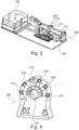
- FIG. 3 shows a structure for leak detection with an annular arrangement of a plurality of sensors 110, 310 and a displacement device and a control device 330.
- the displacement device comprises a movable component 370 and a stationary component 380.
- the movable component 370 here a movable slide, has a device in which a plurality of detectors are arranged in a ring shape.
- the annular assembly encloses a gas-filled tube having a surface 140 which is to be inspected for gas leaks 142.
- the gas tube has a cross-sectional area that has an axis of symmetry 390.
- the stationary component 380 has inter alia a stationary frame, in addition an evaluation device 120 and a control device 330. The latter controls the movement of the movable component 370 of the displacement device along the axis of symmetry 390 and thus the scanning process.
- FIG. 4 shows in detail the annular arrangement of the sensors 110, 310 FIG. 3 , which is part of the movable component 370 of the displacement device and encloses the surface 140 to be scanned, for example, of a gas pipe.
- the movable component 370 including the annular arrangement is movable along an axis of symmetry 390.
- the movable component has receiving devices for a sensor 110 and further sensors 310.
- the sensors 110, 310 are arranged along a closed line 491 which spans a two-dimensional shape which has the axis of symmetry 390 locally.
Landscapes
- Health & Medical Sciences (AREA)
- Physics & Mathematics (AREA)
- Life Sciences & Earth Sciences (AREA)
- Chemical & Material Sciences (AREA)
- General Physics & Mathematics (AREA)
- Immunology (AREA)
- Biochemistry (AREA)
- Analytical Chemistry (AREA)
- General Health & Medical Sciences (AREA)
- Pathology (AREA)
- Molecular Biology (AREA)
- Nuclear Medicine, Radiotherapy & Molecular Imaging (AREA)
- Chemical Kinetics & Catalysis (AREA)
- Biophysics (AREA)
- Dispersion Chemistry (AREA)
- Engineering & Computer Science (AREA)
- Plasma & Fusion (AREA)
- Optics & Photonics (AREA)
- Examining Or Testing Airtightness (AREA)
Applications Claiming Priority (1)
| Application Number | Priority Date | Filing Date | Title |
|---|---|---|---|
| ATA50316/2018A AT521072B1 (de) | 2018-04-12 | 2018-04-12 | Verfahren und Vorrichtung zur Detektion von Gaslecks |
Publications (2)
| Publication Number | Publication Date |
|---|---|
| EP3553488A1 true EP3553488A1 (fr) | 2019-10-16 |
| EP3553488B1 EP3553488B1 (fr) | 2021-03-24 |
Family
ID=66105225
Family Applications (1)
| Application Number | Title | Priority Date | Filing Date |
|---|---|---|---|
| EP19168709.4A Not-in-force EP3553488B1 (fr) | 2018-04-12 | 2019-04-11 | Procédé et dispositif de détection de fuites de gaz |
Country Status (2)
| Country | Link |
|---|---|
| EP (1) | EP3553488B1 (fr) |
| AT (1) | AT521072B1 (fr) |
Cited By (2)
| Publication number | Priority date | Publication date | Assignee | Title |
|---|---|---|---|---|
| CN113108992A (zh) * | 2021-03-05 | 2021-07-13 | 西安航天动力试验技术研究所 | 一种全量程肼类推进剂泄漏检测系统及方法 |
| WO2024033053A1 (fr) * | 2022-08-12 | 2024-02-15 | Lisa Dräxlmaier GmbH | Procédé et système de vérification de fuites dans un boîtier de batterie |
Citations (9)
| Publication number | Priority date | Publication date | Assignee | Title |
|---|---|---|---|---|
| DE819730C (de) * | 1950-07-07 | 1951-11-05 | Atlas Werke Ag | Verfahren und Vorrichtung zur Lecksuche |
| DE2717436A1 (de) * | 1976-04-26 | 1977-11-10 | Varian Associates | Verfahren und vorrichtung zur bestimmung des partialdruckes eines gases zur vakuummessung, leckanzeige, messung der niederschlagsrate o.dgl. |
| US5347845A (en) * | 1993-02-19 | 1994-09-20 | Whirlpool Corporation | Appliance shipping container air sampling system |
| WO1999010721A1 (fr) * | 1997-08-22 | 1999-03-04 | Caradon Stelrad Limited | Epreuve d'etancheite |
| DE10123079A1 (de) * | 2001-05-11 | 2002-11-21 | Draeger Medical Ag | Sauerstoffkonzentrationsmessung |
| WO2008068452A1 (fr) * | 2006-12-07 | 2008-06-12 | Cascade Technologies Limited | Système et procédé de détection de fuite |
| DE102015001443B3 (de) * | 2015-02-09 | 2016-05-25 | Schütz GmbH Meßtechnik | Gasspürgerät und Gasmessverfahren |
| DE102015219250A1 (de) * | 2015-10-06 | 2017-04-06 | Inficon Gmbh | Erfassung von Prüfgasschwankungen bei der Schnüffellecksuche |
| EP3184994A1 (fr) * | 2015-12-21 | 2017-06-28 | CSEM Centre Suisse d'Electronique et de Microtechnique SA - Recherche et Développement | Capteur optique pour détecter une espèce chimique, le système comprenant ce capteur et son procédé de fabrication |
Family Cites Families (5)
| Publication number | Priority date | Publication date | Assignee | Title |
|---|---|---|---|---|
| JPH06331609A (ja) * | 1993-05-20 | 1994-12-02 | Mitsubishi Electric Corp | 超音波探傷装置 |
| JP3101712B2 (ja) * | 1998-12-03 | 2000-10-23 | 東京工業大学長 | 匂い・ガス流可視化計測装置 |
| KR20020079248A (ko) * | 2001-04-14 | 2002-10-19 | 주식회사 대본전자산업 | 휴대용 가연성 가스누설감지기 |
| US20070030349A1 (en) * | 2005-01-31 | 2007-02-08 | Riley Larry E | Under vehicle inspection system |
| AT512675B1 (de) * | 2012-03-30 | 2015-12-15 | Joanneum Res Forschungsgmbh | Opto-chemischer Sensor |
-
2018
- 2018-04-12 AT ATA50316/2018A patent/AT521072B1/de not_active IP Right Cessation
-
2019
- 2019-04-11 EP EP19168709.4A patent/EP3553488B1/fr not_active Not-in-force
Patent Citations (9)
| Publication number | Priority date | Publication date | Assignee | Title |
|---|---|---|---|---|
| DE819730C (de) * | 1950-07-07 | 1951-11-05 | Atlas Werke Ag | Verfahren und Vorrichtung zur Lecksuche |
| DE2717436A1 (de) * | 1976-04-26 | 1977-11-10 | Varian Associates | Verfahren und vorrichtung zur bestimmung des partialdruckes eines gases zur vakuummessung, leckanzeige, messung der niederschlagsrate o.dgl. |
| US5347845A (en) * | 1993-02-19 | 1994-09-20 | Whirlpool Corporation | Appliance shipping container air sampling system |
| WO1999010721A1 (fr) * | 1997-08-22 | 1999-03-04 | Caradon Stelrad Limited | Epreuve d'etancheite |
| DE10123079A1 (de) * | 2001-05-11 | 2002-11-21 | Draeger Medical Ag | Sauerstoffkonzentrationsmessung |
| WO2008068452A1 (fr) * | 2006-12-07 | 2008-06-12 | Cascade Technologies Limited | Système et procédé de détection de fuite |
| DE102015001443B3 (de) * | 2015-02-09 | 2016-05-25 | Schütz GmbH Meßtechnik | Gasspürgerät und Gasmessverfahren |
| DE102015219250A1 (de) * | 2015-10-06 | 2017-04-06 | Inficon Gmbh | Erfassung von Prüfgasschwankungen bei der Schnüffellecksuche |
| EP3184994A1 (fr) * | 2015-12-21 | 2017-06-28 | CSEM Centre Suisse d'Electronique et de Microtechnique SA - Recherche et Développement | Capteur optique pour détecter une espèce chimique, le système comprenant ce capteur et son procédé de fabrication |
Cited By (3)
| Publication number | Priority date | Publication date | Assignee | Title |
|---|---|---|---|---|
| CN113108992A (zh) * | 2021-03-05 | 2021-07-13 | 西安航天动力试验技术研究所 | 一种全量程肼类推进剂泄漏检测系统及方法 |
| CN113108992B (zh) * | 2021-03-05 | 2023-10-20 | 西安航天动力试验技术研究所 | 一种全量程肼类推进剂泄漏检测系统及方法 |
| WO2024033053A1 (fr) * | 2022-08-12 | 2024-02-15 | Lisa Dräxlmaier GmbH | Procédé et système de vérification de fuites dans un boîtier de batterie |
Also Published As
| Publication number | Publication date |
|---|---|
| AT521072B1 (de) | 2020-01-15 |
| EP3553488B1 (fr) | 2021-03-24 |
| AT521072A1 (de) | 2019-10-15 |
Similar Documents
| Publication | Publication Date | Title |
|---|---|---|
| DE3712665A1 (de) | Teilchengroessendetektor mit hoher empfindlichkeit fuer umgebungen mit starker molekularstreuung | |
| DE19651101A1 (de) | Vorrichtung und Verfahren zur Detektion von fluoreszentem und phosphoreszentem Licht | |
| DE102011055272A1 (de) | Verfahren zur Bestimmung eines relaxationszeitabhängigen Parameters zu einem System | |
| EP3553488A1 (fr) | Procédé et dispositif de détection de fuites de gaz | |
| EP2936455B1 (fr) | Détecteur et procédé de vérification de documents de valeur | |
| DE102016007825A1 (de) | Verfahren und Vorrichtung zur Überwachung der Qualität von gasförmigen Medien | |
| EP1850119A1 (fr) | Capteur optique et procédé d'inspection optique de surfaces | |
| DE19617106A1 (de) | Fluoreszenzspektrometrische Meßsonde zur Bestimmung von organischen Fremdstoffen in Wasser und Böden | |
| DE10325537B4 (de) | Vorrichtung und Verfahren zum automatischen Detektieren von wenigstens einem in einem flüssigen Betriebsstoff enthaltenen fluoreszierenden und/oder lichtabsorbierenden Indikator während des Einfüllvorgangs des Betriebsstoffs in eine Maschine | |
| DE4007064A1 (de) | Vorrichtung zur bestimmung fluechtiger stoffe in einer fluessigkeit | |
| WO2010063806A1 (fr) | Dispositif et procédé permettant de déterminer une concentration d'oxygène | |
| DE1473380B2 (de) | Verfahren und Vorrichtung zum Untersuchen und/oder Messen von Spannungen in einem durchsichtigen Körper nach dem Streulichtverfahren | |
| DE102010041141B4 (de) | Sensor zur Überwachung eines Mediums | |
| DE102009008624B4 (de) | Anordnung zur Durchführung spektroskopischer Verfahren sowie Verwendung bei spektroskopischen Verfahren | |
| EP0624799A2 (fr) | Sonde de pression pour la détermination quantitative de polluants contenus dans l'eau souterraine | |
| DE3501093C1 (de) | Gasmess- und Warnvorrichtung | |
| EP0884409B1 (fr) | Dispositif pour la détection d'un étalon allongé | |
| WO2000020849A1 (fr) | Dispositif de detection de substances etrangeres dans un fil | |
| EP1436600B1 (fr) | Procédé de fabrication d'un capteur de gaz | |
| DE202016003193U1 (de) | Explosionsschutz | |
| AT507749A2 (de) | Verfahren und messanordnung zur bestimmung einer gelösten konzentration eines stoffes wie gasgehalts in einem fluid | |
| DE19631423B4 (de) | Verfahren zum ortsaufgelösten Substanznachweis | |
| DE4341016C2 (de) | Verfahren und Vorrichtung zur Überwachung von Deponieabdichtungssystemen | |
| DE19932354B4 (de) | Verfahren und Vorrichtung zum Fernnachweis von Kohlenwasserstoffen im untergrund- oder bodennahen Bereich der Atmosphäre | |
| DE29623263U1 (de) | Vorrichtung zum ortsaufgelösten Substanznachweis |
Legal Events
| Date | Code | Title | Description |
|---|---|---|---|
| PUAI | Public reference made under article 153(3) epc to a published international application that has entered the european phase |
Free format text: ORIGINAL CODE: 0009012 |
|
| STAA | Information on the status of an ep patent application or granted ep patent |
Free format text: STATUS: THE APPLICATION HAS BEEN PUBLISHED |
|
| AK | Designated contracting states |
Kind code of ref document: A1 Designated state(s): AL AT BE BG CH CY CZ DE DK EE ES FI FR GB GR HR HU IE IS IT LI LT LU LV MC MK MT NL NO PL PT RO RS SE SI SK SM TR |
|
| AX | Request for extension of the european patent |
Extension state: BA ME |
|
| STAA | Information on the status of an ep patent application or granted ep patent |
Free format text: STATUS: REQUEST FOR EXAMINATION WAS MADE |
|
| 17P | Request for examination filed |
Effective date: 20200325 |
|
| RBV | Designated contracting states (corrected) |
Designated state(s): AL AT BE BG CH CY CZ DE DK EE ES FI FR GB GR HR HU IE IS IT LI LT LU LV MC MK MT NL NO PL PT RO RS SE SI SK SM TR |
|
| GRAP | Despatch of communication of intention to grant a patent |
Free format text: ORIGINAL CODE: EPIDOSNIGR1 |
|
| STAA | Information on the status of an ep patent application or granted ep patent |
Free format text: STATUS: GRANT OF PATENT IS INTENDED |
|
| RIC1 | Information provided on ipc code assigned before grant |
Ipc: G01N 21/78 20060101ALI20200928BHEP Ipc: G01M 3/20 20060101AFI20200928BHEP Ipc: G01N 21/64 20060101ALI20200928BHEP |
|
| INTG | Intention to grant announced |
Effective date: 20201023 |
|
| GRAS | Grant fee paid |
Free format text: ORIGINAL CODE: EPIDOSNIGR3 |
|
| GRAA | (expected) grant |
Free format text: ORIGINAL CODE: 0009210 |
|
| STAA | Information on the status of an ep patent application or granted ep patent |
Free format text: STATUS: THE PATENT HAS BEEN GRANTED |
|
| AK | Designated contracting states |
Kind code of ref document: B1 Designated state(s): AL AT BE BG CH CY CZ DE DK EE ES FI FR GB GR HR HU IE IS IT LI LT LU LV MC MK MT NL NO PL PT RO RS SE SI SK SM TR |
|
| REG | Reference to a national code |
Ref country code: GB Ref legal event code: FG4D Free format text: NOT ENGLISH |
|
| REG | Reference to a national code |
Ref country code: CH Ref legal event code: EP |
|
| REG | Reference to a national code |
Ref country code: DE Ref legal event code: R096 Ref document number: 502019001035 Country of ref document: DE |
|
| REG | Reference to a national code |
Ref country code: IE Ref legal event code: FG4D Free format text: LANGUAGE OF EP DOCUMENT: GERMAN |
|
| REG | Reference to a national code |
Ref country code: AT Ref legal event code: REF Ref document number: 1374980 Country of ref document: AT Kind code of ref document: T Effective date: 20210415 |
|
| REG | Reference to a national code |
Ref country code: CH Ref legal event code: NV Representative=s name: RIEDERER HASLER AND PARTNER PATENTANWAELTE AG, LI |
|
| REG | Reference to a national code |
Ref country code: LT Ref legal event code: MG9D |
|
| PG25 | Lapsed in a contracting state [announced via postgrant information from national office to epo] |
Ref country code: NO Free format text: LAPSE BECAUSE OF FAILURE TO SUBMIT A TRANSLATION OF THE DESCRIPTION OR TO PAY THE FEE WITHIN THE PRESCRIBED TIME-LIMIT Effective date: 20210624 Ref country code: BG Free format text: LAPSE BECAUSE OF FAILURE TO SUBMIT A TRANSLATION OF THE DESCRIPTION OR TO PAY THE FEE WITHIN THE PRESCRIBED TIME-LIMIT Effective date: 20210624 Ref country code: GR Free format text: LAPSE BECAUSE OF FAILURE TO SUBMIT A TRANSLATION OF THE DESCRIPTION OR TO PAY THE FEE WITHIN THE PRESCRIBED TIME-LIMIT Effective date: 20210625 Ref country code: FI Free format text: LAPSE BECAUSE OF FAILURE TO SUBMIT A TRANSLATION OF THE DESCRIPTION OR TO PAY THE FEE WITHIN THE PRESCRIBED TIME-LIMIT Effective date: 20210324 Ref country code: HR Free format text: LAPSE BECAUSE OF FAILURE TO SUBMIT A TRANSLATION OF THE DESCRIPTION OR TO PAY THE FEE WITHIN THE PRESCRIBED TIME-LIMIT Effective date: 20210324 |
|
| PG25 | Lapsed in a contracting state [announced via postgrant information from national office to epo] |
Ref country code: RS Free format text: LAPSE BECAUSE OF FAILURE TO SUBMIT A TRANSLATION OF THE DESCRIPTION OR TO PAY THE FEE WITHIN THE PRESCRIBED TIME-LIMIT Effective date: 20210324 Ref country code: LV Free format text: LAPSE BECAUSE OF FAILURE TO SUBMIT A TRANSLATION OF THE DESCRIPTION OR TO PAY THE FEE WITHIN THE PRESCRIBED TIME-LIMIT Effective date: 20210324 Ref country code: SE Free format text: LAPSE BECAUSE OF FAILURE TO SUBMIT A TRANSLATION OF THE DESCRIPTION OR TO PAY THE FEE WITHIN THE PRESCRIBED TIME-LIMIT Effective date: 20210324 |
|
| REG | Reference to a national code |
Ref country code: NL Ref legal event code: MP Effective date: 20210324 |
|
| PG25 | Lapsed in a contracting state [announced via postgrant information from national office to epo] |
Ref country code: NL Free format text: LAPSE BECAUSE OF FAILURE TO SUBMIT A TRANSLATION OF THE DESCRIPTION OR TO PAY THE FEE WITHIN THE PRESCRIBED TIME-LIMIT Effective date: 20210324 |
|
| PG25 | Lapsed in a contracting state [announced via postgrant information from national office to epo] |
Ref country code: CZ Free format text: LAPSE BECAUSE OF FAILURE TO SUBMIT A TRANSLATION OF THE DESCRIPTION OR TO PAY THE FEE WITHIN THE PRESCRIBED TIME-LIMIT Effective date: 20210324 Ref country code: EE Free format text: LAPSE BECAUSE OF FAILURE TO SUBMIT A TRANSLATION OF THE DESCRIPTION OR TO PAY THE FEE WITHIN THE PRESCRIBED TIME-LIMIT Effective date: 20210324 Ref country code: LT Free format text: LAPSE BECAUSE OF FAILURE TO SUBMIT A TRANSLATION OF THE DESCRIPTION OR TO PAY THE FEE WITHIN THE PRESCRIBED TIME-LIMIT Effective date: 20210324 Ref country code: SM Free format text: LAPSE BECAUSE OF FAILURE TO SUBMIT A TRANSLATION OF THE DESCRIPTION OR TO PAY THE FEE WITHIN THE PRESCRIBED TIME-LIMIT Effective date: 20210324 |
|
| PG25 | Lapsed in a contracting state [announced via postgrant information from national office to epo] |
Ref country code: SK Free format text: LAPSE BECAUSE OF FAILURE TO SUBMIT A TRANSLATION OF THE DESCRIPTION OR TO PAY THE FEE WITHIN THE PRESCRIBED TIME-LIMIT Effective date: 20210324 Ref country code: RO Free format text: LAPSE BECAUSE OF FAILURE TO SUBMIT A TRANSLATION OF THE DESCRIPTION OR TO PAY THE FEE WITHIN THE PRESCRIBED TIME-LIMIT Effective date: 20210324 Ref country code: PT Free format text: LAPSE BECAUSE OF FAILURE TO SUBMIT A TRANSLATION OF THE DESCRIPTION OR TO PAY THE FEE WITHIN THE PRESCRIBED TIME-LIMIT Effective date: 20210726 Ref country code: PL Free format text: LAPSE BECAUSE OF FAILURE TO SUBMIT A TRANSLATION OF THE DESCRIPTION OR TO PAY THE FEE WITHIN THE PRESCRIBED TIME-LIMIT Effective date: 20210324 Ref country code: IS Free format text: LAPSE BECAUSE OF FAILURE TO SUBMIT A TRANSLATION OF THE DESCRIPTION OR TO PAY THE FEE WITHIN THE PRESCRIBED TIME-LIMIT Effective date: 20210724 |
|
| PG25 | Lapsed in a contracting state [announced via postgrant information from national office to epo] |
Ref country code: LU Free format text: LAPSE BECAUSE OF NON-PAYMENT OF DUE FEES Effective date: 20210411 |
|
| REG | Reference to a national code |
Ref country code: DE Ref legal event code: R097 Ref document number: 502019001035 Country of ref document: DE |
|
| REG | Reference to a national code |
Ref country code: BE Ref legal event code: MM Effective date: 20210430 |
|
| PG25 | Lapsed in a contracting state [announced via postgrant information from national office to epo] |
Ref country code: ES Free format text: LAPSE BECAUSE OF FAILURE TO SUBMIT A TRANSLATION OF THE DESCRIPTION OR TO PAY THE FEE WITHIN THE PRESCRIBED TIME-LIMIT Effective date: 20210324 Ref country code: AL Free format text: LAPSE BECAUSE OF FAILURE TO SUBMIT A TRANSLATION OF THE DESCRIPTION OR TO PAY THE FEE WITHIN THE PRESCRIBED TIME-LIMIT Effective date: 20210324 Ref country code: DK Free format text: LAPSE BECAUSE OF FAILURE TO SUBMIT A TRANSLATION OF THE DESCRIPTION OR TO PAY THE FEE WITHIN THE PRESCRIBED TIME-LIMIT Effective date: 20210324 Ref country code: MC Free format text: LAPSE BECAUSE OF FAILURE TO SUBMIT A TRANSLATION OF THE DESCRIPTION OR TO PAY THE FEE WITHIN THE PRESCRIBED TIME-LIMIT Effective date: 20210324 |
|
| PLBE | No opposition filed within time limit |
Free format text: ORIGINAL CODE: 0009261 |
|
| STAA | Information on the status of an ep patent application or granted ep patent |
Free format text: STATUS: NO OPPOSITION FILED WITHIN TIME LIMIT |
|
| PG25 | Lapsed in a contracting state [announced via postgrant information from national office to epo] |
Ref country code: SI Free format text: LAPSE BECAUSE OF FAILURE TO SUBMIT A TRANSLATION OF THE DESCRIPTION OR TO PAY THE FEE WITHIN THE PRESCRIBED TIME-LIMIT Effective date: 20210324 |
|
| 26N | No opposition filed |
Effective date: 20220104 |
|
| PG25 | Lapsed in a contracting state [announced via postgrant information from national office to epo] |
Ref country code: IE Free format text: LAPSE BECAUSE OF NON-PAYMENT OF DUE FEES Effective date: 20210411 |
|
| PG25 | Lapsed in a contracting state [announced via postgrant information from national office to epo] |
Ref country code: IS Free format text: LAPSE BECAUSE OF FAILURE TO SUBMIT A TRANSLATION OF THE DESCRIPTION OR TO PAY THE FEE WITHIN THE PRESCRIBED TIME-LIMIT Effective date: 20210724 |
|
| PG25 | Lapsed in a contracting state [announced via postgrant information from national office to epo] |
Ref country code: BE Free format text: LAPSE BECAUSE OF NON-PAYMENT OF DUE FEES Effective date: 20210430 |
|
| PGFP | Annual fee paid to national office [announced via postgrant information from national office to epo] |
Ref country code: DE Payment date: 20220422 Year of fee payment: 4 |
|
| PGFP | Annual fee paid to national office [announced via postgrant information from national office to epo] |
Ref country code: CH Payment date: 20220429 Year of fee payment: 4 |
|
| PG25 | Lapsed in a contracting state [announced via postgrant information from national office to epo] |
Ref country code: IT Free format text: LAPSE BECAUSE OF FAILURE TO SUBMIT A TRANSLATION OF THE DESCRIPTION OR TO PAY THE FEE WITHIN THE PRESCRIBED TIME-LIMIT Effective date: 20210324 |
|
| PG25 | Lapsed in a contracting state [announced via postgrant information from national office to epo] |
Ref country code: CY Free format text: LAPSE BECAUSE OF FAILURE TO SUBMIT A TRANSLATION OF THE DESCRIPTION OR TO PAY THE FEE WITHIN THE PRESCRIBED TIME-LIMIT Effective date: 20210324 |
|
| PG25 | Lapsed in a contracting state [announced via postgrant information from national office to epo] |
Ref country code: HU Free format text: LAPSE BECAUSE OF FAILURE TO SUBMIT A TRANSLATION OF THE DESCRIPTION OR TO PAY THE FEE WITHIN THE PRESCRIBED TIME-LIMIT; INVALID AB INITIO Effective date: 20190411 |
|
| PGFP | Annual fee paid to national office [announced via postgrant information from national office to epo] |
Ref country code: FR Payment date: 20230426 Year of fee payment: 5 |
|
| REG | Reference to a national code |
Ref country code: DE Ref legal event code: R119 Ref document number: 502019001035 Country of ref document: DE |
|
| REG | Reference to a national code |
Ref country code: CH Ref legal event code: PL |
|
| GBPC | Gb: european patent ceased through non-payment of renewal fee |
Effective date: 20230411 |
|
| PG25 | Lapsed in a contracting state [announced via postgrant information from national office to epo] |
Ref country code: GB Free format text: LAPSE BECAUSE OF NON-PAYMENT OF DUE FEES Effective date: 20230411 |
|
| PG25 | Lapsed in a contracting state [announced via postgrant information from national office to epo] |
Ref country code: LI Free format text: LAPSE BECAUSE OF NON-PAYMENT OF DUE FEES Effective date: 20230430 Ref country code: GB Free format text: LAPSE BECAUSE OF NON-PAYMENT OF DUE FEES Effective date: 20230411 Ref country code: DE Free format text: LAPSE BECAUSE OF NON-PAYMENT OF DUE FEES Effective date: 20231103 Ref country code: CH Free format text: LAPSE BECAUSE OF NON-PAYMENT OF DUE FEES Effective date: 20230430 |
|
| PG25 | Lapsed in a contracting state [announced via postgrant information from national office to epo] |
Ref country code: MK Free format text: LAPSE BECAUSE OF FAILURE TO SUBMIT A TRANSLATION OF THE DESCRIPTION OR TO PAY THE FEE WITHIN THE PRESCRIBED TIME-LIMIT Effective date: 20210324 |
|
| PG25 | Lapsed in a contracting state [announced via postgrant information from national office to epo] |
Ref country code: MT Free format text: LAPSE BECAUSE OF FAILURE TO SUBMIT A TRANSLATION OF THE DESCRIPTION OR TO PAY THE FEE WITHIN THE PRESCRIBED TIME-LIMIT Effective date: 20210324 |
|
| PG25 | Lapsed in a contracting state [announced via postgrant information from national office to epo] |
Ref country code: FR Free format text: LAPSE BECAUSE OF NON-PAYMENT OF DUE FEES Effective date: 20240430 |
|
| PG25 | Lapsed in a contracting state [announced via postgrant information from national office to epo] |
Ref country code: FR Free format text: LAPSE BECAUSE OF NON-PAYMENT OF DUE FEES Effective date: 20240430 |
|
| REG | Reference to a national code |
Ref country code: AT Ref legal event code: MM01 Ref document number: 1374980 Country of ref document: AT Kind code of ref document: T Effective date: 20240411 |
|
| PG25 | Lapsed in a contracting state [announced via postgrant information from national office to epo] |
Ref country code: AT Free format text: LAPSE BECAUSE OF NON-PAYMENT OF DUE FEES Effective date: 20240411 |
|
| PG25 | Lapsed in a contracting state [announced via postgrant information from national office to epo] |
Ref country code: TR Free format text: LAPSE BECAUSE OF FAILURE TO SUBMIT A TRANSLATION OF THE DESCRIPTION OR TO PAY THE FEE WITHIN THE PRESCRIBED TIME-LIMIT Effective date: 20210324 |
|
| PGFP | Annual fee paid to national office [announced via postgrant information from national office to epo] |
Ref country code: AT Payment date: 20260410 Year of fee payment: 5 |