EP3553533A1 - Sonde de couche limite, dispositif de mesure ainsi que procédé de détermination d'un flux d'un fluide - Google Patents
Sonde de couche limite, dispositif de mesure ainsi que procédé de détermination d'un flux d'un fluide Download PDFInfo
- Publication number
- EP3553533A1 EP3553533A1 EP18167059.7A EP18167059A EP3553533A1 EP 3553533 A1 EP3553533 A1 EP 3553533A1 EP 18167059 A EP18167059 A EP 18167059A EP 3553533 A1 EP3553533 A1 EP 3553533A1
- Authority
- EP
- European Patent Office
- Prior art keywords
- boundary layer
- measuring
- obstacles
- pressure
- layer probe
- Prior art date
- Legal status (The legal status is an assumption and is not a legal conclusion. Google has not performed a legal analysis and makes no representation as to the accuracy of the status listed.)
- Granted
Links
Images

Classifications
-
- G—PHYSICS
- G01—MEASURING; TESTING
- G01P—MEASURING LINEAR OR ANGULAR SPEED, ACCELERATION, DECELERATION, OR SHOCK; INDICATING PRESENCE, ABSENCE, OR DIRECTION, OF MOVEMENT
- G01P5/00—Measuring speed of fluids, e.g. of air stream; Measuring speed of bodies relative to fluids, e.g. of ship, of aircraft
- G01P5/14—Measuring speed of fluids, e.g. of air stream; Measuring speed of bodies relative to fluids, e.g. of ship, of aircraft by measuring differences of pressure in the fluid
-
- G—PHYSICS
- G01—MEASURING; TESTING
- G01F—MEASURING VOLUME, VOLUME FLOW, MASS FLOW OR LIQUID LEVEL; METERING BY VOLUME
- G01F1/00—Measuring the volume flow or mass flow of fluid or fluent solid material wherein the fluid passes through a meter in a continuous flow
- G01F1/05—Measuring the volume flow or mass flow of fluid or fluent solid material wherein the fluid passes through a meter in a continuous flow by using mechanical effects
- G01F1/20—Measuring the volume flow or mass flow of fluid or fluent solid material wherein the fluid passes through a meter in a continuous flow by using mechanical effects by detection of dynamic effects of the flow
- G01F1/206—Measuring pressure, force or momentum of a fluid flow which is forced to change its direction
-
- G—PHYSICS
- G01—MEASURING; TESTING
- G01F—MEASURING VOLUME, VOLUME FLOW, MASS FLOW OR LIQUID LEVEL; METERING BY VOLUME
- G01F1/00—Measuring the volume flow or mass flow of fluid or fluent solid material wherein the fluid passes through a meter in a continuous flow
- G01F1/05—Measuring the volume flow or mass flow of fluid or fluent solid material wherein the fluid passes through a meter in a continuous flow by using mechanical effects
- G01F1/34—Measuring the volume flow or mass flow of fluid or fluent solid material wherein the fluid passes through a meter in a continuous flow by using mechanical effects by measuring pressure or differential pressure
- G01F1/36—Measuring the volume flow or mass flow of fluid or fluent solid material wherein the fluid passes through a meter in a continuous flow by using mechanical effects by measuring pressure or differential pressure the pressure or differential pressure being created by the use of flow constriction
-
- G—PHYSICS
- G01—MEASURING; TESTING
- G01M—TESTING STATIC OR DYNAMIC BALANCE OF MACHINES OR STRUCTURES; TESTING OF STRUCTURES OR APPARATUS, NOT OTHERWISE PROVIDED FOR
- G01M9/00—Aerodynamic testing; Arrangements in or on wind tunnels
- G01M9/06—Measuring arrangements specially adapted for aerodynamic testing
Definitions
- the invention relates to a boundary layer probe, a measuring arrangement and a method for determining a fluid flow.
- the so-called surface fence probe represents in its simplest form with a single straight fence (obstacle) a proven and widely used measurement technique for the determination of wall shear stresses and near-wall flow velocities.
- the measuring principle is to disturb the flow of fluid near the wall through a microscopic obstacle (in this case a fence).
- boundary layer probes are located in front of and behind the fence pressure holes, which can be summarized as differential pressure. If the fence is overflowed, upstream creates a Aufstau- and downstream of a detachment area, or an overpressure and underpressure. A rotation of the probe through 360 ° provides the so-called angle characteristic - a differential pressure curve in cosine form.
- both the angle of the inflow and the absolute speed value can be determined.
- the probe must be completely turned once around itself. This fact has many disadvantages. On the one hand, this eliminates the possibility instantaneous fluctuations of the fluid movement to measure and on the other hand, the measurement structure is due to its complexity for many practical applications unsuitable. In addition, the measurement effort must be classified as relatively high, since the probe must be rotated in equidistant steps by 360 °.
- the surface fence probe is also referred to as a boundary layer probe.
- the wall shear stress is the tangentially acting force per unit area exerted by a fluid on walls that are flown around and, by definition, has a direction.
- the wall shear stress is the momentum flux through the volume of fluid adjacent to the wall and follows from the friction of the fluid elements on the wall and with each other.
- both the directional vectorial shape and its magnitude are called wall shear stress.
- the object of the invention is to provide a boundary layer probe, a measuring arrangement and a method for determining a fluid flow, with which the flow properties in the near-wall region (boundary layer) can be determined in an improved manner.
- a boundary layer probe for determining a fluid flow has a measuring surface which is formed on a probe wall and along which a fluid flow to be determined is applied during measurement operation.
- An arrangement of measuring obstacles is provided, which are formed in the region of the measuring surface, which disturb the fluid flow in a flow region adjacent to the measuring surface.
- the measurement obstacles each have an elongated obstacle course, which extends over a respective obstacle length.
- the measurement obstacles are arranged in the circumferential direction at substantially equidistant angular distances.
- the boundary layer probe has pressure measuring points, which are arranged adjacent to an associated one of the obstacles for detecting a respective local pressure in the region of the measuring surface in each case in the radial direction.
- a measuring arrangement for determining a fluid flow with the boundary layer probe has a measuring space which is set up to receive a flow of a fluid flow to be determined, wherein the flow can flow along a probe wall of the boundary layer probe with a measuring surface formed thereon.
- a pressure measuring device is provided, which is set up to detect a local pressure at pressure measuring points in the area of the measuring surface of the boundary layer probe.
- a method for determining a wall shear stress for a fluid flow wherein a boundary layer probe is provided and a flow of a fluid flow to be determined is formed in a measurement space.
- the Flow here flows along a probe wall of the boundary layer probe with a measuring surface formed thereon.
- Pressure readings for a local pressure at pressure measuring points in the area of the measuring surface of the boundary layer probe are recorded, whereby differential pressures are detected for adjacent pressure measuring points.
- at least one physical measured variable for a boundary layer of the fluid flow on the measurement surface of the boundary layer probe is determined, wherein the at least one physical measured variable is selected from the following group: flow velocity and wall shear stress.
- determining the fluid flow may be provided to determine a direction of the fluid flow.
- the measurement obstacles arranged in the circumferential direction at essentially equidistant angular distances form an efficient arrangement of measurement obstacles in order to determine physical measured variables for the boundary layer of the fluid flow on the measurement surface, for example the wall shear stress, in particular with respect to magnitude and / or direction.
- the measurement obstacles form an arrangement of microscopic obstacles which interfere with the fluid flow to be determined in its boundary layer region (wall-near region to the measurement surface of the boundary layer probe) when it flows along the measurement surface on the probe wall. This results in characteristic pressure conditions in the region of the measuring surface, which are measured by means of the pressure measuring points, in order to determine one or more physical measuring or characteristic quantities for the fluid flow in the near-wall region.
- the measuring surface may be formed with different surface peripheral shapes, for example a round or angular shape.
- the boundary layer probe may be integrated with a wall of a flow channel or tube through which the fluid stream flows.
- the measuring surface may be formed by a wall portion of the wall.
- the obstacles of the arrangement of measuring obstacles can all be the same or different, in particular with regard to their elongated obstacle course and / or obstacle height or depth.
- the physical measured variable can be determined, in particular the wall shear stress, as is known per se in connection with a boundary layer probe.
- the obstacles can be arranged rotationally symmetrical in the area of the measuring surface. This means that the obstacles can be brought to coincide with each other by rotating the measuring surface around a center of the arrangement of measuring obstacles.
- the elongated obstacle course may extend at least in sections along a curved line.
- the elongated obstacles may be rectilinear. It may be a combination of one or more curved or curved sections and one or more straight sections provided in the elongated obstacle course.
- a central portion of the elongated obstacle course for the obstacles is curved or arched.
- the middle section is followed on both sides by radially outwardly directed rectilinear sections of the obstacle course.
- the elongated obstacle course can be formed for the obstacles in each case continuously or intermittently.
- the elongated obstacle course may be concave or convexly curved with respect to a center or center of the array of measurement obstacles.
- the elongate obstacle course with respect to the center of the array of measurement obstacles may be curved away therefrom.
- a radius of curvature in the curved portion of the elongated obstacle course may be the same for all obstacles of the assembly. Alternatively, different radii of curvature may be provided.
- Distal end sections of adjacent measurement obstacles can be arranged adjacent to one another on one or both sides adjacent to one another.
- the distal end sections that is to say the sections of the elongated obstacle courses which are arranged radially on the outside, can terminate at the peripheral outer edge of the measuring surface.
- the end of the distal end portion is radially inwardly spaced from the outer edge.
- the adjacent arrangement of the distal end portions may be parallel or wedge-shaped. The adjacent trace may abut the outer edge of the measurement surface or terminate at a distance therefrom.
- the distal end portions of the adjacent measurement obstacles may be interconnected.
- a closed course of the obstacles may be formed, be it in a circle, star or polygonal shape.
- the pressure measuring points can each be arranged in a central portion of the associated obstacle.
- a pressure measuring point assigned to the respective obstacle can be arranged in the middle of the elongated course of the obstacle.
- the obstacles may each be formed with at least one obstacle shape from the following group: on the measuring surface protruding web or fence and arranged on the measuring surface recess, for example in the form of a trench.
- the obstacle shapes can be designed to be continuous or interrupted for the obstacles.
- the arrangement of measurement obstacles may have at least three obstacles.
- the number of pressure measuring openings can be equal to the number of obstacles.
- the at least three obstacles may be implemented separately or connected to each other.
- a closed obstacle course may be formed, in which the obstacles each at least one pressure measuring point is assigned.
- the pressure measuring points can be designed with a respective pressure measuring opening, which can open into an associated channel section at the rear, which has a connection for the pressure measuring device.
- the channel section can extend transversely thereto on the rear side of the measuring surface.
- a channel cross section can change.
- a channel section directly adjoining the pressure measuring opening may be formed with a first channel cross section, whereas a channel section adjoining thereon at the rear has a second channel cross section which is larger than the first channel cross section.
- a connection for the pressure measuring device can be arranged at a distal end of the channel section.
- one or more of the pressure measuring points may be formed with a pressure measuring device arranged on the measuring surface, for example a pressure-sensitive measuring foil, which may optionally be at least partially embedded in an associated opening or arranged on the measuring plane.
- a pressure measuring device arranged on the measuring surface, for example a pressure-sensitive measuring foil, which may optionally be at least partially embedded in an associated opening or arranged on the measuring plane.
- Each of the measuring obstacles can be assigned to exactly one pressure measuring point. Alternatively, more than one pressure measuring point may be associated with one or more of the measuring obstacles.
- the embodiments explained above for the boundary layer probe can be provided accordingly.
- the pressure measured values can be detected time-resolved, from which physical measured variable can be determined in magnitude and / or direction, for example the wall shear stress and / or a Feache founded in the boundary layer region of the fluid flow on the measuring surface.
- the direction of the physical measured variable, in particular the direction of the wall shear stress, of the fluid flow can be determined freely from a rotation of the measuring surface with the measuring obstacles.
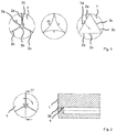
- Fig. 1 shows a schematic representation of a measuring surface 1 of a boundary layer probe for determining a fluid flow, in particular the direction of the fluid flow, with different arrangements a), b) and c) of measurement obstacles 2a, 2b, 2c, as projecting forward microscopic ridges or in the measuring surface 1 recessed depressions are formed, such that a fluid flow to be determined, which flows past the measuring surface 1 locally by the measuring obstacles 2a, 2b, 2c is disturbed, so that local pressure conditions set, then in pressure measuring points 3a, 3b, 3c, which, respectively one of the measurement obstacles 2a, 2b, 2c are assigned, can be tapped.
- a respective pressure measuring device may be arranged on the measuring surface 1, for example in the form of a pressure-sensitive film in order to measure the local pressure.
- Fig. 2 shows in this context a schematic representation of the arrangement a) of measuring obstacles 2a, 2b, 2c, wherein on the right side a sectional view is shown, in which behind the pressure measuring port a channel 4 with a first and a second channel section 4a, 4b is shown, which extends transversely to the measuring surface 1 at the back of the pressure measuring opening.
- a pressure measuring device (not shown) can be connected to measure the pressure.
- Fig. 3 shows further embodiments of a boundary layer probe, in which on the measuring surface 1, an array of measuring obstacles 2a, 2b, 2c is arranged.
- distal end sections 6a, 6b of adjacent measurement obstacles are connected to one another, so that a continuous profile is produced.
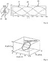
- the 4 and 5 show differential pressure curves and a 4D calibration curve.
- Fig. 4 shows results of measurements. Analogous to the known boundary layer probe with boundary layer fence, the differential pressure profiles are used as a basis for evaluation. Each two pressures are summarized here in the form of a differential pressure to a measured value.
- ⁇ str O ⁇ mung f ⁇ p 1 - 2 . ⁇ p 2 - 3 . p ⁇ 3 - 1
- An alternative evaluation algorithm is based on a linearization of the above-mentioned angle characteristic. For linear interpolation at least two differential pressures are necessary. In the present case, there are three. In the simplest case, a boundary layer probe with n webs would provide n differential pressure values and further improve the angle determination.
Landscapes
- Physics & Mathematics (AREA)
- General Physics & Mathematics (AREA)
- Fluid Mechanics (AREA)
- Engineering & Computer Science (AREA)
- Aviation & Aerospace Engineering (AREA)
- Measuring Fluid Pressure (AREA)
- Measuring Volume Flow (AREA)
- Indicating Or Recording The Presence, Absence, Or Direction Of Movement (AREA)
Priority Applications (3)
| Application Number | Priority Date | Filing Date | Title |
|---|---|---|---|
| EP18167059.7A EP3553533B1 (fr) | 2018-04-12 | 2018-04-12 | Sonde de couche limite, dispositif de mesure ainsi que procédé de détermination d'un flux d'un fluide |
| US17/046,008 US12061211B2 (en) | 2018-04-12 | 2019-04-12 | Boundary layer probe, measuring assembly, and method for determining a fluid flow |
| PCT/EP2019/059433 WO2019197614A1 (fr) | 2018-04-12 | 2019-04-12 | Sonde d'interface, agencement de mesure et procédé destiné à déterminer un courant de fluide |
Applications Claiming Priority (1)
| Application Number | Priority Date | Filing Date | Title |
|---|---|---|---|
| EP18167059.7A EP3553533B1 (fr) | 2018-04-12 | 2018-04-12 | Sonde de couche limite, dispositif de mesure ainsi que procédé de détermination d'un flux d'un fluide |
Publications (2)
| Publication Number | Publication Date |
|---|---|
| EP3553533A1 true EP3553533A1 (fr) | 2019-10-16 |
| EP3553533B1 EP3553533B1 (fr) | 2021-09-29 |
Family
ID=61972374
Family Applications (1)
| Application Number | Title | Priority Date | Filing Date |
|---|---|---|---|
| EP18167059.7A Active EP3553533B1 (fr) | 2018-04-12 | 2018-04-12 | Sonde de couche limite, dispositif de mesure ainsi que procédé de détermination d'un flux d'un fluide |
Country Status (3)
| Country | Link |
|---|---|
| US (1) | US12061211B2 (fr) |
| EP (1) | EP3553533B1 (fr) |
| WO (1) | WO2019197614A1 (fr) |
Cited By (2)
| Publication number | Priority date | Publication date | Assignee | Title |
|---|---|---|---|---|
| CN112067246A (zh) * | 2020-09-21 | 2020-12-11 | 中国空气动力研究与发展中心高速空气动力研究所 | 一种非对称圆弧形边界层测压排架 |
| CN114608792A (zh) * | 2022-05-10 | 2022-06-10 | 中国空气动力研究与发展中心高速空气动力研究所 | 短轴探管测量高速射流风洞亚跨声速射流流场均匀区方法 |
Families Citing this family (1)
| Publication number | Priority date | Publication date | Assignee | Title |
|---|---|---|---|---|
| CN115356074B (zh) * | 2022-08-11 | 2024-06-18 | 中国人民解放军国防科技大学 | 一种高空间分辨率移动式皮托压力测量耙及其制备方法 |
Citations (3)
| Publication number | Priority date | Publication date | Assignee | Title |
|---|---|---|---|---|
| WO1993015388A1 (fr) * | 1991-01-31 | 1993-08-05 | Rolls-Royce Plc | Transducteur de contrainte de cisaillement d'un fluide |
| DE19724116A1 (de) * | 1997-06-09 | 1998-12-10 | Klaus Prof Dr Ing Gersten | Verfahren und Vorrichtung zur Korrektur fehlerhafter Meßwerte von Durchflußmeßgeräten infolge gestörter Zuströmung |
| EP1314985A1 (fr) * | 2001-11-21 | 2003-05-28 | EADS Deutschland GmbH | Dispositif de mesure de données aérodynamiques et système de mesure de données aérodynamiques pour des aéronefs |
Family Cites Families (9)
| Publication number | Priority date | Publication date | Assignee | Title |
|---|---|---|---|---|
| US3832903A (en) * | 1972-09-07 | 1974-09-03 | Nasa | Stagnation pressure probe |
| DE19957956A1 (de) * | 1999-12-02 | 2001-06-07 | Ruhrgas Ag | Verfahren und Vorrichtung zur Durchflußmessung von Gasen und Flüssigkeiten |
| GB2383136B (en) * | 2001-12-14 | 2004-01-14 | Schlumberger Holdings | Flow characteristic measuring apparatus and method |
| GB2491167A (en) * | 2011-05-26 | 2012-11-28 | Bae Systems Plc | Aircraft wing blister |
| GB2496526A (en) * | 2011-11-14 | 2013-05-15 | Paradigm Flow Services Ltd | Condition monitoring of fluid conduits |
| US9528865B2 (en) * | 2012-11-02 | 2016-12-27 | Johnson Controls Technology Company | Methods and systems for determining flow direction using a bidirectional pressure sensor |
| FR3007527B1 (fr) * | 2013-06-19 | 2019-05-31 | Polyvionics | Dispositif de mesure de la vitesse de deplacement d'un fluide par rapport a un objet. |
| US20160334253A1 (en) * | 2014-01-28 | 2016-11-17 | Polyvionics | Device for measuring the travelling speed of a fluid in relation to an object |
| FR3024665B1 (fr) * | 2014-08-11 | 2020-05-08 | Technologies Avancees Et Membranes Industrielles | Element de separation par flux tangentiel integrant des obstacles a la circulation et procede de fabrication |
-
2018
- 2018-04-12 EP EP18167059.7A patent/EP3553533B1/fr active Active
-
2019
- 2019-04-12 WO PCT/EP2019/059433 patent/WO2019197614A1/fr not_active Ceased
- 2019-04-12 US US17/046,008 patent/US12061211B2/en active Active
Patent Citations (3)
| Publication number | Priority date | Publication date | Assignee | Title |
|---|---|---|---|---|
| WO1993015388A1 (fr) * | 1991-01-31 | 1993-08-05 | Rolls-Royce Plc | Transducteur de contrainte de cisaillement d'un fluide |
| DE19724116A1 (de) * | 1997-06-09 | 1998-12-10 | Klaus Prof Dr Ing Gersten | Verfahren und Vorrichtung zur Korrektur fehlerhafter Meßwerte von Durchflußmeßgeräten infolge gestörter Zuströmung |
| EP1314985A1 (fr) * | 2001-11-21 | 2003-05-28 | EADS Deutschland GmbH | Dispositif de mesure de données aérodynamiques et système de mesure de données aérodynamiques pour des aéronefs |
Non-Patent Citations (1)
| Title |
|---|
| CHENGYU MA ET AL: "A study of directional MEMS dual-fences gauge", 10TH IEEE INTERNATIONAL CONFERENCE ON NANO/MICRO ENGINEERED AND MOLECULAR SYSTEMS, IEEE, 7 April 2015 (2015-04-07), pages 449 - 452, XP033170209, DOI: 10.1109/NEMS.2015.7147465 * |
Cited By (3)
| Publication number | Priority date | Publication date | Assignee | Title |
|---|---|---|---|---|
| CN112067246A (zh) * | 2020-09-21 | 2020-12-11 | 中国空气动力研究与发展中心高速空气动力研究所 | 一种非对称圆弧形边界层测压排架 |
| CN114608792A (zh) * | 2022-05-10 | 2022-06-10 | 中国空气动力研究与发展中心高速空气动力研究所 | 短轴探管测量高速射流风洞亚跨声速射流流场均匀区方法 |
| CN114608792B (zh) * | 2022-05-10 | 2022-07-15 | 中国空气动力研究与发展中心高速空气动力研究所 | 短轴探管测量高速射流风洞亚跨声速射流流场均匀区方法 |
Also Published As
| Publication number | Publication date |
|---|---|
| US20210072013A1 (en) | 2021-03-11 |
| US12061211B2 (en) | 2024-08-13 |
| EP3553533B1 (fr) | 2021-09-29 |
| WO2019197614A1 (fr) | 2019-10-17 |
Similar Documents
| Publication | Publication Date | Title |
|---|---|---|
| EP0046965B1 (fr) | Procédé et appareil pour la détermination dynamique du débit massique independant de la densité | |
| DE2640087C2 (fr) | ||
| EP2406585B1 (fr) | Procédé et appareil de mesure d'écoulement tourbillonnaire, destinés à surveiller et/ou mesurer un écoulement pariétal d'un fluide traversant une conduite tubulaire et possédant deux phases ou plus | |
| DE2512644A1 (de) | Vorrichtung zur messung des durchflusses und/oder viskositaet von fluiden | |
| DE2204269B2 (de) | Länglicher Wirbelkörper zum Messen der Strömungsgeschwindigkeit eines Strömungsmittels in einer Leitung | |
| EP2636990B1 (fr) | Corps de mesure pour un dispositif de mesure pneumatique | |
| EP3553533B1 (fr) | Sonde de couche limite, dispositif de mesure ainsi que procédé de détermination d'un flux d'un fluide | |
| WO2017012811A1 (fr) | Débitmètre à effet vortex | |
| EP2041523B1 (fr) | Dispositif de mesure servant à la mesure du débit dans un canal | |
| DE102010012924A1 (de) | Massenstromsensor und Verfahren zur Bestimmung des Massenstroms in einem Rohr | |
| CH708523A2 (de) | System und Verfahren zur Überwachung einer rotierenden Komponente. | |
| EP2554964B1 (fr) | Dispositif de mesure de la pression et de la température | |
| DE3140663A1 (de) | "duesenpitot-messfuehler" | |
| DE102006043283A1 (de) | Messanordnung zur Erfassung eines 1/Umdrehungsimpulses eines Triebwerkrotors sowie Verfahren hierzu | |
| DE10303876A1 (de) | Messanordnung, Wälzlager und Verfahren zur Ermittlung der Bewegungsrichtung eines Wälzlagerbauteils | |
| EP3514505B1 (fr) | Débitmètre | |
| DE102005053335B4 (de) | Verfahren zur Messung des Verschleißes an den Laufflächen von Dichtungslaufringen und Verschleißmeßvorrichtung zur Durchführung des Verfahrens | |
| EP3748308A1 (fr) | Débitmètre à ultrasons, utilisation d'un débitmètre à ultrasons dans un organe d'arrêt et organe d'arrêt | |
| DE102007023163B4 (de) | Durchflussmesser | |
| EP2933610B1 (fr) | Débitmètre de turbine à large plage de fonctionnement et détermination précise de débit | |
| WO2015165782A2 (fr) | Capteur et procédé pour capter au moins une grandeur de mesure mesurable d'un agent dans un tube | |
| DE102014013212A1 (de) | Flussmesser für Fluide und Gase mit großem dynamischen Messbereich | |
| DE102014205040A1 (de) | Durchflussmesser und Verfahren für einen Durchflussmesser | |
| EP3748309A1 (fr) | Débitmètre à ultrasons, utilisation d'un débitmètre à ultrasons dans un organe d'arrêt et organe d'arrêt | |
| DE2757384A1 (de) | Nach dem prinzip der wirbelabloesung arbeitender durchflussmesser |
Legal Events
| Date | Code | Title | Description |
|---|---|---|---|
| PUAI | Public reference made under article 153(3) epc to a published international application that has entered the european phase |
Free format text: ORIGINAL CODE: 0009012 |
|
| STAA | Information on the status of an ep patent application or granted ep patent |
Free format text: STATUS: THE APPLICATION HAS BEEN PUBLISHED |
|
| AK | Designated contracting states |
Kind code of ref document: A1 Designated state(s): AL AT BE BG CH CY CZ DE DK EE ES FI FR GB GR HR HU IE IS IT LI LT LU LV MC MK MT NL NO PL PT RO RS SE SI SK SM TR |
|
| AX | Request for extension of the european patent |
Extension state: BA ME |
|
| STAA | Information on the status of an ep patent application or granted ep patent |
Free format text: STATUS: REQUEST FOR EXAMINATION WAS MADE |
|
| 17P | Request for examination filed |
Effective date: 20200415 |
|
| RBV | Designated contracting states (corrected) |
Designated state(s): AL AT BE BG CH CY CZ DE DK EE ES FI FR GB GR HR HU IE IS IT LI LT LU LV MC MK MT NL NO PL PT RO RS SE SI SK SM TR |
|
| STAA | Information on the status of an ep patent application or granted ep patent |
Free format text: STATUS: EXAMINATION IS IN PROGRESS |
|
| 17Q | First examination report despatched |
Effective date: 20201027 |
|
| RIN1 | Information on inventor provided before grant (corrected) |
Inventor name: RUECKERT, ROLAND Inventor name: WIESER, DIRK Inventor name: ECK, MARIO Inventor name: PEITSCH, DIETER |
|
| GRAP | Despatch of communication of intention to grant a patent |
Free format text: ORIGINAL CODE: EPIDOSNIGR1 |
|
| STAA | Information on the status of an ep patent application or granted ep patent |
Free format text: STATUS: GRANT OF PATENT IS INTENDED |
|
| INTG | Intention to grant announced |
Effective date: 20210421 |
|
| RIN1 | Information on inventor provided before grant (corrected) |
Inventor name: PEITSCH, DIETER Inventor name: WIESER, DIRK Inventor name: ECK, MARIO Inventor name: RUECKERT, ROLAND |
|
| GRAS | Grant fee paid |
Free format text: ORIGINAL CODE: EPIDOSNIGR3 |
|
| GRAA | (expected) grant |
Free format text: ORIGINAL CODE: 0009210 |
|
| STAA | Information on the status of an ep patent application or granted ep patent |
Free format text: STATUS: THE PATENT HAS BEEN GRANTED |
|
| AK | Designated contracting states |
Kind code of ref document: B1 Designated state(s): AL AT BE BG CH CY CZ DE DK EE ES FI FR GB GR HR HU IE IS IT LI LT LU LV MC MK MT NL NO PL PT RO RS SE SI SK SM TR |
|
| REG | Reference to a national code |
Ref country code: GB Ref legal event code: FG4D Free format text: NOT ENGLISH |
|
| REG | Reference to a national code |
Ref country code: CH Ref legal event code: EP Ref country code: AT Ref legal event code: REF Ref document number: 1434639 Country of ref document: AT Kind code of ref document: T Effective date: 20211015 |
|
| REG | Reference to a national code |
Ref country code: DE Ref legal event code: R096 Ref document number: 502018007221 Country of ref document: DE |
|
| REG | Reference to a national code |
Ref country code: IE Ref legal event code: FG4D Free format text: LANGUAGE OF EP DOCUMENT: GERMAN |
|
| REG | Reference to a national code |
Ref country code: LT Ref legal event code: MG9D |
|
| REG | Reference to a national code |
Ref country code: SE Ref legal event code: TRGR |
|
| PG25 | Lapsed in a contracting state [announced via postgrant information from national office to epo] |
Ref country code: NO Free format text: LAPSE BECAUSE OF FAILURE TO SUBMIT A TRANSLATION OF THE DESCRIPTION OR TO PAY THE FEE WITHIN THE PRESCRIBED TIME-LIMIT Effective date: 20211229 Ref country code: BG Free format text: LAPSE BECAUSE OF FAILURE TO SUBMIT A TRANSLATION OF THE DESCRIPTION OR TO PAY THE FEE WITHIN THE PRESCRIBED TIME-LIMIT Effective date: 20211229 Ref country code: LT Free format text: LAPSE BECAUSE OF FAILURE TO SUBMIT A TRANSLATION OF THE DESCRIPTION OR TO PAY THE FEE WITHIN THE PRESCRIBED TIME-LIMIT Effective date: 20210929 Ref country code: RS Free format text: LAPSE BECAUSE OF FAILURE TO SUBMIT A TRANSLATION OF THE DESCRIPTION OR TO PAY THE FEE WITHIN THE PRESCRIBED TIME-LIMIT Effective date: 20210929 Ref country code: FI Free format text: LAPSE BECAUSE OF FAILURE TO SUBMIT A TRANSLATION OF THE DESCRIPTION OR TO PAY THE FEE WITHIN THE PRESCRIBED TIME-LIMIT Effective date: 20210929 Ref country code: HR Free format text: LAPSE BECAUSE OF FAILURE TO SUBMIT A TRANSLATION OF THE DESCRIPTION OR TO PAY THE FEE WITHIN THE PRESCRIBED TIME-LIMIT Effective date: 20210929 |
|
| REG | Reference to a national code |
Ref country code: NL Ref legal event code: MP Effective date: 20210929 |
|
| PG25 | Lapsed in a contracting state [announced via postgrant information from national office to epo] |
Ref country code: LV Free format text: LAPSE BECAUSE OF FAILURE TO SUBMIT A TRANSLATION OF THE DESCRIPTION OR TO PAY THE FEE WITHIN THE PRESCRIBED TIME-LIMIT Effective date: 20210929 Ref country code: GR Free format text: LAPSE BECAUSE OF FAILURE TO SUBMIT A TRANSLATION OF THE DESCRIPTION OR TO PAY THE FEE WITHIN THE PRESCRIBED TIME-LIMIT Effective date: 20211230 |
|
| PG25 | Lapsed in a contracting state [announced via postgrant information from national office to epo] |
Ref country code: IS Free format text: LAPSE BECAUSE OF FAILURE TO SUBMIT A TRANSLATION OF THE DESCRIPTION OR TO PAY THE FEE WITHIN THE PRESCRIBED TIME-LIMIT Effective date: 20220129 Ref country code: SK Free format text: LAPSE BECAUSE OF FAILURE TO SUBMIT A TRANSLATION OF THE DESCRIPTION OR TO PAY THE FEE WITHIN THE PRESCRIBED TIME-LIMIT Effective date: 20210929 Ref country code: RO Free format text: LAPSE BECAUSE OF FAILURE TO SUBMIT A TRANSLATION OF THE DESCRIPTION OR TO PAY THE FEE WITHIN THE PRESCRIBED TIME-LIMIT Effective date: 20210929 Ref country code: PT Free format text: LAPSE BECAUSE OF FAILURE TO SUBMIT A TRANSLATION OF THE DESCRIPTION OR TO PAY THE FEE WITHIN THE PRESCRIBED TIME-LIMIT Effective date: 20220131 Ref country code: PL Free format text: LAPSE BECAUSE OF FAILURE TO SUBMIT A TRANSLATION OF THE DESCRIPTION OR TO PAY THE FEE WITHIN THE PRESCRIBED TIME-LIMIT Effective date: 20210929 Ref country code: NL Free format text: LAPSE BECAUSE OF FAILURE TO SUBMIT A TRANSLATION OF THE DESCRIPTION OR TO PAY THE FEE WITHIN THE PRESCRIBED TIME-LIMIT Effective date: 20210929 Ref country code: ES Free format text: LAPSE BECAUSE OF FAILURE TO SUBMIT A TRANSLATION OF THE DESCRIPTION OR TO PAY THE FEE WITHIN THE PRESCRIBED TIME-LIMIT Effective date: 20210929 Ref country code: EE Free format text: LAPSE BECAUSE OF FAILURE TO SUBMIT A TRANSLATION OF THE DESCRIPTION OR TO PAY THE FEE WITHIN THE PRESCRIBED TIME-LIMIT Effective date: 20210929 Ref country code: CZ Free format text: LAPSE BECAUSE OF FAILURE TO SUBMIT A TRANSLATION OF THE DESCRIPTION OR TO PAY THE FEE WITHIN THE PRESCRIBED TIME-LIMIT Effective date: 20210929 Ref country code: AL Free format text: LAPSE BECAUSE OF FAILURE TO SUBMIT A TRANSLATION OF THE DESCRIPTION OR TO PAY THE FEE WITHIN THE PRESCRIBED TIME-LIMIT Effective date: 20210929 |
|
| REG | Reference to a national code |
Ref country code: DE Ref legal event code: R097 Ref document number: 502018007221 Country of ref document: DE |
|
| PG25 | Lapsed in a contracting state [announced via postgrant information from national office to epo] |
Ref country code: DK Free format text: LAPSE BECAUSE OF FAILURE TO SUBMIT A TRANSLATION OF THE DESCRIPTION OR TO PAY THE FEE WITHIN THE PRESCRIBED TIME-LIMIT Effective date: 20210929 |
|
| PLBE | No opposition filed within time limit |
Free format text: ORIGINAL CODE: 0009261 |
|
| STAA | Information on the status of an ep patent application or granted ep patent |
Free format text: STATUS: NO OPPOSITION FILED WITHIN TIME LIMIT |
|
| 26N | No opposition filed |
Effective date: 20220630 |
|
| PG25 | Lapsed in a contracting state [announced via postgrant information from national office to epo] |
Ref country code: SI Free format text: LAPSE BECAUSE OF FAILURE TO SUBMIT A TRANSLATION OF THE DESCRIPTION OR TO PAY THE FEE WITHIN THE PRESCRIBED TIME-LIMIT Effective date: 20210929 |
|
| REG | Reference to a national code |
Ref country code: CH Ref legal event code: PL |
|
| REG | Reference to a national code |
Ref country code: BE Ref legal event code: MM Effective date: 20220430 |
|
| PG25 | Lapsed in a contracting state [announced via postgrant information from national office to epo] |
Ref country code: MC Free format text: LAPSE BECAUSE OF FAILURE TO SUBMIT A TRANSLATION OF THE DESCRIPTION OR TO PAY THE FEE WITHIN THE PRESCRIBED TIME-LIMIT Effective date: 20210929 Ref country code: LU Free format text: LAPSE BECAUSE OF NON-PAYMENT OF DUE FEES Effective date: 20220412 Ref country code: LI Free format text: LAPSE BECAUSE OF NON-PAYMENT OF DUE FEES Effective date: 20220430 Ref country code: CH Free format text: LAPSE BECAUSE OF NON-PAYMENT OF DUE FEES Effective date: 20220430 |
|
| PG25 | Lapsed in a contracting state [announced via postgrant information from national office to epo] |
Ref country code: BE Free format text: LAPSE BECAUSE OF NON-PAYMENT OF DUE FEES Effective date: 20220430 |
|
| PG25 | Lapsed in a contracting state [announced via postgrant information from national office to epo] |
Ref country code: IE Free format text: LAPSE BECAUSE OF NON-PAYMENT OF DUE FEES Effective date: 20220412 |
|
| PG25 | Lapsed in a contracting state [announced via postgrant information from national office to epo] |
Ref country code: HU Free format text: LAPSE BECAUSE OF FAILURE TO SUBMIT A TRANSLATION OF THE DESCRIPTION OR TO PAY THE FEE WITHIN THE PRESCRIBED TIME-LIMIT; INVALID AB INITIO Effective date: 20180412 |
|
| PG25 | Lapsed in a contracting state [announced via postgrant information from national office to epo] |
Ref country code: SM Free format text: LAPSE BECAUSE OF FAILURE TO SUBMIT A TRANSLATION OF THE DESCRIPTION OR TO PAY THE FEE WITHIN THE PRESCRIBED TIME-LIMIT Effective date: 20210929 Ref country code: MK Free format text: LAPSE BECAUSE OF FAILURE TO SUBMIT A TRANSLATION OF THE DESCRIPTION OR TO PAY THE FEE WITHIN THE PRESCRIBED TIME-LIMIT Effective date: 20210929 Ref country code: CY Free format text: LAPSE BECAUSE OF FAILURE TO SUBMIT A TRANSLATION OF THE DESCRIPTION OR TO PAY THE FEE WITHIN THE PRESCRIBED TIME-LIMIT Effective date: 20210929 |
|
| REG | Reference to a national code |
Ref country code: AT Ref legal event code: MM01 Ref document number: 1434639 Country of ref document: AT Kind code of ref document: T Effective date: 20230412 |
|
| PG25 | Lapsed in a contracting state [announced via postgrant information from national office to epo] |
Ref country code: AT Free format text: LAPSE BECAUSE OF NON-PAYMENT OF DUE FEES Effective date: 20230412 |
|
| PG25 | Lapsed in a contracting state [announced via postgrant information from national office to epo] |
Ref country code: AT Free format text: LAPSE BECAUSE OF NON-PAYMENT OF DUE FEES Effective date: 20230412 |
|
| PGFP | Annual fee paid to national office [announced via postgrant information from national office to epo] |
Ref country code: SE Payment date: 20240423 Year of fee payment: 7 |
|
| PG25 | Lapsed in a contracting state [announced via postgrant information from national office to epo] |
Ref country code: MT Free format text: LAPSE BECAUSE OF FAILURE TO SUBMIT A TRANSLATION OF THE DESCRIPTION OR TO PAY THE FEE WITHIN THE PRESCRIBED TIME-LIMIT Effective date: 20210929 |
|
| PGFP | Annual fee paid to national office [announced via postgrant information from national office to epo] |
Ref country code: DE Payment date: 20250417 Year of fee payment: 8 |
|
| PGFP | Annual fee paid to national office [announced via postgrant information from national office to epo] |
Ref country code: IT Payment date: 20250430 Year of fee payment: 8 |
|
| PGFP | Annual fee paid to national office [announced via postgrant information from national office to epo] |
Ref country code: FR Payment date: 20250422 Year of fee payment: 8 |
|
| REG | Reference to a national code |
Ref country code: SE Ref legal event code: EUG |
|
| PG25 | Lapsed in a contracting state [announced via postgrant information from national office to epo] |
Ref country code: TR Free format text: LAPSE BECAUSE OF FAILURE TO SUBMIT A TRANSLATION OF THE DESCRIPTION OR TO PAY THE FEE WITHIN THE PRESCRIBED TIME-LIMIT Effective date: 20210929 |
|
| PG25 | Lapsed in a contracting state [announced via postgrant information from national office to epo] |
Ref country code: SE Free format text: LAPSE BECAUSE OF NON-PAYMENT OF DUE FEES Effective date: 20250413 |
|
| PGFP | Annual fee paid to national office [announced via postgrant information from national office to epo] |
Ref country code: GB Payment date: 20260324 Year of fee payment: 9 |
|
| PGFP | Annual fee paid to national office [announced via postgrant information from national office to epo] |
Ref country code: AT Payment date: 20260410 Year of fee payment: 5 |