EP3553860A1 - Kollektorplatte und redox-flow-batterie - Google Patents
Kollektorplatte und redox-flow-batterie Download PDFInfo
- Publication number
- EP3553860A1 EP3553860A1 EP17877872.6A EP17877872A EP3553860A1 EP 3553860 A1 EP3553860 A1 EP 3553860A1 EP 17877872 A EP17877872 A EP 17877872A EP 3553860 A1 EP3553860 A1 EP 3553860A1
- Authority
- EP
- European Patent Office
- Prior art keywords
- electrode
- collector plate
- peripheral edge
- flow battery
- redox flow
- Prior art date
- Legal status (The legal status is an assumption and is not a legal conclusion. Google has not performed a legal analysis and makes no representation as to the accuracy of the status listed.)
- Withdrawn
Links
- 239000003792 electrolyte Substances 0.000 claims abstract description 52
- 230000003746 surface roughness Effects 0.000 claims abstract description 35
- 229920000049 Carbon (fiber) Polymers 0.000 claims description 43
- 239000004917 carbon fiber Substances 0.000 claims description 43
- 230000002093 peripheral effect Effects 0.000 claims description 39
- 239000000835 fiber Substances 0.000 claims description 30
- 239000003014 ion exchange membrane Substances 0.000 claims description 27
- 230000035699 permeability Effects 0.000 description 32
- OKTJSMMVPCPJKN-UHFFFAOYSA-N Carbon Chemical compound [C] OKTJSMMVPCPJKN-UHFFFAOYSA-N 0.000 description 31
- 239000007788 liquid Substances 0.000 description 27
- 239000002041 carbon nanotube Substances 0.000 description 20
- 229910021393 carbon nanotube Inorganic materials 0.000 description 20
- 239000000463 material Substances 0.000 description 13
- 230000007423 decrease Effects 0.000 description 11
- VNWKTOKETHGBQD-UHFFFAOYSA-N methane Chemical compound C VNWKTOKETHGBQD-UHFFFAOYSA-N 0.000 description 11
- 229910052799 carbon Inorganic materials 0.000 description 9
- 230000000052 comparative effect Effects 0.000 description 9
- 239000002245 particle Substances 0.000 description 8
- 238000005259 measurement Methods 0.000 description 7
- 239000000243 solution Substances 0.000 description 7
- 229920000642 polymer Polymers 0.000 description 6
- 239000011347 resin Substances 0.000 description 5
- 229920005989 resin Polymers 0.000 description 5
- NBIIXXVUZAFLBC-UHFFFAOYSA-N Phosphoric acid Chemical compound OP(O)(O)=O NBIIXXVUZAFLBC-UHFFFAOYSA-N 0.000 description 4
- QAOWNCQODCNURD-UHFFFAOYSA-N Sulfuric acid Chemical compound OS(O)(=O)=O QAOWNCQODCNURD-UHFFFAOYSA-N 0.000 description 4
- 238000006243 chemical reaction Methods 0.000 description 4
- 239000004020 conductor Substances 0.000 description 4
- 230000004907 flux Effects 0.000 description 4
- 238000007788 roughening Methods 0.000 description 4
- XLYOFNOQVPJJNP-UHFFFAOYSA-N water Substances O XLYOFNOQVPJJNP-UHFFFAOYSA-N 0.000 description 4
- 238000005422 blasting Methods 0.000 description 3
- 239000000919 ceramic Substances 0.000 description 3
- 150000001875 compounds Chemical class 0.000 description 3
- 125000000020 sulfo group Chemical group O=S(=O)([*])O[H] 0.000 description 3
- 229920000557 Nafion® Polymers 0.000 description 2
- 229910000147 aluminium phosphate Inorganic materials 0.000 description 2
- 239000007864 aqueous solution Substances 0.000 description 2
- 229920001940 conductive polymer Polymers 0.000 description 2
- 230000003247 decreasing effect Effects 0.000 description 2
- 230000002349 favourable effect Effects 0.000 description 2
- 229910002804 graphite Inorganic materials 0.000 description 2
- 239000010439 graphite Substances 0.000 description 2
- 238000004898 kneading Methods 0.000 description 2
- 238000000034 method Methods 0.000 description 2
- 239000000203 mixture Substances 0.000 description 2
- 238000012986 modification Methods 0.000 description 2
- 230000004048 modification Effects 0.000 description 2
- 239000012466 permeate Substances 0.000 description 2
- 238000003860 storage Methods 0.000 description 2
- TXEYQDLBPFQVAA-UHFFFAOYSA-N tetrafluoromethane Chemical compound FC(F)(F)F TXEYQDLBPFQVAA-UHFFFAOYSA-N 0.000 description 2
- 229910001456 vanadium ion Inorganic materials 0.000 description 2
- YLZOPXRUQYQQID-UHFFFAOYSA-N 3-(2,4,6,7-tetrahydrotriazolo[4,5-c]pyridin-5-yl)-1-[4-[2-[[3-(trifluoromethoxy)phenyl]methylamino]pyrimidin-5-yl]piperazin-1-yl]propan-1-one Chemical compound N1N=NC=2CN(CCC=21)CCC(=O)N1CCN(CC1)C=1C=NC(=NC=1)NCC1=CC(=CC=C1)OC(F)(F)F YLZOPXRUQYQQID-UHFFFAOYSA-N 0.000 description 1
- LSNNMFCWUKXFEE-UHFFFAOYSA-M Bisulfite Chemical compound OS([O-])=O LSNNMFCWUKXFEE-UHFFFAOYSA-M 0.000 description 1
- 239000004215 Carbon black (E152) Substances 0.000 description 1
- 238000007664 blowing Methods 0.000 description 1
- 239000006229 carbon black Substances 0.000 description 1
- 238000005341 cation exchange Methods 0.000 description 1
- 230000000694 effects Effects 0.000 description 1
- 125000000524 functional group Chemical group 0.000 description 1
- 229930195733 hydrocarbon Natural products 0.000 description 1
- 150000002430 hydrocarbons Chemical class 0.000 description 1
- 150000002500 ions Chemical class 0.000 description 1
- 239000011159 matrix material Substances 0.000 description 1
- 239000012528 membrane Substances 0.000 description 1
- 150000007522 mineralic acids Chemical class 0.000 description 1
- 238000000465 moulding Methods 0.000 description 1
- 230000003287 optical effect Effects 0.000 description 1
- 229920000620 organic polymer Polymers 0.000 description 1
- 238000007254 oxidation reaction Methods 0.000 description 1
- -1 phosphoric acid Chemical class 0.000 description 1
- 239000011148 porous material Substances 0.000 description 1
- 238000002360 preparation method Methods 0.000 description 1
- 239000000047 product Substances 0.000 description 1
- 230000009257 reactivity Effects 0.000 description 1
- 238000006722 reduction reaction Methods 0.000 description 1
- 230000001105 regulatory effect Effects 0.000 description 1
Images

Classifications
-
- H—ELECTRICITY
- H01—ELECTRIC ELEMENTS
- H01M—PROCESSES OR MEANS, e.g. BATTERIES, FOR THE DIRECT CONVERSION OF CHEMICAL ENERGY INTO ELECTRICAL ENERGY
- H01M8/00—Fuel cells; Manufacture thereof
- H01M8/18—Regenerative fuel cells, e.g. redox flow batteries or secondary fuel cells
- H01M8/184—Regeneration by electrochemical means
- H01M8/188—Regeneration by electrochemical means by recharging of redox couples containing fluids; Redox flow type batteries
-
- H—ELECTRICITY
- H01—ELECTRIC ELEMENTS
- H01M—PROCESSES OR MEANS, e.g. BATTERIES, FOR THE DIRECT CONVERSION OF CHEMICAL ENERGY INTO ELECTRICAL ENERGY
- H01M8/00—Fuel cells; Manufacture thereof
- H01M8/02—Details
- H01M8/0202—Collectors; Separators, e.g. bipolar separators; Interconnectors
- H01M8/023—Porous and characterised by the material
- H01M8/0234—Carbonaceous material
-
- H—ELECTRICITY
- H01—ELECTRIC ELEMENTS
- H01M—PROCESSES OR MEANS, e.g. BATTERIES, FOR THE DIRECT CONVERSION OF CHEMICAL ENERGY INTO ELECTRICAL ENERGY
- H01M8/00—Fuel cells; Manufacture thereof
- H01M8/02—Details
- H01M8/0202—Collectors; Separators, e.g. bipolar separators; Interconnectors
- H01M8/0247—Collectors; Separators, e.g. bipolar separators; Interconnectors characterised by the form
-
- H—ELECTRICITY
- H01—ELECTRIC ELEMENTS
- H01M—PROCESSES OR MEANS, e.g. BATTERIES, FOR THE DIRECT CONVERSION OF CHEMICAL ENERGY INTO ELECTRICAL ENERGY
- H01M8/00—Fuel cells; Manufacture thereof
- H01M8/02—Details
- H01M8/0202—Collectors; Separators, e.g. bipolar separators; Interconnectors
- H01M8/0258—Collectors; Separators, e.g. bipolar separators; Interconnectors characterised by the configuration of channels, e.g. by the flow field of the reactant or coolant
- H01M8/026—Collectors; Separators, e.g. bipolar separators; Interconnectors characterised by the configuration of channels, e.g. by the flow field of the reactant or coolant characterised by grooves, e.g. their pitch or depth
-
- H—ELECTRICITY
- H01—ELECTRIC ELEMENTS
- H01M—PROCESSES OR MEANS, e.g. BATTERIES, FOR THE DIRECT CONVERSION OF CHEMICAL ENERGY INTO ELECTRICAL ENERGY
- H01M8/00—Fuel cells; Manufacture thereof
- H01M8/10—Fuel cells with solid electrolytes
-
- H—ELECTRICITY
- H01—ELECTRIC ELEMENTS
- H01M—PROCESSES OR MEANS, e.g. BATTERIES, FOR THE DIRECT CONVERSION OF CHEMICAL ENERGY INTO ELECTRICAL ENERGY
- H01M8/00—Fuel cells; Manufacture thereof
- H01M8/10—Fuel cells with solid electrolytes
- H01M8/1016—Fuel cells with solid electrolytes characterised by the electrolyte material
- H01M8/1018—Polymeric electrolyte materials
-
- H—ELECTRICITY
- H01—ELECTRIC ELEMENTS
- H01M—PROCESSES OR MEANS, e.g. BATTERIES, FOR THE DIRECT CONVERSION OF CHEMICAL ENERGY INTO ELECTRICAL ENERGY
- H01M8/00—Fuel cells; Manufacture thereof
- H01M8/18—Regenerative fuel cells, e.g. redox flow batteries or secondary fuel cells
-
- Y—GENERAL TAGGING OF NEW TECHNOLOGICAL DEVELOPMENTS; GENERAL TAGGING OF CROSS-SECTIONAL TECHNOLOGIES SPANNING OVER SEVERAL SECTIONS OF THE IPC; TECHNICAL SUBJECTS COVERED BY FORMER USPC CROSS-REFERENCE ART COLLECTIONS [XRACs] AND DIGESTS
- Y02—TECHNOLOGIES OR APPLICATIONS FOR MITIGATION OR ADAPTATION AGAINST CLIMATE CHANGE
- Y02E—REDUCTION OF GREENHOUSE GAS [GHG] EMISSIONS, RELATED TO ENERGY GENERATION, TRANSMISSION OR DISTRIBUTION
- Y02E60/00—Enabling technologies; Technologies with a potential or indirect contribution to GHG emissions mitigation
- Y02E60/30—Hydrogen technology
- Y02E60/50—Fuel cells
Definitions
- the present invention relates to a collector plate and a redox flow battery.
- a redox flow battery is known as a high-capacity storage battery.
- the redox flow battery includes an ion-exchange membrane that separates an electrolyte, and electrodes that are provided on both sides of the ion-exchange membrane. An oxidation reaction and a reduction reaction simultaneously progress on the electrodes, and thus, the redox flow battery is charged and discharged.
- the electrode is stored in an electrode compartment.
- the redox flow battery operates while the electrolyte is supplied to the electrode compartment and the electrolyte is circulated. Ions in the electrolyte give electrons to the electrodes, and the electrons are transferred to the outside of the redox flow battery. At this time, protons are transferred via the ion-exchange membrane.
- the redox flow battery is charged and discharged in such manner.
- the redox flow battery demands a decrease in internal resistance (cell resistance) and a decrease in pressure loss when the electrolyte permeates through the electrode.
- a predetermined flow path is provided in the collector plate, and a flow of the electrolyte is controlled (for example, Patent Documents 1 and 2).
- the present invention has been made in light of the problem, and an object of the present invention is to obtain a redox flow battery that has a low cell resistance by increasing a contact area between an electrode and a collector plate on a wall portion.
- the inventors of the present invention have found that a state of an upper surface of a wall portion of the collector plate is controlled; and thereby, a state of contact between an electrode and a collector plate becomes favorable, and the cell resistance of a redox flow battery can be decreased.
- the present invention provides a collector plate and a redox flow battery hereinbelow to solve the problem.
- the contact area between the electrode and the collector plate is considered to be large, and thus a low cell resistance can be obtained.
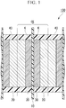
- FIG. 1 is a schematic cross-sectional view of a redox flow battery of a first embodiment.
- a redox flow battery 100 shown in FIG. 1 includes: an ion-exchange membrane 10; collector plates 20; and electrodes 30.
- the collector plates 20 and the electrodes 30 are surrounded by a cell frame 40.
- the electrode 30 is provided in an electrode compartment K formed by the ion-exchange membrane 10, the collector plate 20, and the cell frame 40. An electrolyte supplied to the electrode compartment K is prevented from leaking to the outside by the cell frame 40.
- the redox flow battery 100 shown in FIG. 1 has a cell-stack structure where a plurality of cells CE are stacked on top of each other.
- the number of stacks of the cells CE can be appropriately changed depending on applications, and only a single cell may be provided. In the case where the plurality of cells CE are connected together in series, a practical voltage is obtained.
- One cell CE includes the ion-exchange membrane 10; two electrodes 30 servings as a positive electrode and a negative electrode between which the ion-exchange membrane 10 is interposed; and the collector plates 20 between which the two electrodes 30 are interposed.
- a stacking direction of the cell-stack structure where the cells CE are stacked on top of each other may be simply referred to as a "stacking direction", and the direction of a plane vertical to the stacking direction of the cell-stack structure may be simply referred to as an "in-plane direction”.
- a cation-exchange membrane can be preferably used as the ion-exchange membrane 10.
- the material of the ion-exchange membrane 10 include a perfluorocarbon polymer having a sulfo group, a hydrocarbon-based polymer compound having a sulfo group, a polymer compound doped with an inorganic acid such as phosphoric acid, an organic/inorganic hybrid polymer in which a part thereof is substituted with a proton-conductive functional group, and a proton conductor in which a polymer matrix is impregnated with a phosphoric acid solution or a sulfuric acid solution.
- a perfluorocarbon polymer having a sulfo group is preferably used, and a Nafion (registered trademark) is more preferably used.
- the collector plate 20 is a current collector having the function of transferring electrons to or from the electrode 30. In the case where both surfaces of the collector plate 20 can be used as a current collector, the collector plate 20 may be referred to as a bipolar plate.
- the collector plate of the embodiment is more preferably used in a redox flow battery.
- the collector plate 20 can be made from a material having conductivity.
- a conductive material containing carbons can be used.
- the material include conductive resin consisting of graphite and an organic polymer compound, conductive resin in which a part of graphite is substituted with at least one of a carbon black and a diamond-like carbon, a mold material obtained by kneading carbon and resin.
- a mold material obtained by kneading carbon and resin and molding the kneaded product is preferably used.
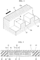
- FIG. 2 is a plan view of the collector plate 20 stored in the cell frame 40 as seen in the stacking direction.
- a plurality of flow paths C are provided on a surface of the collector plate 20 positioned on the side of the ion-exchange membrane 10 (the ion-exchange membrane 10 side surface).
- a wall portion (internal wall 22) is provided at a position between grooves of the plurality of flow paths C. It is also referred that a plurality of the internal walls 22 are provided, and the flow path C is formed between the internal walls 22.
- a recessed region (portion) 20A is formed on the surface of the collector plate 20 positioned on the side of the ion-exchange membrane 10 (the ion-exchange membrane 10 side surface).
- FIG. 3 is a schematic cross-sectional view of the collector plate as the redox flow battery of the first embodiment is cut along an A-A plane in FIG.
- the recessed region 20A includes the flow paths C and a region into which a first electrode 31 (will be described later) is fitted.
- a peripheral edge wall 21 may be provided on one surface of the collector plate 20, and the peripheral edge wall 21 defines the recessed region 20A.
- the peripheral edge wall 21 surrounds a predetermined region containing the flow path C.
- the region surrounded by the peripheral edge wall 21 contains the recessed region 20A, and has an arbitrarily selected shape such as square, substantially square, or rectangle.
- An electrolyte is supplied from an opening portion 21i of the peripheral edge wall 21 into the recessed region 20A surrounded by the peripheral edge wall 21.
- the electrolyte supplied from the opening portion 21i of the peripheral edge wall 21 diffuses throughout the recessed region 20A, and then is exhausted from an exhaust path 23. Because the electrolyte diffuses throughout the recessed region 20A in the in-plane direction, the entire surface of the electrode 30 in the in-plane direction can be used. As a result, the cell resistance of the redox flow battery decreases, and charge and discharge characteristics are improved.
- FIG. 4 is a perspective magnified view of main elements of the collector plate 20.
- a first surface 21a of the peripheral edge wall 21 (exposed surface on the side (upper side in FIG. 4 ) of one surface where the flow path is formed) is provided with protrusions and recessions restricting a flow of the electrolyte.
- the first surface 21a of the peripheral edge wall 21 is also referred to as a surface that is positioned toward the stacking direction, and faces the electrode 30 or the ion-exchange membrane 10.
- the protrusions and recessions are formed in a direction intersecting an extension direction D of the peripheral edge wall 21.
- the directions of arrows in FIGS. 2 and 4 represent the extension direction D.
- the protrusions and recessions are, for example, streaky grooves as shown in FIG. 4 .
- the electrolyte In the case where the protrusions and recessions are cyclically formed in the first surface 21a of the peripheral edge wall 21 in the direction intersecting the extension direction D, it becomes difficult for the electrolyte to flow from the recessed region 20A to the exhaust path 23. That is, before reliably diffusing throughout the recessed region 20A, the electrolyte is restricted from passing over the first surface 21a of the peripheral edge wall 21, and flowing to the exhaust path 23. As a result, the electrolyte reliably diffuses throughout the recessed region 20A, and is supplied to the entire surface of the electrode 30 in the in-plane direction.
- the first surface 21a of the peripheral edge wall 21 may not necessarily have a pattern of protrusions and recessions.
- the surface roughness (Ra) of the first surface 21a of the peripheral edge wall 21 which is measured along a direction perpendicular to the extension direction D of the peripheral edge wall 21 may be greater than the surface roughness (Ra) measured along the extension direction D of the peripheral edge wall 21.
- the electrolyte can be restricted from flowing from the recessed region 20A to the exhaust path 23.
- Grooves may be formed in the first surface 21a of the peripheral edge wall 21 along the extension direction D of the peripheral edge wall 21.
- the internal walls 22 form the flow paths C through which the electrolyte flows in the recessed region 20A.
- the shape of the flow path C and the shape of the internal wall 22 regulated by the plurality of flow paths C are not limited to a specific shape.
- the internal walls 22 shown in FIG. 2 include a first flow path C1 that is a part of the flow path C extending from the opening portion 21i in one direction, and second flow paths C2 that are connected with the first flow path C1 and branch from the first flow path C1 in a direction intersecting the first flow path C1.
- the supplied electrolyte flows along the first flow path C1, and diffuses in the second flow paths C2. That is, the electrolyte easily diffuses in the recessed region 20A in the in-plane direction.
- the configuration of the collector plate 20 is not limited to the configuration shown in FIG. 2 , and the collector plate 20 can have various configurations.
- FIG. 4 is a perspective magnified view of main elements of the collector plate 20.
- a first surface 22a of an internal wall 22 (exposed surface on the side (upper side in FIG. 4 ) of one surface of the internal wall between a plurality of the flow paths) is a surface disposed on the side of the ion-exchange membrane 10.
- the first surface 22a of the internal wall 22 is also referred to as a surface that is positioned toward the stacking direction, and faces the electrode 30.
- the flow path C between the internal walls 22 is shown to have a rectangular cross-sectional shape.
- the flow path C may have a semicircular or triangular cross-sectional shape.
- the first surface 22a of the internal wall 22 is in direct contact with the electrode 30.
- the arithmetic surface roughness (Ra) of the first surface 22a of the internal wall 22 is greater than or equal to 1 ⁇ m and less than or equal to 300 ⁇ m.
- the arithmetic surface roughness (Ra) is preferably greater than or equal to 2 ⁇ m and less than or equal to 250 ⁇ m, and more preferably greater than or equal to 5 ⁇ m and less than or equal to 200 ⁇ m.
- the arithmetic surface roughness is measured based on JIS B0601. A measurement length is set to 2 mm, and is an average value of Ra measured at three arbitrary points.
- the arithmetic surface roughness is also referred to as a mean surface roughness or simply a surface roughness.
- a contact area between the electrode 30 and the internal wall 22 is considered to become large.
- the contact area between the electrode 30 and the internal wall 22 is large, the transferring of electrons occurring in the electrolyte becomes smooth, and the cell resistance of the redox flow battery decreases.
- the redox flow battery is assembled by stacking the collector plates 20, the electrodes 30, and the ion-exchange membrane 10 on top of each other which are separate members, and interposing the collector plates 20, the electrodes 30, and the ion-exchange membrane 10 between themselves in the stacking direction. For this reason, the position of the electrode 30 may shift relative to the position of the collector plate 20 in the in-plane direction. In the case where the position of the electrode 30 shifts relative to the position of the collector plate 20, the electrolyte flows out without passing through the electrode 30, and charge and discharge capacity of the redox flow battery decreases.
- the positioning of the electrode 30 during the assembly of the redox flow battery becomes stable. That is, a decrease in the charge and discharge capacity of the redox flow battery is prevented.
- the state of contact between the first surface 22a of the internal wall 22 and carbon fibers of the electrode 30 is also one of major factors for increasing a contact area between the collector plate 20 and the electrode 30.
- the carbon fibers of the electrode 30 are greatly large relative to the mean surface roughness (Ra) of the first surface 22a of the internal wall 22, the carbon fibers cannot enter the protrusions and recessions of the first surface 22a. In this case, the carbon fibers are in point contact with the protrusions and recessions of the first surface 22a.
- the carbon fibers are in surface contact with the protrusions and recessions of the first surface 22a so as to increase the contact area between the electrode 30 and the collector plate 20.
- the arithmetic surface roughness (Ra) of the first surface 22a of the internal wall 22 is preferably greater than or equal to 1.0 time and less than or equal to 100 times the fiber diameter of the carbon fibers (will be described later) of the electrode 30, and more preferably greater than or equal to 1.2 times and less than or equal to 50 times the fiber diameter.
- the contact area between the electrode 30 and the collector plate 20 can be further increased.
- the carbon fibers of the electrode 30 In the case where the fiber diameter of the carbon fibers of the electrode 30 is greatly large relative to the surface roughness (Ra) of the first surface 22a of the internal wall 22, the carbon fibers cannot enter the protrusions and recessions of the first surface 22a. In this case, the carbon fibers are in point contact with the protrusions and recessions of the first surface 22a.
- the surface roughness (Ra) of the first surface 22a of the internal wall 22 is set to be in the above-described range, the carbon fibers can enter the protrusions and recessions, and are in surface contact with the first surface 22a. As a result, the contact area between the electrode 30 and the collector plate 20 increases.
- a width W of the internal wall 22 is preferably greater than or equal to 0.5 mm and less than or equal to 30 mm, and more preferably greater than or equal to 0.5 mm and less than or equal to 10 mm.
- the electrolyte is supplied along the flow path C. For this reason, when a part of the electrode 30 positioned (present) on the flow path C is compared to a part of the electrode 30 positioned on the internal wall 22, the electrolyte is easily supplied to the part of the electrode 30 positioned on the flow path C. In the case where the width W of the internal wall 22 is small, the electrolyte is easily supplied to the part of the electrode 30 on the internal wall 22.
- Reactions of the redox flow battery occur at an interface between the electrolyte and the electrode 30. For this reason, in the case where the width of the internal wall 22 is sufficiently small, the electrolyte is sufficiently supplied in the in-plane direction, an increase in the cell resistance is prevented, and a decrease in the charge and discharge capacity of the redox flow battery is prevented.
- the internal walls 22 form a flow path for a flow of the electrolyte. For this reason, it is possible to ensure sufficient strength by designing the internal wall 22 to have a certain level of thickness. As a result, there are advantages such as being easily processed.
- FIG. 5 is a schematic cross-sectional view as the redox flow battery of the first embodiment is cut along the A-A plane in FIG. 2 .
- a conductive sheet containing carbon fibers can be used as the electrode 30.
- the carbon fiber referred herein is fibrous carbon, and examples of the fibrous carbon include carbon fibers and carbon nanotubes.
- the electrode 30 contains carbon fibers, a contact area between the electrolyte and the electrode 30 increases, and the reactivity of the redox flow battery 100 increases.
- the electrode 30 contains carbon nanotubes having a diameter of less than or equal to 1 ⁇ m
- a fiber diameter of the carbon nanotubes is small, and thus it is possible to increase the contact area between the electrolyte and the electrode 30.
- the electrode 30 contains carbon fibers having a diameter of greater than or equal to 1 ⁇ m
- the conductive sheet becomes strong, and it becomes difficult to break the conductive sheet.
- a carbon felt, a carbon paper, or a carbon-nanotube sheet can be used as the conductive sheet containing carbon fibers.
- a layer of the electrode 30 may be provided in the stacking direction, or a plurality of layers of the electrodes 30 may be provided in the stacking direction.
- the electrode 30 may include the first electrode 31, the second electrode 32, and the liquid outlet layer 33 which are sequentially disposed from the side of the collector plate 20.
- the first electrode 31 is fitted into the recessed region 20A of the collector plate 20, and is present closer to the collector plate 20 than a first surface 21a of the peripheral edge wall 21.
- the first electrode 31 is fitted into a region which is surrounded by a side surface of the peripheral edge wall 21 and the first surfaces 22a of the internal walls 22 in the recessed region 20A.
- the second electrode 32 is disposed closer to the ion-exchange membrane 10 than the first surface 21a of the peripheral edge wall 21, and stretches throughout a region surrounded by the cell frame 40.
- the liquid outlet layer 33 stretches throughout the region surrounded by the cell frame 40, and the liquid outlet layer 33 preferably allows the electrolyte to easily flow therethrough more easily than the second electrode 32.
- the liquid outlet layer 33 may be a porous sheet having a large number of holes for permeation of liquid, and may not necessarily have conductivity.
- a relationship between the fiber diameter of the carbon fibers of the electrode 30 and the mean surface roughness (Ra) of the first surface 22a of the internal wall 22 is important for increasing the contact area between the collector plate 20 and the electrode 30.
- a fiber diameter of carbon fibers contained in an electrode layer which is in contact with the internal wall 22, that is, a fiber diameter of carbon fibers contained in the first electrode 31 in FIG. 5 becomes important.
- the mean surface roughness (Ra) of the first surface 22a of the internal wall 22 is determined relative to a large fiber diameter of carbon fibers which are contained in the electrode 30 (or the first electrode 31).
- the carbon fibers having a large fiber diameter are fibers that are determined to be thick at an observation of 1 cm square of the surface of the electrode 30 in contact with the collector plate 20 by using an optical microscope or a scanning electron microscope (SEM).
- SEM scanning electron microscope
- the first electrode 31 preferably has a liquid permeability greater than that of the second electrode 32.
- the liquid permeability of the first electrode 31 in the in-plane direction is greater than that of the second electrode 32 in the stacking direction, a flow of the electrolyte having flown into the electrode compartment K is restricted by the second electrode 32, and the electrolyte diffuses in the in-plane direction.
- the electrolyte diffuses throughout the recessed region 20A in the in-plane direction, the electrolyte flows to the entire surface of the second electrode 32 more uniformly and easily.
- the liquid outlet layer 33 is porous, and the electrolyte having flown out from the second electrode 32 is guided to the exhaust path by the liquid outlet layer 33.
- the liquid outlet layer 33 preferably has a liquid permeability greater than that of the second electrode 32.
- the liquid permeability of the liquid outlet layer 33 in the in-plane direction is greater than that of the second electrode 32 in the stacking direction, a difference in a flow of the electrolyte in a part of the second electrode 32 in the vicinity of the exhaust path 23 becomes small.
- charge and discharge reactions can occur on the entire surface of the second electrode 32, and the cell resistance decreases.
- the liquid outlet layer 33 is made from a conductive material, and serves as an electrode (third electrode) which is a part of the electrode 30, the cell resistance further decreases.
- the materials of the first electrode 31 can be used as exemplary examples of the conductive material.
- the liquid permeability can be evaluated by a Darcy's law permeability (hereinbelow, may be simply referred to as a permeability).
- a permeability typically, the Darcy's law is used to represent the permeability of a porous medium, and is also applied to members other than porous materials for the sake of convenience.
- a permeability in a direction where the lowest permeability is observed is adopted.
- a Darcy's law permeability k (m 2 ) is calculated based on a relationship with a permeation flux (m/sec) of a liquid which is represented by the following equation where when the liquid having a viscosity ⁇ (Pa ⁇ sec) permeates through a member having a cross-sectional area S (m 2 ) and a length L (m) at a flow rate Q (m 3 /sec), a pressure difference between a liquid inlet side and a liquid outlet side of the member is represented as ⁇ P (Pa).
- Q S k ⁇ ⁇ ⁇ ⁇ P L
- the permeability of the first electrode 31 is preferably greater than or equal to 100 times, more preferably greater than or equal to 300 times, and further more preferably greater than or equal to 1,000 times that of the second electrode 32.
- the first electrode 31 is made from a carbon felt or a carbon paper which contains carbon fibers having a fiber diameter of greater than or equal to 1 ⁇ m
- the second electrode 32 is made from a carbon-nanotube sheet which contains carbon nanotubes having a fiber diameter of less than or equal to 1 ⁇ m.
- the permeability of the first electrode 31 represents a permeability in the in-plane direction
- the permeability of the second electrode 32 represents a permeability in the stacking direction (normal direction of the in-plane direction).
- the liquid outlet layer 33 preferably has a liquid permeability greater than that of the second electrode 32.
- the reason is that the electrolyte having passed through the second electrode 32 is required to be quickly exhausted to the exhaust path 23.
- the permeability of the liquid outlet layer 33 is preferably greater than or equal to 50 times, more preferably greater than or equal to 100 times, further more preferably greater than or equal to 300 times, and particularly preferably greater than or equal to 1,000 times that of the second electrode 32.
- the exemplary examples of the materials of the first electrode 31 can be used as the material of the liquid outlet layer 33.
- the permeability of the liquid outlet layer 33 represents a permeability in the in-plane direction.
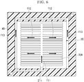
- FIG. 6 is a view showing a flow of the electrolyte in the redox flow battery 100 of the first embodiment.
- the electrolyte is supplied into the electrode compartment K of the redox flow battery 100 from an inlet port provided in the cell frame 40.
- the electrolyte supplied into the electrode compartment K reacts with the electrode 30 in the electrode compartment K. Ions occurring at the reactions flow between the electrodes 30 via the ion-exchange membrane 10, and charge and discharge occurs.
- the electrolyte after the reactions is exhausted from an outlet port provided in the cell frame 40.
- the electrolyte is supplied from the opening portion 21i of the peripheral edge wall 21 into the recessed region 20A in the electrode compartment K (flow fl 1).
- the supplied electrolyte flows along the internal walls 22, and diffuses in the recessed region 20A in the in-plane direction (flow f12). Then the electrolyte passes through the electrode 30, and is exhausted from the exhaust path 23 (flow f13).
- the redox flow battery of the embodiment it is possible to increase the contact area between the electrode and the collector plate. In the case where the contact area between the electrode and the collector plate is large, the transferring of electrons occurring in the electrolyte becomes smooth, and it is possible to decrease the cell resistance of the redox flow battery.
- the accuracy of assembling the redox flow battery is improved. For this reason, a decrease in the charge and discharge capacity of the redox flow battery is prevented.
- a planar plate of 50 mm ⁇ 50 mm made from a resin complex containing carbons was prepared for the collector plate 20.
- the cross-sectional size of the electrode compartment K in the in-plane direction surrounded by the cell frame 40 was set to 50 mm ⁇ 50 mm.
- the collector plate 20 included the first flow path C1 and the second flow paths C2 which were defined by the internal walls 22.
- the width of the peripheral edge wall 21 was set to 1.5 mm
- the width of the internal wall 22 was set to 1 mm
- the width of the first flow path C1 was set to 1 mm
- the width of the second flow path C2 was set to 1 mm.
- the internal walls 22 and the second flow paths C2 were disposed to have line symmetry with respect to the first flow path C1, respectively.
- Twenty three internal walls 22 and twenty four second flow paths C2 were disposed on one surface side of the first flow path C1. The similar configuration was provided on the other surface side of the first flow path C1.
- the arithmetic surface roughness of the first surface 22a of the internal wall 22 was set to 27 ⁇ m.
- the first surface 22a of the internal wall 22 was subjected to blasting by blowing ceramic particles thereonto.
- the blasting was performed in such a manner that the amount of ejected ceramic particles was changed, and a predetermined roughness was obtained.
- the blasting was performed before the first flow path C1 and the second flow paths C2 were formed.
- Electrode 30 Three layers of electrodes stacked on top of each other in the stacking direction was used as the electrode 30.
- a carbon fiber sheet A was used as the first electrode 31.
- a fiber diameter of carbon fibers of the electrode 30 was 8 ⁇ m. That is, the arithmetic surface roughness (Ra) of the first surface 22a of the internal wall 22 was 3.4 times the fiber diameter of the carbon fibers.
- 11 layers of the first electrodes of 50 mm ⁇ 50 mm were stacked and compressed in a stacking direction in a permeability measurement cell having a cross-sectional area of 1.35 cm 2 (a width of 50 mm and a height of 2.7 mm) and a length of 5 cm to be installed therein, and the permeability of the first electrode was measured.
- Water (20°C) was permeated through the permeation measurement cell at a permeation flux of 0.5 cm/sec, and a pressure difference (outlet pressure - inlet pressure) caused by the stacked first electrodes was measured, and the permeability was calculated.
- the permeability of the first electrode used in Example 1 was 3.5 ⁇ 10 -11 m 2 .
- a conductive sheet including carbon nanotubes was used as the second electrode.
- the conductive sheet was produced by the following method.
- First carbon nanotubes having an average fiber diameter of 150 nm and an average fiber length of 15 ⁇ m and second carbon nanotubes having an average fiber diameter of 15 nm and an average fiber length of 3 ⁇ m were mixed together in pure water.
- the mixing ratio of the first carbon nanotubes was set to 90 parts by mass and the mixing ratio of the second carbon nanotubes was set to 10 parts by mass relative to 100 parts by mass of the total of the first carbon nanotubes and the second carbon nanotubes.
- a polyisothionaphthene sulfonic acid which was a water-soluble conductive polymer was added.
- the mixing ratio of the added water-soluble conductive polymer was set to 1 part by mass relative to 100 parts by mass of the total of the first carbon nanotubes and the second carbon nanotubes.
- the obtained mixture was processed by a wet-type jet mill; and thereby, a dispersed solution of carbon nanotubes was obtained.
- 50 parts by mass of carbon fibers having an average fiber diameter of 7 ⁇ m and an average fiber length of 0.13 mm were added to the dispersed solution relative to 100 parts by mass of the total of the first carbon nanotubes, the second carbon nanotubes, and the carbon fibers.
- the mixture was stirred by a magnetic stirrer; and thereby, the carbon nanotubes and the like were dispersed.
- the dispersed solution was filtered through a filter paper, and the residue together with the filter paper were dehydrated, a dehydrated residue was compressed by a press machine, and dried; and thereby, the conductive sheet containing the carbon nanotubes was produced.
- the permeability of the produced conductive sheet having the length L was evaluated, and the length L different from a length of an electrode (second electrode in Example 1) for actual use could be adopted because the pressure difference ⁇ P and the length L were in a proportional relationship.
- 30 layers of the produced conductive sheets were stacked, and Ni mesh sheets having 60 meshes and made from a Ni wire of ⁇ 0.10 mm were disposed on both surfaces of the stacked conductive sheets, and the stacked conductive sheets were compressed so that the total thickness became 1 cm, and the stacked conductive sheets were installed in a permeation measurement cell having a cross-sectional area of 1.35 cm 2 (a width of 50 mm and a height of 2.7 mm) and a length of 1 cm, and the permeability of the compressed conductive sheets was measured.
- a carbon fiber (CF) paper (manufactured by SGL Ltd. Co. and GDL10AA) having porosity was prepared as the liquid outlet layer.
- 11 layers of CF papers of 50 mm ⁇ 50 mm were stacked and compressed in a stacking direction in a permeability measurement cell having a cross-sectional area of 1.35 cm 2 (a width of 50 mm and a height of 2.7 mm) and a length of 5 cm to be installed therein, and the permeability of the CF paper was measured.
- Water (20°C) was permeated through the permeation measurement cell at a permeation flux of 0.5 cm/sec, and a pressure difference (outlet pressure - inlet pressure) caused by the stacked CF papers was measured, and the permeability was calculated.
- the permeability of the liquid outlet layer used in Example 1 was 4.1 ⁇ 10 -11 m 2 .
- Nafion N212 (registered trademark and manufactured by DuPont Ltd. Co.) was used as the ion-exchange membrane 10.
- the thickness of the ion-exchange membrane 10 was approximately 50 ⁇ m.
- a secondary redox flow battery of Example 1 was assembled by sequentially stacking the prepared members on top of each other.
- the secondary redox flow battery had a cell-stack structure where five layers of cells were stacked on top of each other.
- An aqueous solution of 4.5 mol/L H 2 SO 4 having a concentration of tetravalent vanadium ions of 1.8 mol/L was used as an electrolyte for a positive electrode.
- An aqueous solution of 4.5 mol/L H 2 SO 4 having a concentration of trivalent vanadium ions of 1.8 mol/L was used as an electrolyte for a negative electrode.
- the volume of each electrolyte was set to 200 mL.
- the cell resistance of the obtained redox flow battery was measured.
- the cell resistance of the redox flow battery of Example 1 was 0.7 ⁇ cm 2 .
- a redox flow battery of Example 2 differed from that of Example 1 in that the arithmetic surface roughness of the first surface 22a of the internal wall 22 was set to 2 ⁇ m and the material of the first electrode 31 was changed to a carbon fiber sheet B (carbon fiber diameter of 1.5 ⁇ m).
- surface roughening was performed under the conditions where the amount of ejected particles and an ejection pressure were set to values less than those of Example 1.
- the arithmetic surface roughness (Ra) of the first surface 22a of the internal wall 22 was 1.3 times the fiber diameter of carbon fibers. Other configurations were set similar to those of Example 1.
- the cell resistance of the redox flow battery of Example 2 was 0.68 ⁇ cm 2 .
- a redox flow battery of Example 3 differed from that of Example 1 in that the arithmetic surface roughness of the first surface 22a of the internal wall 22 was set to 3.5 ⁇ m and the material of the first electrode 31 was changed to a carbon fiber sheet C (carbon fiber diameter of 5 ⁇ m).
- surface roughening was performed under the conditions where the amount of ejected particles was set to a value greater than that of Example 2.
- Other configurations were set similar to those of Example 1.
- the arithmetic surface roughness (Ra) of the first surface 22a of the internal wall 22 was 0.7 times the fiber diameter of carbon fibers of the electrode.
- the cell resistance of the redox flow battery of Example 3 was 0.75 ⁇ cm 2 .
- a redox flow battery of Comparative Example 1 differed from that of Example 1 in that the arithmetic surface roughness of the first surface 22a of the internal wall 22 was set to 500 ⁇ m. Surface roughening was performed using ceramic particles having a particle size greater than that of Example 1 under the conditions where the amount of ejected particles and an ejection pressure were set to values greater than those of Example 1. Other configurations were set similar to those of Example 1.
- the cell resistance of the redox flow battery of Comparative Example 1 was 1.5 ⁇ cm 2 .
- a redox flow battery of Comparative Example 2 differed from that of Example 1 in that the arithmetic surface roughness of the first surface 22a of the internal wall 22 was set to 0.5 ⁇ m. Surface roughening was performed under the conditions where the amount of ejected particles and an ejection pressure were set to values less than those of Example 2. Other configurations were set similar to those of Example 1.
- the cell resistance of the redox flow battery of Comparative Example 1 was 1.2 ⁇ cm 2 .
- the contact area between the electrode and the collector plate is considered to be large, and thus the cell resistance can be decreased. Therefore, the present invention can be preferably applied to a redox flow battery of a high-capacity storage battery.
Landscapes
- Life Sciences & Earth Sciences (AREA)
- Engineering & Computer Science (AREA)
- Manufacturing & Machinery (AREA)
- Sustainable Development (AREA)
- Sustainable Energy (AREA)
- Chemical & Material Sciences (AREA)
- Chemical Kinetics & Catalysis (AREA)
- Electrochemistry (AREA)
- General Chemical & Material Sciences (AREA)
- Fuel Cell (AREA)
- Inert Electrodes (AREA)
Applications Claiming Priority (2)
| Application Number | Priority Date | Filing Date | Title |
|---|---|---|---|
| JP2016236721 | 2016-12-06 | ||
| PCT/JP2017/043786 WO2018105646A1 (ja) | 2016-12-06 | 2017-12-06 | 集電板及びレドックスフロー電池 |
Publications (2)
| Publication Number | Publication Date |
|---|---|
| EP3553860A1 true EP3553860A1 (de) | 2019-10-16 |
| EP3553860A4 EP3553860A4 (de) | 2020-07-29 |
Family
ID=62492286
Family Applications (1)
| Application Number | Title | Priority Date | Filing Date |
|---|---|---|---|
| EP17877872.6A Withdrawn EP3553860A4 (de) | 2016-12-06 | 2017-12-06 | Kollektorplatte und redox-flow-batterie |
Country Status (5)
| Country | Link |
|---|---|
| US (1) | US20190393533A1 (de) |
| EP (1) | EP3553860A4 (de) |
| JP (1) | JPWO2018105646A1 (de) |
| CN (1) | CN109983607A (de) |
| WO (1) | WO2018105646A1 (de) |
Families Citing this family (3)
| Publication number | Priority date | Publication date | Assignee | Title |
|---|---|---|---|---|
| EP3553861A4 (de) * | 2016-12-06 | 2020-07-29 | Showa Denko K.K. | Kollektorplatte und redox-flow-batterie |
| JP2020035732A (ja) * | 2018-08-24 | 2020-03-05 | 旭化成株式会社 | レドックスフロー電池用電極 |
| CN110534775B (zh) * | 2019-09-03 | 2022-04-05 | 中国科学院金属研究所 | 一种液流电池正负极电解液迁移控制方法 |
Family Cites Families (12)
| Publication number | Priority date | Publication date | Assignee | Title |
|---|---|---|---|---|
| JP2920230B2 (ja) * | 1988-11-30 | 1999-07-19 | 東洋紡績株式会社 | レドックスフロー型電池 |
| JPH11297338A (ja) * | 1998-04-10 | 1999-10-29 | Nisshinbo Ind Inc | 固体高分子型燃料電地用セパレータ及びその製造方法 |
| JP2002246035A (ja) * | 2001-02-16 | 2002-08-30 | Sumitomo Electric Ind Ltd | 電池用電極およびそれを用いた電池 |
| JP3996762B2 (ja) * | 2001-11-21 | 2007-10-24 | 住友電気工業株式会社 | レドックスフロー電池用電極 |
| JP4747804B2 (ja) * | 2005-11-25 | 2011-08-17 | パナソニック電工株式会社 | 燃料電池用セパレータの製造方法 |
| WO2013095378A1 (en) | 2011-12-20 | 2013-06-27 | United Technologies Corporation | Flow battery with mixed flow |
| WO2014109957A1 (en) * | 2013-01-11 | 2014-07-17 | Graftech International Holdings Inc. | Improved bipolar plate for flow batteries |
| CN205752372U (zh) * | 2013-03-15 | 2016-11-30 | 格拉弗技术国际控股有限公司 | 用于液流电池的电极双极板的组件 |
| JP2015122231A (ja) | 2013-12-24 | 2015-07-02 | 住友電気工業株式会社 | レドックスフロー電池 |
| DE102014109321B4 (de) * | 2014-07-03 | 2025-07-03 | Deutsches Zentrum für Luft- und Raumfahrt e.V. | Verfahren zur Herstellung einer Bipolarplatte, Bipolarplatte für eine elektrochemische Zelle und elektrochemische Zelle |
| CN106450404A (zh) * | 2015-07-27 | 2017-02-22 | 大连融科储能技术发展有限公司 | 液流电池电堆 |
| CN105810987B (zh) * | 2016-04-26 | 2018-07-03 | 中国东方电气集团有限公司 | 液流电池 |
-
2017
- 2017-12-06 EP EP17877872.6A patent/EP3553860A4/de not_active Withdrawn
- 2017-12-06 JP JP2018555035A patent/JPWO2018105646A1/ja active Pending
- 2017-12-06 US US16/466,465 patent/US20190393533A1/en not_active Abandoned
- 2017-12-06 CN CN201780072720.0A patent/CN109983607A/zh active Pending
- 2017-12-06 WO PCT/JP2017/043786 patent/WO2018105646A1/ja not_active Ceased
Also Published As
| Publication number | Publication date |
|---|---|
| CN109983607A (zh) | 2019-07-05 |
| EP3553860A4 (de) | 2020-07-29 |
| WO2018105646A1 (ja) | 2018-06-14 |
| US20190393533A1 (en) | 2019-12-26 |
| JPWO2018105646A1 (ja) | 2019-10-24 |
Similar Documents
| Publication | Publication Date | Title |
|---|---|---|
| US10680248B2 (en) | Electrode material, electrode of redox flow battery, and redox flow battery | |
| JP4790873B2 (ja) | 膜電極接合体及びその製造方法、並びに燃料電池 | |
| EP3240071B1 (de) | Elektrode für redoxflussbatterien sowie redoxflussbatterie | |
| DE102013225159B4 (de) | Anordnung elektrochemischer Zellen | |
| JP7486931B2 (ja) | 電気化学反応器フローガイドの製造方法 | |
| US20050250002A1 (en) | Composite catalyst layer, electrode and passive mixing flow field for compressionless fuel cells | |
| EP3553859A1 (de) | Kollektorplatte und redox-flow-batterie | |
| DE102008038202A1 (de) | PEM-Brennstoffzelle mit verbessertem Wassermanagement | |
| EP3553860A1 (de) | Kollektorplatte und redox-flow-batterie | |
| TWI648903B (zh) | 氧化還原液流電池 | |
| EP3522279A1 (de) | Redox-flow-batterie | |
| EP3734729A1 (de) | Elektrode für redox-flussbatterie sowie redox-flussbatterie | |
| US10707514B2 (en) | Redox flow battery | |
| US10790531B2 (en) | Collector plate and redox flow battery | |
| DE112012001206T5 (de) | Brennstoffzellen-System | |
| DE102009043208A1 (de) | Materialauslegung, um eine Leistungsfähigkeit einer Brennstoffzelle bei hoher Mittentemperatur mit ultradünnen Elektroden zu ermöglichen | |
| JP2004303558A (ja) | 燃料電池 | |
| JP2013037932A (ja) | 電極−膜−枠接合体の製造方法及び燃料電池の製造方法 | |
| CN110024195A (zh) | 集电板和氧化还原液流电池 | |
| CN121662852A (zh) | 一种燃料电池的气体扩散层、燃料电池以及燃料电池堆 | |
| JP2019012694A (ja) | 集電板 |
Legal Events
| Date | Code | Title | Description |
|---|---|---|---|
| STAA | Information on the status of an ep patent application or granted ep patent |
Free format text: STATUS: THE INTERNATIONAL PUBLICATION HAS BEEN MADE |
|
| PUAI | Public reference made under article 153(3) epc to a published international application that has entered the european phase |
Free format text: ORIGINAL CODE: 0009012 |
|
| STAA | Information on the status of an ep patent application or granted ep patent |
Free format text: STATUS: REQUEST FOR EXAMINATION WAS MADE |
|
| 17P | Request for examination filed |
Effective date: 20190701 |
|
| AK | Designated contracting states |
Kind code of ref document: A1 Designated state(s): AL AT BE BG CH CY CZ DE DK EE ES FI FR GB GR HR HU IE IS IT LI LT LU LV MC MK MT NL NO PL PT RO RS SE SI SK SM TR |
|
| AX | Request for extension of the european patent |
Extension state: BA ME |
|
| DAV | Request for validation of the european patent (deleted) | ||
| DAX | Request for extension of the european patent (deleted) | ||
| A4 | Supplementary search report drawn up and despatched |
Effective date: 20200630 |
|
| RIC1 | Information provided on ipc code assigned before grant |
Ipc: H01M 8/18 20060101ALI20200624BHEP Ipc: H01M 8/026 20160101AFI20200624BHEP Ipc: H01M 8/10 20160101ALI20200624BHEP |
|
| STAA | Information on the status of an ep patent application or granted ep patent |
Free format text: STATUS: THE APPLICATION IS DEEMED TO BE WITHDRAWN |
|
| 18D | Application deemed to be withdrawn |
Effective date: 20210128 |