EP3553878A1 - Abstimmbarer filter und abstimmbare filtrierungsvorrichtung - Google Patents
Abstimmbarer filter und abstimmbare filtrierungsvorrichtung Download PDFInfo
- Publication number
- EP3553878A1 EP3553878A1 EP16924959.6A EP16924959A EP3553878A1 EP 3553878 A1 EP3553878 A1 EP 3553878A1 EP 16924959 A EP16924959 A EP 16924959A EP 3553878 A1 EP3553878 A1 EP 3553878A1
- Authority
- EP
- European Patent Office
- Prior art keywords
- component
- adjustable component
- drive mechanism
- adjustable
- tunable filter
- Prior art date
- Legal status (The legal status is an assumption and is not a legal conclusion. Google has not performed a legal analysis and makes no representation as to the accuracy of the status listed.)
- Granted
Links
Images

Classifications
-
- H—ELECTRICITY
- H03—ELECTRONIC CIRCUITRY
- H03J—TUNING RESONANT CIRCUITS; SELECTING RESONANT CIRCUITS
- H03J1/00—Details of adjusting, driving, indicating, or mechanical control arrangements for resonant circuits in general
- H03J1/06—Driving or adjusting arrangements; combined with other driving or adjusting arrangements, e.g. of gain control
- H03J1/08—Toothed-gear drive; Worm drive
-
- H—ELECTRICITY
- H01—ELECTRIC ELEMENTS
- H01P—WAVEGUIDES; RESONATORS, LINES, OR OTHER DEVICES OF THE WAVEGUIDE TYPE
- H01P1/00—Auxiliary devices
- H01P1/20—Frequency-selective devices, e.g. filters
- H01P1/207—Hollow waveguide filters
-
- H—ELECTRICITY
- H01—ELECTRIC ELEMENTS
- H01P—WAVEGUIDES; RESONATORS, LINES, OR OTHER DEVICES OF THE WAVEGUIDE TYPE
- H01P3/00—Waveguides; Transmission lines of the waveguide type
- H01P3/12—Hollow waveguides
Definitions
- Embodiments of the present invention relate to the field of electronic communications technologies, and in particular, to a tunable filter and a tunable filtering device.
- a tunable filter is an important constituent part of a microwave communications system, and is widely applied to aspects such as frequency-hopping radio, electronic countermeasure, a multifunctional receiver, and a dynamic frequency allocation system.
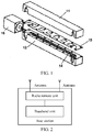
- a rectangular waveguide tube in the tunable E-plane filter is divided, at a central position of an H plane of the rectangular waveguide tube, into a first waveguide part 11 and a second waveguide part 12 along an E plane of the rectangular waveguide tube, and a metal plate 13 disposed parallel to the E plane is sandwiched between the first waveguide part 11 and the second waveguide part 12.
- at least one dielectric plate 14 is further disposed along a longitudinal extension direction of the metal plate 13, and the at least one dielectric plate 14 is connected to an external drive mechanism 15.
- the external drive mechanism 15 may externally change a relative position relationship between the dielectric plate 14 and the metal plate 13. In other words, both a position and an angle of the dielectric plate in the tunable E-plane filter may change. When the position and the angle of the dielectric plate change, an electrical length in a direction of the H plane accordingly changes, thereby changing a central frequency of the tunable E-plane filter.
- the present invention provides a tunable filter and a tunable filtering device, to resolve a problem that an existing tunable E-plane filter has a relatively poor filtering effect.
- a tunable filter includes a cavity, a filtering component that is in the cavity and that is provided on a first surface thereof with at least one through hole, a drive mechanism, and at least one first adjustable component and at least one second adjustable component that are connected to the drive mechanism and that run through the first surface of the cavity.
- one end of one first adjustable component is disposed opposite to one of the at least one through hole, and a cross sectional area of the end of the first adjustable component is greater than or equal to a cross sectional area of the other end of the first adjustable component;
- one end of one second adjustable component is disposed opposite to a position between two adjacent through holes in the at least one through hole, and a cross sectional area of the end of the second adjustable component is greater than or equal to a cross sectional area of the other end of the second adjustable component; and the drive mechanism controls the at least one first adjustable component to synchronously move, to change a distance between the at least one first adjustable component and the filtering component, and controls the at least one second adjustable component to synchronously move, to change a distance between the at least one second adjustable component and the filtering component.
- each first adjustable component is disposed opposite to one of the at least one through hole
- the change in the distance between the at least one first adjustable component and the filtering component causes a central frequency of the tunable filter to accordingly change.
- One end of each second adjustable component is disposed opposite to a position between two adjacent through holes in the at least one through hole, and the change in the distance between the at least one second adjustable component and the filtering component causes bandwidth of the tunable filter to accordingly change. If the distance between the at least one first adjustable component and the filtering component increases, the central frequency of the tunable filter also increases. When the distance between the at least one second adjustable component and the filtering component is not adjusted, the bandwidth of the tunable filter increases as the central frequency increases.
- the bandwidth of the tunable filter may be changed by adjusting the distance between the at least one second adjustable component and the filtering component, so that when the central frequency increases, it is also ensured that the bandwidth of the tunable filter remains unchanged.
- the drive mechanism includes one sub drive mechanism.
- the sub drive mechanism is connected to both the at least one first adjustable component and the at least one second adjustable component; and the sub drive mechanism controls the at least one first adjustable component and the at least one second adjustable component to synchronously move.
- the sub drive mechanism in the drive mechanism includes a drive component and a drive rod that are connected by using a fastener;
- the drive component includes a drive shaft and a drive rotor; and the drive rod is connected to both the at least one first adjustable component and the at least one second adjustable component.
- the drive rotor of the drive component controls the drive shaft of the drive component to rotate, to drive the drive rod to move, so that the distance between the at least one first adjustable component and the filtering component and the distance between the at least one second adjustable component and the filtering component change.
- the sub drive mechanism in the drive mechanism further includes a fastening component located between the fastener and the drive rotor of the drive component, and at least one anti-wobble apparatus that runs through the fastening component and that is connected to the drive rod.
- the sub drive mechanism in the drive mechanism further includes a fastening component located between the fastener and the drive rotor of the drive component, and at least one elastic apparatus that runs through the fastening component and that is connected to the drive rod.
- the drive mechanism of the tunable filter may include two sub drive mechanisms.
- one of the two sub drive mechanisms is connected to the at least one first adjustable component
- the other sub drive mechanism is connected to the at least one second adjustable component
- the sub drive mechanism controls the at least one first adjustable component to synchronously move
- the other sub drive mechanism controls the at least one second adjustable component to synchronously move.
- the tunable filter further includes at least two third adjustable components that are connected to the drive mechanism, disposed at two ends of the first surface of the first cavity, and run through the first surface of the cavity.
- the drive mechanism controls the at least two third adjustable components to synchronously move, to change a distance between each of the at least two third adjustable components and the filtering component.
- the drive mechanism may include one sub drive mechanism, and the sub drive mechanism is connected to all of the at least one first adjustable component, the at least one second adjustable component, and the at least one third adjustable component.
- the sub drive mechanism controls the at least one first adjustable component, the at least one second adjustable component, and the at least one third adjustable component to synchronously move.
- the drive mechanism may alternatively include two sub drive mechanisms, one of the two sub drive mechanisms is connected to both the at least one first adjustable component and the at least one second adjustable component, and the other sub drive mechanism is connected to the at least one third adjustable component.
- the drive mechanism includes the two sub drive mechanisms, one sub drive mechanism may be connected to one type of adjustable component in the at least one first adjustable component, the at least one second adjustable component, and the at least one third adjustable component, and the other sub drive mechanism may be connected to both the other two types of adjustable components.
- the drive mechanism controls the at least one first adjustable component to synchronously move along a direction perpendicular to the first surface of the filtering component; and the drive mechanism controls the at least one second adjustable component to synchronously move along a direction perpendicular to the first surface of the filtering component.
- a tunable filtering device includes the tunable filter according to any one of the first aspect or the possible implementations of the first aspect.
- the name of the tunable filter does not constitute a limitation on devices or functional modules, and during actual implementation, these devices or functional modules may have other names.
- the devices or functional modules fall within the scope of the claims of the present invention and equivalent technologies thereof, provided that the devices or functional modules have functions that are similar to those in the present invention.
- the terms “first”, “second”, and so on are intended to distinguish between different objects but do not limit a particular order.
- the terms “including”, “including”, or any other variant thereof, are intended to cover a non-exclusive inclusion.
- a process, a method, a system, a product, or a device that includes a series of steps or units is not limited to the listed steps or units, but optionally further includes an unlisted step or unit, or optionally further includes another inherent step or unit of the process, the method, the product, or the device.
- the word "exemplary” or “for example” is used to represent giving an example, an illustration, or a description. Any embodiment or design scheme described as “example” or “for example” in the embodiments of the present invention should not be explained as being more preferable or having more advantages than another embodiment or design scheme. Exactly, use of a term such as “example” or “for example” aims to present a related concept in a specific manner.
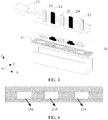
- a tunable filter provided in the embodiments of the present invention is applied to a communications system that includes a radio access network device.
- the radio access network device may be a base station.
- the base station includes: a BBU (English: Base Band Unit, baseband processing unit), an RRU (English: Radio Remote Unit, radio remote unit), and an antenna.
- the BBU may be connected to the RRU by using an optical fiber, and the RRU is connected to the antenna by using a coaxial cable and a power divider (coupler).
- one BBU may be connected to a plurality of RRUs.
- the BBU is configured to implement baseband processing functions (such as encoding, multiplexing, modulation, and spread spectrum) on a Uu interface (namely, an interface between a terminal device and the base station), an interface function on a logic interface between an RNC (English: Radio Network Controller, radio network controller) and the base station, signaling processing, local and remote operation and maintenance functions, work status monitoring and alarm information reporting functions of the base station, and the like.
- baseband processing functions such as encoding, multiplexing, modulation, and spread spectrum
- the RRU may include four modules: a digital intermediate frequency module, a transceiver module, a power amplifier module, and a filtering module.
- the digital intermediate frequency module is used for modulation and demodulation, digital frequency up-/down-conversion, digital-to-analog conversion, and the like of optical transmission.
- the transceiver module converts an intermediate frequency signal into a radio frequency signal, and after being amplified by the power amplifier module and filtered by the filtering module, the radio frequency signal is transmitted by using the antenna.
- the filtering module may be a filter in the base station.
- the embodiments of the present invention provide the tunable filter.
- bandwidth of the tunable filter may be changed by adjusting a distance between at least one second adjustable component and a filtering component in the tunable filter, so that when the central frequency of the tunable filter is increased, the bandwidth of the tunable filter remains unchanged, thereby improving a filtering effect of the filter, and preventing the bandwidth of the tunable filter from increasing as the central frequency of the tunable filter is increased.
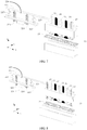
- the tunable filter provided in the embodiments of the present invention includes a cavity 20, a filtering component 21 disposed in the cavity 20, a drive mechanism 22, and at least one first adjustable component 23 and at least one second adjustable component 24 that are connected to the drive mechanism 22 and that run through a first surface of the cavity 20 (the first surface of the cavity 20 is an xoy plane in FIG. 3 ).
- the cavity 20 is represented as two parts. During actual application, the cavity 20 is a whole.
- the filtering component 21 in the embodiments of the present invention may be a metal plate.
- the first surface of the filtering component 21 (the first surface of the filtering component 21 is the xoy plane in FIG. 3 ) is provided with at least one through hole 210.
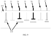
- FIG. 4 is a top view of the filtering component 21.
- the filtering component 21 is located in the cavity 20, a length of the filtering component 21 is limited, and the first surface of the filtering component 21 is provided with the at least one through hole 210. Therefore, the tunable filter provided in the embodiments of the present invention is an E-plane band-pass filter.
- the at least one through hole 210 may be evenly provided on the first surface of the filtering component 21.
- the at least one first adjustable component 23 and the at least one second adjustable component 24 are both located on one side of the filtering component 21 (in FIG. 2 , the first adjustable component 23 and the second adjustable component 24 are both located above the filtering component 21).
- the first adjustable component 23 and the second adjustable component 24 may be metal components.
- One end of one first adjustable component 23 is disposed opposite to one of the at least one through hole 210.
- a cross sectional area of the end of the first adjustable component 23 is greater than or equal to a cross sectional area of the other end of the first adjustable component 23.
- the first adjustable component 23 may be cylindrical, or may be a component including a first cylinder and a second cylinder, and a bottom surface area of the first cylinder is less than a bottom surface area of the second cylinder ( FIG. 3 shows the first adjustable component 23 in this shape).
- One end of one second adjustable component 24 is disposed opposite to a position between two adjacent through holes 210 in the at least one through hole.
- a cross sectional area of the end of the second adjustable component 24 is greater than or equal to a cross sectional area of the other end of the second adjustable component.
- a volume of the first adjustable component 23 may be the same as or different from a volume of the second adjustable component 24. This is not specifically limited in the embodiments of the present invention.
- each first adjustable component 23 and each second adjustable component 24 may be independently debugged during installation processes. In this way, an error that occurs in processing and assembly processes can be reduced, thereby reducing an error of the tunable filter.
- the drive mechanism 22 is connected to both the at least one first adjustable component 23 and the at least one second adjustable component 24.
- the drive mechanism 22 controls the at least one first adjustable component 23 to synchronously move along a direction perpendicular to the first surface of the cavity 20, to change a distance between the at least one first adjustable component 23 and the filtering component 21.
- the distance between the at least one first adjustable component 23 and the filtering component 21 may increase or decrease.
- the distance between the at least one first adjustable component 23 and the filtering component 21 is in a positive correlation relationship with the central frequency of the tunable filter.
- the central frequency of the tunable filter increases.
- the central frequency of the tunable filter decreases.
- the drive mechanism of the tunable filter further controls the at least one second adjustable component 24 to synchronously move along a direction perpendicular to the first surface of the cavity 20, to change a distance between the at least one second adjustable component 24 and the filtering component 21.
- the bandwidth of the tunable filter changes as the distance between the at least one second adjustable component 24 and the filtering component 21 changes. Therefore, for the tunable filter provided in the embodiments of the present invention, when the central frequency of the tunable filter changes, the distance between the at least one second adjustable component 24 and the filtering component 21 may be adjusted, to prevent the bandwidth of the tunable filter from increasing. In this way, the bandwidth of the tunable filter provided in the embodiments of the present invention remains unchanged.
- the drive mechanism 22 in the tunable filter provided in the embodiments of the present invention includes a sub drive mechanism 22a.
- the sub drive mechanism 22a includes a drive component 221 and a drive rod 222 that are connected by using a fastener 220.
- the drive component 221 includes a drive shaft 221a and a drive rotor 221b, and the drive rod 222 is connected to both the at least one first adjustable component 23 and the at least one second adjustable component 24.
- the drive component 221 may be a motor.
- the drive rotor 221b of the drive component 221 controls the drive shaft 221a of the drive component 221 to rotate, so that the drive rod 222 moves, to change the distance between the at least one first adjustable component 23 and the filtering component 21 and the distance between the at least one second adjustable component 24 and the filtering component 21.
- the fastener 220 in the embodiments of the present invention may be a nut, or may be a clip, or may be another component configured to perform a fastening function. This is not specifically limited in the embodiments of the present invention.
- the fastener 220 is represented by using a nut. If the fastener 220 is a nut, correspondingly, there is a thread on the drive shaft 221a of the first drive component 221.
- the sub drive mechanism 22a in the tunable filter provided in the embodiments of the present invention further includes a fastening component 223 located between the fastener 220 and the drive rotor 221b of the drive component 221, and at least one anti-wobble apparatus 224 that runs through the fastening component 223 and that is connected to the drive rod 222.
- the anti-wobble apparatus 224 may include a guide rod and a guide sleeve.
- the anti-wobble apparatus 224 is configured to improve stability of a drive rod 222 during a process in which the drive rod 222 moves or is static.
- the sub drive mechanism 22a in the tunable filter provided in the embodiments of the present invention further includes at least one elastic apparatus 225 connected to both the fastening component 223 and the drive rod 222.
- the elastic apparatus 225 may be an apparatus including at least one group of springs. In FIG. 7 , each elastic apparatus 225 is represented by using a spring.
- the stability of the drive rod 222 during the moving process can be improved, and an anti-vibration capability of the tunable filter can also be improved.
- the tunable filter provided in the embodiments of the present invention further includes at least two third adjustable components 25 that are connected to the drive rod 222, disposed at two ends of the first surface of the first cavity 20, and run through the first surface of the cavity 20.
- the drive rod 222 moves, to control the at least two third adjustable components 25 to synchronously move, to change a distance between each of the at least two third adjustable components 25 and the filtering component 21.
- an adjustment range of the central frequency of the tunable filter changes.
- FIG. 9 is a sectional view of the tunable filter when being observed from a direction in which an xoz plane in FIG. 8 is located.
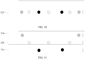
- FIG. 10 is a top view of the tunable filter shown in FIG. 8 .
- the drive mechanism of the tunable filter may alternatively include two sub drive mechanisms.
- One of the two sub drive mechanisms is connected to the at least one first adjustable component 23, and the other sub drive mechanism is connected to the at least one second adjustable component 24.
- the sub drive mechanism controls the at least one first adjustable component 23 to synchronously move; and the other sub drive mechanism controls the at least one second adjustable component 24 to synchronously move.
- each of the two sub drive mechanisms in the scenario has a same structure. Refer to a structure of the sub drive mechanism shown in any one of FIG. 5 to FIG. 8 .
- the drive mechanism of the tunable filter may alternatively include two sub drive mechanisms.
- One of the two sub drive mechanisms is connected to the at least one first adjustable component 23, and the other sub drive mechanism is connected to both the at least one second adjustable component 24 and the at least one third adjustable component 25.
- one of the two sub drive mechanisms is connected to both the at least one first adjustable component 23 and the at least one third adjustable component 25, and the other sub drive mechanism is connected to the at least one second adjustable component 24.
- one of the two sub drive mechanisms is connected to both the at least one first adjustable component 23 and the at least one second adjustable component 24, and the other sub drive mechanism is connected to the at least one third adjustable component 25.
- the drive mechanism of the tunable filter may alternatively include three sub drive mechanisms.
- the three sub drive mechanisms are respectively connected to one type of adjustable component.
- the first adjustable component 23 is a type of adjustable component
- the second adjustable component 24 is a type of adjustable component
- the third adjustable component 25 is another type of adjustable component.
- FIG. 11 is a top view of the tunable filter that belongs to the scenario.
- 22a, 22b, and 22c respectively represent different sub drive mechanisms.
- An embodiment of the present invention further provides a tunable filtering device.
- the tunable filtering device includes the tunable filter shown in any one of FIG. 2 to FIG. 11 .
- the disclosed system, mobile device, and method may be implemented in other manners.
- the described mobile device embodiment is merely exemplary.
- the module or unit division is merely logical function division and may be other division in actual implementation.
- a plurality of units or components may be combined or integrated into another system, or some features may be ignored or not performed.
- the displayed or discussed mutual couplings or direct couplings or communication connections may be implemented through some interfaces.
- the indirect couplings or communication connections between the mobile device or units may be implemented in electronic, mechanical, or other forms.
- the units described as separate parts may or may not be physically separate, and parts displayed as units may or may not be physical units, may be located in one position, or may be distributed on a plurality of network units. Some or all of the units may be selected based on actual requirements to achieve the objectives of the solutions of the embodiments.
- functional units in the embodiments of the present invention may be integrated into one processing unit, or each of the units may exist alone physically, or two or more units are integrated into one unit.
- the integrated unit may be implemented in a form of hardware, or may be implemented in a form of a software functional unit.
- the integrated unit When the integrated unit is implemented in the form of a software functional unit and sold or used as an independent product, the integrated unit may be stored in a computer-readable storage medium.
- the computer software product is stored in a storage medium and includes several instructions for instructing a computer device (which may be a personal computer, a server, a network device, or the like) or a processor (processor) to perform all or some of the steps of the methods described in the embodiments of the present invention.
- the storage medium includes: any medium that can store program code, such as a USB flash drive (Universal Serial Bus flash disk, universal serial bus flash disk), a removable hard disk, a ROM, a RAM, a magnetic disk, or a compact disc.
Landscapes
- Control Of Motors That Do Not Use Commutators (AREA)
Applications Claiming Priority (1)
| Application Number | Priority Date | Filing Date | Title |
|---|---|---|---|
| PCT/CN2016/113882 WO2018120189A1 (zh) | 2016-12-30 | 2016-12-30 | 一种可调滤波器及可调滤波设备 |
Publications (3)
| Publication Number | Publication Date |
|---|---|
| EP3553878A4 EP3553878A4 (de) | 2019-10-16 |
| EP3553878A1 true EP3553878A1 (de) | 2019-10-16 |
| EP3553878B1 EP3553878B1 (de) | 2026-02-25 |
Family
ID=62707659
Family Applications (1)
| Application Number | Title | Priority Date | Filing Date |
|---|---|---|---|
| EP16924959.6A Active EP3553878B1 (de) | 2016-12-30 | 2016-12-30 | Abstimmbarer filter und abstimmbare filtrierungsvorrichtung |
Country Status (4)
| Country | Link |
|---|---|
| US (1) | US10873118B2 (de) |
| EP (1) | EP3553878B1 (de) |
| CN (2) | CN111883890A (de) |
| WO (1) | WO2018120189A1 (de) |
Families Citing this family (4)
| Publication number | Priority date | Publication date | Assignee | Title |
|---|---|---|---|---|
| CN111417298B (zh) * | 2020-03-30 | 2021-04-13 | 深圳市洲明科技股份有限公司 | 一种用于COB Mini-LED灯板的返修装置 |
| KR102694052B1 (ko) * | 2020-12-14 | 2024-08-09 | 한국전자통신연구원 | 골든 필터 튜닝 방법 및 장치 |
| CN113725583B (zh) * | 2021-08-12 | 2025-08-05 | 广东通宇通讯股份有限公司 | 小型化滤波器调试工装及其调试方法 |
| CN113851799B (zh) * | 2021-08-13 | 2022-08-09 | 武汉凡谷电子技术股份有限公司 | 一种基于模块化结构的可调频滤波器 |
Family Cites Families (20)
| Publication number | Priority date | Publication date | Assignee | Title |
|---|---|---|---|---|
| US4761625A (en) * | 1986-06-20 | 1988-08-02 | Rca Corporation | Tunable waveguide bandpass filter |
| US5808528A (en) * | 1996-09-05 | 1998-09-15 | Digital Microwave Corporation | Broad-band tunable waveguide filter using etched septum discontinuities |
| US6392508B1 (en) * | 2000-03-28 | 2002-05-21 | Nortel Networks Limited | Tuneable waveguide filter and method of design thereof |
| US6876277B2 (en) * | 2001-12-26 | 2005-04-05 | Dragonwave, Inc. | E-plane filter and a method of forming an E-plane filter |
| AUPS061802A0 (en) * | 2002-02-19 | 2002-03-14 | Commonwealth Scientific And Industrial Research Organisation | Low cost dielectric tuning for e-plane filters |
| EP1885017A1 (de) * | 2006-07-24 | 2008-02-06 | Matsushita Electric Industrial Co., Ltd. | Abstimmbares Bandpass-Filter |
| KR100918791B1 (ko) | 2007-08-28 | 2009-09-25 | 주식회사 에이스테크놀로지 | 주파수 튜너블 필터 |
| CN201562744U (zh) | 2009-05-19 | 2010-08-25 | 武汉凡谷电子技术股份有限公司 | 一种可调滤波器 |
| JP5187766B2 (ja) * | 2009-06-23 | 2013-04-24 | Necエンジニアリング株式会社 | チューナブル帯域通過フィルタ |
| CN101640300B (zh) | 2009-08-24 | 2012-11-21 | 华为技术有限公司 | 电调滤波器 |
| JP5857717B2 (ja) * | 2011-12-19 | 2016-02-10 | 日本電気株式会社 | チューナブルフィルタ |
| CN103891041B (zh) | 2013-07-04 | 2015-09-30 | 华为技术有限公司 | 滤波器、通信装置及通信系统 |
| US9614265B2 (en) * | 2013-08-02 | 2017-04-04 | Electronics And Telecommunications Research Institute | Variable high frequency filter device and assembly |
| CN203434256U (zh) * | 2013-08-22 | 2014-02-12 | 迈特通信设备(苏州)有限公司 | 一种波导滤波器 |
| JP6023757B2 (ja) | 2014-06-30 | 2016-11-09 | 日本電産コパル株式会社 | チューナブルフィルタ |
| JP6023758B2 (ja) * | 2014-06-30 | 2016-11-09 | 日本電産コパル株式会社 | チューナブルフィルタ |
| KR101685111B1 (ko) * | 2014-10-16 | 2016-12-12 | 주식회사 에이스테크놀로지 | 자동 튜닝이 가능한 rf 캐비티 장치 |
| HUE043289T2 (hu) | 2014-12-18 | 2019-08-28 | Huawei Tech Co Ltd | Hangolható szûrõ |
| JP6508705B2 (ja) * | 2014-12-19 | 2019-05-08 | Necプラットフォームズ株式会社 | チューナブルエバネセントモード帯域通過フィルタ |
| CN205355216U (zh) | 2015-12-22 | 2016-06-29 | 江苏贝孚德通讯科技股份有限公司 | 一种膜片式可调滤波器 |
-
2016
- 2016-12-30 CN CN202010551926.5A patent/CN111883890A/zh not_active Withdrawn
- 2016-12-30 WO PCT/CN2016/113882 patent/WO2018120189A1/zh not_active Ceased
- 2016-12-30 EP EP16924959.6A patent/EP3553878B1/de active Active
- 2016-12-30 CN CN201680091897.0A patent/CN110114935B/zh active Active
-
2019
- 2019-06-28 US US16/457,786 patent/US10873118B2/en active Active
Also Published As
| Publication number | Publication date |
|---|---|
| EP3553878A4 (de) | 2019-10-16 |
| WO2018120189A1 (zh) | 2018-07-05 |
| CN111883890A (zh) | 2020-11-03 |
| CN110114935A (zh) | 2019-08-09 |
| US20190326655A1 (en) | 2019-10-24 |
| EP3553878B1 (de) | 2026-02-25 |
| US10873118B2 (en) | 2020-12-22 |
| CN110114935B (zh) | 2020-07-07 |
Similar Documents
| Publication | Publication Date | Title |
|---|---|---|
| US10873118B2 (en) | Tunable filter and tunable filtering device | |
| EP2782415B1 (de) | Kommunikationssystem, -vorrichtung und -verfahren | |
| EP3089270A1 (de) | Multifrequente gruppenantenne | |
| EP2469718B1 (de) | Eintfernte funkeinheit | |
| EP3386032A1 (de) | Antenne und kommunikationsvorrichtung | |
| US20200091610A1 (en) | Base Station | |
| EP2913933B1 (de) | Verfahren und system zum herausfiltern von interferenzen aus benachbarten frequenzbändern | |
| CN104377444A (zh) | 一种采用可调电容进行阻抗匹配的移动终端宽带天线 | |
| EP3843499A1 (de) | Antennenvorrichtung | |
| CN104300234A (zh) | 天线装置、电子设备和控制该天线装置的方法 | |
| CN103594803A (zh) | 自可配置谐振天线及其工作方法 | |
| US9083440B2 (en) | Method and device for sending/receiving electromagnetic signals received/sent on one or more first frequency bands | |
| CN105227198B (zh) | 一种天线系统及移动终端 | |
| EP2858168B1 (de) | Mikrowellenkommunikationsvorrichtung und kommunikationssystem | |
| US20190044242A1 (en) | Narrow Band Slot Antenna with Coupling Suppression | |
| KR101960505B1 (ko) | 슬라이딩 접촉방식의 스냅돔 스위치를 이용하여 주파수 튜닝이 용이한 튜너블 캐비티 필터 | |
| CN203775416U (zh) | 基站 | |
| KR101768995B1 (ko) | 인빌딩 이동통신 중계 장치 | |
| CN202977730U (zh) | 一种利用可调电容器调节天线频率的装置 | |
| CN212366190U (zh) | 一种便于安装的无线路由器天线 | |
| CN105553500A (zh) | 一种天线匹配电路及电子设备 | |
| CN217406524U (zh) | 一种运维监控的数字发射合路器 | |
| CN106506035B (zh) | 射频电路及具有该射频电路的终端设备 | |
| WO2020133997A1 (en) | Selectively driven ultra-wideband antenna arrays | |
| EP4170823A1 (de) | Elektronische vorrichtung und antennenstruktur |
Legal Events
| Date | Code | Title | Description |
|---|---|---|---|
| STAA | Information on the status of an ep patent application or granted ep patent |
Free format text: STATUS: THE INTERNATIONAL PUBLICATION HAS BEEN MADE |
|
| PUAI | Public reference made under article 153(3) epc to a published international application that has entered the european phase |
Free format text: ORIGINAL CODE: 0009012 |
|
| STAA | Information on the status of an ep patent application or granted ep patent |
Free format text: STATUS: REQUEST FOR EXAMINATION WAS MADE |
|
| 17P | Request for examination filed |
Effective date: 20190711 |
|
| A4 | Supplementary search report drawn up and despatched |
Effective date: 20190731 |
|
| AK | Designated contracting states |
Kind code of ref document: A1 Designated state(s): AL AT BE BG CH CY CZ DE DK EE ES FI FR GB GR HR HU IE IS IT LI LT LU LV MC MK MT NL NO PL PT RO RS SE SI SK SM TR |
|
| AX | Request for extension of the european patent |
Extension state: BA ME |
|
| DAV | Request for validation of the european patent (deleted) | ||
| DAX | Request for extension of the european patent (deleted) | ||
| STAA | Information on the status of an ep patent application or granted ep patent |
Free format text: STATUS: EXAMINATION IS IN PROGRESS |
|
| 17Q | First examination report despatched |
Effective date: 20210920 |
|
| GRAP | Despatch of communication of intention to grant a patent |
Free format text: ORIGINAL CODE: EPIDOSNIGR1 |
|
| STAA | Information on the status of an ep patent application or granted ep patent |
Free format text: STATUS: GRANT OF PATENT IS INTENDED |
|
| INTG | Intention to grant announced |
Effective date: 20251016 |
|
| GRAS | Grant fee paid |
Free format text: ORIGINAL CODE: EPIDOSNIGR3 |
|
| GRAA | (expected) grant |
Free format text: ORIGINAL CODE: 0009210 |
|
| STAA | Information on the status of an ep patent application or granted ep patent |
Free format text: STATUS: THE PATENT HAS BEEN GRANTED |
|
| AK | Designated contracting states |
Kind code of ref document: B1 Designated state(s): AL AT BE BG CH CY CZ DE DK EE ES FI FR GB GR HR HU IE IS IT LI LT LU LV MC MK MT NL NO PL PT RO RS SE SI SK SM TR |
|
| REG | Reference to a national code |
Ref country code: CH Ref legal event code: F10 Free format text: ST27 STATUS EVENT CODE: U-0-0-F10-F00 (AS PROVIDED BY THE NATIONAL OFFICE) Effective date: 20260225 Ref country code: GB Ref legal event code: FG4D |
|
| P01 | Opt-out of the competence of the unified patent court (upc) registered |
Free format text: CASE NUMBER: UPC_APP_0003534_3553878/2026 Effective date: 20260202 |
|
| REG | Reference to a national code |
Ref country code: DE Ref legal event code: R096 Ref document number: 602016094831 Country of ref document: DE |
|
| REG | Reference to a national code |
Ref country code: IE Ref legal event code: FG4D |