EP3553927A1 - Dispositif d'enroulement ondulé et procédé d'enroulement ondulé - Google Patents
Dispositif d'enroulement ondulé et procédé d'enroulement ondulé Download PDFInfo
- Publication number
- EP3553927A1 EP3553927A1 EP18167306.2A EP18167306A EP3553927A1 EP 3553927 A1 EP3553927 A1 EP 3553927A1 EP 18167306 A EP18167306 A EP 18167306A EP 3553927 A1 EP3553927 A1 EP 3553927A1
- Authority
- EP
- European Patent Office
- Prior art keywords
- wire
- winding
- wire end
- receiving element
- end receiving
- Prior art date
- Legal status (The legal status is an assumption and is not a legal conclusion. Google has not performed a legal analysis and makes no representation as to the accuracy of the status listed.)
- Withdrawn
Links
- 238000004804 winding Methods 0.000 title claims abstract description 125
- 238000000034 method Methods 0.000 title claims description 28
- 238000003780 insertion Methods 0.000 claims description 14
- 230000037431 insertion Effects 0.000 claims description 14
- 238000004519 manufacturing process Methods 0.000 claims description 6
- 238000005452 bending Methods 0.000 description 2
- 230000015572 biosynthetic process Effects 0.000 description 1
- 239000004020 conductor Substances 0.000 description 1
- 230000001419 dependent effect Effects 0.000 description 1
- 238000006073 displacement reaction Methods 0.000 description 1
- 238000009413 insulation Methods 0.000 description 1
- 230000002452 interceptive effect Effects 0.000 description 1
- 238000005304 joining Methods 0.000 description 1
- 238000000926 separation method Methods 0.000 description 1
- 238000009987 spinning Methods 0.000 description 1
Images
Classifications
-
- H—ELECTRICITY
- H02—GENERATION; CONVERSION OR DISTRIBUTION OF ELECTRIC POWER
- H02K—DYNAMO-ELECTRIC MACHINES
- H02K15/00—Processes or apparatus specially adapted for manufacturing, assembling, maintaining or repairing of dynamo-electric machines
- H02K15/04—Processes or apparatus specially adapted for manufacturing, assembling, maintaining or repairing of dynamo-electric machines of windings prior to their mounting into the machines
- H02K15/043—Processes or apparatus specially adapted for manufacturing, assembling, maintaining or repairing of dynamo-electric machines of windings prior to their mounting into the machines winding flat conductive wires or sheets
- H02K15/0432—Distributed windings
- H02K15/0433—Distributed windings of the wave winding type
-
- H—ELECTRICITY
- H01—ELECTRIC ELEMENTS
- H01F—MAGNETS; INDUCTANCES; TRANSFORMERS; SELECTION OF MATERIALS FOR THEIR MAGNETIC PROPERTIES
- H01F41/00—Apparatus or processes specially adapted for manufacturing or assembling magnets, inductances or transformers; Apparatus or processes specially adapted for manufacturing materials characterised by their magnetic properties
- H01F41/02—Apparatus or processes specially adapted for manufacturing or assembling magnets, inductances or transformers; Apparatus or processes specially adapted for manufacturing materials characterised by their magnetic properties for manufacturing cores, coils, or magnets
- H01F41/04—Apparatus or processes specially adapted for manufacturing or assembling magnets, inductances or transformers; Apparatus or processes specially adapted for manufacturing materials characterised by their magnetic properties for manufacturing cores, coils, or magnets for manufacturing coils
- H01F41/06—Coil winding
- H01F41/098—Mandrels; Formers
-
- H—ELECTRICITY
- H02—GENERATION; CONVERSION OR DISTRIBUTION OF ELECTRIC POWER
- H02K—DYNAMO-ELECTRIC MACHINES
- H02K15/00—Processes or apparatus specially adapted for manufacturing, assembling, maintaining or repairing of dynamo-electric machines
- H02K15/30—Manufacture of winding connections
- H02K15/33—Connecting winding sections; Forming leads; Connecting leads to terminals
Definitions
- the invention relates to a wave winding device and a wave winding method.
- a winding wire or a plurality of parallel winding wires of wire outlet nozzles is fed to a mold core to be wound.
- a plurality of winding wires is fed to the rotating mold core of a winding device.
- the wire located on the mandrel is gripped and moved in a feed direction for the production of the winding heads of the wave winding.
- wave windings are formed on the mandrel and from a wave winding mat is generated.
- winding mats can be formed in any length with a relatively small mold core.
- Each wave winding has a beginning and an end because it consists of wires, which in turn have wire ends.
- the wire ends must have a certain minimum length, so that they can be properly contacted in the later application, for example as part of the stator of an electrical machine. Since long wire ends can interfere during the transport process, the further processing of the wave winding mat, so far are usually very short wire ends generated, which must then be extended in a later process for the purpose of contacting. This is expensive.
- the object of the present invention is therefore to provide a wave winding device and a wave winding method, with which wave winding mats can be produced with wire ends of almost any length, in particular without hindering the process by Störkonturen or to degrade the product properties of the bonding wire for contacting.
- the wave winding device has a wire outlet nozzle arrangement for feeding a winding wire or a plurality of winding wires and at least one wire end receiving element, which is designed to receive at least one wire end section of the winding wire.
- the device according to the invention comprises a, in particular driven, winding element, which is rotatably mounted about a rotation axis. On or on the winding element, the wire end receiving element mounted rotatably, in particular slid, be.
- the wire end receiving element has a, in particular arcuate, groove or a plurality, in particular arcuate, grooves for receiving at least one wire end portion wound thereon.
- the wound wires are prevented from being entangled with each other, which facilitates subsequent redetachment of the wire end receiving element.
- a further embodiment according to the invention may provide that the wire end receiving element has at least one wire insertion opening, in particular a slot, for insertion of the wire end section.
- This wire insertion opening can also serve to clamp the wire during insertion, hold and / or to fix.
- a free end of a wire can be easily brought into the engagement region of the wire end receiving element. After insertion into the wire insertion opening and spinning the wire end receiving element By means of the winding element, the wire is bent and thereby held on further rotation. In this way, the wire is prevented from inadvertently separating from the wire end receiving member.
- the wire end receiving element is preferably designed so that it can be used in the manner of a coil.
- the wire end receiving element is formed from two on the outside arcuate segments formed element having a cylindrical, preferably circular cylindrical, enveloping body. It can preferably be provided that between the segments one, in particular designed as a slot, wire insertion opening is arranged.
- the two segments can be identical in principle. In this way, a corresponding wire receiving slot can be realized in a particularly simple manner by joining the two segments together.
- the segments may be connected to one another at one of their end faces lying in the axial direction of the enveloping body. In this embodiment, then the entire wire receiving slot is free of interfering portions that could hinder the insertion of the wire into the wire receiving slot.
- a possible connection of the segments can be realized in such a way that the segments are connected to one another via at least one web section.
- the winding element has a receiving contour, in particular a recess, preferably a slot, wherein the receiving contour for receiving, fixing and / or entrainment of Wire end receiving element is used.
- a simple plugging or pushing of the wire end receiving element on the winding element is sufficient to produce a rotationally fixed connection.
- the wave winding device may also have a separating device for separating the winding wire. This is particularly advantageous if a part of the wire ends to be provided only after completion of the actual wave winding mat with the corresponding wire end receiving element. In this case, the wire feed is separated via the separating device and then the resulting wire ends are inserted into a wire receiving element and wound up in accordance therewith.
- the invention further relates to a wave winding method, in which in particular a wave winding device described in more detail above is used.
- the wave winding mat is produced from a plurality of winding wires.
- a step i) is carried out in the method in which the wire end sections of the winding wires be wound on a wire end receiving element.
- step i) is carried out before and / or after the manufacture of the wave winding mat. This is done by feeding wire end portions to a wire end receiving member and winding them onto this wire end receiving member by a predetermined length. The number of windings or revolutions of the winding element ultimately determines the desired length of the wire ends, which are to be made available for interconnecting the wave winding mat available.
- a wire end receiving element is preferably first provided and mounted on a winding element.
- the wire end receiving element can be pushed onto the winding element. Then, wire end portions are fed to and taken up by the wire end receiving member and wound up by rotating the winding member and co-rotating the wire end receiving member.
- step i) can optionally be done a cupping of the winding wires. So can the wire in Formation direction of the wave winding mat are transported.
- step i) winding element and wire end receiving element are separated from one another.
- the wave winding mat can only be fitted with the wire end receiving element pushed through the further production facility.
- the winding element itself can then remain stationary or in a certain area of the system and be prepared for the next wire end receiving process.
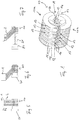
- the wave winding device preferably has a in FIG. 1 shown wire end receiving element 10.
- the wire end receiving element 10 is formed from two interconnected, preferably half-shells, segments 10a, 10b (not referred to below as "half shells") which form a wire insertion opening 11, 12 preferably formed as a slot.
- This opening referred to below as a slot, serves in the use of the wire end receiving element 10 according to the invention to receive a wire or a plurality of wires between the two half shells 10a, 10b.
- the complete wire end receiving element 10 is preferably shaped so that it fits into an enveloping cylinder (not shown) with a preferably circular base. All other cylindrical shapes, which can be referred to as general cylinders according to general mathematical principles are also conceivable as enveloping cylinder.
- Each of the half-shells 10a and 10b preferably has at least one groove or a plurality of grooves 13 formed between projections, which serve to receive a respective winding wire. If a winding wire is pushed into the slot 11, 12 and the wire end receiving element 10 is subsequently rotated about its longitudinal axis, the wire is wound on the wire end receiving element 10 while guided in one of the grooves 13. By performing several turns, any wire end length can be wound up on the wire end receiving element 10.
- the preferably provided grooves 13 are primarily used to wind a plurality of wires to be guided separately from each other and thereby keep separated. It is also conceivable, of course, that the wire end receiving element has no grooves at all, but is merely a block around which wire ends are wound.
- the accessible from the end face of the wire end receiving element 10 gap 14 between the two half-shells 10a and 10b is preferably formed so that it can be postponed to a later-still to be discussed winding element - preferably to form a positive connection.
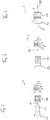
- the inventive wave winding device comprises on the one hand a wire outlet nozzle arrangement 1, from which one or a plurality of wires 2 are led out. So that the ends of the wires 2 can be wound onto the wire end receiving element 10 according to the invention, this is first (arrow P1 in FIG. 2 ) is mounted on a driven or driven winding element 20, in the example shown, it is pushed in the direction of arrow P1 on a winding element 20 provided on the winding mandrel 21. This connection is preferably done positively, so that the wire end receiving element 10 rotates with the winding element 20 with.
- the ends of the wires 2 which either come from the wire outlet nozzle arrangement 1 or are already protruding on an otherwise finished wave winding mat (not shown), are inserted into the preferably slot-shaped wire insertion opening 11, 12 (FIG. compare FIG. 1 ) of the wire end receiving element 10 is introduced. This is done by relative movement between wire ends 2 and wire end receiving element 10. This is in FIG. 3 indicated by the arrow P2. The way in which the relative movement takes place is left to the skilled person at this point, one possibility is to deliver the projecting wire ends 2 in the axial direction of the winding element 20 the same. Of course, other options are just as conceivable.
- the winding element 20 is driven about its longitudinal axis A (see arrow P3) and rotated so that the wire ends 2 are wound on the co-rotating wire end receiving element in the manner of a hair curler, FIG. 4 , This process continues until the desired length of the wire ends is wound on the wire end receiving element 10.
- winding element 20 and wire end receiving element 10 are again separated from each other, so that the wave winding mat can be supplied for further processing, FIG. 7 ,
- FIG. 2-7 shows the initial process before the actual wave wrap mat is created.
- the described method can likewise be used in order to wind up the corresponding wire ends in an already finished wave winding mat.
- the winding wire coming from the wire outlet nozzle arrangement 1 is severed and then wound up via the process shown with the winding element 20 and the wire end receiving element 10 located thereon.
Landscapes
- Engineering & Computer Science (AREA)
- Power Engineering (AREA)
- Manufacturing & Machinery (AREA)
- Manufacture Of Motors, Generators (AREA)
Priority Applications (1)
| Application Number | Priority Date | Filing Date | Title |
|---|---|---|---|
| EP18167306.2A EP3553927A1 (fr) | 2018-04-13 | 2018-04-13 | Dispositif d'enroulement ondulé et procédé d'enroulement ondulé |
Applications Claiming Priority (1)
| Application Number | Priority Date | Filing Date | Title |
|---|---|---|---|
| EP18167306.2A EP3553927A1 (fr) | 2018-04-13 | 2018-04-13 | Dispositif d'enroulement ondulé et procédé d'enroulement ondulé |
Publications (1)
| Publication Number | Publication Date |
|---|---|
| EP3553927A1 true EP3553927A1 (fr) | 2019-10-16 |
Family
ID=62002004
Family Applications (1)
| Application Number | Title | Priority Date | Filing Date |
|---|---|---|---|
| EP18167306.2A Withdrawn EP3553927A1 (fr) | 2018-04-13 | 2018-04-13 | Dispositif d'enroulement ondulé et procédé d'enroulement ondulé |
Country Status (1)
| Country | Link |
|---|---|
| EP (1) | EP3553927A1 (fr) |
Cited By (1)
| Publication number | Priority date | Publication date | Assignee | Title |
|---|---|---|---|---|
| DE102020207957A1 (de) | 2020-06-26 | 2021-12-30 | Volkswagen Aktiengesellschaft | Werkzeug und Verfahren zum automatisierten Abwickeln der Drahtenden von einem zur Herstellung einer Rotor- oder Statorwicklung verwendeten Drahtendenaufnahmeelement |
Citations (9)
| Publication number | Priority date | Publication date | Assignee | Title |
|---|---|---|---|---|
| US1787612A (en) * | 1928-07-11 | 1931-01-06 | Herbert S Bain | Coil winder |
| US2143315A (en) * | 1937-03-04 | 1939-01-10 | Hanson Bertrand | Winding apparatus |
| US2455355A (en) * | 1945-09-24 | 1948-12-07 | Edward E Combs | Method of making spherical coils for variometers |
| US3166104A (en) * | 1958-10-01 | 1965-01-19 | Gen Electric | Coil winding machine |
| DE2953092A1 (de) * | 1979-04-14 | 1980-12-11 | Veser F | Einrichtung bei wickelautomaten |
| EP2009768A2 (fr) * | 2007-06-29 | 2008-12-31 | Hitachi Ltd. | Machine électrique rotative ayant une bobine à enroulement ondulé avec conducteur croisé coudé, stator à enroulement distribué, et procédé et appareil de formation de celle-ci |
| JP2014045622A (ja) * | 2012-08-28 | 2014-03-13 | Aisin Seiki Co Ltd | 回転電機の巻線装置 |
| EP3182568A1 (fr) | 2015-12-18 | 2017-06-21 | Aumann GMBH | Dispositif de bobinages ondules |
| CN206790312U (zh) * | 2017-06-22 | 2017-12-22 | 宣红闻 | 一种可调节的电机绕线模具 |
-
2018
- 2018-04-13 EP EP18167306.2A patent/EP3553927A1/fr not_active Withdrawn
Patent Citations (9)
| Publication number | Priority date | Publication date | Assignee | Title |
|---|---|---|---|---|
| US1787612A (en) * | 1928-07-11 | 1931-01-06 | Herbert S Bain | Coil winder |
| US2143315A (en) * | 1937-03-04 | 1939-01-10 | Hanson Bertrand | Winding apparatus |
| US2455355A (en) * | 1945-09-24 | 1948-12-07 | Edward E Combs | Method of making spherical coils for variometers |
| US3166104A (en) * | 1958-10-01 | 1965-01-19 | Gen Electric | Coil winding machine |
| DE2953092A1 (de) * | 1979-04-14 | 1980-12-11 | Veser F | Einrichtung bei wickelautomaten |
| EP2009768A2 (fr) * | 2007-06-29 | 2008-12-31 | Hitachi Ltd. | Machine électrique rotative ayant une bobine à enroulement ondulé avec conducteur croisé coudé, stator à enroulement distribué, et procédé et appareil de formation de celle-ci |
| JP2014045622A (ja) * | 2012-08-28 | 2014-03-13 | Aisin Seiki Co Ltd | 回転電機の巻線装置 |
| EP3182568A1 (fr) | 2015-12-18 | 2017-06-21 | Aumann GMBH | Dispositif de bobinages ondules |
| CN206790312U (zh) * | 2017-06-22 | 2017-12-22 | 宣红闻 | 一种可调节的电机绕线模具 |
Cited By (1)
| Publication number | Priority date | Publication date | Assignee | Title |
|---|---|---|---|---|
| DE102020207957A1 (de) | 2020-06-26 | 2021-12-30 | Volkswagen Aktiengesellschaft | Werkzeug und Verfahren zum automatisierten Abwickeln der Drahtenden von einem zur Herstellung einer Rotor- oder Statorwicklung verwendeten Drahtendenaufnahmeelement |
Similar Documents
| Publication | Publication Date | Title |
|---|---|---|
| DE10113831B4 (de) | Leiterwicklung für dynamoelektrische Maschine | |
| EP2266192B1 (fr) | Rotor ou stator pour machines électriques et son procédé de fabrication | |
| EP3182568B2 (fr) | Dispositif de bobinages ondules | |
| DE2549833C2 (de) | Verfahren und Vorrichtung zur Zuführung einer Mehrzahl von Drähten | |
| EP2477315B1 (fr) | Système d'enroulement d'aiguille pour supports d'enroulement devant être enroulés, procédé d'enroulement de supports d'enroulement à enroulement réparti, stator intérieur, rotor extérieur et support d'enroulement pour moteurs électriques à enroulement réparti | |
| EP2309626B1 (fr) | Procédé de bobinage, notamment pour enrouler de bobines électriques | |
| WO2006008134A1 (fr) | Procede et systeme de production d'un enroulement statorique ou rotorique et enroulement statorique ou rotorique produit par ce procede et au moyen de ce systeme | |
| DE102018208407A1 (de) | Verfahren zur Herstellung von Formlitze, Verfahren zur Herstellung eines Elektromotors, sowie Verwendung von Formlitze | |
| EP4055674B1 (fr) | Procédé et dispositif de traitement d'un câble électrique | |
| EP4175139B1 (fr) | Dispositif et procédé de fabrication d'une flexion d'un enroulement ondulé pour un enroulement de bobine d'une machine électrique | |
| EP3804048B1 (fr) | Dispositif et procédé servant à usiner une extrémité d'un câble électrique | |
| AT522206B1 (de) | Verfahren zum Bereitstellen von Formstäben aus einem elektrischen Leiterdraht sowie entsprechende Formstäbe | |
| DE4300764C2 (de) | Verfahren und Vorrichtung zur Herstellung einer Wellenwicklung | |
| EP3544161B1 (fr) | Procédé et appareil d'introduction d'une matte d'enroulement ondulé dans le rotor ou dans le stator d'une machine électrique, en particulier dans un paquet de tôles statoriques | |
| DE102017213967A1 (de) | Vorrichtung zum Bearbeiten von Wicklungen | |
| EP2721724A2 (fr) | Procédé et dispositif d'enroulement d'un paquet de tôles de moteur électrique | |
| EP4311088A1 (fr) | Procédé et dispositif de fabrication d'une flexion multifilaire d'un enroulement d'arbre pour un enroulement de bobine d'une machine électrique | |
| EP3804105A1 (fr) | Procédé pour la fabrication d'un toron profilé, procédé pour la fabrication d'un moteur électrique ainsi qu'utilisation d'un toron profilé | |
| EP3531541A1 (fr) | Dispositif d'enroulement ondulé et procédé de fabrication d'un dispositif d'enroulement ondulé | |
| EP3429063A1 (fr) | Enroulement monocouche de support pour des machines électriques | |
| EP2845300B1 (fr) | Dispositif et procédé pour enrouler une bobine magnétique autour d'un paquet de tôles de moteur électrique | |
| EP3309938B1 (fr) | Procédé de bobinage des dents d'enroulement et dispositif d'aide à l'enroulement | |
| DE102021101678B3 (de) | Verfahren zum Bewickeln einer sich in einer Längsrichtung erstreckenden Zahnkette | |
| DE102023128256A1 (de) | Umformmaschine und Verfahren zur Spulenherstellung | |
| EP3937356A1 (fr) | Procédé et dispositif de fabrication d'un contour de fil pour un élément bobine d'un bobinage d'une machine électrique |
Legal Events
| Date | Code | Title | Description |
|---|---|---|---|
| PUAI | Public reference made under article 153(3) epc to a published international application that has entered the european phase |
Free format text: ORIGINAL CODE: 0009012 |
|
| AK | Designated contracting states |
Kind code of ref document: A1 Designated state(s): AL AT BE BG CH CY CZ DE DK EE ES FI FR GB GR HR HU IE IS IT LI LT LU LV MC MK MT NL NO PL PT RO RS SE SI SK SM TR |
|
| AX | Request for extension of the european patent |
Extension state: BA ME |
|
| STAA | Information on the status of an ep patent application or granted ep patent |
Free format text: STATUS: THE APPLICATION IS DEEMED TO BE WITHDRAWN |
|
| 18D | Application deemed to be withdrawn |
Effective date: 20200603 |