EP2009768A2 - Machine électrique rotative ayant une bobine à enroulement ondulé avec conducteur croisé coudé, stator à enroulement distribué, et procédé et appareil de formation de celle-ci - Google Patents
Machine électrique rotative ayant une bobine à enroulement ondulé avec conducteur croisé coudé, stator à enroulement distribué, et procédé et appareil de formation de celle-ci Download PDFInfo
- Publication number
- EP2009768A2 EP2009768A2 EP08252081A EP08252081A EP2009768A2 EP 2009768 A2 EP2009768 A2 EP 2009768A2 EP 08252081 A EP08252081 A EP 08252081A EP 08252081 A EP08252081 A EP 08252081A EP 2009768 A2 EP2009768 A2 EP 2009768A2
- Authority
- EP
- European Patent Office
- Prior art keywords
- coil
- wave winding
- stator
- conductor
- stator core
- Prior art date
- Legal status (The legal status is an assumption and is not a legal conclusion. Google has not performed a legal analysis and makes no representation as to the accuracy of the status listed.)
- Withdrawn
Links
Images










Classifications
-
- H—ELECTRICITY
- H02—GENERATION; CONVERSION OR DISTRIBUTION OF ELECTRIC POWER
- H02K—DYNAMO-ELECTRIC MACHINES
- H02K15/00—Processes or apparatus specially adapted for manufacturing, assembling, maintaining or repairing of dynamo-electric machines
- H02K15/04—Processes or apparatus specially adapted for manufacturing, assembling, maintaining or repairing of dynamo-electric machines of windings prior to their mounting into the machines
- H02K15/043—Processes or apparatus specially adapted for manufacturing, assembling, maintaining or repairing of dynamo-electric machines of windings prior to their mounting into the machines winding flat conductive wires or sheets
- H02K15/0432—Distributed windings
- H02K15/0433—Distributed windings of the wave winding type
-
- H—ELECTRICITY
- H02—GENERATION; CONVERSION OR DISTRIBUTION OF ELECTRIC POWER
- H02K—DYNAMO-ELECTRIC MACHINES
- H02K15/00—Processes or apparatus specially adapted for manufacturing, assembling, maintaining or repairing of dynamo-electric machines
- H02K15/06—Embedding prefabricated windings in the machines
- H02K15/062—Windings in slots; Salient pole windings
- H02K15/065—Windings consisting of complete sections, e.g. coils or waves
- H02K15/066—Windings consisting of complete sections, e.g. coils or waves inserted perpendicularly to the axis of the slots or inter-polar channels
-
- H—ELECTRICITY
- H02—GENERATION; CONVERSION OR DISTRIBUTION OF ELECTRIC POWER
- H02K—DYNAMO-ELECTRIC MACHINES
- H02K3/00—Details of windings
- H02K3/04—Windings characterised by the conductor shape, form or construction, e.g. with bar conductors
- H02K3/12—Windings characterised by the conductor shape, form or construction, e.g. with bar conductors arranged in slots
-
- H—ELECTRICITY
- H02—GENERATION; CONVERSION OR DISTRIBUTION OF ELECTRIC POWER
- H02K—DYNAMO-ELECTRIC MACHINES
- H02K15/00—Processes or apparatus specially adapted for manufacturing, assembling, maintaining or repairing of dynamo-electric machines
- H02K15/20—Shaping or compacting conductors or winding heads after the installation of the winding in the cores or machines; Applying fastening means on winding heads
- H02K15/22—Shaping or compacting conductors in slots or around salient poles
-
- Y—GENERAL TAGGING OF NEW TECHNOLOGICAL DEVELOPMENTS; GENERAL TAGGING OF CROSS-SECTIONAL TECHNOLOGIES SPANNING OVER SEVERAL SECTIONS OF THE IPC; TECHNICAL SUBJECTS COVERED BY FORMER USPC CROSS-REFERENCE ART COLLECTIONS [XRACs] AND DIGESTS
- Y10—TECHNICAL SUBJECTS COVERED BY FORMER USPC
- Y10T—TECHNICAL SUBJECTS COVERED BY FORMER US CLASSIFICATION
- Y10T29/00—Metal working
- Y10T29/49—Method of mechanical manufacture
- Y10T29/49002—Electrical device making
- Y10T29/49009—Dynamoelectric machine
-
- Y—GENERAL TAGGING OF NEW TECHNOLOGICAL DEVELOPMENTS; GENERAL TAGGING OF CROSS-SECTIONAL TECHNOLOGIES SPANNING OVER SEVERAL SECTIONS OF THE IPC; TECHNICAL SUBJECTS COVERED BY FORMER USPC CROSS-REFERENCE ART COLLECTIONS [XRACs] AND DIGESTS
- Y10—TECHNICAL SUBJECTS COVERED BY FORMER USPC
- Y10T—TECHNICAL SUBJECTS COVERED BY FORMER US CLASSIFICATION
- Y10T29/00—Metal working
- Y10T29/53—Means to assemble or disassemble
- Y10T29/5313—Means to assemble electrical device
- Y10T29/53143—Motor or generator
- Y10T29/53157—Means to stake wire to commutator or armature
Definitions
- the present invention relates to rotation electric machines such as motors and power generators, distributed winding stators and the method and apparatus for forming the same.
- Winding wire patterns of a stator include concentrated winding in which the coil is wound in a concentrated manner on every pole tooth, and distributed winding in which the coil is wound across a plurality of slots and having coils of different phases or of the same phase overlap at coil ends.
- the concentrated winding stator has smaller coil ends, which is advantageous in miniaturizing and improving the efficiency of a rotation electric machine.
- the distributed winding stator can approximate a rotating-field of the inner circumference of the stator to sine waves, and realize higher power than the concentratedwindingwith little noise.
- one method for achieving higher power in both winding patterns is to use a wire with a rectangular cross-section as the source wire of the coil and increase the coil lamination factor within the stator slots.
- the present invention is related to rotation electric machines having distributed winding stator coils formed of wires having a rectangular cross-section.
- Japanese patent No. 3823555 discloses a three-phase start coil in which the coil conductor of each phase is formed by wave winding, wherein the longitudinal side surface of flat rectangular conductors is opposed to the circumferential side of the stator slot.
- Japanese patent application laid-open publication No. 2004-350381 also discloses a wave winding coil, wherein the longitudinal side surface of flat rectangular conductors is opposed to the circumferential side of the stator slot.
- Japanese patent application laid-open publication No. 2001-161050 discloses bending flat rectangular conductors so that the surface of the longitudinal sides thereof opposes to the radial direction surface of the stator slots, inserting the bent conductors from the axial direction end face of the stator core into slots, and electrically connecting the open ends of the rectangular conductor portions protruded from the opposite end surface of the stator core so as to constitute a wave winding electric circuit.
- the rectangular conductors are substantially U-shaped, wherein the short side surfaces of the rectangular cross-section thereof are arranged in the same direction.
- the distributed winding stators adopting flat rectangular conductors have conductors arranged in the radial direction with a small number of partitions in the stator slots, whereas the distributed winding stators adopting square or rectangular conductors with the same or close vertical and horizontal lengths have parietal portions of the conductor constituting the coil ends protruded.
- Japanese patent application laid-open publication No. 2003-018778 discloses forming flat rectangular conductors into U-shapes and inserting the same to the slots of a stator core, bending both ends thereof, and connecting the ends with the ends of other adjacent U-shaped conductor segments to form a single electric conductor source wire to thereby form a stator winding. According to this arrangement, the stator core end surfaces are separated into a parietal region side and a connection side, wherein a large number of connections are formed on the connection side.
- the present invention aims at providing a coil shape of a distributed winding stator and the method of forming the same for obtaining a miniaturized rotation electric machine realizing high power and high effectiveness.
- the power output of the rotation electric machine is substantially determined by the number and shape of the slots of the stator core and the area within the slots occupied by the conductors. Therefore, the object of the invention is to realize higher lamination factor of conductors within the slots.
- the coil ends on both ends of the stator core must be minimized so as to realize a miniaturized rotation electric machine.
- a significant miniaturization effect is realized by shortening the ends for even one or two mm in the axial direction.
- the conductors disclosed in patent document 1 constitute wave winding coils in which the flat rectangular coil surfaces are bent without inverting the same, so a height corresponding at least to the longitudinal side of the rectangular cross-section is required.
- the present invention aims at reviewing such prior art bending and forming method of conductors and to achieve a formed coil type with smaller parietal regions.
- the conductor disclosed in patent document 1 is a segment coil type conductor in which the flat square wire is bent substantially into U-shapes, and two conductors are inserted into a single slot in the radial direction.
- the present invention aims at providing an arrangement in which the conductors arranged in a single slot is radially segmentalized, and the current density is reduced.
- patent document 4 discloses an arrangement with a large number of connections.
- the present invention aims at providing an arrangement having a small number of connections and reduced copper loss.
- the object of the present invention is to provide a coil shape and a method for forming the same having solved the three problems of the prior art mentioned above.
- the present invention provides a rotation electric machine having a stator, wherein a coil conductor having phases including a slot conductor portion composed of an outward conductor portion and a homeward conductor portion alternately inserted to respective slots of the core and a crossover conductor portion where a same side end portion of the outward conductor portion and the homeward conductor portion continuously constitute a coil end is subjected to wave winding, and wherein cranked portions are formed at substantial parietal regions of the crossover conductor portion.
- conductors having a rectangular cross-section with insulation coatings are used to constitute the coil, by which the lamination factor of conductors in slots are improved.
- the square conductors are arranged in a segmentalized manner in the radial direction in the stator slots, by which the current density is reduced.
- the rectangular conductor is formed into a wave winding shape composed of outward conductors and homeward conductors inserted alternately into respective slots of the core, by which the number of connections of the conductor terminals is cut down and the copper loss is reduced.
- the parietal portions on both ends of the wave winding rectangular conductors are displaced from each other for a distance corresponding to the total width of the source wire and are cranked within the range of the interval between adjacent stator slots, by which the coil ends are downsized.
- the portions of the formed coil corresponding to the stator slots are covered with insulation material and are assembled to all the slots of the stator, the wave winding coils are aligned at both coil ends of the stator, and the coil terminals are connected.
- the present invention enables to provide a distributed winding stator using coils formed by winding conductors having a rectangular cross-section in a continuous waveform, according to which the number of terminals of the coils is reduced compared to the prior art. Thereby, the reliability of production can be enhanced while taking advantages of the distributed winding stator having superior rotational characteristics.
- FIG. 1 shows a distributed winding stator 1 according to embodiment 1 of the present invention.
- FIG. 1A is a front view of the distributed winding stator 1 viewed from the side surface side of a stator core 2, wherein a circularity wave winding coil 7 having twelve coil source wires 3 formed in a circular wave form is assembled to a stator core 2, with the terminals 9 of the coil wires 3 connected.
- This arrangement enables to reduce the number of ends or number of connections, according to which the frequency of connection error is reduced and the yield is improved.
- FIG. 1B is a cross-sectional view showing in enlarged view the inner portion of a stator core slot 6 of the stator core 2.
- the stator core 2 is formed by press-drawing a rolled steel plate with a thickness of approximately 1 mm and laminating the same.
- the coil source wire 3 is a conductor wire with insulating coating, and in the present embodiment, a copper conductor is coated with polyamide-imide resin. Coil source wires 3 coated with insulating material are arranged inside the stator core slots 6 of the stator core 2. Since the coil wires 3 are coated with insulating material 4, the insulating property thereof is improved.
- the insulating material 4 is provided as a coating so as to insulate pinholes that may exist by some chance in the enamel coating of the coil source wire 3 and to prevent damage to the enamel coating during assembly to the stator core. Furthermore, by placing a wedge 5 to the stator core 2, it becomes possible to prevent the coil source wires 3 from escaping from the slot 6. If the overall cross-sectional areas of the coil source wires 3 in the stator core slot 6 are the same, the magnetic flux density will become higher as the number of wires increases.
- the coil wire 3 is a square wire with a substantially rectangular cross-section, wherein six square conductors are arranged along the axial direction within the stator core slots 6 of the stator core 2.
- the magnetic flux density is increased, the current density is reduced, and the efficiency of the rotation electric machine is improved according to the present example having six square conductors arranged compared to the case where two flat rectangular conductors are arranged along the axial direction.
- the portions of the coil source wires 3 coming out of the stator core that is, the portions of the coil source wires 3 crossed over between a stator core slot and another stator core slot are defined as crossover conductor portions 3d.
- FIG. 2 shows a distributed winding stator 1 having twelve circularity wave winding coils 7 assembled to a stator core 2 with 48 slots.
- FIG. 2A shows a plan view of a distributed winding stator 1 seen from the side of the terminal portion 9.
- the rotation electric machine of the present invention is a three-phase coil having a U-phase, a V-phase and a W-phase.
- the outer circumference side of the core in the slot is the starting end of winding of the circularity wave winding coils 7, and the inner circumference side of the core in the slot is the coil end of the circularity wave winding coils, wherein the circularity wave winding coils 7 are assembled to the stator core 2 in the following order: U1, V1, W1, U2, V2, W2 and so on.
- U1, V1, W1, U2, V2, W2 is assembled to the stator core 2 in the following order: U1, V1, W1, U2, V2, W2 and so on.
- FIG. 2B is a plan view of the distributed winding stator 1 seen from the side opposite from the terminal end portion. There is no connecting portion on the illustrated side, and twelve circularity wave winding coils 7 are assembled to the stator core 2 in the following order: U1, V1, W1, U2, V2, W2 and so on.
- the parietal region of each crossover conductor 3d also has a cranked portion 3c on the illustrated side opposite from the terminal end portion.
- FIGS. 3 through 10 the method for forming the distributed winding stator according to the present invention will be described with reference to FIGS. 3 through 10 .
- the number of coil source wires being wound is reduced and the number of slots in the stator core is also reduced in the drawings of FIGS. 3 through 10 .
- FIG. 3 illustrates a zonation wave winding jig 10 for winding the coil source wire 3 in a wave form.
- FIGS. 3A through 3C illustrate a state in which a single coil source wire 3 is set to the zonation wave winding jig 10, wherein FIG. 3A is a plan view of the zonation wave winding jig 10, FIG. 3B is a front view of the zonation wave winding jig 10 and FIG. 3C is a side view of the zonation wave winding jig 10.
- the coil source wire 3 can be set to the predetermined position correctly via locating pins 11 provided on the zonation wave winding jig 10.
- FIG. 4 illustrates a zonation wave winding jig 10 to which the coil source wire 3 is wound in a wave form.
- FIGS. 4A through 4C illustrate a state in which three coil wires 3 are wound around the zonation wave winding jig 10, wherein FIG. 4A is a plan view of the zonation wave winding jig 10, FIG. 4B is a front view of the zonation wave winding jig 10, and FIG. 4C is a side view of the zonation wave winding jig 10.
- the coil source wires 3 wound around the zonation wave winding jig 10 is wound in a wave form by rotating the zonation wave winding jig 10 and using the locating pins as guide, by which a zonation wave winding coil 8 having cranked portions 3c is formed.
- the side starting from the terminal on the starting end of the coil source wire 3 is defined as the outward conductor 3a, and the opposite side is defined as the homeward conductor 3b, as shown in FIGS. 4A and 4C .
- FIG. 5 illustrates a coil adhesion fairing jig 12 attached to the zonation wave winding jig 10.
- FIGS. 5A through 5C illustrate the state in which the coil adhesion fairing jig 12 is attached to the zonation wave winding jig 10 having a zonation wave winding coil 8 formed thereto, wherein FIG. 5A is a plan view of the zonation wave winding jig 10 and the adhesion fairing jig 12. The coil adhesion fairing jig 12 has chases 13 formed at positions for receiving the formed zonation wave winding coil 8.
- FIG. 5B is a front view of the zonation wave winding jig 10 and the adhesion fairing jig 12, and FIG.
- 5C is a side view of the zonation wave winding jig 10 and the coil adhesion fairing jig 12.
- the coil adhesion fairing jig 12 is designed so as not to interfere with the locating pins 11 attached to the zonation wave winding jig 10.
- FIG. 6 illustrates the formed zonation wave winding coil 8 attached to the coil adhesion fairing jig 12.
- FIGS. 6A through 6C illustrate a state in which the zonation wave winding jig is removed.
- FIG. 6A is a plan view of the adhesion fairing jig 12 and
- FIG. 6B is a front view of the adhesion fairing jig 12, wherein the shaped zonation wave winding coil 8 is received in the chases 13 of the adhesion fairing jig 12 without being parted.
- FIG. 6C is a side view of the adhesion fairing jig 12 and the disassembled and removed zonation wave winding jig.
- the zonation wave winding jig is composed of major jigs including a wave winding jig cored bar 100, wave winding jig side retention members 101 and wave winding jig side retention members 102.
- the wave winding jig can be disassembled and removed in the following order; the wave winding jig cored bar 100, the wave winding jig side retention members 101, and the wave winding jig side retention members 102.
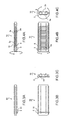
- FIG. 7 illustrates a state in which the zonation wave winding coil 8. is subjected to adhesion fairing using the coil adhesion fairing jig 12.
- FIG. 7A is a front view of the adhesion fairing jig 12
- FIG. 7B is a plan view of the adhesion fairing jig 12
- FIG. 7C is a side view of the adhesion fairing jig 12, wherein the adhesion fairing jigs 12 are moved in the direction of the arrow and put together so as to closely adhere the zonation wave winding coil 8.
- FIG. 8 illustrates the state after subjecting the zonation wave winding coil 8 to adhesion fairing.
- FIG. 8A is a front view of the adhesion fairing jig 12
- FIG. 8B is a plan view of the adhesion fairing jig 12
- FIG. 8C is a side view of the adhesion fairing jig 12, wherein by moving the adhesion fairing jig 12 in the direction of the arrow and opening the jig, an adhered zonation wave winding coil 8 is obtained.
- the coil since there is a clearance between the jig and the coil, and due to spring back of the shaped coil after opening the jig, the coil is not completely adhered.
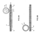
- FIG. 9 illustrates the process of forming the zonation wave winding coil 8 into a circularity wave winding coil 7.
- FIG. 9A shows the state in which the zonation wave winding coil 8 is started to be rolled up via a circularity wave winding jig 15.
- the adhesion fairing jig 12 used previously has extrusion pins 14, and the zonation wave winding jig 15 has chases 16.
- the circularity wave winding jig 15 is rotated and the extrusion pins 14 are pushed up sequentially to insert the zonation wave winding coil 8 sequentially into the chases 16 of the circularity wave winding jig 15.
- FIG. 9A shows the state in which the zonation wave winding coil 8 is started to be rolled up via a circularity wave winding jig 15.
- the adhesion fairing jig 12 used previously has extrusion pins 14, and the zonation wave winding jig 15 has chases 16.
- the circularity wave winding jig 15
- FIG. 9B shows a state in which the zonation wave winding coil is wound around the circularity wave winding jig 15 to form a circularity wave winding coil 7.
- the coil is wound around the circularity wave winding jig 15 and a circularity wave winding coil 7 is obtained.
- FIG. 10 illustrates a process for inserting the circularity wave winding coil 7 to the stator core 2.
- FIG. 10A illustrates a state in which the circularity wave winding jig 15 is set to the stator core 2.
- the circularity wave winding jig 15 to which the circularity wave winding coil 7 is wound around has extrusion pins 16 that move in the radial direction at positions corresponding to stator core slots 6.
- FIG. 10B illustrates a state in which the circularity wave winding coil 7 is inserted to the stator core slots 6 of the stator core 2.
- FIG. 10C illustrates a stator core 2 having the circularity wave winding coil 7 inserted thereto.
- FIG. 11 illustrates the parietal region 17 of the zonation wave winding coil 8 having the coil source wires wound around the zonation wave winding jig, wherein FIG. 11A is a perspective view, FIG. 11B is a side view, and FIG. 11C is a plan view seen from the side of the parietal region 17. As shown in FIG. 11B , the left and right sides of the wire below the parietal region 17 have different lengths, wherein L2 is longer than L1.
- the length of the outer circumference side must be longer, so that the side having the length L2 is positioned on the outer circumference side when forming the coil into a circularity coil.
- the substantial thickness of the zonation wave winding coil 8 has a size B1 that depends on the zonation wave winding jig.
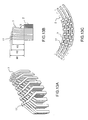
- FIG. 12 illustrates the parietal region 17 of the zonation wave winding coil 8 having been shaped by the coil adhesion fairing jig, wherein FIG. 12A is a perspective view, FIG. 12B is a side view, and FIG. 12C is a plan view seen from the side of the parietal region 17.
- FIG. 12C by shaping the coil using the coil adhesion fairing jig, the substantial thickness of the zonation wave winding coil 8 can be made as thin as dimension B2.
- FIG. 13 illustrates the parietal region 17 of the circularity wave winding coil 7 inserted to the stator core
- FIG. 13A is a perspective view
- FIG. 13B is a side view
- FIG. 13C is a plan view seen from the side of the parietal region 17.
- the two dot chain line of FIG. 13C shows the outline of the stator core 2.
- the heights of the parietal regions 17 from the end of the stator core 2 are varied, wherein the innermost circumference portion has a height H1, the intermediate portion has a height H2, and the outermost circumference portion has a height H3, the height being highest at H1 and lowest at H3.
- the circularitywave winding coil 7 is formed with an angle S, wherein the outermost circumference portion is most tilted. This arrangement prevents coil contact at the parietal regions, and therefore, the circularity wave winding coil 7 can be inserted to the stator core 2.
- FIG. 14 is a perspective view showing the state in which twelve coil wires 3 are wound around the zonation wave winding jig 10.
- the zonation wave winding jig 10 is composed of major jigs including the wave winding jig cored bar100, thewavewinding jig side retention members 101 and wave winding jig side retention members 102.
- the wave winding jig cored bar 100, the wave winding jig side retention members 101 and the wave winding jig side retention members 102 are sequentially removed in the named order so as to obtain twelve zonation wave winding coils.
- the locating pins 11 are arranged so that the wave winding coils can be inserted to predetermined positions of the stator core slots.
- FIG. 15 illustrates the state before and after inserting the twelve circularity wave winding coils 7 to the stator core 2 having forty-eight slots.
- FIG. 15A illustrates a state in which the circularity wave winding jig 15 is set to the stator core 2.
- the circularity wave winding jig 15 having the circularity wave winding coils 7 wound therearound has extrusion pins 16 that move in the radial direction arranged at positions facing the stator core slots 6. Further, insulating members 4 are inserted to the stator core slots 6.
- FIG. 15B illustrates a state in which the circularity wave winding coils 7 are inserted to the stator core slots 6 of the stator core 2.
- the circularitywave winding coils 7 are pushed outward via the circularity wave winding jig 15 and inserted to the stator core slots 6 of the stator core 2.
- the circularity wave winding jig By removing the circularity wave winding jig, it becomes possible to obtain a stator core 2 having forty-eight slots with six turns per slot.
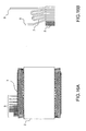
- FIG. 16A shows a view of the stator core 2 in which the circularity wave winding coil 7 is inserted, taken from the side portion of the stator core 2.
- FIG. 16B is a schematic cross-sectional view of the area near the terminal portion 9 showing the shape of the circularity wave winding coil 7 in the radial direction of the stator core 2. As for the distance from the end of the stator core 2 to the terminal portion 9, the ends arranged at the inner circumference side of the stator core 2 is formed longer.
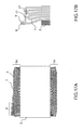
- FIG. 17 illustrates a state in which the terminal portion 9 at the inner circumference side of the stator core 2 is bent and formed, so that the terminal portion at the outer circumference side of the stator core 2 is connected with the terminal portion at the inner circumference side thereof.
- FIG. 17A shows a drawing seen from the side surface of the stator core 2
- FIG. 16B is a schematic cross-sectional view of the area near the terminal portion 9 showing the shape of the circularity wave winding coil 7 in the radial direction of the stator core 2 .
- the terminal portion 9 on the inner circumference side of the core having been bent and formed is crossed over the parietal region 17 and directly connected with the terminal portion 9 on the outer circumference side, and no other components are attached thereto.
- the preferred embodiment described herein has twelve circularity wave winding coils formed to constitute a continuous three-layer structure, wherein six conductors are arranged in a single slot.
- FIG. 18 is a view showing the process for assembling a circularity wave winding coil to a core according to another embodiment of the present invention, or embodiment 2.
- FIG. 18A illustrates a state in which a first layer of circularity wave winding coil 71 is assembled to a stator core 2
- FIG. 18B illustrates a state in which a second layer of circularity wave winding coil 72 is assembled to the stator core
- FIG. 18C illustrates a state in which a third layer of circularity wave winding coil 73 is assembled to the stator core, wherein the drawings are shown from the side opposite from the terminal portions.
- three layers of coils, each layer composed of twelve circularity wave winding coils are assembled to the core, with six conductors arranged in a single slot.
- FIG. 19 illustrates a state in which the terminals are connected.
- FIG. 19A illustrates a state in which circularity wave winding coils 71, 72 and 73 are assembled to the stator core 2 viewed from the side having terminal portions 9, and
- FIG. 19B is a schematic cross-sectional view of the terminal portions 9.
- One of the terminal portions 9 of the first layer of circularity wave winding coil 71 is connected to the second layer of circularity wave winding coil 72, and the other one of the terminal portions 9 of the first layer is connected to the terminal portion of the third layer of circularity wave winding coil 73.
- the other one of the terminal portions 9 of the second layer of circularity wave winding coil 72 is connected to the terminal portion of the third layer of circularity wave winding coil 73.
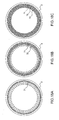
- FIG. 20 illustrates a state in which a circularity wave winding jig 15 having wound the circularity wave winding coil 7 is set to a stator core 2, wherein FIG. 20A is an axial cross-sectional view of the stator core 2, and FIG. 20B is a view showing the stator core 7 from the terminal side. As shown in FIG. 20A , rollers 19 are set to upper and lower ends of the stator core 7.
- FIG. 21 illustrates a state in which the upper and lower rollers 19 are moved in the outer side in the radial direction
- FIG. 21A is an axial cross-sectional view of the stator core 2
- FIG. 21B is a view showing the stator core 7 from the terminal side. Since the upper and lower rollers 19 are moved in the outer side in the radial direction, the circularity wave winding coil 7 near the area where the rollers 19 are pressed is inserted to the stator core slot 6 of the stator core 2.
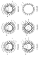
- FIG. 22 illustrates a view of the stator core 7 seen from the end surface side.
- FIGS. 22A, 22B and 22C in the named order, by rotating the stator core 2 and the circularity wave winding jig 15 with the roller 19 pressed against the circularity wave winding coil 7, the roller 19 rotates in a rolling motion, and the circularity wave winding coils 7 are sequentially inserted to the stator core slots 6 of the stator core 2.
- FIG. 22D illustrates a state in which the stator core 2 and the circularity wave winding jig 15 has gone around in a circle so that circularity wave winding coils 7 are inserted to all the slots.
- the roller 19 is moved to the radial inward direction, where the roller 19 and the circularity wave winding jig 15 is removed so as to obtain a stator core 2 having a circularity wave winding coil 7 inserted thereto as shown in FIG. 22F .
Landscapes
- Engineering & Computer Science (AREA)
- Power Engineering (AREA)
- Manufacturing & Machinery (AREA)
- Manufacture Of Motors, Generators (AREA)
- Windings For Motors And Generators (AREA)
Applications Claiming Priority (1)
| Application Number | Priority Date | Filing Date | Title |
|---|---|---|---|
| JP2007172098A JP2009011116A (ja) | 2007-06-29 | 2007-06-29 | 渡り導体部がクランク形状の波巻きコイルを備えた回転電機、分布巻固定子並びにそれらの成形方法及び成形装置 |
Publications (1)
| Publication Number | Publication Date |
|---|---|
| EP2009768A2 true EP2009768A2 (fr) | 2008-12-31 |
Family
ID=39811475
Family Applications (1)
| Application Number | Title | Priority Date | Filing Date |
|---|---|---|---|
| EP08252081A Withdrawn EP2009768A2 (fr) | 2007-06-29 | 2008-06-17 | Machine électrique rotative ayant une bobine à enroulement ondulé avec conducteur croisé coudé, stator à enroulement distribué, et procédé et appareil de formation de celle-ci |
Country Status (4)
| Country | Link |
|---|---|
| US (1) | US20090001841A1 (fr) |
| EP (1) | EP2009768A2 (fr) |
| JP (1) | JP2009011116A (fr) |
| CN (1) | CN101335471B (fr) |
Cited By (8)
| Publication number | Priority date | Publication date | Assignee | Title |
|---|---|---|---|---|
| FR2968858A1 (fr) * | 2010-12-10 | 2012-06-15 | Valeo Equip Electr Moteur | Bobinage d'une machine electrique tournante |
| FR3020219A1 (fr) * | 2014-04-17 | 2015-10-23 | Valeo Equip Electr Moteur | Procede de conformage de chignons d'un bobinage de machine electrique et stator correspondant |
| EP3057205A4 (fr) * | 2013-10-08 | 2017-05-31 | Mitsubishi Electric Corporation | Stator de machine électrique rotative |
| EP3109982A4 (fr) * | 2014-06-05 | 2017-06-21 | Aisin Aw Co., Ltd. | Procédé et dispositif de montage de stator |
| WO2017102892A3 (fr) * | 2015-12-15 | 2017-10-12 | Grob-Werke Gmbh & Co. Kg | Procédé et dispositif d'encastrement d'un paquet de fils dans une machine électrique |
| EP3553927A1 (fr) * | 2018-04-13 | 2019-10-16 | Aumann Espelkamp GmbH | Dispositif d'enroulement ondulé et procédé d'enroulement ondulé |
| FR3082371A1 (fr) * | 2018-06-11 | 2019-12-13 | Valeo Equipements Electriques Moteur | Stator de machine electrique tournante munie d'une confirguration de bobinage optimisee |
| CN114203405A (zh) * | 2020-09-02 | 2022-03-18 | 瑞昱半导体股份有限公司 | 电感装置 |
Families Citing this family (57)
| Publication number | Priority date | Publication date | Assignee | Title |
|---|---|---|---|---|
| JP5352979B2 (ja) * | 2007-09-20 | 2013-11-27 | 株式会社デンソー | 回転電機の固定子及びその製造方法 |
| JP5453770B2 (ja) | 2008-11-07 | 2014-03-26 | 株式会社デンソー | 回転電機の固定子およびその製造方法 |
| JP5131561B2 (ja) * | 2009-03-13 | 2013-01-30 | アイシン・エィ・ダブリュ株式会社 | コイル製造方法、コイル製造装置、及びコイル |
| JP5131560B2 (ja) * | 2009-03-13 | 2013-01-30 | アイシン・エィ・ダブリュ株式会社 | コイル製造方法及びコイル製造装置 |
| JP5471867B2 (ja) | 2009-07-17 | 2014-04-16 | 株式会社デンソー | 回転電機の固定子 |
| JP2011097723A (ja) * | 2009-10-29 | 2011-05-12 | Honda Motor Co Ltd | ステータの製造方法 |
| JP5621263B2 (ja) * | 2010-01-15 | 2014-11-12 | 株式会社デンソー | 固定子巻線の製造方法及びその製造装置 |
| JP5586969B2 (ja) * | 2010-01-21 | 2014-09-10 | 株式会社デンソー | 回転電機の固定子 |
| JP5471501B2 (ja) * | 2010-01-22 | 2014-04-16 | 株式会社デンソー | 固定子巻線の製造方法、その製造装置および回転電機 |
| US8294323B2 (en) * | 2010-02-08 | 2012-10-23 | GM Global Technology Operations LLC | Conducting wire for electric machine |
| JP5483111B2 (ja) * | 2010-10-15 | 2014-05-07 | 株式会社デンソー | 回転電機用固定子巻線の製造方法 |
| US9467010B2 (en) | 2011-11-17 | 2016-10-11 | Remy Technologies, L.L.C. | Method of winding a stator core with a continuous conductor having a rectangular cross-section and a stator core |
| US8789259B2 (en) | 2011-11-17 | 2014-07-29 | Remy Technologies, L.L.C. | Method of winding a stator core with a continuous conductor having a rectangular cross-section and a stator core |
| US8745847B2 (en) | 2011-11-17 | 2014-06-10 | Remy Technologies, L.L.C. | Method of P-forming a continuous conductor having a rectangular cross section and a stator including a stator winding formed from a P-formed conductor having a rectangular cross-section |
| US20130127286A1 (en) * | 2011-11-17 | 2013-05-23 | Remy Technologies, L.L.C. | Continuous stator winding having a rectangular cross-section and method |
| JP5821606B2 (ja) * | 2011-12-19 | 2015-11-24 | アイシン精機株式会社 | 回転電機のステータの製造方法 |
| JP2013165540A (ja) * | 2012-02-09 | 2013-08-22 | Toyota Motor Corp | コイルセグメント円環整列装置、及びステータ製造方法 |
| WO2013153594A1 (fr) * | 2012-04-09 | 2013-10-17 | トヨタ自動車株式会社 | Procédé de fabrication de stator et dispositif de formation de boîtier de bobine |
| US9641036B2 (en) | 2012-08-31 | 2017-05-02 | Mitsubishi Electric Corporation | Rotary electric machine |
| JP5680137B2 (ja) * | 2013-05-13 | 2015-03-04 | 日立オートモティブシステムズ株式会社 | 回転電機 |
| JP6080964B2 (ja) * | 2013-09-18 | 2017-02-15 | 三菱電機株式会社 | 回転電機の固定子 |
| JP6302698B2 (ja) * | 2014-02-14 | 2018-03-28 | 本田技研工業株式会社 | 回転電機ユニット |
| CN106605355B (zh) * | 2014-09-29 | 2019-03-08 | 日立汽车系统株式会社 | 旋转电机的定子以及具备该旋转电机的定子的旋转电机 |
| JP6369294B2 (ja) * | 2014-11-06 | 2018-08-08 | 株式会社デンソー | 回転電機の固定子 |
| WO2016104645A1 (fr) * | 2014-12-26 | 2016-06-30 | アイシン・エィ・ダブリュ株式会社 | Procédé de production de stator et bobine |
| CN107210658B (zh) * | 2015-02-13 | 2019-08-02 | 爱信艾达株式会社 | 定子的组装方法以及定子的组装装置 |
| JPWO2017056985A1 (ja) * | 2015-09-30 | 2018-05-10 | アイシン・エィ・ダブリュ株式会社 | ステータの組立方法 |
| DE102015120963A1 (de) * | 2015-12-02 | 2017-06-08 | Elmotec Statomat Vertriebs Gmbh | Verfahren und Vorrichtung zur Herstellung von Rotoren oder Spulen von elektrischen Maschinen |
| JP6513831B2 (ja) * | 2016-01-12 | 2019-05-15 | 日立オートモティブシステムズ株式会社 | 回転電機および車両 |
| JP6566262B2 (ja) | 2016-03-17 | 2019-08-28 | 株式会社デンソー | 回転電機の固定子 |
| US10523072B2 (en) * | 2016-06-15 | 2019-12-31 | Ford Global Technologies, Llc | Electric machine rotor |
| JP6458105B1 (ja) * | 2017-09-11 | 2019-01-23 | 株式会社小田原エンジニアリング | 回転電機の製造システム |
| CN109560639A (zh) * | 2017-09-27 | 2019-04-02 | 天津市松正电动汽车技术股份有限公司 | 一种方铜线电机定子结构 |
| FR3075502B1 (fr) * | 2017-12-20 | 2019-11-08 | Valeo Equipements Electriques Moteur | Stator pour machine electrique tournante |
| JP6591574B2 (ja) * | 2018-01-15 | 2019-10-16 | 本田技研工業株式会社 | 波巻コイルの保持装置、保持方法及び挿入方法 |
| CN108110973B (zh) * | 2018-01-31 | 2024-08-23 | 捷云智能装备(苏州)有限公司 | 发夹型导体组装机构及装配方法 |
| DE102018104838A1 (de) * | 2018-03-02 | 2019-09-05 | Aumann Espelkamp Gmbh | Verfahren und Vorrichtung zum Herstellen eines Stators mit einer Wicklung mit geschränkten Luftspulen |
| PL3544160T3 (pl) * | 2018-03-21 | 2020-11-02 | Aumann Espelkamp Gmbh | System do transportu falistych mat uzwojenia |
| JP7053419B2 (ja) * | 2018-09-14 | 2022-04-12 | トヨタ自動車株式会社 | 折り曲げ成形治具 |
| JP2021058076A (ja) * | 2019-04-24 | 2021-04-08 | 本田技研工業株式会社 | 導体成形装置及び波巻コイルの製造方法 |
| DE102019213474A1 (de) | 2019-09-05 | 2021-03-11 | Zf Friedrichshafen Ag | Spule mit Hairpinwicklung sowie Verfahren zu deren Herstellung |
| EP4084305A4 (fr) | 2020-01-22 | 2023-08-09 | Odawara Engineering Co., Ltd. | Procédé de torsion de segment de bobine, gabarit de torsion et dispositif de torsion |
| DE102020118925A1 (de) * | 2020-07-17 | 2022-01-20 | Schaeffler Technologies AG & Co. KG | Verfahren zur Herstellung einer Spulenwicklung und Wickelschablone |
| DE102020119303A1 (de) * | 2020-07-22 | 2022-01-27 | Schaeffler Technologies AG & Co. KG | Verfahren und Vorrichtung zum Einbringen isolierter Wickelpakete in Stator- oder Rotornuten, sowie Stator oder Rotor mit isolierten Wickelpaketen |
| FR3112905B1 (fr) * | 2020-07-23 | 2023-06-09 | Nidec Psa Emotors | Stator de machine électrique tournante |
| JP7351869B2 (ja) * | 2021-03-26 | 2023-09-27 | 本田技研工業株式会社 | ステータの製造方法 |
| DE102021119592A1 (de) | 2021-07-28 | 2022-08-25 | Schaeffler Technologies AG & Co. KG | Verfahren zur Herstellung einer optimierten Wickelkopfgeometrie und Spulenwicklung mit einer solchen Geometrie |
| JP7289894B2 (ja) * | 2021-11-11 | 2023-06-12 | 本田技研工業株式会社 | コイル成形装置及びコイル成形方法 |
| JP7289893B2 (ja) * | 2021-11-11 | 2023-06-12 | 本田技研工業株式会社 | コイル成形装置及びコイル成形方法 |
| JP7289892B2 (ja) * | 2021-11-11 | 2023-06-12 | 本田技研工業株式会社 | コイル成形装置及びコイル成形方法 |
| JP7320579B2 (ja) * | 2021-11-16 | 2023-08-03 | 本田技研工業株式会社 | コイル挿入ガイド装置 |
| DE102022130531A1 (de) * | 2022-11-18 | 2024-05-23 | Schaeffler Technologies AG & Co. KG | Linearmagazin und Kit-of-parts |
| HUE073391T2 (hu) * | 2022-12-20 | 2026-01-28 | Grob Gmbh & Co Kg | Eljárás és berendezés tekercsmatrica felhasználására elektromos gép alkatrészének gyártásában |
| CN116317400B (zh) * | 2023-02-07 | 2026-04-07 | 蔚来动力科技(合肥)有限公司 | 分布式波形绕组的成型方法和排线工装 |
| CN118737687A (zh) * | 2023-03-31 | 2024-10-01 | 本田技研工业株式会社 | 导体成型装置及导体成型方法 |
| EP4521616A1 (fr) * | 2023-09-08 | 2025-03-12 | Grob-Werke GmbH & Co. KG | Procédé et dispositif pour assembler un tapis de bobine sur un stator d'un moteur à rotor extérieur |
| DE102024113726A1 (de) * | 2024-05-16 | 2025-11-20 | Schaeffler Technologies AG & Co. KG | Wickelmatte, Verfahren und Vorrichtung zur Herstellung der Wickelmatte, Stator einer elektrischen Rotationsmaschine |
Citations (4)
| Publication number | Priority date | Publication date | Assignee | Title |
|---|---|---|---|---|
| JP2001161050A (ja) | 1999-11-30 | 2001-06-12 | Denso Corp | 液冷型車両用回転電機 |
| JP2003018778A (ja) | 2001-07-03 | 2003-01-17 | Toyota Motor Corp | 電動機 |
| JP2004350381A (ja) | 2003-05-21 | 2004-12-09 | Mitsubishi Electric Corp | 回転電機の固定子 |
| JP3823555B2 (ja) | 1998-08-24 | 2006-09-20 | 株式会社デンソー | 回転電機の多相波巻き巻線 |
Family Cites Families (9)
| Publication number | Priority date | Publication date | Assignee | Title |
|---|---|---|---|---|
| JP3952346B2 (ja) * | 1998-05-20 | 2007-08-01 | 株式会社デンソー | 回転電機及びその製造方法 |
| JP3407676B2 (ja) * | 1998-11-26 | 2003-05-19 | 株式会社デンソー | 車両用交流発電機の固定子およびそれを用いた車両用交流発電機 |
| JP3155535B1 (ja) * | 2000-01-27 | 2001-04-09 | 三菱電機株式会社 | 交流発電機 |
| JP3621635B2 (ja) * | 2000-08-10 | 2005-02-16 | 三菱電機株式会社 | 回転電機 |
| JP4310951B2 (ja) * | 2000-09-25 | 2009-08-12 | 株式会社デンソー | 車両用交流発電機の固定子の製造方法 |
| US6750581B2 (en) * | 2002-01-24 | 2004-06-15 | Visteon Global Technologies, Inc. | Automotive alternator stator assembly with rectangular continuous wire |
| JP2003235191A (ja) * | 2002-02-07 | 2003-08-22 | Toyota Motor Corp | 回転電機 |
| JP3982446B2 (ja) * | 2003-04-16 | 2007-09-26 | 株式会社日立製作所 | 回転電機の製造方法 |
| JP4452984B2 (ja) * | 2004-01-20 | 2010-04-21 | 株式会社デンソー | 回転電機の固定子巻線の製造方法 |
-
2007
- 2007-06-29 JP JP2007172098A patent/JP2009011116A/ja active Pending
-
2008
- 2008-06-17 EP EP08252081A patent/EP2009768A2/fr not_active Withdrawn
- 2008-06-24 CN CN200810131806.9A patent/CN101335471B/zh active Active
- 2008-06-26 US US12/213,910 patent/US20090001841A1/en not_active Abandoned
Patent Citations (4)
| Publication number | Priority date | Publication date | Assignee | Title |
|---|---|---|---|---|
| JP3823555B2 (ja) | 1998-08-24 | 2006-09-20 | 株式会社デンソー | 回転電機の多相波巻き巻線 |
| JP2001161050A (ja) | 1999-11-30 | 2001-06-12 | Denso Corp | 液冷型車両用回転電機 |
| JP2003018778A (ja) | 2001-07-03 | 2003-01-17 | Toyota Motor Corp | 電動機 |
| JP2004350381A (ja) | 2003-05-21 | 2004-12-09 | Mitsubishi Electric Corp | 回転電機の固定子 |
Cited By (14)
| Publication number | Priority date | Publication date | Assignee | Title |
|---|---|---|---|---|
| FR2968858A1 (fr) * | 2010-12-10 | 2012-06-15 | Valeo Equip Electr Moteur | Bobinage d'une machine electrique tournante |
| US9906085B2 (en) | 2013-10-08 | 2018-02-27 | Mitsubishi Electric Corporation | Stator for rotary electric machine |
| EP3057205A4 (fr) * | 2013-10-08 | 2017-05-31 | Mitsubishi Electric Corporation | Stator de machine électrique rotative |
| FR3020219A1 (fr) * | 2014-04-17 | 2015-10-23 | Valeo Equip Electr Moteur | Procede de conformage de chignons d'un bobinage de machine electrique et stator correspondant |
| US10084363B2 (en) | 2014-06-05 | 2018-09-25 | Aisin Aw Co., Ltd. | Stator assembly method and stator assembly apparatus |
| EP3109982A4 (fr) * | 2014-06-05 | 2017-06-21 | Aisin Aw Co., Ltd. | Procédé et dispositif de montage de stator |
| US10284060B2 (en) | 2014-06-05 | 2019-05-07 | Aisin Aw Co., Ltd. | Stator assembly method and stator assembly apparatus |
| US10910928B2 (en) | 2014-06-05 | 2021-02-02 | Aisin Aw Co., Ltd. | Stator assembly method and stator assembly apparatus |
| WO2017102892A3 (fr) * | 2015-12-15 | 2017-10-12 | Grob-Werke Gmbh & Co. Kg | Procédé et dispositif d'encastrement d'un paquet de fils dans une machine électrique |
| EP3391516B1 (fr) * | 2015-12-15 | 2021-04-28 | Grob-Werke GmbH & Co. KG | Procédé et dispositif d'encastrement d'un paquet de fils dans une machine électrique |
| US11108308B2 (en) | 2015-12-15 | 2021-08-31 | Grob-Werke Gmbh & Co. Kg | Apparatus for installing a wire package into an electrical machine |
| EP3553927A1 (fr) * | 2018-04-13 | 2019-10-16 | Aumann Espelkamp GmbH | Dispositif d'enroulement ondulé et procédé d'enroulement ondulé |
| FR3082371A1 (fr) * | 2018-06-11 | 2019-12-13 | Valeo Equipements Electriques Moteur | Stator de machine electrique tournante munie d'une confirguration de bobinage optimisee |
| CN114203405A (zh) * | 2020-09-02 | 2022-03-18 | 瑞昱半导体股份有限公司 | 电感装置 |
Also Published As
| Publication number | Publication date |
|---|---|
| CN101335471A (zh) | 2008-12-31 |
| US20090001841A1 (en) | 2009-01-01 |
| JP2009011116A (ja) | 2009-01-15 |
| CN101335471B (zh) | 2011-08-10 |
Similar Documents
| Publication | Publication Date | Title |
|---|---|---|
| EP2009768A2 (fr) | Machine électrique rotative ayant une bobine à enroulement ondulé avec conducteur croisé coudé, stator à enroulement distribué, et procédé et appareil de formation de celle-ci | |
| US7800273B2 (en) | AC electric rotating machine with multiphase stator coils | |
| CN110235342B (zh) | 用于电机的定子 | |
| EP1369979B1 (fr) | Procédé de fabrication d'enroulements statoriques d'une machine électrique tournante | |
| EP2219284B1 (fr) | Procédé de fabrication d'ensemble de bobines de machine dynamo-électrique | |
| US8963395B2 (en) | Motor core, stator, and method for manufacturing stator | |
| JP4577588B2 (ja) | 回転電機のコイル組立体製造方法 | |
| US12046967B2 (en) | Stator for an electric machine with a strip-like winding unit for a stator winding, and method for producing same | |
| JP5332347B2 (ja) | 回転電機のコイル組立体用のコイル線材 | |
| JP5487761B2 (ja) | 固定子コイルの製造方法 | |
| US20090015092A1 (en) | Method for winding the stator of an electric motor, and stator for an electric motor | |
| US20130127289A1 (en) | Conductor and rotating electrical machine | |
| US20130193798A1 (en) | Rotary electric machine | |
| US20130192057A1 (en) | Manufacturing method for coil unit | |
| US10164490B2 (en) | Rotary electric machine and manufacturing method therefor | |
| JP2000139048A (ja) | 回転電機及びその製造方法 | |
| JP2016152752A (ja) | 回転電機の固定子 | |
| KR20160145024A (ko) | 전기 기계 고정자 권선을 제조하는 방법 및 그에 대응하는 고정자 | |
| US8581467B2 (en) | Stator including a cage coil | |
| JPH1198740A (ja) | 回転電機のステータ及びコイルの製造方法 | |
| JP5298556B2 (ja) | ステータコイルの製造方法 | |
| JP4137864B2 (ja) | 回転電機のステータ | |
| JPWO2018185902A1 (ja) | 回転電機 | |
| JP2000069700A (ja) | 回転電機の多相波巻き巻線 | |
| US8122588B2 (en) | Method of manufacturing coil assembly of stator of electric rotating machine |
Legal Events
| Date | Code | Title | Description |
|---|---|---|---|
| PUAI | Public reference made under article 153(3) epc to a published international application that has entered the european phase |
Free format text: ORIGINAL CODE: 0009012 |
|
| 17P | Request for examination filed |
Effective date: 20080704 |
|
| AK | Designated contracting states |
Kind code of ref document: A2 Designated state(s): AT BE BG CH CY CZ DE DK EE ES FI FR GB GR HR HU IE IS IT LI LT LU LV MC MT NL NO PL PT RO SE SI SK TR |
|
| AX | Request for extension of the european patent |
Extension state: AL BA MK RS |
|
| RIC1 | Information provided on ipc code assigned before grant |
Ipc: H02K 15/06 20060101ALI20110915BHEP Ipc: H02K 3/12 20060101ALI20110915BHEP Ipc: H02K 15/04 20060101AFI20110915BHEP |
|
| STAA | Information on the status of an ep patent application or granted ep patent |
Free format text: STATUS: THE APPLICATION HAS BEEN WITHDRAWN |
|
| 18W | Application withdrawn |
Effective date: 20111208 |