EP3554330B1 - Écrou, charnière, siège de toilettes, raccord, système de fixation et dispositif - Google Patents
Écrou, charnière, siège de toilettes, raccord, système de fixation et dispositif Download PDFInfo
- Publication number
- EP3554330B1 EP3554330B1 EP17817736.6A EP17817736A EP3554330B1 EP 3554330 B1 EP3554330 B1 EP 3554330B1 EP 17817736 A EP17817736 A EP 17817736A EP 3554330 B1 EP3554330 B1 EP 3554330B1
- Authority
- EP
- European Patent Office
- Prior art keywords
- nut
- connector
- rib
- fastening system
- toilet
- Prior art date
- Legal status (The legal status is an assumption and is not a legal conclusion. Google has not performed a legal analysis and makes no representation as to the accuracy of the status listed.)
- Active
Links
Images


Classifications
-
- A—HUMAN NECESSITIES
- A47—FURNITURE; DOMESTIC ARTICLES OR APPLIANCES; COFFEE MILLS; SPICE MILLS; SUCTION CLEANERS IN GENERAL
- A47K—SANITARY EQUIPMENT; ACCESSORIES THEREFOR, e.g. TOILET ACCESSORIES
- A47K13/00—Seats or covers for all kinds of closets
- A47K13/24—Parts or details not covered in, or of interest apart from, groups A47K13/02 - A47K13/22
- A47K13/26—Mounting devices for seats or covers
-
- F—MECHANICAL ENGINEERING; LIGHTING; HEATING; WEAPONS; BLASTING
- F16—ENGINEERING ELEMENTS AND UNITS; GENERAL MEASURES FOR PRODUCING AND MAINTAINING EFFECTIVE FUNCTIONING OF MACHINES OR INSTALLATIONS; THERMAL INSULATION IN GENERAL
- F16B—DEVICES FOR FASTENING OR SECURING CONSTRUCTIONAL ELEMENTS OR MACHINE PARTS TOGETHER, e.g. NAILS, BOLTS, CIRCLIPS, CLAMPS, CLIPS OR WEDGES; JOINTS OR JOINTING
- F16B37/00—Nuts or like thread-engaging members
- F16B37/04—Devices for fastening nuts to surfaces, e.g. sheets, plates
- F16B37/041—Releasable devices
- F16B37/043—Releasable devices with snap action
-
- F—MECHANICAL ENGINEERING; LIGHTING; HEATING; WEAPONS; BLASTING
- F16—ENGINEERING ELEMENTS AND UNITS; GENERAL MEASURES FOR PRODUCING AND MAINTAINING EFFECTIVE FUNCTIONING OF MACHINES OR INSTALLATIONS; THERMAL INSULATION IN GENERAL
- F16B—DEVICES FOR FASTENING OR SECURING CONSTRUCTIONAL ELEMENTS OR MACHINE PARTS TOGETHER, e.g. NAILS, BOLTS, CIRCLIPS, CLAMPS, CLIPS OR WEDGES; JOINTS OR JOINTING
- F16B37/00—Nuts or like thread-engaging members
- F16B37/14—Cap nuts; Nut caps or bolt caps
Definitions
- the invention relates to a fastening system and also to a hinge for a toilet seat and/or toilet lid and a toilet seat and/or toilet lid.
- Toilet seats have hinges that connect to a toilet bowl through a fastening system.
- the hinges are fixedly spaced apart on the toilet seat.
- the distance between the fastening systems attached to the toilet bowl must therefore correspond to the distance between the hinges. This distance must be set precisely when assembling the toilet or when changing the toilet seat.
- the position of the fastening system should be adjustable so that the toilet seat is flush with the toilet bowl.
- Known fastening systems have a connector, which is also called a cage.
- the connector forms a coupling that, on the one hand, connects the hinge of the toilet seat and, on the other hand, a wall bracket with which the toilet bowl is attached to the bathroom wall.
- An example of such a connector is in DE 20 2007 117 328 U1 described, which also goes back to the applicant.
- the known connector has a receiving space for the head of a screw that is connected to the wall suspension.
- the connector accommodates a square nut in the receiving space, which is screwed to the hinge.
- This connector is divided into two parts and has a first receiving space for the head of the screw to be connected to the wall suspension and a second receiving space for a nut that is connected to the hinge. This improves the adjustability of the toilet seat.
- the mother will, as with the DE 20 2007 117 328 U1 , inserted laterally into the receiving space through a corresponding opening in the connector, which is not optimal for assembly.
- the document US 5,711,645 A discloses a toilet seat connecting bracket having a nut and an actuator attached thereto.
- the nut includes a plurality of half-cylinders connected together and having inner peripheral surfaces that together define a female screw portion whereby the nut can be screwed onto a bolt.
- the nut further includes engagement elements provided at one of its longitudinal ends to connect the plurality of half-cylinders together, the opposite longitudinal end having a connecting portion, for example a hinge element.
- the invention is based on the object of specifying a fastening system for fastening a toilet seat and/or toilet lid to a toilet bowl, through which the toilet seat and/or toilet lid is easy to assemble on the one hand and, on the other hand, allows sufficient movement for adjusting the toilet seat and/or toilet lid .
- the invention is also based on the object of providing a hinge for a toilet seat and/or toilet lid as well as a toilet seat and/or toilet lid, each with such a fastening system.
- the object is achieved with regard to the fastening system, the hinge and the toilet seat and/or toilet lid by the subjects of claims 1, 6 and 7.
- the invention is based on the idea of specifying a fastening system with a nut for fastening a toilet seat and/or toilet lid to a toilet bowl.
- the fastening system has a cylindrical connector that can be connected to the toilet bowl and forms a receiving space for the nut.
- the nut can be inserted into the receiving space and has a thread that can be connected to a hinge element of the toilet seat and/or toilet lid.
- An outer profile of the nut is adapted in such a way that, on the one hand, the nut can be inserted into the receiving space in a first assembly position in the axial direction along the longitudinal axis of the connector and, on the other hand, can be moved into a second holding position in the receiving space.
- the outer profile of the nut is adapted in such a way that in the holding position the outer profile at least partially engages behind an inner profile of the receiving space and forms an axial tension lock acting in the longitudinal direction of the connector.
- the nut has the advantage that it can assume different positions relative to the connector during assembly and in the final assembled state due to the correspondingly adapted outer profile.
- a first position ie in the assembly position
- the nut In a first position, ie in the assembly position, the nut can be inserted into the receiving space in the axial direction along the longitudinal axis of the connector.
- the nut In contrast to the prior art, the nut can be inserted into the connector from above.
- the ease of installation of the fastening system is significantly improved, because the connector can be mounted in the toilet bowl first and connected to the wall hanger.
- the nut is then inserted from above into the pre-assembled connector and screwed to the hinge, for example with a hinge bolt.
- the outer profile of the nut is adapted so that it can be moved into a second position, i.e. into a holding position, in the receiving space of the connector.
- the outer profile of the nut is further adapted so that it at least partially engages behind an inner profile of the receiving space of the connector in the holding position.
- the outer profile forms an axial tension protection acting in the longitudinal direction of the connector.
- the positioning of the nut in the connector allows, on the one hand, the assembly of the nut from above into the connector and, on the other hand, axial fixation in a direction opposite to the assembly direction when the nut is inserted.
- the outer profile can thus be moved from the assembly position in the circumferential direction of the nut into the holding position.
- the circumferential movement of the nut occurs with respect to the connector.
- the outer profile of the nut is adapted so that it can be rotated through a certain angle in the receiving space of the connector until the holding position is reached.
- the rotational movements move the nut from the assembly position into the holding position, so that the outer profile at least partially engages behind the inner profile of the receiving space of the connector.
- the torque required for the nut to rotate is applied when screwing in the hinge.
- the outer profile of the nut is adapted accordingly for this functionality.
- the outer profile is rib-shaped.
- the rib-shaped outer profile is adapted so that in the assembly position it can be aligned with the rib-shaped inner profile of the connector so that the nut can be inserted into the receiving space in the longitudinal direction of the connector.
- the rib-shaped outer profile and the rib-shaped inner profile are arranged at a gap in the assembly position.
- the rib-shaped outer profile is further adapted so that it can be rotated by a certain angle relative to the connector when inserted, i.e. in the receiving space. As a result, the outer profile is rotated from the assembly position (in the gap) into the holding position, in which the outer profile of the nut engages behind the inner profile of the connector.
- the rib-shaped outer profile of the nut is rotated under the rib-shaped inner profile of the connector.
- the rib-shaped inner profile of the connector thus forms a stop that secures the nut in the connector in the axial direction. In this position, the hinge can be screwed into the connector with a sufficiently high tightening force.
- the rib-shaped design of the outer profile has the further advantage that the surface pressure is distributed and a stable and robust axial tensile lock of the nut in the connector is possible.
- the width of a rib is preferably at least 2.8 mm, at least in the maximum cross section. This ensures that the rib forms a sufficiently large contact surface that engages behind the inner profile of the connector in the holding position. All ribs of the outer profile can be designed with this maximum width.
- the width of a rib can be at least 2.7 mm, at least 2.6 mm, at least 2.5 mm, at least 2.4 mm, at least 2.3 mm, at least 2.2 mm, at least 2, at least in the maximum cross section. 1 mm, at least 2.0 mm.
- the side surfaces of a rib extending in the axial direction form an angle of at most 16°.
- an outer profile of the nut has a projection as an anti-rotation device for fixing the nut in the receiving space in the circumferential direction of the connector.
- the projection projects in the axial direction over a lower edge of the nut and can be brought into engagement with a corresponding recess in the bottom of the receiving space.
- the anti-twist device extending in the assembly direction has the advantage that the nut can be secured in the connector in a simple manner.
- the invention further relates to a hinge element for a seat ring of a toilet and a seat ring for a toilet.
- the term “toilet” refers to a sanitary facility for receiving human body waste, which is usually made of ceramic and is usually installed or attached to the floor or wall.
- the toilet seat fastener can also be used to pivotably attach a lid to or on a toilet.
- the seat ring and lid are attached to a toilet with two hinges.
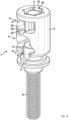
- Fig. 1 shows a nut according to an embodiment of the invention, which is designed to fasten a toilet seat and / or toilet lid. It is understood that the nut can only be used with a toilet seat or only with a toilet lid.
- the toilet seat and the toilet lid usually form a unit.
- the toilet seat and/or toilet lid are hereinafter referred to as a toilet seat unit.
- the toilet seat unit and the nut form a marketable sales unit that is offered together in stores. Accordingly, the toilet seat unit and the nut are disclosed as a combination.
- the connector according to Fig. 5 is usually offered in conjunction with a wall mounting system for a toilet bowl. For final assembly, the nut and toilet seat unit are brought together with the connector or wall mounting system.
- FIG. 1 to 7 a first embodiment of the nut 3 and the connector 2 is shown.
- the Figures 8 to 11 relate to a second exemplary embodiment, in which the outer profile 30 of the nut 3 and the inner profile 31 of the connector 2 differ from the first exemplary embodiment.
- Both exemplary embodiments are based on the same basic principle, according to which the nut 3 can be inserted into the connector 2 from above due to the adapted outer profile 30 and can be rotated to a limited extent in the connector 2.
- the nut 3 has a thread 26 which is arranged and held in a plastic body 14.
- the thread 26 is connected to the hinge of the toilet seat unit (see Fig. 11 ).
- a hinge element in particular a hinge bolt, is screwed into the thread 26.
- the connector 2 will be described in more detail below.
- the connector 2 according to Fig. 5 has a first (lower) receiving space 4 for the head 8 of a fastening screw 9, for example in Fig. 8 is shown.
- the screw 9 serves to connect the connector 2 to a counterpart of the wall mounting system (not shown).
- the connector 2 has a second (upper) receiving space 5, into which the nut 3 according to Fig. 1 introduced during assembly.
- the two receiving spaces 4, 5 and the insertion opening 20 are arranged coaxially in the longitudinal direction of the connector 2.
- the two receiving spaces 4, 5 are separated from each other by a floor 23, which can also be referred to as a partition.
- a floor 23 which can also be referred to as a partition.
- a central opening 24 is formed in the base 23, which is coaxial with the insertion opening 20 and serves to provide access for an Allen key with which the screw 9 can be tightened.
- This arrangement is in the Figures 8 , 9 shown.
- the second, upper receiving space 5 is delimited to the outside by an end wall 19 which extends parallel to the floor 23.
- the insertion opening 20 and the inner profile 31 are formed in the end wall 19.
- the first, lower receiving space 4 is designed essentially identically in both exemplary embodiments.
- the receiving space 4 is delimited by a lower end wall 6, which extends parallel to the floor 23 and has a slot 7 for receiving the screw head 8 (see Fig. 8 ).
- the slot 7 is delimited by 2 snap lugs 12, which hold the head 8 in the receiving space 4.
- the inner profile 31 forms the inner circumference of the insertion opening 20.
- the inner profile 31 includes a plurality of mounting openings 39 which are formed between holding projections 40.
- the holding projections 40 and the mounting openings 39 are arranged alternately distributed around the circumference.
- the holding projections 40 are rib-shaped.
- the shape of the holding projections 40 essentially corresponds to the shape of the ribs 16, 16a, 16b of the nut 3, which are explained in more detail below.
- the inner profile 31 also has an insertion edge 35, with a further insertion edge 35 being arranged diametrically opposite.
- the two insertion edges 35 are symmetrical.
- the insertion edges 35 are each wider than the holding projections 40 or the mounting openings 39.
- the insertion edges 35 cooperate with the locking springs 17 of the nut 3.
- the holding projections 40 and in the insertion edge 35 each form undercuts 21, as in Fig. 6 shown.
- the undercuts 21 are gripped behind by the outer profile 30 of the nut 3 and thus block axial movement of the nut, which is thereby held firmly in the receiving space 5.
- a recess 22 is formed in the bottom 23 and extends radially.
- the recess 22 can also be referred to as a rotation locking groove.
- Stop surface 41 delimits the recess 22 and serves as a stop in use and thus as an anti-rotation device for the nut 3.
- the width of the recess 22, i.e. the distance between the opposing stop surfaces 41, is dimensioned such that a limited rotation of the nut 3 in the receiving space is possible .
- the mother 3 will be explained in detail below.
- the outer profile 30 of the nut 3 extends in the circumferential direction around the nut 3 and in the axial and radial directions with respect to the nut 3.
- the outer profile 30 of the nut 3 and the inner profile 31 of the connector 2 are adapted to one another.
- the outer profile 30 is adapted so that the nut 3 can be inserted into the receiving space 5 through the insertion opening 20 in the axial direction, ie along the central axis of the connector 2.
- the intended position of the nut 3 is referred to as the first assembly position.
- the outer profile 30 is further adapted so that the nut 3 in the receiving space 5 can be rotated in the circumferential direction of the nut 3. Due to the rotation, the outer profile 30 at least partially engages behind the inner profile 31.
- This position of the nut 3 is referred to as the second holding position. In the holding position, the outer profile 30 forms an axial tension lock acting in the longitudinal direction of the connector 2, through which the nut 3 is held firmly in the connector 2.
- the outer profile 30 has a plurality of ribs 16, 16a, 16b, which are arranged distributed around the circumference of the nut 3.
- the ribs 16, 16a, 16b protrude radially outwards from the nut 3 and extend in the axial direction, ie parallel to the longitudinal axis of the nut 3.
- the longitudinal axis of the nut 3 can also be referred to as the central axis.
- the nut 3 has ten ribs 16, 16a, 16b, which are arranged symmetrically distributed around the circumference of the nut 3.
- the inner profile 31 of the connector 2 has a corresponding number of mounting openings 39 (specifically ten mounting openings 39), which are arranged distributed over the circumference of the insertion opening 20.
- the dimensions and positions of the ribs 16, 16a, 16b are adapted to the mounting openings 39.
- mother 3 has fewer than ten ribs.
- the maximum number of ribs 16, 16a, 16b of the nut 3 corresponds to the number of mounting openings 39 of the connector 2.
- the nut 3 can have fewer ribs 16, 16a, 16b than mounting openings 39 of the connector 2.
- the upper end faces of the ribs 16, 16a, 16b are designed as stop surfaces 37, which in the holding position rest on the inner profile 31 of the connector, specifically on the underside of the holding projections 40, and block axial movement of the nut 3.
- the stop surfaces 37 are arranged in one and the same plane, which extends perpendicular to the longitudinal axis of the nut 30. This ensures that the ribs 16, 16a, 16b can be moved under the holding projections 40 of the inner profile 31 by the rotary movement.
- the lower end faces of the ribs 16, 16a, 16b are also arranged in one and the same plane, which runs perpendicular to the central axis or longitudinal axis of the nut 3.
- the lower edge 33 is arranged in this plane.
- the nut 3 rests on the underside of the ribs 16, 16b in the receiving space 5.
- the ribs 16, 16a have a first rib 16a, which is designed as an anti-rotation device.
- the first rib 16a protrudes downwards and forms an extension or projection 18 (anti-rotation device).
- the lead 18 is in axial direction over the lower edge 33 of the nut 3, as in Fig. 1 to recognize.
- the projection 18 engages in the associated recess 22 in the bottom 23 of the connector 2.
- the recess 22 can also be referred to as a rotation locking groove.
- the intervention state is in the Figures 8 , 9 shown using the second exemplary embodiment.
- Two first ribs 16a are designed as anti-rotation devices, which are arranged diametrically opposite one another.
- the recess 22 in the bottom 23 of the connector 2 is designed accordingly and extends on both sides of the central opening 24.
- the nut 3 has detent springs 17, in particular two detent springs 17, arranged diametrically opposite one another.
- the detent springs 17 are attached to the lower edge 33 of the nut 3 with a foot 38 on the nut 3 and protrude obliquely upwards against the assembly direction.
- the free end 34 of the detent springs 17 is arranged radially further out than the foot 38 and forms the maximum radial position of the detent spring 17.
- the detent spring 17 is movable in the radial direction.
- the detent springs 17 are pressed radially inwards by the insertion edge 35 at the insertion opening 20 of the connector 2.
- the locking springs 17 snap into place Fig. 3 shown rest position, so that the free ends 34 move radially outwards.
- the locking springs 17 engage behind the inner profile 31 and lie on the underside of the inner profile 31 in the area of the insertion edges 35. The nut 3 is axially secured and can no longer accidentally slip out of the connector 2 during assembly.
- the arrangement of the locking springs 17 and the associated insertion edges 35 has the further advantage that the nut 3 is inserted into the insertion opening 20 in a predetermined position. This is because the insertion edge 30 is wider than the mounting openings 39. This ensures that the first two ribs 16a (anti-rotation device) are correctly aligned and engage in the associated recesses 22 in the base 23. It goes without saying that the mother 3 can have a single first rib 16a as an anti-rotation device.
- the nut has a collar 15 which protrudes upwards in a ring shape over the ribs 16, 16a, 16b.
- the collar is coaxial with the thread 26 ( Fig. 2 ).
- the outer diameter of the collar 15 is dimensioned such that it can be arranged with play in the insertion opening 20, ie between the retaining projections 40 of the connector 2.
- the ribs 16, 16a, 16b are dimensioned and positioned as follows (see Fig. Figures 2, 3 , 4 ). Except for the height, the ribs 16, 16a, 16b are dimensioned accordingly.
- the first ribs 16a are higher than the second ribs 16b to prevent rotation.
- the detent springs 17 are also dimensioned accordingly.
- the height A of a rib 16, 16b can be smaller, for example 10.8 mm, 10.7 mm, etc.
- Height B of a rib 16, 16b can be smaller, for example 10.8 mm, 10.7 mm, etc.
- the maximum width is at the outer edge of the rib 16.
- the maximum width C can be smaller than 2.8 mm.
- a detent spring 17 replaces a rib 16.
- the ribs 16, 16a, 16b widen as the distance from the central axis of the nut 3 increases.
- the number of ribs 16, 16a, 16b of the nut 3 corresponds to the number of mounting openings 39 or holding projections 40 of the connector 2.
- the angles g1, g2 between adjacent mounting openings 39 correspond to the angles G1, G2 between adjacent ribs 16, 16a, 16b.
- the smaller inner diameter d2 of the inner profile 31, for example between the insertion edges 35 or between two diametrically opposite holding projections 40, is d2 approx. 17 mm.
- the height a of the receiving space 5, specifically the distance between the floor 23 next to the recess 22 and the underside of the holding projections or generally the undercut 21, is a approx. 11 mm.
- the second exemplary embodiment in FIGS. 8 to 11 differs from the first exemplary embodiment Figures 1 to 7 on the one hand, in that the outer profile 30 of the nut 3 has ribs and locking springs which are arranged alternately on the circumference of the nut 3.
- the inner profile 31 of the insertion opening 20 of the connector 2 is designed accordingly and has a plurality of insertion edges and mounting openings distributed alternately around the circumference.
- the basic principle according to which the nut 3 can be inserted from above into the receiving space 5 of the connector 2 (first assembly position) corresponds to the basic principle of the nut Fig. 1 .
- the assembly is as shown in the illustration Fig. 11 clarified, in practice the nut 3 is usually screwed to a hinge bolt, which in turn is connected to the hinge joint of the toilet seat unit, for example by a snap lock.
- the principle is the same.
- the connector 2 with the screw 9 in the lower receiving space 4 is screwed to a wall fastening system, not shown, the screw 9 being screwed in from above with a hexagonal wrench through the insertion opening 20 and the central opening 24.
- the connector 2 is now mounted in the toilet bowl.
- the nut 3 with the hinge or hinge element 29 is inserted into the connector 2 in the assembly position, as shown by the directional arrow.
- the outer profile 30 of the nut and the inner profile 31 of the insertion opening 20 or the connector 2 are aligned so that the nut 3 fits through the insertion opening 20.
- the ribs 16, 16a, 16b are aligned with the mounting openings 39, so that the ribs 16, 16a, 16b can be moved through the respective mounting openings 39.
- the nut 3 as shown in both exemplary embodiments, is equipped with locking springs 17, these are also aligned with the associated inner profile 31, specifically with the insertion edges 35. In the first exemplary embodiment, this has the advantage that the first rib 16a with the anti-twist device is correct is positioned.
- the projection 18 of the first rib 16a engages in the recess 22 in the bottom 23 of the upper receiving space.
- the remaining second ribs 16b lie on the floor 23 next to the recess 22.
- the Stop surface 37 of the ribs 16, 16a, 16b is arranged slightly lower than the underside or undercut 21 of the inner profile 31.
- the nut 3 or the thread 26 of the nut 3 is then connected to the hinge element 23, in particular the hinge bolt. It is also possible, as in Fig. 11 shown, first to connect the nut 3 to the hinge bolt or hinge element 29 and then to insert the nut 3 into the connector 2.
- the nut 3 Due to the torque introduced via the hinge pin, the nut 3 is rotated in the circumferential direction in the receiving space until the projection 18 abuts one of the stop surfaces 41 of the recess 22. This achieves two effects.
- the ribs 16, 16a, 16b are moved under the retaining projections 40 of the end wall 19 by the rotational movement of the nut 3. This means that the mother 3 is axially secured in the receiving space 5.
- the rotational movement of the nut 3 is then blocked by the stop surface 41, so that the hinge pin is screwed further into the nut 3 and this is clamped with the connector.
- the toilet seat unit can be adjusted before the hinge bolt is tightened.
- the hinge of the toilet seat unit is perfectly connected to the bowl, making assembly quick and easy.
- Toilet seat fastener 1 shown is used to fasten a seat ring and / or a lid on a toilet, not shown.
- the toilet seat fastener 1 has a connector 2 and a nut 3.
- the connector 2 is a cylindrical plastic part with two cavities 4, 5 that are open laterally and on the end faces of the connector 2.
- the connector 2 has an inwardly projecting end wall 6 with a slot 7 on, which is open on the side on which the associated cavity 4 is also open, which is referred to below as the lower cavity 4.
- a special screw head 8 of a screw 9 can be inserted into the slot 7 radially from one side.
- special screw head it is meant that the screw head 8 is cylindrical and has a hexagon socket 10 in one end face as a tool seat for turning the screw 9 with a screw (not shown).
- Allen key and two parallel grooves 11 on the circumference.
- the parallel grooves 11 are arranged opposite one another and have mutually parallel groove bottoms.
- the end wall 6 of the connector 2 engages in the parallel grooves 11 of the screw head 8, so that the screw 9 is connected to the connector 2 in a coaxial, rotationally and axially fixed manner.
- the screw head 8 with the parallel grooves 11 and the end wall 6 of the connector 2 with the slot 7 can also be viewed as a device for connecting the screw 9 to the connector 2.
- the end wall 6 of the connector 2 has inwardly extending snap lugs 12 which hold the screw head 8 in the slot 7.
- the connector 2 can be attached to the toilet (not shown) using the screw 9.
- Nut 3 shown as an individual part in an axial section, has a conventional hexagonal nut 13 made of metal, which is encapsulated with a plastic body 14.
- the plastic body 14 is part of the nut 3 and has a tubular, axially short collar 15 coaxial with the hexagon nut 13 and ribs 16 projecting outwards in a star shape.
- spring tongues which are referred to below as locking elements 17, protrude obliquely outwards from the nut 3 in the direction of the collar 15 at an acute angle to an axis of the nut 3.
- the spring tongues merge in one piece into the plastic body 14 of the nut 3.
- the connector 2 has a perforated disk-shaped end wall 19 with a center hole which has a multi-groove profile that is complementary to the ribs 16 of the nut 3.
- the center hole of the end wall 19 at the upper end of the connector 2 will be referred to below as the opening 20 of the adjacent cavity 5 of the connector 2, this cavity 5 being referred to below as the upper cavity 5.
- the opening 20 of the upper cavity 5 corresponds geometrically with the nut 3.
- the nut 3 can be inserted axially to the screw 9 into the upper cavity 5 of the Connector 2 are introduced, with the locking elements 17 engaging on an underside of the end wall 19 facing the upper cavity 5, so that the nut 3 is held axially fixed in the cavity 5.
- the underside of the end wall 19 forms an undercut 21, which the locking elements 17 engage behind.
- the connector 2 of the toilet seat fastener 1 connects the nut 3 to the screw 9 on the same axis and in an axially fixed manner.
- “Axially fixed” means a tensile and pressure-resistant connection of the nut 3 to the screw 9.
- the locking elements 17 and the end wall 19, which engage behind the locking elements 17, form a locking device 17, 19, which engages when the nut 3 is inserted into the upper cavity 5 of the connector 2 and holds the nut 3 in the upper cavity 5.
- the upper cavity 5 has no lateral opening, or the lateral opening is so small that no nut can be inserted laterally.
- an Allen key (not shown) can be used to turn and tighten the screw 9 on the hexagon socket 10 of its screw head 3.
- the ribs 16 are arranged and shaped on the nut 3 in such a way that the nut 3 can only be inserted into the upper cavity 5 of the connector 2 in a specific angular position rotated by 180 ° through the complementary multi-groove profile of the opening 20.
- the two anti-rotation lugs 18 are located in the same axial plane as an anti-rotation groove 22 in the intermediate wall 23 between the two cavities 4, 5 of the connector 2.
- the anti-rotation lugs 18 pass through the opening 20 in the end wall 19 when the nut 3 is inserted upper end of the connector 2 into the upper cavity 5 into the anti-rotation groove 22 in the intermediate wall 23, so that the nut 3 is accommodated in the upper cavity 5 of the connector 2 in a rotationally fixed manner by positive locking.
- Other rotation locks of the nut 3 in the upper cavity 5 of the connector 2 are not excluded.
- the connector 2 connects the nut 3 to the screw 9 in a rotationally fixed manner.
- the collar 15 of the nut 3 projects into the opening 20 of the end wall 19 when the nut 3 is inserted into the upper cavity 5 of the connector 2.
- the collar 15 has play in the opening 20, so that the nut 3 is accommodated in the upper cavity of the connector 2 in a radially movable manner. This allows a seat ring and/or lid, which is attached to a toilet using the connector 2, to be aligned with the toilet.
- FIG 15 is a right-angled bolt with a thread 25 on one leg screwed into a nut thread 26 of the nut 3.
- a seat ring 27 and a cover 28 are pivotally mounted on another leg of the angled bolt.
- the angled bolt forms a hinge or hinge element 29 for the seat ring 27 and the cover 28, via which the seat ring 27 and the cover 28 are connected to the connector 2 of the toilet seat fastener 1 by means of the nut 3 and via the connector 2 and the screw 9 to the one not shown Toilet can be attached.
- the hinge element 29 is fastened to the seat ring 27 and the cover 28 by inserting and snapping the nut 3, into which the hinge element 29 is screwed, through the opening 20 into the upper cavity 5 of the connector 2.
- the nut 3 can also be Without inserting the hinge element 29 through the opening 20 into the upper cavity 5 of the connector 2 and snapping it into place.
Landscapes
- Health & Medical Sciences (AREA)
- Public Health (AREA)
- Toilet Supplies (AREA)
Claims (7)
- Système de fixation (1) destiné à la fixation d'un siège de toilettes et/ou d'un couvercle de toilettes sur une cuvette de toilettes, qui comporte un raccord cylindrique (2) et un écrou (3), sachant que le raccord cylindrique (2) peut être raccordé à la cuvette de toilettes et forme un espace de logement (5) pour l'écrou (3) et comporte en plus un profil intérieur (31), qui est constitué en forme de nervure dans la zone d'une ouverture d'introduction (20) pour l'écrou (3) dans l'espace de logement (5) et comporte des bords d'introduction (35) disposés diamétralement opposés, chacun formant une dépouille (21) pour un ressort d'enclenchement (17) de l'écrou (3), sachant que l'écrou (3) peut être introduit dans l'espace de logement (5) et comporte un filetage (26), qui peut être raccordé à un élément de charnière (29) du siège de toilettes et/ou du couvercle de toilettes, sachant qu'un profil extérieur (30) de l'écrou (3), qui est en corrélation avec le profil intérieur (31) du raccord (2) comporte plusieurs nervures axiales (16, 16a, 16b), comprenant des premières et deuxièmes nervures, qui sont disposées réparties à la périphérie de l'écrou (3) et qui sont orientées avec le profil intérieur en forme de nervure (31) du raccord (2) de telle sorte que l'écrou (3) peut être introduit en direction axiale, c.à d. le long de l'axe médian du raccord (2) à travers l'ouverture d'introduction (20) dans l'espace de logement (5) et l'écrou (3) comporte des ressorts d'enclenchement (17) disposés diamétralement opposés, qui coopèrent avec les bords d'introduction (35) et qui peuvent être déplacés radialement vers l'intérieur et radialement vers l'extérieur et sachant qu'au moins une deuxième nervure (16b) est constituée en tant que sécurisation de traction pour la fixation de l'écrou (3) dans l'espace de logement (5) en direction longitudinale du raccord (2), qui lors d'une rotation du profil extérieur (30) de l'écrou (3) d'une position de montage en une position de maintien saisit par l'arrière au moins en partie le profil intérieur en forme de nervure (31) du raccord (2) et sachant que le profil extérieur (30) de l'écrou (3) comporte une ou deux premières nervures (16a) disposées diamétralement opposées avec une saillie (18) en tant que sécurité anti-rotation pour la fixation de l'écrou (3) dans l'espace de logement (5) en direction périphérique du raccord (2), sachant que la saillie (18) ressort en direction axiale sur un bord inférieur (33) de l'écrou (3) et peut être mise en prise avec un ou deux évidements correspondants (22) dans le fond (23) de l'espace de logement (5).
- Système de fixation selon la revendication 1, caractérisé en ce que la largeur d'une nervure (16, 16a, 16b) est au maximum de 2,8mm au moins dans la section maximale.
- Système de fixation selon l'une quelconque des revendications précédentes, caractérisé en ce que les surfaces latérales (32) s'étendant en direction axiale d'une nervure (17) forment un angle maximum de 16°.
- Système de fixation selon l'une quelconque des revendications précédentes, caractérisé en ce que le ressort d'enclenchement (17) adopte une position radiale maximale dans la position de repos, sachant que la distance verticale entre la position radiale maximale et une prolongation imaginaire du bord inférieur (33) de l'écrou (3) est au maximum de 11 mm.
- Système de fixation selon la revendication 4, caractérisé en ce que la position radiale maximale est formée par une extrémité libre (34) du ressort d'enclenchement (17) qui peut être déplacée radialement vers l'intérieur et radialement vers l'extérieur.
- Charnière pour un siège de toilettes et/ou couvercle de toilettes avec un système de fixation (1) selon l'une quelconque des revendications 1 à 5.
- Siège de toilettes et/ou couvercle de toilettes avec un élément à charnière (29) selon la revendication 6 et un système de fixation (1) selon l'une quelconque des revendications 1 à 5.
Applications Claiming Priority (4)
| Application Number | Priority Date | Filing Date | Title |
|---|---|---|---|
| DE102016124344.2A DE102016124344A1 (de) | 2016-12-14 | 2016-12-14 | Toilettensitzbefestiger, Scharnierelement und Sitzring |
| DE202017102019.3U DE202017102019U1 (de) | 2016-12-14 | 2017-04-05 | Toilettenbefestiger, Scharnierelement und Sitzring |
| DE202017102020.7U DE202017102020U1 (de) | 2016-12-14 | 2017-04-05 | Mutter, Scharnier, Toilettensitz, Verbinder, Befestigungssystem und Anordnung |
| PCT/EP2017/082876 WO2018109104A1 (fr) | 2016-12-14 | 2017-12-14 | Écrou, charnière, siège de toilettes, raccord, système de fixation et dispositif |
Publications (2)
| Publication Number | Publication Date |
|---|---|
| EP3554330A1 EP3554330A1 (fr) | 2019-10-23 |
| EP3554330B1 true EP3554330B1 (fr) | 2024-02-07 |
Family
ID=61866203
Family Applications (1)
| Application Number | Title | Priority Date | Filing Date |
|---|---|---|---|
| EP17817736.6A Active EP3554330B1 (fr) | 2016-12-14 | 2017-12-14 | Écrou, charnière, siège de toilettes, raccord, système de fixation et dispositif |
Country Status (3)
| Country | Link |
|---|---|
| EP (1) | EP3554330B1 (fr) |
| DE (3) | DE102016124344A1 (fr) |
| WO (1) | WO2018109104A1 (fr) |
Families Citing this family (1)
| Publication number | Priority date | Publication date | Assignee | Title |
|---|---|---|---|---|
| DE102024119800A1 (de) * | 2024-07-11 | 2026-01-15 | Hamberger Industriewerke Gmbh | Befestigungsstift; Bausatz für WCs |
Citations (1)
| Publication number | Priority date | Publication date | Assignee | Title |
|---|---|---|---|---|
| DE202015008989U1 (de) * | 2015-11-26 | 2016-07-01 | Villeroy & Boch Ag | Befestigungssystem für einen Toilettensitz, Käfig, Käfigmutter und Anordnung |
Family Cites Families (5)
| Publication number | Priority date | Publication date | Assignee | Title |
|---|---|---|---|---|
| JP3319566B2 (ja) * | 1995-03-31 | 2002-09-03 | 株式会社イナックス | 連結用クリップ |
| DE202007017328U1 (de) * | 2007-12-12 | 2008-02-28 | Villeroy & Boch Ag | Vorrichtung zum Befestigen eines wandhängenden Objektes |
| US9127706B2 (en) * | 2012-02-21 | 2015-09-08 | Michael R. Leibfried | One way slip mounting apparatus |
| US9249824B2 (en) * | 2013-08-15 | 2016-02-02 | Centoco Plastics Limited | Locking nut for toilet seat |
| US20150198198A1 (en) * | 2013-08-15 | 2015-07-16 | Centoco Plastics Limited | Locking nut for toilet seat |
-
2016
- 2016-12-14 DE DE102016124344.2A patent/DE102016124344A1/de active Pending
-
2017
- 2017-04-05 DE DE202017102019.3U patent/DE202017102019U1/de active Active
- 2017-04-05 DE DE202017102020.7U patent/DE202017102020U1/de active Active
- 2017-12-14 WO PCT/EP2017/082876 patent/WO2018109104A1/fr not_active Ceased
- 2017-12-14 EP EP17817736.6A patent/EP3554330B1/fr active Active
Patent Citations (1)
| Publication number | Priority date | Publication date | Assignee | Title |
|---|---|---|---|---|
| DE202015008989U1 (de) * | 2015-11-26 | 2016-07-01 | Villeroy & Boch Ag | Befestigungssystem für einen Toilettensitz, Käfig, Käfigmutter und Anordnung |
Also Published As
| Publication number | Publication date |
|---|---|
| EP3554330A1 (fr) | 2019-10-23 |
| DE102016124344A1 (de) | 2018-06-14 |
| DE202017102020U1 (de) | 2018-03-15 |
| WO2018109104A1 (fr) | 2018-06-21 |
| DE202017102019U1 (de) | 2018-03-15 |
Similar Documents
| Publication | Publication Date | Title |
|---|---|---|
| EP2318723B1 (fr) | Agencement de fixation avec compensation des tolerances | |
| EP0662200B1 (fr) | Dispositif pour relier au moins deux elements | |
| EP3008352B1 (fr) | Système de couplage par emboîtement comportant un élément de couplage déformable élastiquement ainsi que procédé de montage associé | |
| EP2054977B1 (fr) | Connecteur pour montage sur paroi avant ou pour montage sur paroi arrière | |
| EP2481939B1 (fr) | collier de serrage | |
| DE2702643B2 (de) | Beschlag zum lösbaren Verbinden zweier senkrecht aufeinanderstoßender Bauteile, insbesondere Möbelteile | |
| DE102010024870A1 (de) | Vorrichtung zum Befestigen eines Bauteils an einem Befestigungsbolzen | |
| EP3176445A1 (fr) | Dispositif destiné à appliquer un premier composant sur un second composant | |
| EP3256089A1 (fr) | Mâchoire de serrage destinée à être montée sur une glissière d'une table d'opération | |
| EP2450492B1 (fr) | Système de fixation d'un article sanitaire | |
| DE102011003674A1 (de) | Anti-Verriegelungseinrichtung für einen Verbinder | |
| EP2261519A2 (fr) | Vis destinée à la fixation d'un premier composant sur un second composant | |
| DE19544580C1 (de) | Lenkradbefestigung | |
| DE102015219175B4 (de) | Anschlussrohrstutzen für eine Sanitärarmatur | |
| DE102015004515A1 (de) | Befestigungsvorrichtung | |
| DE19622072A1 (de) | Vorrichtung zur Ausbildung einer Verbindung | |
| EP3554330B1 (fr) | Écrou, charnière, siège de toilettes, raccord, système de fixation et dispositif | |
| DE102015120525B4 (de) | Befestigungssystem für einen Toilettensitz, Käfig, Käfigmutter, Verwendung, Anordnung und Verfahren | |
| EP3009692B1 (fr) | Element de meuble mobile et element de connexion | |
| DE202014006758U1 (de) | Verbindungslasche | |
| DE29511547U1 (de) | Vorrichtung zur axial unverschieblichen, lösbaren Befestigung einer Handhabe an einem Lagerteil, insbesondere für Türdrücker, Fenstergriffe o.dgl. | |
| EP4067586A1 (fr) | Support mural | |
| EP1670993A1 (fr) | Couvercle de dispositif de fermeture de regard et dispositif de fermeture de regard | |
| CH715962B1 (de) | Befestigungsvorrichtung für Toilettenabdeckungen. | |
| EP4047219B1 (fr) | Unité de montage pourvu d'au moins un rail de montage, ainsi qu'au moins un clip de retenue |
Legal Events
| Date | Code | Title | Description |
|---|---|---|---|
| STAA | Information on the status of an ep patent application or granted ep patent |
Free format text: STATUS: UNKNOWN |
|
| STAA | Information on the status of an ep patent application or granted ep patent |
Free format text: STATUS: THE INTERNATIONAL PUBLICATION HAS BEEN MADE |
|
| PUAI | Public reference made under article 153(3) epc to a published international application that has entered the european phase |
Free format text: ORIGINAL CODE: 0009012 |
|
| STAA | Information on the status of an ep patent application or granted ep patent |
Free format text: STATUS: REQUEST FOR EXAMINATION WAS MADE |
|
| 17P | Request for examination filed |
Effective date: 20190704 |
|
| AK | Designated contracting states |
Kind code of ref document: A1 Designated state(s): AL AT BE BG CH CY CZ DE DK EE ES FI FR GB GR HR HU IE IS IT LI LT LU LV MC MK MT NL NO PL PT RO RS SE SI SK SM TR |
|
| AX | Request for extension of the european patent |
Extension state: BA ME |
|
| DAV | Request for validation of the european patent (deleted) | ||
| DAX | Request for extension of the european patent (deleted) | ||
| STAA | Information on the status of an ep patent application or granted ep patent |
Free format text: STATUS: EXAMINATION IS IN PROGRESS |
|
| 17Q | First examination report despatched |
Effective date: 20201103 |
|
| GRAP | Despatch of communication of intention to grant a patent |
Free format text: ORIGINAL CODE: EPIDOSNIGR1 |
|
| STAA | Information on the status of an ep patent application or granted ep patent |
Free format text: STATUS: GRANT OF PATENT IS INTENDED |
|
| INTG | Intention to grant announced |
Effective date: 20230824 |
|
| GRAS | Grant fee paid |
Free format text: ORIGINAL CODE: EPIDOSNIGR3 |
|
| GRAA | (expected) grant |
Free format text: ORIGINAL CODE: 0009210 |
|
| STAA | Information on the status of an ep patent application or granted ep patent |
Free format text: STATUS: THE PATENT HAS BEEN GRANTED |
|
| AK | Designated contracting states |
Kind code of ref document: B1 Designated state(s): AL AT BE BG CH CY CZ DE DK EE ES FI FR GB GR HR HU IE IS IT LI LT LU LV MC MK MT NL NO PL PT RO RS SE SI SK SM TR |
|
| REG | Reference to a national code |
Ref country code: GB Ref legal event code: FG4D Free format text: NOT ENGLISH |
|
| REG | Reference to a national code |
Ref country code: CH Ref legal event code: EP |
|
| REG | Reference to a national code |
Ref country code: IE Ref legal event code: FG4D Free format text: LANGUAGE OF EP DOCUMENT: GERMAN |
|
| REG | Reference to a national code |
Ref country code: DE Ref legal event code: R096 Ref document number: 502017015819 Country of ref document: DE |
|
| REG | Reference to a national code |
Ref country code: LT Ref legal event code: MG9D |
|
| REG | Reference to a national code |
Ref country code: NL Ref legal event code: FP |
|
| PG25 | Lapsed in a contracting state [announced via postgrant information from national office to epo] |
Ref country code: IS Free format text: LAPSE BECAUSE OF FAILURE TO SUBMIT A TRANSLATION OF THE DESCRIPTION OR TO PAY THE FEE WITHIN THE PRESCRIBED TIME-LIMIT Effective date: 20240607 |
|
| PG25 | Lapsed in a contracting state [announced via postgrant information from national office to epo] |
Ref country code: LT Free format text: LAPSE BECAUSE OF FAILURE TO SUBMIT A TRANSLATION OF THE DESCRIPTION OR TO PAY THE FEE WITHIN THE PRESCRIBED TIME-LIMIT Effective date: 20240207 |
|
| PG25 | Lapsed in a contracting state [announced via postgrant information from national office to epo] |
Ref country code: GR Free format text: LAPSE BECAUSE OF FAILURE TO SUBMIT A TRANSLATION OF THE DESCRIPTION OR TO PAY THE FEE WITHIN THE PRESCRIBED TIME-LIMIT Effective date: 20240508 |
|
| PG25 | Lapsed in a contracting state [announced via postgrant information from national office to epo] |
Ref country code: RS Free format text: LAPSE BECAUSE OF FAILURE TO SUBMIT A TRANSLATION OF THE DESCRIPTION OR TO PAY THE FEE WITHIN THE PRESCRIBED TIME-LIMIT Effective date: 20240507 Ref country code: HR Free format text: LAPSE BECAUSE OF FAILURE TO SUBMIT A TRANSLATION OF THE DESCRIPTION OR TO PAY THE FEE WITHIN THE PRESCRIBED TIME-LIMIT Effective date: 20240207 |
|
| PG25 | Lapsed in a contracting state [announced via postgrant information from national office to epo] |
Ref country code: ES Free format text: LAPSE BECAUSE OF FAILURE TO SUBMIT A TRANSLATION OF THE DESCRIPTION OR TO PAY THE FEE WITHIN THE PRESCRIBED TIME-LIMIT Effective date: 20240207 |
|
| PG25 | Lapsed in a contracting state [announced via postgrant information from national office to epo] |
Ref country code: RS Free format text: LAPSE BECAUSE OF FAILURE TO SUBMIT A TRANSLATION OF THE DESCRIPTION OR TO PAY THE FEE WITHIN THE PRESCRIBED TIME-LIMIT Effective date: 20240507 Ref country code: NO Free format text: LAPSE BECAUSE OF FAILURE TO SUBMIT A TRANSLATION OF THE DESCRIPTION OR TO PAY THE FEE WITHIN THE PRESCRIBED TIME-LIMIT Effective date: 20240507 Ref country code: LT Free format text: LAPSE BECAUSE OF FAILURE TO SUBMIT A TRANSLATION OF THE DESCRIPTION OR TO PAY THE FEE WITHIN THE PRESCRIBED TIME-LIMIT Effective date: 20240207 Ref country code: IS Free format text: LAPSE BECAUSE OF FAILURE TO SUBMIT A TRANSLATION OF THE DESCRIPTION OR TO PAY THE FEE WITHIN THE PRESCRIBED TIME-LIMIT Effective date: 20240607 Ref country code: HR Free format text: LAPSE BECAUSE OF FAILURE TO SUBMIT A TRANSLATION OF THE DESCRIPTION OR TO PAY THE FEE WITHIN THE PRESCRIBED TIME-LIMIT Effective date: 20240207 Ref country code: GR Free format text: LAPSE BECAUSE OF FAILURE TO SUBMIT A TRANSLATION OF THE DESCRIPTION OR TO PAY THE FEE WITHIN THE PRESCRIBED TIME-LIMIT Effective date: 20240508 Ref country code: FI Free format text: LAPSE BECAUSE OF FAILURE TO SUBMIT A TRANSLATION OF THE DESCRIPTION OR TO PAY THE FEE WITHIN THE PRESCRIBED TIME-LIMIT Effective date: 20240207 Ref country code: ES Free format text: LAPSE BECAUSE OF FAILURE TO SUBMIT A TRANSLATION OF THE DESCRIPTION OR TO PAY THE FEE WITHIN THE PRESCRIBED TIME-LIMIT Effective date: 20240207 Ref country code: BG Free format text: LAPSE BECAUSE OF FAILURE TO SUBMIT A TRANSLATION OF THE DESCRIPTION OR TO PAY THE FEE WITHIN THE PRESCRIBED TIME-LIMIT Effective date: 20240207 |
|
| PG25 | Lapsed in a contracting state [announced via postgrant information from national office to epo] |
Ref country code: PL Free format text: LAPSE BECAUSE OF FAILURE TO SUBMIT A TRANSLATION OF THE DESCRIPTION OR TO PAY THE FEE WITHIN THE PRESCRIBED TIME-LIMIT Effective date: 20240207 Ref country code: PT Free format text: LAPSE BECAUSE OF FAILURE TO SUBMIT A TRANSLATION OF THE DESCRIPTION OR TO PAY THE FEE WITHIN THE PRESCRIBED TIME-LIMIT Effective date: 20240607 |
|
| PG25 | Lapsed in a contracting state [announced via postgrant information from national office to epo] |
Ref country code: SE Free format text: LAPSE BECAUSE OF FAILURE TO SUBMIT A TRANSLATION OF THE DESCRIPTION OR TO PAY THE FEE WITHIN THE PRESCRIBED TIME-LIMIT Effective date: 20240207 Ref country code: PT Free format text: LAPSE BECAUSE OF FAILURE TO SUBMIT A TRANSLATION OF THE DESCRIPTION OR TO PAY THE FEE WITHIN THE PRESCRIBED TIME-LIMIT Effective date: 20240607 Ref country code: PL Free format text: LAPSE BECAUSE OF FAILURE TO SUBMIT A TRANSLATION OF THE DESCRIPTION OR TO PAY THE FEE WITHIN THE PRESCRIBED TIME-LIMIT Effective date: 20240207 Ref country code: LV Free format text: LAPSE BECAUSE OF FAILURE TO SUBMIT A TRANSLATION OF THE DESCRIPTION OR TO PAY THE FEE WITHIN THE PRESCRIBED TIME-LIMIT Effective date: 20240207 |
|
| PG25 | Lapsed in a contracting state [announced via postgrant information from national office to epo] |
Ref country code: DK Free format text: LAPSE BECAUSE OF FAILURE TO SUBMIT A TRANSLATION OF THE DESCRIPTION OR TO PAY THE FEE WITHIN THE PRESCRIBED TIME-LIMIT Effective date: 20240207 |
|
| PG25 | Lapsed in a contracting state [announced via postgrant information from national office to epo] |
Ref country code: SM Free format text: LAPSE BECAUSE OF FAILURE TO SUBMIT A TRANSLATION OF THE DESCRIPTION OR TO PAY THE FEE WITHIN THE PRESCRIBED TIME-LIMIT Effective date: 20240207 |
|
| PG25 | Lapsed in a contracting state [announced via postgrant information from national office to epo] |
Ref country code: CZ Free format text: LAPSE BECAUSE OF FAILURE TO SUBMIT A TRANSLATION OF THE DESCRIPTION OR TO PAY THE FEE WITHIN THE PRESCRIBED TIME-LIMIT Effective date: 20240207 Ref country code: EE Free format text: LAPSE BECAUSE OF FAILURE TO SUBMIT A TRANSLATION OF THE DESCRIPTION OR TO PAY THE FEE WITHIN THE PRESCRIBED TIME-LIMIT Effective date: 20240207 |
|
| PG25 | Lapsed in a contracting state [announced via postgrant information from national office to epo] |
Ref country code: SK Free format text: LAPSE BECAUSE OF FAILURE TO SUBMIT A TRANSLATION OF THE DESCRIPTION OR TO PAY THE FEE WITHIN THE PRESCRIBED TIME-LIMIT Effective date: 20240207 |
|
| PG25 | Lapsed in a contracting state [announced via postgrant information from national office to epo] |
Ref country code: SM Free format text: LAPSE BECAUSE OF FAILURE TO SUBMIT A TRANSLATION OF THE DESCRIPTION OR TO PAY THE FEE WITHIN THE PRESCRIBED TIME-LIMIT Effective date: 20240207 Ref country code: SK Free format text: LAPSE BECAUSE OF FAILURE TO SUBMIT A TRANSLATION OF THE DESCRIPTION OR TO PAY THE FEE WITHIN THE PRESCRIBED TIME-LIMIT Effective date: 20240207 Ref country code: RO Free format text: LAPSE BECAUSE OF FAILURE TO SUBMIT A TRANSLATION OF THE DESCRIPTION OR TO PAY THE FEE WITHIN THE PRESCRIBED TIME-LIMIT Effective date: 20240207 Ref country code: EE Free format text: LAPSE BECAUSE OF FAILURE TO SUBMIT A TRANSLATION OF THE DESCRIPTION OR TO PAY THE FEE WITHIN THE PRESCRIBED TIME-LIMIT Effective date: 20240207 Ref country code: DK Free format text: LAPSE BECAUSE OF FAILURE TO SUBMIT A TRANSLATION OF THE DESCRIPTION OR TO PAY THE FEE WITHIN THE PRESCRIBED TIME-LIMIT Effective date: 20240207 Ref country code: CZ Free format text: LAPSE BECAUSE OF FAILURE TO SUBMIT A TRANSLATION OF THE DESCRIPTION OR TO PAY THE FEE WITHIN THE PRESCRIBED TIME-LIMIT Effective date: 20240207 |
|
| REG | Reference to a national code |
Ref country code: DE Ref legal event code: R097 Ref document number: 502017015819 Country of ref document: DE |
|
| PLBE | No opposition filed within time limit |
Free format text: ORIGINAL CODE: 0009261 |
|
| STAA | Information on the status of an ep patent application or granted ep patent |
Free format text: STATUS: NO OPPOSITION FILED WITHIN TIME LIMIT |
|
| 26N | No opposition filed |
Effective date: 20241108 |
|
| PG25 | Lapsed in a contracting state [announced via postgrant information from national office to epo] |
Ref country code: SI Free format text: LAPSE BECAUSE OF FAILURE TO SUBMIT A TRANSLATION OF THE DESCRIPTION OR TO PAY THE FEE WITHIN THE PRESCRIBED TIME-LIMIT Effective date: 20240207 |
|
| PG25 | Lapsed in a contracting state [announced via postgrant information from national office to epo] |
Ref country code: MC Free format text: LAPSE BECAUSE OF FAILURE TO SUBMIT A TRANSLATION OF THE DESCRIPTION OR TO PAY THE FEE WITHIN THE PRESCRIBED TIME-LIMIT Effective date: 20240207 |
|
| REG | Reference to a national code |
Ref country code: CH Ref legal event code: PL |
|
| PG25 | Lapsed in a contracting state [announced via postgrant information from national office to epo] |
Ref country code: LU Free format text: LAPSE BECAUSE OF NON-PAYMENT OF DUE FEES Effective date: 20241214 |
|
| REG | Reference to a national code |
Ref country code: BE Ref legal event code: MM Effective date: 20241231 |
|
| PG25 | Lapsed in a contracting state [announced via postgrant information from national office to epo] |
Ref country code: BE Free format text: LAPSE BECAUSE OF NON-PAYMENT OF DUE FEES Effective date: 20241231 |
|
| PG25 | Lapsed in a contracting state [announced via postgrant information from national office to epo] |
Ref country code: CH Free format text: LAPSE BECAUSE OF NON-PAYMENT OF DUE FEES Effective date: 20241231 |
|
| PG25 | Lapsed in a contracting state [announced via postgrant information from national office to epo] |
Ref country code: IE Free format text: LAPSE BECAUSE OF NON-PAYMENT OF DUE FEES Effective date: 20241214 |
|
| PGFP | Annual fee paid to national office [announced via postgrant information from national office to epo] |
Ref country code: GB Payment date: 20251223 Year of fee payment: 9 |
|
| PGFP | Annual fee paid to national office [announced via postgrant information from national office to epo] |
Ref country code: IT Payment date: 20251218 Year of fee payment: 9 |
|
| PGFP | Annual fee paid to national office [announced via postgrant information from national office to epo] |
Ref country code: FR Payment date: 20251230 Year of fee payment: 9 Ref country code: NL Payment date: 20251222 Year of fee payment: 9 |
|
| REG | Reference to a national code |
Ref country code: AT Ref legal event code: MM01 Ref document number: 1654799 Country of ref document: AT Kind code of ref document: T Effective date: 20241214 |
|
| PGFP | Annual fee paid to national office [announced via postgrant information from national office to epo] |
Ref country code: DE Payment date: 20251218 Year of fee payment: 9 |
|
| PG25 | Lapsed in a contracting state [announced via postgrant information from national office to epo] |
Ref country code: AT Free format text: LAPSE BECAUSE OF NON-PAYMENT OF DUE FEES Effective date: 20241214 |