EP3554598B1 - Medizintechnische pumpe mit verbesserter desufflation - Google Patents
Medizintechnische pumpe mit verbesserter desufflation Download PDFInfo
- Publication number
- EP3554598B1 EP3554598B1 EP17837849.3A EP17837849A EP3554598B1 EP 3554598 B1 EP3554598 B1 EP 3554598B1 EP 17837849 A EP17837849 A EP 17837849A EP 3554598 B1 EP3554598 B1 EP 3554598B1
- Authority
- EP
- European Patent Office
- Prior art keywords
- pressure
- insufflation
- conduit
- desufflation
- suction pump
- Prior art date
- Legal status (The legal status is an assumption and is not a legal conclusion. Google has not performed a legal analysis and makes no representation as to the accuracy of the status listed.)
- Active
Links
Images


Classifications
-
- A—HUMAN NECESSITIES
- A61—MEDICAL OR VETERINARY SCIENCE; HYGIENE
- A61M—DEVICES FOR INTRODUCING MEDIA INTO, OR ONTO, THE BODY; DEVICES FOR TRANSDUCING BODY MEDIA OR FOR TAKING MEDIA FROM THE BODY; DEVICES FOR PRODUCING OR ENDING SLEEP OR STUPOR
- A61M13/00—Insufflators for therapeutic or disinfectant purposes, i.e. devices for blowing a gas, powder or vapour into the body
- A61M13/003—Blowing gases other than for carrying powders, e.g. for inflating, dilating or rinsing
-
- A—HUMAN NECESSITIES
- A61—MEDICAL OR VETERINARY SCIENCE; HYGIENE
- A61B—DIAGNOSIS; SURGERY; IDENTIFICATION
- A61B17/00—Surgical instruments, devices or methods
- A61B17/34—Trocars; Puncturing needles
- A61B17/3474—Insufflating needles, e.g. Veress needles
-
- A—HUMAN NECESSITIES
- A61—MEDICAL OR VETERINARY SCIENCE; HYGIENE
- A61B—DIAGNOSIS; SURGERY; IDENTIFICATION
- A61B2218/00—Details of surgical instruments, devices or methods for transferring non-mechanical forms of energy to or from the body
- A61B2218/001—Details of surgical instruments, devices or methods for transferring non-mechanical forms of energy to or from the body having means for irrigation and/or aspiration of substances to and/or from the surgical site
- A61B2218/007—Aspiration
- A61B2218/008—Aspiration for smoke evacuation
-
- A—HUMAN NECESSITIES
- A61—MEDICAL OR VETERINARY SCIENCE; HYGIENE
- A61M—DEVICES FOR INTRODUCING MEDIA INTO, OR ONTO, THE BODY; DEVICES FOR TRANSDUCING BODY MEDIA OR FOR TAKING MEDIA FROM THE BODY; DEVICES FOR PRODUCING OR ENDING SLEEP OR STUPOR
- A61M2202/00—Special media to be introduced, removed or treated
- A61M2202/02—Gases
-
- A—HUMAN NECESSITIES
- A61—MEDICAL OR VETERINARY SCIENCE; HYGIENE
- A61M—DEVICES FOR INTRODUCING MEDIA INTO, OR ONTO, THE BODY; DEVICES FOR TRANSDUCING BODY MEDIA OR FOR TAKING MEDIA FROM THE BODY; DEVICES FOR PRODUCING OR ENDING SLEEP OR STUPOR
- A61M2205/00—General characteristics of the apparatus
- A61M2205/33—Controlling, regulating or measuring
- A61M2205/3331—Pressure; Flow
- A61M2205/3334—Measuring or controlling the flow rate
-
- A—HUMAN NECESSITIES
- A61—MEDICAL OR VETERINARY SCIENCE; HYGIENE
- A61M—DEVICES FOR INTRODUCING MEDIA INTO, OR ONTO, THE BODY; DEVICES FOR TRANSDUCING BODY MEDIA OR FOR TAKING MEDIA FROM THE BODY; DEVICES FOR PRODUCING OR ENDING SLEEP OR STUPOR
- A61M2205/00—General characteristics of the apparatus
- A61M2205/33—Controlling, regulating or measuring
- A61M2205/3331—Pressure; Flow
- A61M2205/3337—Controlling, regulating pressure or flow by means of a valve by-passing a pump
-
- A—HUMAN NECESSITIES
- A61—MEDICAL OR VETERINARY SCIENCE; HYGIENE
- A61M—DEVICES FOR INTRODUCING MEDIA INTO, OR ONTO, THE BODY; DEVICES FOR TRANSDUCING BODY MEDIA OR FOR TAKING MEDIA FROM THE BODY; DEVICES FOR PRODUCING OR ENDING SLEEP OR STUPOR
- A61M2205/00—General characteristics of the apparatus
- A61M2205/33—Controlling, regulating or measuring
- A61M2205/3331—Pressure; Flow
- A61M2205/3344—Measuring or controlling pressure at the body treatment site
-
- A—HUMAN NECESSITIES
- A61—MEDICAL OR VETERINARY SCIENCE; HYGIENE
- A61M—DEVICES FOR INTRODUCING MEDIA INTO, OR ONTO, THE BODY; DEVICES FOR TRANSDUCING BODY MEDIA OR FOR TAKING MEDIA FROM THE BODY; DEVICES FOR PRODUCING OR ENDING SLEEP OR STUPOR
- A61M2205/00—General characteristics of the apparatus
- A61M2205/75—General characteristics of the apparatus with filters
Definitions
- the present invention relates to an insufflator for laparoscopy, containing a suction pump, the suction pump being connected to the patient by means of a separate hose and allowing controlled venting.
- Laparoscopy is a medical procedure in which the abdominal cavity and the organs within it can be visually checked.
- small skin incisions 0.3 to 2 centimeters
- a trocar is inserted through this, which in turn can accommodate an optical device.
- endoscope laparoscope
- the abdomen can be viewed.
- diagnostic laparoscopy the abdominal cavity is only visually inspected; surgical interventions can also be carried out as part of therapeutic laparoscopy.
- the abdomen is first filled with gas in order to create a pneumoperitoneum.
- gases such as B. air, nitrogen or carbon dioxide (CO 2 ).
- CO 2 carbon dioxide
- the use of carbon dioxide gas has proven particularly effective.
- suction devices e.g. DE4219859 A1 , WO 2004/009167 A1 or WO 2011/041387 A1
- suction devices e.g. DE4219859 A1 , WO 2004/009167 A1 or WO 2011/041387 A1
- the object of the present invention is to enable controlled and safe desufflation of the patient and to avoid the disadvantages mentioned.
- a Containing insufflation device for use in medical technology an insufflator for gas supply with a gas source, a control unit, an insufflation line and a separate desufflation line, the desufflation line being connected to a suction pump, wherein the insufflation line and the desufflation line each have a pressure sensor and a volume flow sensor each, wherein the insufflator has a device for the controlled suction of the gas in the patient wherein the control unit controls the performance of the suction pump as a function of the pressure measurement of the pressure sensors, wherein the control unit contains an activation lock that prevents activation of the suction pump if the pressure measured by the pressure sensor in the insufflation line is less than a set threshold value, wherein the activation lock further prevents activation of the suction pump if the pressure measured by means of the pressure sensor in the insufflation line and the pressure measured by means of the pressure sensor in the suction line are not identical
- the insufflator is connected to the patient with the aid of two tubes.
- the first tube is used for insufflation.
- gas is supplied to the patient to reduce the pressure in the To be able to build up the abdomen.
- abdominal pressure measurement is carried out via this line.
- the second tube can already be connected to the patient while the operation is being carried out, for example to implement smoke evacuation ( Figure 1 ).
- Electronically controlled pumps can be used as suction pumps, such as those in the device according to FIG DE 102013016063 or similar publications.
- the suction pump can be controlled via a ByPass valve ( Figure 2 ).
- the pump can be set to a specific output, which is largely constant, and the output is then regulated via the bypass valve.
- a control valve can also be positioned directly in the suction line ( Figure 3 ). In this way, external pumps could even be used, for example the wall suction in the operating room.
- the control unit of the insufflator then regulates the suction power via the control valve shown.
- the insufflator After the insufflation has stopped, the insufflator gives the user the opportunity to start the desufflation.
- the insufflator first checks the measured abdominal pressure via the insufflation line. If this is less than an adjustable threshold value ( ⁇ 5 mmHg, preferably ⁇ 3 mmHg), an activation lock prevents desufflation from starting.
- the mentioned threshold value can be preset on the device side. In particular embodiments of the invention, a selector switch or some other selector device can be present with which the threshold value can be set preoperatively by the operating personnel. If the measured abdominal pressure is above the set threshold value, the abdominal pressure measured via the insufflation line is compared with the pressure measured on the suction line. If this is identical, it can be assumed that both tubes are connected to the patient. The two measured pressure values are regarded as identical if their difference is less than 2 mmHg.
- the suction pump can be activated.
- the suction rate should not be too high, but it should also not be too low in order not to unnecessarily prolong the treatment.
- a suction rate of 1-5 l / min has proven useful. preferably about 3 l / min. proven.
- the abdominal pressure is still monitored via the insufflation line. As soon as the abdominal pressure is below a certain limit (e.g. 5, 4 or 3 mmHg), the desufflation is stopped.
- the pressure limit e.g. 5, 4 or 3 mmHg
- the pressure limit can be preset on the device side. Usually there is a selector switch or some other selector device with which the pressure limit can be set by the operating personnel before the operation.
- insufflation line can no longer measure the abdominal pressure correctly during desufflation due to a blockage (e.g. by closing the stopcock on the trocar) or due to a missing connection (e.g. early removal of the trocar), there is a risk that the desufflation will be switched off too late and thus negative pressure in the patient.
- the desufflation is interrupted at intervals. After switching off the suction pump, a certain period of time is waited for the pressure to equalize. This is i.a. depending on the flow resistance and variable depending on the application. In order, on the one hand, to rapidly reduce the abdominal pressure and, on the other hand, to guarantee the waiting time for pressure equalization, dynamic maintenance should be preferred. The end of the waiting time is reached when there is stable pressure on the suction side. It is then checked whether the measured abdominal pressure on the insufflation line corresponds to the pressure measured in the desufflation line. If this is not the case, the desufflation is stopped. Otherwise, desufflation continues.
- the time interval in which suction is performed is, for example, between 10 and 1 seconds, particularly preferably 5-3 seconds.
- the measurement interval is typically between 5 and 0.5 seconds.
- the abdominal pressure increase is determined during the insufflation of the patient, set in relation to the insufflated volume and stored. In this way it can be determined, for example, that a gas flow of 0.35 liters is required for a pressure increase of 1 mmHg. This value is saved in the control unit.
- a pressure drop of 1 mmHg will occur per 0.35 liters of pumped gas (expected value: 0.35 l / mmHg).
- the pressure drop per gas volume is monitored. If the expected value is significantly exceeded or not reached (e.g. by more than 20%), the desufflation is automatically stopped.
- the abdominal pressure can be continuously checked using the pressure sensor on the suction side.
- This check is based on a mathematical observer model (e.g. Luenberger observer), which was designed on the basis of the model of the controlled system.
- Luenberger observer e.g. Luenberger observer
- Such models are described in the prior art ( WO 2016/119773 A1 ) and therefore do not require any further explanations at this point. In this way, the synchronization of the two pressure sensors can be monitored during the suction process and desufflation can be interrupted if there is a deviation.
- a blockage in the suction line must also be detected in order not to cause tissue damage (e.g. suction of organs).
- tissue damage e.g. suction of organs.
- the suctioned volume flow is reduced or if the negative pressure is too high, a closure on the suction side is detected and the desufflation is also interrupted. In these cases, it is then checked whether the measured abdominal pressure on the insufflation line corresponds to the pressure measured in the desufflation line. If this is not the case, the desufflation is stopped. Otherwise, desufflation continues.
- suction can be carried out using special suction trocars.
- Classic trocars are essentially pin-shaped (cylindrical) tubes with a circular opening that is positioned in the patient's abdomen when used, and various connection options outside the patient.
- suction opening will suck on sensitive tissue parts. This risk is reduced if the trocars are designed in such a way that the cylinder wall has openings in the end part.
- the trocar contains ventilation recesses in the area of the opening ( Figure 4 ).
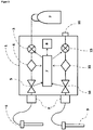
- FIG. 1 shows an embodiment of an insufflator according to the invention.
- the insufflator (1) is connected to a gas source (2), for example in the form of a CO 2 gas bottle.
- the insufflation trocar (6) is fed via a proportional valve (3), a pressure sensor (4), a volume flow sensor (5) and a filter (F).
- the separate desufflation trocar (9) is connected to the insufflator via a hose, the gas flow initially again leading via a filter (F) a volume flow sensor (10) a pressure sensor (11) to a suction pump (12).
- the outlet of the suction pump leads to a device outlet (13).
- the device outlet (13) can of course be equipped with an additional filter.
- the measurement data of the pressure sensors (4, 11) and the volume flow sensors (5, 10) are transmitted to the computing unit (7) with the connected memory (8).
- the processing unit (7) controls the proportional valve (3) and the suction pump (12).
- the positions of the pressure sensors and the volume flow sensors can also be localized differently: It is of course possible for the insufflation flow to first pass through the volume flow sensor (5) and then through the pressure sensor (4). Similarly, it is possible for the volume flow sensor (10) of the desufflation line to be located after the suction pump (12) in the direction of flow.
- FIG 2 shows a device according to the invention in which the suction pump (12) runs continuously and the suction power is controlled by a by-pass valve (14).
- the by-pass valve (14) is also controlled via the computing unit (7) (in the Figure 2 not shown).
- FIG. 3 shows a further variant of the device according to the invention.
- a connection (16) for an external pump is provided instead of an internal suction pump.
- Many hospitals are equipped with appropriate pumps that can be used for the intended use of an insufflator according to the invention.
- only a control valve (15) is required to regulate the suction rate of the external pump (not shown).
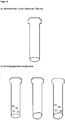
- Figure 4 shows embodiments of suction trocars.
- Figure 4a shows a conventional (cylindrical) trocar with corresponding connections.
- Figure 4b shows various suction trocars according to the invention that either have openings in the cylinder wall (left) or are irregularly designed in the area of the cylinder end (center) or have both openings in the cylinder wall and an irregularly shaped end piece (right).
- the decisive factor here is that the end of the cylinder does not sit on tissue and suck on it. The openings provided effectively prevent such seizing.
- the individual components of the device according to the invention are for the most part already known from earlier publications such as, for example US 6299592 , US5411474 , WO1996001132A1 , WO 2011041387A1 , US 5800381 , DE 4219859B4 , DE 102015000845A1 but not in connection with a device according to the invention as defined by the claims.
- a suitably programmed microcomputer with associated memory and input and output devices serves as the control unit.
- Volume flow sensors are already known from other medical devices (for example in the context of ventilation devices), so that they do not need to be discussed further at this point.
Landscapes
- Health & Medical Sciences (AREA)
- Life Sciences & Earth Sciences (AREA)
- General Health & Medical Sciences (AREA)
- Heart & Thoracic Surgery (AREA)
- Animal Behavior & Ethology (AREA)
- Engineering & Computer Science (AREA)
- Public Health (AREA)
- Veterinary Medicine (AREA)
- Biomedical Technology (AREA)
- Hematology (AREA)
- Anesthesiology (AREA)
- Surgical Instruments (AREA)
- Endoscopes (AREA)
- Surgery (AREA)
- Pathology (AREA)
- Molecular Biology (AREA)
- Medical Informatics (AREA)
- Nuclear Medicine, Radiotherapy & Molecular Imaging (AREA)
- Infusion, Injection, And Reservoir Apparatuses (AREA)
Description
- Die vorliegende Erfindung betrifft einen Insufflator für die Laparoskopie, enthaltend eine Saugpumpe, wobei die Saugpumpe mittels eines separaten Schlauches mit dem Patienten verbunden ist und eine kontrollierte Entlüftung ermöglicht.
- Die Laparoskopie ist ein medizinischer Eingriff, bei dem die Bauchhöhle und die darin liegenden Organe visuell überprüft werden können. Hierzu werden üblicherweise kleine Hautschnitte (0,3 bis 2 Zentimeter) in die Bauchdecke gemacht und durch diese ein Trokar eingebracht, welcher wiederum eine optische Vorrichtung aufnehmen kann. Mithilfe eines speziellen Endoskops (Laparoskop) kann der Bauchraum eingesehen werden. Bei der diagnostischen Laparoskopie wird der Bauchraum lediglich visuell inspiziert, im Rahmen einer therapeutischen Laparoskopie können auch operative Eingriffe vorgenommen werden.
- Üblicherweise wird zu Beginn der Laparoskopie zunächst der Bauchraum mit Gas befüllt, um ein Pneumoperitoneum zu schaffen. Hierzu sind bereits verschiedene Gase verwendet worden, wie z. B. Luft, Stickstoff oder Kohlendioxid (CO2). Die Verwendung von Kohlendioxidgas hat sich besonders gut bewährt.
- Nach dem Ende der Operation muss das eingeführte Gas wieder entfernt werden (Entlüftung oder Desufflation). Dies wird heutzutage unkontrolliert durch Öffnen eines Trokaranschlusses durchgeführt. Dabei ergeben sich insbesondere folgende Probleme:
- 1) Das im Patienten vorhandene Gas wird ungefiltert in den Operationsraum abgelassen. Damit ist das OP-Personal direkt den giftigen Rauchgasen ausgesetzt
- 2) Durch die unkontrollierte Entlüftung besteht ein höheres Risiko des Verbleibs von CO2 im Patienten. Durch die dadurch notwendige Absorption des CO2 durch den Körper entsteht oftmals ein postoperativer Schmerz ("shoulderpain").
- 3) Durch die unkontrollierte Entlüftung fällt der Bauchraum unverhältnismäßig schnell zusammen.
- Die im Stand der Technik beschriebenen Insufflationseinrichtungen, die Saugvorrichtungen aufweisen (z.B.
DE4219859 A1 ,WO 2004/ 009167 A1 oderWO 2011/041387 A1 ) sind aus Sicherheitsgründen nicht zur Entlüftung geeignet. - Die Aufgabe der vorliegenden Erfindung ist es, eine kontrollierte und sichere Desufflation des Patienten zu ermöglichen und die benannten Nachteile zu vermeiden.
- Die Lösung dieser Aufgabe erfolgt durch den Gegenstand der Patentansprüche, d. h. eine Insufflationseinrichtung mit Saugpumpe sowie einer Insufflations- und einer separaten Desufflationsleitung wobei sowohl in der Insufflations-, als auch in der Desufflationsleitung ein Drucksensor und ein Volumenstromsensor vorhanden ist, so dass der Druck in beiden Leitungen zeitgleich gemessen werden kann.
- Die Lösung der Aufgabe erfolgt insbesondere durch einen
Insufflationseinrichtung zur Verwendung in der Medizintechnik enthaltend
einen Insufflator zur Gasversorgung mit einer Gasquelle,
eine Regelungseinheit,
eine Insufflationsleitung und eine separate Desufflationsleitung,
wobei die Desufflationsleitung mit einer Saugpumpe verbunden ist,
wobei die Insufflationsleitung und die Desufflationsleitung je einen Drucksensor und je einen Volumenstromsensor aufweisen,
wobei der Insufflator eine Vorrichtung zur kontrollierten Absaugung des im Patienten befindlichen Gases aufweist
wobei die Regelungseinheit die Leistung der Saugpumpe in Abhängigkeit von der Druckmessung des Drucksensoren steuert,
wobei die Regelungseinheit eine Aktivierungssperre enthält, die eine Aktivierung der Saugpumpe verhindert, wenn der mittels des Drucksensors in der Insufflationsleitung gemessene Druck kleiner als ein eingestellter Schwellwert ist,
wobei die Aktivierungssperre ferner eine Aktivierung der Saugpumpe verhindert, wenn der mittels des Drucksensors in der Insufflationsleitung gemessene Druck und der mittels des Drucksensors in der Absaugleitung gemessene Drucks nicht identisch sind - Um eine Desufflation zu ermöglichen, wird der Insufflator unter Zuhilfenahme zweier Schläuche mit dem Patienten verbunden. Der erste Schlauch wird zur Insufflation verwendet. Gas wird im Rahmen der Operation dem Patienten zugeführt, um den Druck im Abdomen aufbauen zu können. Weiterhin wird die abdominale Druckmessung über diese Leitung durchgeführt. Der zweite Schlauch kann bereits während der Durchführung der Operation mit dem Patienten verbunden werden, um beispielsweise eine Rauchgasabsaugung zu realisieren (
Figur 1 ). - Als Absaugpumpen kommen elektronisch geregelte Pumpen in Frage, wie sie beispielsweise in der Vorrichtung gemäß
DE 102013016063 oder ähnlichen Druckschriften beschrieben sind.
Alternativ kann beispielsweise die Saugpumpe über ein ByPass-Ventil gesteuert werden (Figur 2 ). Hierzu kann beispielsweise die Pumpe auf eine bestimmte Leistung eingestellt werden, welche weitestgehend konstant ist, und die Regelung der Leistung erfolgt dann über das ByPass-Ventil.
Weiterhin alternativ kann auch ein Steuerungsventil direkt in die Absaugleitung positioniert werden (Figur 3 ). Auf diese Weise könnten sogar externe Pumpen verwendet werden, beispielsweise die im OP vorhandene Wandabsaugung. Die Regelungseinheit des Insufflators regelt dann die Absaugleistung über das dargestellte Steuerungsventil. - Nach dem Stopp der Insufflation wird durch den Insufflator dem Benutzer die Möglichkeit gegeben, die Desufflation zu starten. Beim Start des Desufflationsvorgangs prüft der Insufflator zunächst den gemessenen Abdominaldruck über die Insufflationsleitung. Ist dieser geringer als ein einstellbarer Schwellwert (<5 mmHg, bevorzugt < 3 mmHg), bewirkt eine Aktivierungssperre, dass die Desufflation nicht gestartet wird. Der genannte Schwellwert kann geräteseitig voreingestellt sein. In besonderen Ausführungsformen der Erfindung kann ein Wählschalter oder eine andere Wähleinrichtung vorhanden sein, mit der der Schwellwert präoperativ vom Bedienpersonal eingestellt werden kann. Liegt der gemessene Abdominaldruck über dem eingestellten Schwellwert, dann wird der über die Insufflationsleitung gemessene Abdominaldruck mit dem gemessenen Druck auf der Absaugleitung verglichen. Ist dieser identisch kann davon ausgegangen werden, dass beide Schläuche mit dem Patienten verbunden sind. Die beiden gemessenen Druckwerte werden als identisch angesehen, wenn ihre Differenz kleiner ist als 2 mmHg.
- Sind diese Voraussetzungen erfüllt, kann die Saugpumpe aktiviert werden.Die Absaugrate darf aus Sicherheitsgründen nicht zu hoch sein, sie sollte aber auch nicht zu gering sein, um die Behandlung nicht unnötig in die Länge zu ziehen. Als sinnvoll hat sich eine Absaugrate von 1-5 I/ min. bevorzugt ca. 3 I/min. erwiesen.
- Der abdominale Druck wird weiterhin über die Insufflationsleitung überwacht. Sobald der abdominale Druck unterhalb einer bestimmten Grenze liegt (z.B. 5, 4 oder 3 mmHg) wird die Desufflation gestoppt. Die Druckgrenze (von z.B. 5, 4 oder 3 mmHg) kann geräteseitig voreingestellt sein. Üblicherweise ist ein Wählschalter oder eine andere Wähleinrichtung vorhanden, mit der die Druckgrenze vor der Operation vom Bedienpersonal eingestellt werden kann.
- Wenn während der Desufflation die Insufflationsleitung durch einen Verschluss (z.B. durch Schließen des Stopcocks am Trokar) oder durch fehlende Verbindung (z. B. frühes Entfernen des Trokars) den abdominalen Druck nicht mehr korrekt messen kann, besteht die Gefahr einer zu späten Abschaltung der Desufflation und damit eines negativen Druckes im Patienten.
- Im Patent Northgate
US Pat 6,299,592 wird ein Verfahren beschrieben, wie ein Verschluss in der Insufflationsleitung erkannt werden kann. Bei diesem erfolgt jedoch eine ständige Insufflation in der Insufflationsleitung. Da ein zusätzliches Zuführen von Gas während des Absaugens kontraproduktiv ist, wird im Folgenden ein anderes Verfahren dargestellt um die Sicherheit zu gewährleisten. - Im Rahmen der erfindungsgemäßen Vorrichtung wird die Desufflation intervallartig unterbrochen. Nach dem Abschalten der Saugpumpe wird jeweils eine gewisse Zeit gewartet, bis der Druckausgleich stattgefunden hat. Dieser ist u.a. abhängig vom Strömungswiderstand und je nach Anwendungsfall variabel. Um zum Einen zügig den abdominalen Druck zu reduzieren und zum Anderen die Wartezeit zum Druckausgleich zu gewährleisten, sollte bevorzugt dynamisch gewartet werden. Das Ende der Wartezeit ist erreicht, wenn ein stabiler Druck auf der Saugseite vorliegt. Es wird anschließend geprüft, ob der gemessene Abdominaldruck auf der Insufflationsleitung dem gemessenen Druck in der Desufflationleitung entspricht. Ist dies nicht der Fall, wird die Desufflation gestoppt. Andernfalls wird die Desufflation fortgesetzt.
- Zu Beginn der Desufflation beträgt das Zeitintervall, in welchem gesaugt wird beispielsweise zwischen 10 und 1 Sekunden, besonders bevorzugt 5-3 Sekunden. Das Messintervall beträgt typischerweise zwischen 5 und 0,5 Sekunden.
- Sollte eine größere Leckage im Bereich des Abdomens (z.B. durch einen weiteren Trokar) oder ein kleines Volumen im Abdomen vorhanden sein, besteht jedoch weiterhin die Gefahr, einen Unterdruck im Patienten zu erzeugen.Der oben beschriebene Algorithmus erkennt nur in festen Intervallen (z.B. alle 3 Sekunden) den Gleichlauf der beiden Drucksensoren. Dieses Intervall ist für diese Fälle zu lang, um sicher einen Unterdruck zu erkennen. Eine Verkürzung der Intervalle führt zu einer unzureichenden Absaugrate.
- Aus diesem Grund muss während der aktiven Absaugung ein Plausibilitätstest durchgeführt werden. Sinkt der Abdominaldruck im Verhältnis zum abgesaugten Volumen während des Absaugvorgangs zu langsam (z.B. größer 0,3 Liter/mmHg als Erwartungswert für einen durchschnittlichen Patienten) wird die Desufflation unterbrochen. Dieses Volumen wird mit dem vorhandenen Sensor zur Volumenstrommessung bestimmt.
- In einer bevorzugten Ausführungsform der Erfindung wird während der Insufflation des Patienten der abdominale Druckanstieg ermittelt, in ein Verhältnis zum insufflierten Volumen gesetzt und gespeichert. Auf diese Weise kann beispielsweise ermittelt werden, dass für einen Druckanstieg von 1 mmHg ein Gasfluss von 0,35 Liter erforderlich ist. Dieser Wert wird in der Regelungseinheit gespeichert. Für die Desufflation desselben Patienten ist zu erwarten, dass pro 0,35 Liter abgepumpten Gases ein Druckabfall von 1 mmHg eintritt (Erwartungswert: 0,35l/mmHg). Während der Desufflation wird der Druckabfall pro Gasvolumen überwacht. Sollte der Erwartungswert signifikant über- oder unterschritten werden (z.B. um mehr als 20%) wird die Desufflation automatisch gestoppt.
- Alternativ kann eine kontinuierliche Überprüfung des abdominalen Drucks mit Hilfe des Drucksensors auf der Saugseite erfolgen. Diese Überprüfung basiert auf einem mathematischen Beobachtermodell (z.B. Luenberger-Beobachter), der auf Basis des Modells der Regelstrecke entworfen wurde. Derartige Modelle sind im Stand der Technik beschrieben (
WO 2016/119773 A1 ) und benötigen daher keine weiteren Erläuterungen an dieser Stelle. Auf diese Weise kann während der Absaugung bereits ein Gleichlauf der beiden Drucksensoren überwacht und bei Abweichung die Desufflation unterbrochen werden. - Neben einem Verschluss in der Insufflationsleitung muss auch ein Verschluss in der Saugleitung erkannt werden, um keine Gewebeschäden zu verursachen (z. B. Ansaugen von Organen). Auf der Saugseite wird bei der Reduzierung des abgesaugten Volumenstroms oder bei zu hohem Unterdruck ein Verschluss auf Saugseite erkannt und die Desufflation ebenfalls unterbrochen. Es wird in diesen Fällen anschließend geprüft, obder gemessene Abdominaldruck auf der Insufflationsleitung dem gemessenen Druck in der Desufflationleitung entspricht. Ist dies nicht der Fall, wird die Desufflation gestoppt. Andernfalls wird die Desufflation fortgesetzt.
- Ergänzend kann die Absaugung mittels spezieller Saugtrokare erfolgen. Klassische Trokare sind im Wesentlichen stiftförmige (zylinderförmige) Rohre mit einer kreisrunden Öffnung, die im Anwendungsfall im Bauchraum des Patienten positioniert ist, und diversen Anschlussmöglichkeiten außerhalb des Patienten. Bei der Absaugung von Gas im Rahmen der Desufflation besteht die Gefahr, dass sich die Ansaugöffnung an empfindlichen Gewebeteilen festsaugt. Diese Gefahr wird verringert wenn die Trokare so ausgestaltet sind, dass die Zylinderwand im Endteil Öffnungen aufweisen. In einer bevorzugten Ausführungsform enthält der Trokar im Bereich der Öffnung Belüftungsausnehmungen (
Figur 4 ). -
Figur 1 zeigt eine Ausführungsform eines erfindungsgemäßen Insufflators. Der Insufflator (1) ist an eine Gasquelle (2), z.B. in Form einer CO2-Gasflasche angeschlossen. Über ein Proportionalventil (3), einen Drucksensor (4), einen Volumenstromsensor (5) und einen Filter (F) dem Insufflationstrokar (6) zugeführt. Der separate Desufflationstrokar (9) ist über einen Schlauch mit dem Insufflator verbunden, wobei der Gasflusszunächst wieder über einen Filter (F) einen Volumenstromsensor (10) einem Drucksensor (11) zu einer Saugpumpe (12) führt. Der Ausgang der Saugpumpe führt zu einem Geräteauslass (13). Der Geräteauslass (13) kann selbstverständlich mit einem zusätzlichen Filter ausgestattet sein. Die Messdaten der Drucksensoren (4, 11) sowie der Volumenstromsensoren (5,10) werden an die Recheneinheit (7) mit angeschlossenem Speicher (8) übermitteilt. Die Recheneinheit (7) steuert das Proportionalventil (3) sowie die Saugpumpe (12). Wie der Fachmann erkennen wird, können die Positionen der Drucksensoren und der Volumenstromsensoren auch anders lokalisiert sein: So ist es selbstverständlich möglich, dass der Insufflationsstrom zunächst durch den Volumenstromsensor (5) und dann durch den Drucksensor (4) geführt wird. Ähnlich ist es möglich, dass der Volumenstromsensor (10) der Desufflationsleitung in Strömungsrichtung erst nach der Saugpumpe (12) liegt. -
Figur 2 zeigt eine erfindungsgemäße Vorrichtung, bei der die Saugpumpe (12) kontinuierlich läuft und die Absaugleistung durch ein By-Pass-Ventil (14) gesteuert wird. Das By-Pass-Ventil (14) wird ebenfalls über die Recheneinheit (7) gesteuert (in derFigur 2 nicht dargestellt). -
Figur 3 zeigt eine weitere Variante der erfindungsgemäßen Vorrichtung. Hierbei wird statt einer geräteinternen Saugpumpe ein Anschluss (16) für eine externe Pumpe vorgesehen. Viele Krankenhäuser sind mit entsprechenden Pumpen ausgestattet, die für den vorgesehenen Einsatz eines erfindungsgemäßen Insufflators verwendet werden können. In diesem Fall wird lediglich ein Steuerungsventil (15) benötigt, um die Saugrate der externen Pumpe (nicht dargestellt) zu regulieren. -
Figur 4 zeigt Ausführungsformen von Saugtrokaren.Figur 4a zeigt einen herkömmlichen (zylinderförmigen) Trokar mit entsprechenden Anschlüssen.Figur 4b zeigt verschiedene erfindungsgemäße Saugtrokare, die entweder Öffnungen in der Zylinderwand aufweisen (links) oder im Bereich des Zylinderendes unregelmäßig ausgestaltet sind (Mitte) oder sowohl Öffnungen in der Zylinderwand, wie auch eine unregelmäßig geformtes Endstück aufweisen (rechts). Entscheidend hierbei ist, dass das Ende des Zylinders nicht auf Gewebe aufsitzen und sich daran festsaugen kann. Durch die vorgesehenen Öffnungen wird ein derartiges Festsaugen wirkungsvoll verhindert. - Die Einzelkomponenten der erfindungsgemäßen Vorrichtung sind größtenteils bereits aus früheren Druckschriften bekannt wie z.B.
US 6299592 ,US5411474 ,WO1996001132A1 ,WO 2011041387A1 ,US 5800381 ,DE 4219859B4 ,DE 102015000845A1 , jedoch nicht im Zusammenhang mit einer erfindungsgemäßen Vorrichtung, wie sie durch die Ansprüche definiert sind. Als Regelungseinheit dient ein entsprechend programmierter Microcomputer mit dazugehörigen Speicher sowie Eingabe-und Ausgabevorrichtungen. Volumenstromsensoren sind bereits aus anderen medizintechnischen Vorrichtungen bekannt (z.B. im Rahmen von Beatmungsvorrichtungen), so dass sie an dieser Stelle nicht weiter erörtert werden müssen. - Der Fachmann auf dem Gebiet kann alternative und/oder ergänzende Ausführungsformen der Erfindung realisieren, ohne erfinderisch tätig werden zu müssen.
Claims (9)
- Insufflationseinrichtung zur Verwendung in der Medizintechnik enthaltend
einen Insufflator (1) zur Gasversorgung mit einer Gasquelle (2),
eine Regelungseinheit (7),
eine Insufflationsleitung mit einem Trokar (6) und eine separate Desufflationsleitung mit einem Trokar (9),
wobei die Desufflationsleitung mit einer Saugpumpe (12) verbunden ist,
wobei die Insufflationsleitung und die Desufflationsleitung je einen Drucksensor (4, 11) und je einen Volumenstromsensor (5, 10) aufweisen,
wobei der Insufflator eine Vorrichtung zur kontrollierten Absaugung des im Patienten befindlichen Gases aufweist
wobei die Regelungseinheit (7) die Leistung der Saugpumpe (12) in Abhängigkeit von der Druckmessung des Drucksensoren (4, 11) steuert,
dadurch gekennzeichnet, dass die Regelungseinheit (7) eine Aktivierungssperre enthält, die eine Aktivierung der Saugpumpe (12) verhindert, wenn der mittels des Drucksensors (4) in der Insufflationsleitung gemessene Druck kleiner als ein eingestellter Schwellwert ist,
wobei die Aktivierungssperre ferner eine Aktivierung der Saugpumpe (12) verhindert, wenn der mittels des Drucksensors (4) in der Insufflationsleitung gemessene Druck und der mittels des Drucksensors (11) in der Absaugleitung gemessene Drucks nicht identisch sind. - Insufflationseinrichtung zur Verwendung in der Medizintechnik gemäß Anspruch 1, wobei der Schwellwert kleiner als 5 mmHg ist.
- Insufflationseinrichtung zur Verwendung in der Medizintechnik gemäß Anspruch 1, wobei der Schwellwert kleiner als 3 mmHg ist.
- Insufflationseinrichtung zur Verwendung in der Medizintechnik gemäß mindestens einem der Ansprüche 1 bis 3, wobei die Regelungseinheit (7) die Saugpumpe (12) zyklisch deaktiviert, und während der Saugpausen, die Druckwerte der beiden Drucksensoren (4,11) vergleicht, wobei nur bei identischen Werten die Saugpumpe wieder aktiviert wird.
- Insufflationseinrichtung zur Verwendung in der Medizintechnik gemäß mindestens einem der Ansprüche 1 bis 4, wobei die Regelungseinheit (7) das abgesaugte Volumen ins Verhältnis zum sinkenden abdominalen Druck setzt und wobei die Regelungseinheit (7) die Saugpumpe (12) deaktiviert, wenn dieses Verhältnis nicht einem Erwartungswert entspricht.
- Insufflationseinrichtung zur Verwendung in der Medizintechnik gemäß Anspruch 5, wobei die Regelungseinheit (7) den Erwartungswert des Verhältnisses von abgesaugtem Volumen zu sinkenden abdominalen Druck während der Insufflationsphase durch Messung des abdominalen Druckanstiegs zum Verhältnis des insufflierten Volumens während der Insufflationsphase ermittelt und speichert.
- Insufflationseinrichtung zur Verwendung in der Medizintechnik gemäß mindestens einem der Ansprüche 1 bis 5, wobei die Regelungseinheit die Saugpumpe kontinuierlich aktiviert, und den Druck des Bauchraumes über den Drucksensor (11) der Desufflationsleitung mittels eines mathematischen Beobachtermodell schätzt und mit dem Druck des Drucksensors in der Insufflationsleitung (4) vergleicht, wobei nur bei identischen Werten die Saugpumpe (12) aktiviert bleibt.
- Insufflationseinrichtung zur Verwendung in der Medizintechnik gemäß Anspruch 7, wobei das mathematische Beobachtermodell nach Art eines Luenberger-Beobachters ausgestaltet ist.
- Insufflationseinrichtung zur Verwendung in der Medizintechnik gemäß mindestens einem der Ansprüche 1 bis 4, wobei die Desufflationsleitung mit einem zylinderförmigen Trokar (9) verbunden, wobei der zylinderförmige Trokar so ausgestaltet ist, dass er Ausnehmungen in der Zylinderwand aufweist.
Applications Claiming Priority (2)
| Application Number | Priority Date | Filing Date | Title |
|---|---|---|---|
| DE102016014980.9A DE102016014980A1 (de) | 2016-12-16 | 2016-12-16 | Medizintechnische Pumpe mit verbesserter Entlüftung |
| PCT/DE2017/000428 WO2018108200A1 (de) | 2016-12-16 | 2017-12-18 | Medizintechnische pumpe mit verbesserter desufflation |
Publications (2)
| Publication Number | Publication Date |
|---|---|
| EP3554598A1 EP3554598A1 (de) | 2019-10-23 |
| EP3554598B1 true EP3554598B1 (de) | 2020-08-19 |
Family
ID=61131868
Family Applications (1)
| Application Number | Title | Priority Date | Filing Date |
|---|---|---|---|
| EP17837849.3A Active EP3554598B1 (de) | 2016-12-16 | 2017-12-18 | Medizintechnische pumpe mit verbesserter desufflation |
Country Status (7)
| Country | Link |
|---|---|
| US (2) | US20190307972A1 (de) |
| EP (1) | EP3554598B1 (de) |
| JP (1) | JP7080233B2 (de) |
| CN (1) | CN110049798B (de) |
| DE (1) | DE102016014980A1 (de) |
| ES (1) | ES2831858T3 (de) |
| WO (1) | WO2018108200A1 (de) |
Families Citing this family (9)
| Publication number | Priority date | Publication date | Assignee | Title |
|---|---|---|---|---|
| DE102016014980A1 (de) | 2016-12-16 | 2018-06-21 | W.O.M. World Of Medicine Gmbh | Medizintechnische Pumpe mit verbesserter Entlüftung |
| DE102018004211A1 (de) * | 2018-05-25 | 2019-11-28 | W.O.M. World Of Medicine Gmbh | Insufflationsvorrichtung und damit durchführbare Betriebsverfahren |
| DE102018005314A1 (de) * | 2018-07-05 | 2020-01-09 | W.O.M. World Of Medicine Gmbh | lnsufflationsvorrichtung mit intelligenter Steuerung der Rauchgasabsaugung |
| CA3150371A1 (en) * | 2019-09-12 | 2021-03-18 | Oscar Diaz Cambronero | A modular system for monitoring and controlling the homeostasis in cavities, and a method for generating a volume of fluid in a cavity |
| EP4076604B1 (de) * | 2019-12-18 | 2024-05-08 | W.O.M. World of Medicine GmbH | Gehäuseanordnung eines rauchgasfiltrationssystems mit einer integrierten möglichkeit zur flüssigkeitsabscheidung |
| CN111685831B (zh) * | 2020-06-15 | 2024-09-13 | 南京图格医疗科技有限公司 | 一种恒压变流式气腹机 |
| CN112057122A (zh) * | 2020-09-18 | 2020-12-11 | 西安交通大学医学院第一附属医院 | 内科胸腔镜自动充气装置 |
| DE102021002547A1 (de) * | 2021-05-17 | 2022-11-17 | W.O.M. World Of Medicine Gmbh | Medizintechnische Pumpe für die Endoskopie |
| DE102022001357A1 (de) * | 2022-04-20 | 2023-10-26 | W.O.M. World Of Medicine Gmbh | Ilnsufflator mit Vorrichtung zur Erfassung der Filterbelegung |
Family Cites Families (70)
| Publication number | Priority date | Publication date | Assignee | Title |
|---|---|---|---|---|
| US3954920A (en) | 1973-09-04 | 1976-05-04 | Parkland International Inc. | Gas humidification system |
| US5476447A (en) * | 1983-06-28 | 1995-12-19 | Olympus Optical Co., Ltd. | Intraperitoneal therapy apparatus |
| JP2544880B2 (ja) * | 1992-10-16 | 1996-10-16 | オリンパス光学工業株式会社 | 気腹装置の煙除去システム |
| NL8702698A (nl) * | 1987-11-11 | 1989-06-01 | Leuven Res & Dev Vzw | Gas-insufflatiesysteem bij endoscopie en een chirurgische endoscoop daarvoor. |
| AU660718B2 (en) | 1991-10-04 | 1995-07-06 | Fisher & Paykel Healthcare Limited | Improvements in or relating to humidifiers |
| DE4219859B4 (de) | 1992-06-17 | 2005-12-29 | Erbe Elektromedizin Gmbh | Insufflator |
| US5246419A (en) | 1992-09-04 | 1993-09-21 | Omnivision, Inc. | Intra-abdominal insufflation apparatus |
| JP3197380B2 (ja) * | 1993-01-13 | 2001-08-13 | オリンパス光学工業株式会社 | 気腹装置 |
| US5411474A (en) | 1993-07-14 | 1995-05-02 | Douglas E. Ott | Method and apparatus for conditioning insufflation gas for laparoscopic surgery |
| DE4339876A1 (de) * | 1993-11-23 | 1995-05-24 | Walz Elektronik Gmbh | Vorrichtung zum Insufflieren |
| US5800381A (en) | 1994-02-25 | 1998-09-01 | Ognier; Jean-François | Medical gas insufflator with automatic gas flow control |
| WO1996001132A1 (en) | 1994-07-01 | 1996-01-18 | Northgate Technologies Incorporated | High flow insufflation instrument for laparoscopic surgery |
| DE19534001B4 (de) | 1994-09-20 | 2006-05-18 | Fisher & Paykel, East Tamaki | Befeuchterkammer |
| AUPO425496A0 (en) | 1996-12-18 | 1997-01-16 | William A Cook Australia Pty Ltd | Medical humidifier |
| CA2617287C (en) | 1997-06-17 | 2011-11-15 | Fisher & Paykel Healthcare Limited | Respiratory humidification system |
| US6299592B1 (en) | 1998-03-31 | 2001-10-09 | Northgate Technologies Inc. | Laparoscopic insufflator |
| US9028437B2 (en) | 1998-05-19 | 2015-05-12 | Lexion Medical, Llc | Method for delivering an agent to the abdomen |
| US7918816B2 (en) | 1998-05-19 | 2011-04-05 | Lexion Medical, Llc | Method and apparatus for delivering an agent to the abdomen |
| US7731704B2 (en) | 1998-05-19 | 2010-06-08 | Lexion Medical, Llc | Method and apparatus for delivering an agent to the abdomen |
| US20050107767A1 (en) | 1998-05-19 | 2005-05-19 | Ott Douglas E. | Method and apparatus for delivering an agent to the abdomen |
| US6068609A (en) | 1998-05-19 | 2000-05-30 | Douglas E. Ott | Method and apparatus for conditioning gas for medical procedures having humidity monitoring and recharge alert |
| US7744557B2 (en) | 1998-05-19 | 2010-06-29 | Lexion Medical, Llc | Method and apparatus for delivering an agent to the abdomen |
| US7250035B1 (en) | 1998-05-19 | 2007-07-31 | Lexion Medical, Llc | Method and apparatus for treating gas for delivery to an animal |
| AT3403U1 (de) | 1998-09-25 | 2000-02-25 | E & E Elektronik Gmbh | Vorrichtung zur erzeugung einer definierten relativen luftfeuchte |
| AU756477C (en) | 1998-12-23 | 2003-09-11 | Fisher & Paykel Healthcare Limited | Fault protection system for a respiratory conduit heater element |
| SE522908C2 (sv) | 1999-05-10 | 2004-03-16 | Aneo Ab | Arrangemang för att kunna tilldela en levande varelse ett anestesialt tillstånd |
| IT1318430B1 (it) | 2000-03-29 | 2003-08-25 | Mallinckrodt Holdings B V | Dispositivo per l'umidificazione passiva di pazienti tracheostomizzati o intubati. |
| US6976489B2 (en) | 2000-06-30 | 2005-12-20 | Northgate Technologies, Inc. | Method and apparatus for humidification and warming of air |
| US6827340B2 (en) | 2000-08-14 | 2004-12-07 | Taga Medical Technologies, Inc. | CPAP humidifier |
| CA2424647C (en) | 2000-10-16 | 2009-09-08 | Fisher & Paykel Healthcare Limited | Improvements to apparatus used for the humidification of gases in medical procedures |
| US6689117B2 (en) | 2000-12-18 | 2004-02-10 | Cardiac Pacemakers, Inc. | Drug delivery system for implantable medical device |
| DE10139881B4 (de) | 2001-08-20 | 2017-06-08 | Resmed R&D Germany Gmbh | Vorrichtung zur Zufuhr eines Atemgases und Verfahren zur Steuerung derselben |
| US20030181857A1 (en) | 2002-03-22 | 2003-09-25 | James Blake | Insufflation device with integral heater control |
| US6592543B1 (en) | 2002-04-03 | 2003-07-15 | Surgin Inc. | Fluid flow regulator for a smoke evacuation system and method of using same |
| EP1507567B1 (de) | 2002-05-29 | 2006-11-29 | BVBA Medisize Belgie | Vorrichtung zum Anwärmen und Befeuchten von Atemgasen |
| US6842314B2 (en) | 2002-05-29 | 2005-01-11 | Headway Technologies, Incorporated | Magnetoresistive device and method of manufacturing same, and thin-film magnetic head and method of manufacturing same |
| US8118769B2 (en) | 2002-07-19 | 2012-02-21 | Storz Endoskop Produktions Gmbh | Apparatus for conditioning an insufflation gas |
| DE10233861A1 (de) * | 2002-07-19 | 2004-02-12 | Storz Endoskop Produktions Gmbh | Vorrichtung, Insufflationsvorrichtung, Messvorrichtung und Verfahren zur Insufflation einer Körperhöhle mit einem Insufflationsgas |
| US7204248B2 (en) | 2002-09-27 | 2007-04-17 | Cook Critical Care Incorporated | Fiberoptic nebulizer |
| DE10251134A1 (de) | 2002-10-31 | 2004-05-19 | GRÜNDLER GmbH | Beatmungsvorrichtung und Verfahren |
| US7476212B2 (en) | 2003-06-12 | 2009-01-13 | Michael Spearman | Medical gas humidification system |
| US7811253B2 (en) | 2004-12-09 | 2010-10-12 | Applied Medical Resources Corporation | Insufflation gas warmer and humidifier |
| US20070249990A1 (en) * | 2006-04-20 | 2007-10-25 | Ioan Cosmescu | Automatic smoke evacuator and insufflation system for surgical procedures |
| US8211052B1 (en) | 2006-07-13 | 2012-07-03 | Lexion Medical Llc | Charged hydrator |
| GB0615872D0 (en) | 2006-08-10 | 2006-09-27 | Intersurgical Ag | Improvements relating to humidification chambers |
| US8414550B2 (en) | 2006-09-29 | 2013-04-09 | Lexion Medical, Llc | System and method to vent gas from a body cavity |
| FR2908048B1 (fr) * | 2006-11-08 | 2009-02-06 | Sopro Sa | Dispositif d'insufflation de gaz permettant une utilisation optimale et securitaire des recipients de gaz sous pression |
| US8333195B2 (en) | 2007-07-18 | 2012-12-18 | Vapotherm, Inc. | System and method for delivering a heated and humidified gas |
| US8269638B2 (en) | 2008-01-23 | 2012-09-18 | Lexion Medical Llc | Hydration alert |
| WO2009111430A1 (en) * | 2008-03-03 | 2009-09-11 | Applied Medical Resources Corporation | Balloon trocar advanced fixation |
| US8932248B2 (en) | 2009-03-18 | 2015-01-13 | Lexion Medical Llc | Gas conditioning trocars |
| US20110028795A1 (en) * | 2009-07-29 | 2011-02-03 | Tyco Healthcare Group Lp | Surgical portal device including textured surface |
| EP2482869B1 (de) | 2009-09-29 | 2019-09-25 | SurgiQuest, Incorporated | Multmodales chirurgisches gasverabreichungssystem für laparoskopische eingriffe |
| US8444591B2 (en) | 2009-10-09 | 2013-05-21 | John Temple | Insufflation gas heater system and tubing for use therewith |
| US20110230820A1 (en) | 2010-03-18 | 2011-09-22 | Aerosurgical Limited | Insufflation of body cavities |
| JP5566340B2 (ja) * | 2010-07-14 | 2014-08-06 | 富士フイルム株式会社 | 内視鏡の送気システム |
| US8608816B2 (en) | 2012-01-10 | 2013-12-17 | Buffalo Filter Llc | Fluid filtration device and system |
| WO2013120042A1 (en) | 2012-02-10 | 2013-08-15 | Intermountain Invention Management, Llc | Esophageal heat sensors |
| US20130255670A1 (en) | 2012-04-02 | 2013-10-03 | Lexion Medical, Llc | System and Method for Performing a Surgical Procedure |
| CN202802283U (zh) * | 2012-08-31 | 2013-03-20 | 淄博宏润工贸有限公司 | 一种医用真空负压抽吸系统 |
| ES2912252T3 (es) * | 2012-11-20 | 2022-05-25 | Surgiquest Inc | Sistemas para realizar la evacuación de humo durante procedimientos quirúrgicos laparoscópicos |
| US9962288B2 (en) * | 2013-03-07 | 2018-05-08 | Novartis Ag | Active acoustic streaming in hand piece for occlusion surge mitigation |
| CN105431093B (zh) * | 2013-08-06 | 2019-03-29 | 奥林巴斯株式会社 | 气腹装置 |
| DE102013016063A1 (de) | 2013-09-27 | 2015-04-02 | W. O. M. World of Medicine GmbH | Druckerhaltende Rauchgasabsaugung in einem Insufflator |
| WO2015098229A1 (ja) * | 2013-12-26 | 2015-07-02 | オリンパス株式会社 | 気腹装置 |
| JP6182100B2 (ja) * | 2014-04-09 | 2017-08-16 | 富士フイルム株式会社 | 送気システム及び送気装置 |
| US9581485B2 (en) | 2014-08-06 | 2017-02-28 | Magnetrol International, Incorporated | Removable magnetostrictive probe with automatic calibration |
| US9962520B2 (en) * | 2014-10-15 | 2018-05-08 | Surgiquest, Inc. | Branching multi-lumen tube set for laparoscopic surgical procedures involving smoke evacuation |
| DE102015000845A1 (de) | 2015-01-27 | 2016-07-28 | W.O.M. World Of Medicine Gmbh | Verfahren und Vorrichtung zur Regelung der Temperatur des Gasstroms bei medizintechnischen Vorrichtungen |
| DE102016014980A1 (de) | 2016-12-16 | 2018-06-21 | W.O.M. World Of Medicine Gmbh | Medizintechnische Pumpe mit verbesserter Entlüftung |
-
2016
- 2016-12-16 DE DE102016014980.9A patent/DE102016014980A1/de not_active Withdrawn
-
2017
- 2017-12-18 CN CN201780076152.1A patent/CN110049798B/zh active Active
- 2017-12-18 US US16/470,290 patent/US20190307972A1/en not_active Abandoned
- 2017-12-18 EP EP17837849.3A patent/EP3554598B1/de active Active
- 2017-12-18 JP JP2019527563A patent/JP7080233B2/ja active Active
- 2017-12-18 ES ES17837849T patent/ES2831858T3/es active Active
- 2017-12-18 WO PCT/DE2017/000428 patent/WO2018108200A1/de not_active Ceased
-
2021
- 2021-04-21 US US17/236,828 patent/US12214120B2/en active Active
Non-Patent Citations (1)
| Title |
|---|
| None * |
Also Published As
| Publication number | Publication date |
|---|---|
| JP7080233B2 (ja) | 2022-06-03 |
| US20210361886A1 (en) | 2021-11-25 |
| JP2020501643A (ja) | 2020-01-23 |
| WO2018108200A1 (de) | 2018-06-21 |
| DE102016014980A1 (de) | 2018-06-21 |
| US20190307972A1 (en) | 2019-10-10 |
| US12214120B2 (en) | 2025-02-04 |
| EP3554598A1 (de) | 2019-10-23 |
| CN110049798B (zh) | 2021-11-26 |
| CN110049798A (zh) | 2019-07-23 |
| ES2831858T3 (es) | 2021-06-09 |
Similar Documents
| Publication | Publication Date | Title |
|---|---|---|
| EP3554598B1 (de) | Medizintechnische pumpe mit verbesserter desufflation | |
| EP3049136B1 (de) | Druckerhaltende rauchgasabsaugung in einem insufflator | |
| EP3801710B1 (de) | Insufflationsvorrichtung | |
| DE69325037T2 (de) | Vorrichtung zur verbesserten insufflation | |
| DE69027430T2 (de) | Verfahren und vorrichtung zur okularen perfusion | |
| DE19510707A1 (de) | Verfahren und Vorrichtung zur Reinhaltung eines medizinischen Instruments | |
| DE19510712A1 (de) | Verfahren und Vorrichtung zur Einleitung eines Gases | |
| EP3295906B1 (de) | System zum durchführen einer phakoemulsifikation | |
| EP4340913B1 (de) | Medizintechnische pumpe für die endoskopie | |
| EP3006061A1 (de) | Verfahren zur Steuerung des Irrigationsdrucks | |
| DE2803646C3 (de) | Apparat zum Insufflieren von strömungsfähigen Medien | |
| EP4475921B1 (de) | Insufflationsvorrichtung mit neuartiger druckmessung | |
| WO2019020136A1 (de) | Vorrichtung und verfahren zur informationsverknüpfung und -auswertung von klinischen daten in einem medizinischen gerät | |
| EP4511092B1 (de) | Insufflationsvorrichtung mit schonmodus | |
| EP3817795B1 (de) | Insufflationsvorrichtung mit intelligenter steuerung der rauchgasabsaugung | |
| DE102018010318A1 (de) | Insufflationsvorrichtung und damit durchführbare Betriebsverfahren | |
| DE102019133075A1 (de) | Blutbehandlungsmaschine und Verfahren zur automatischen Füllstandsüberwachung und -Regelung eines Luftabscheiders mittels Frequenzanalyse | |
| DE202016003309U1 (de) | Gerät für positive Überdruckbeatmung |
Legal Events
| Date | Code | Title | Description |
|---|---|---|---|
| STAA | Information on the status of an ep patent application or granted ep patent |
Free format text: STATUS: UNKNOWN |
|
| STAA | Information on the status of an ep patent application or granted ep patent |
Free format text: STATUS: THE INTERNATIONAL PUBLICATION HAS BEEN MADE |
|
| PUAI | Public reference made under article 153(3) epc to a published international application that has entered the european phase |
Free format text: ORIGINAL CODE: 0009012 |
|
| STAA | Information on the status of an ep patent application or granted ep patent |
Free format text: STATUS: REQUEST FOR EXAMINATION WAS MADE |
|
| 17P | Request for examination filed |
Effective date: 20190620 |
|
| AK | Designated contracting states |
Kind code of ref document: A1 Designated state(s): AL AT BE BG CH CY CZ DE DK EE ES FI FR GB GR HR HU IE IS IT LI LT LU LV MC MK MT NL NO PL PT RO RS SE SI SK SM TR |
|
| AX | Request for extension of the european patent |
Extension state: BA ME |
|
| DAV | Request for validation of the european patent (deleted) | ||
| DAX | Request for extension of the european patent (deleted) | ||
| GRAP | Despatch of communication of intention to grant a patent |
Free format text: ORIGINAL CODE: EPIDOSNIGR1 |
|
| STAA | Information on the status of an ep patent application or granted ep patent |
Free format text: STATUS: GRANT OF PATENT IS INTENDED |
|
| INTG | Intention to grant announced |
Effective date: 20200525 |
|
| GRAS | Grant fee paid |
Free format text: ORIGINAL CODE: EPIDOSNIGR3 |
|
| GRAA | (expected) grant |
Free format text: ORIGINAL CODE: 0009210 |
|
| STAA | Information on the status of an ep patent application or granted ep patent |
Free format text: STATUS: THE PATENT HAS BEEN GRANTED |
|
| AK | Designated contracting states |
Kind code of ref document: B1 Designated state(s): AL AT BE BG CH CY CZ DE DK EE ES FI FR GB GR HR HU IE IS IT LI LT LU LV MC MK MT NL NO PL PT RO RS SE SI SK SM TR |
|
| REG | Reference to a national code |
Ref country code: CH Ref legal event code: EP |
|
| REG | Reference to a national code |
Ref country code: DE Ref legal event code: R096 Ref document number: 502017006875 Country of ref document: DE |
|
| REG | Reference to a national code |
Ref country code: AT Ref legal event code: REF Ref document number: 1303237 Country of ref document: AT Kind code of ref document: T Effective date: 20200915 |
|
| REG | Reference to a national code |
Ref country code: IE Ref legal event code: FG4D Free format text: LANGUAGE OF EP DOCUMENT: GERMAN |
|
| REG | Reference to a national code |
Ref country code: LT Ref legal event code: MG4D |
|
| REG | Reference to a national code |
Ref country code: NL Ref legal event code: MP Effective date: 20200819 |
|
| PG25 | Lapsed in a contracting state [announced via postgrant information from national office to epo] |
Ref country code: FI Free format text: LAPSE BECAUSE OF FAILURE TO SUBMIT A TRANSLATION OF THE DESCRIPTION OR TO PAY THE FEE WITHIN THE PRESCRIBED TIME-LIMIT Effective date: 20200819 Ref country code: NO Free format text: LAPSE BECAUSE OF FAILURE TO SUBMIT A TRANSLATION OF THE DESCRIPTION OR TO PAY THE FEE WITHIN THE PRESCRIBED TIME-LIMIT Effective date: 20201119 Ref country code: PT Free format text: LAPSE BECAUSE OF FAILURE TO SUBMIT A TRANSLATION OF THE DESCRIPTION OR TO PAY THE FEE WITHIN THE PRESCRIBED TIME-LIMIT Effective date: 20201221 Ref country code: HR Free format text: LAPSE BECAUSE OF FAILURE TO SUBMIT A TRANSLATION OF THE DESCRIPTION OR TO PAY THE FEE WITHIN THE PRESCRIBED TIME-LIMIT Effective date: 20200819 Ref country code: BG Free format text: LAPSE BECAUSE OF FAILURE TO SUBMIT A TRANSLATION OF THE DESCRIPTION OR TO PAY THE FEE WITHIN THE PRESCRIBED TIME-LIMIT Effective date: 20201119 Ref country code: SE Free format text: LAPSE BECAUSE OF FAILURE TO SUBMIT A TRANSLATION OF THE DESCRIPTION OR TO PAY THE FEE WITHIN THE PRESCRIBED TIME-LIMIT Effective date: 20200819 Ref country code: LT Free format text: LAPSE BECAUSE OF FAILURE TO SUBMIT A TRANSLATION OF THE DESCRIPTION OR TO PAY THE FEE WITHIN THE PRESCRIBED TIME-LIMIT Effective date: 20200819 Ref country code: GR Free format text: LAPSE BECAUSE OF FAILURE TO SUBMIT A TRANSLATION OF THE DESCRIPTION OR TO PAY THE FEE WITHIN THE PRESCRIBED TIME-LIMIT Effective date: 20201120 |
|
| PG25 | Lapsed in a contracting state [announced via postgrant information from national office to epo] |
Ref country code: IS Free format text: LAPSE BECAUSE OF FAILURE TO SUBMIT A TRANSLATION OF THE DESCRIPTION OR TO PAY THE FEE WITHIN THE PRESCRIBED TIME-LIMIT Effective date: 20201219 Ref country code: PL Free format text: LAPSE BECAUSE OF FAILURE TO SUBMIT A TRANSLATION OF THE DESCRIPTION OR TO PAY THE FEE WITHIN THE PRESCRIBED TIME-LIMIT Effective date: 20200819 Ref country code: NL Free format text: LAPSE BECAUSE OF FAILURE TO SUBMIT A TRANSLATION OF THE DESCRIPTION OR TO PAY THE FEE WITHIN THE PRESCRIBED TIME-LIMIT Effective date: 20200819 Ref country code: LV Free format text: LAPSE BECAUSE OF FAILURE TO SUBMIT A TRANSLATION OF THE DESCRIPTION OR TO PAY THE FEE WITHIN THE PRESCRIBED TIME-LIMIT Effective date: 20200819 Ref country code: RS Free format text: LAPSE BECAUSE OF FAILURE TO SUBMIT A TRANSLATION OF THE DESCRIPTION OR TO PAY THE FEE WITHIN THE PRESCRIBED TIME-LIMIT Effective date: 20200819 |
|
| PG25 | Lapsed in a contracting state [announced via postgrant information from national office to epo] |
Ref country code: EE Free format text: LAPSE BECAUSE OF FAILURE TO SUBMIT A TRANSLATION OF THE DESCRIPTION OR TO PAY THE FEE WITHIN THE PRESCRIBED TIME-LIMIT Effective date: 20200819 Ref country code: RO Free format text: LAPSE BECAUSE OF FAILURE TO SUBMIT A TRANSLATION OF THE DESCRIPTION OR TO PAY THE FEE WITHIN THE PRESCRIBED TIME-LIMIT Effective date: 20200819 Ref country code: DK Free format text: LAPSE BECAUSE OF FAILURE TO SUBMIT A TRANSLATION OF THE DESCRIPTION OR TO PAY THE FEE WITHIN THE PRESCRIBED TIME-LIMIT Effective date: 20200819 Ref country code: CZ Free format text: LAPSE BECAUSE OF FAILURE TO SUBMIT A TRANSLATION OF THE DESCRIPTION OR TO PAY THE FEE WITHIN THE PRESCRIBED TIME-LIMIT Effective date: 20200819 Ref country code: SM Free format text: LAPSE BECAUSE OF FAILURE TO SUBMIT A TRANSLATION OF THE DESCRIPTION OR TO PAY THE FEE WITHIN THE PRESCRIBED TIME-LIMIT Effective date: 20200819 |
|
| REG | Reference to a national code |
Ref country code: DE Ref legal event code: R097 Ref document number: 502017006875 Country of ref document: DE |
|
| PG25 | Lapsed in a contracting state [announced via postgrant information from national office to epo] |
Ref country code: AL Free format text: LAPSE BECAUSE OF FAILURE TO SUBMIT A TRANSLATION OF THE DESCRIPTION OR TO PAY THE FEE WITHIN THE PRESCRIBED TIME-LIMIT Effective date: 20200819 |
|
| REG | Reference to a national code |
Ref country code: ES Ref legal event code: FG2A Ref document number: 2831858 Country of ref document: ES Kind code of ref document: T3 Effective date: 20210609 |
|
| PLBE | No opposition filed within time limit |
Free format text: ORIGINAL CODE: 0009261 |
|
| STAA | Information on the status of an ep patent application or granted ep patent |
Free format text: STATUS: NO OPPOSITION FILED WITHIN TIME LIMIT |
|
| PG25 | Lapsed in a contracting state [announced via postgrant information from national office to epo] |
Ref country code: SK Free format text: LAPSE BECAUSE OF FAILURE TO SUBMIT A TRANSLATION OF THE DESCRIPTION OR TO PAY THE FEE WITHIN THE PRESCRIBED TIME-LIMIT Effective date: 20200819 |
|
| 26N | No opposition filed |
Effective date: 20210520 |
|
| REG | Reference to a national code |
Ref country code: CH Ref legal event code: PL |
|
| PG25 | Lapsed in a contracting state [announced via postgrant information from national office to epo] |
Ref country code: SI Free format text: LAPSE BECAUSE OF FAILURE TO SUBMIT A TRANSLATION OF THE DESCRIPTION OR TO PAY THE FEE WITHIN THE PRESCRIBED TIME-LIMIT Effective date: 20200819 Ref country code: MC Free format text: LAPSE BECAUSE OF FAILURE TO SUBMIT A TRANSLATION OF THE DESCRIPTION OR TO PAY THE FEE WITHIN THE PRESCRIBED TIME-LIMIT Effective date: 20200819 |
|
| REG | Reference to a national code |
Ref country code: BE Ref legal event code: MM Effective date: 20201231 |
|
| PG25 | Lapsed in a contracting state [announced via postgrant information from national office to epo] |
Ref country code: LU Free format text: LAPSE BECAUSE OF NON-PAYMENT OF DUE FEES Effective date: 20201218 Ref country code: IE Free format text: LAPSE BECAUSE OF NON-PAYMENT OF DUE FEES Effective date: 20201218 |
|
| PG25 | Lapsed in a contracting state [announced via postgrant information from national office to epo] |
Ref country code: LI Free format text: LAPSE BECAUSE OF NON-PAYMENT OF DUE FEES Effective date: 20201231 Ref country code: CH Free format text: LAPSE BECAUSE OF NON-PAYMENT OF DUE FEES Effective date: 20201231 |
|
| PG25 | Lapsed in a contracting state [announced via postgrant information from national office to epo] |
Ref country code: TR Free format text: LAPSE BECAUSE OF FAILURE TO SUBMIT A TRANSLATION OF THE DESCRIPTION OR TO PAY THE FEE WITHIN THE PRESCRIBED TIME-LIMIT Effective date: 20200819 Ref country code: MT Free format text: LAPSE BECAUSE OF FAILURE TO SUBMIT A TRANSLATION OF THE DESCRIPTION OR TO PAY THE FEE WITHIN THE PRESCRIBED TIME-LIMIT Effective date: 20200819 Ref country code: CY Free format text: LAPSE BECAUSE OF FAILURE TO SUBMIT A TRANSLATION OF THE DESCRIPTION OR TO PAY THE FEE WITHIN THE PRESCRIBED TIME-LIMIT Effective date: 20200819 |
|
| PG25 | Lapsed in a contracting state [announced via postgrant information from national office to epo] |
Ref country code: MK Free format text: LAPSE BECAUSE OF FAILURE TO SUBMIT A TRANSLATION OF THE DESCRIPTION OR TO PAY THE FEE WITHIN THE PRESCRIBED TIME-LIMIT Effective date: 20200819 |
|
| PG25 | Lapsed in a contracting state [announced via postgrant information from national office to epo] |
Ref country code: BE Free format text: LAPSE BECAUSE OF NON-PAYMENT OF DUE FEES Effective date: 20201231 |
|
| REG | Reference to a national code |
Ref country code: AT Ref legal event code: MM01 Ref document number: 1303237 Country of ref document: AT Kind code of ref document: T Effective date: 20221218 |
|
| REG | Reference to a national code |
Ref country code: DE Ref legal event code: R082 Ref document number: 502017006875 Country of ref document: DE Representative=s name: GULDE & PARTNER PATENT- UND RECHTSANWALTSKANZL, DE |
|
| PG25 | Lapsed in a contracting state [announced via postgrant information from national office to epo] |
Ref country code: AT Free format text: LAPSE BECAUSE OF NON-PAYMENT OF DUE FEES Effective date: 20221218 |
|
| PG25 | Lapsed in a contracting state [announced via postgrant information from national office to epo] |
Ref country code: AT Free format text: LAPSE BECAUSE OF NON-PAYMENT OF DUE FEES Effective date: 20221218 |
|
| PGFP | Annual fee paid to national office [announced via postgrant information from national office to epo] |
Ref country code: GB Payment date: 20251218 Year of fee payment: 9 |
|
| PGFP | Annual fee paid to national office [announced via postgrant information from national office to epo] |
Ref country code: FR Payment date: 20251218 Year of fee payment: 9 |
|
| PGFP | Annual fee paid to national office [announced via postgrant information from national office to epo] |
Ref country code: ES Payment date: 20260119 Year of fee payment: 9 |
|
| PGFP | Annual fee paid to national office [announced via postgrant information from national office to epo] |
Ref country code: DE Payment date: 20251218 Year of fee payment: 9 |
|
| PGFP | Annual fee paid to national office [announced via postgrant information from national office to epo] |
Ref country code: AT Payment date: 20260410 Year of fee payment: 5 |
|
| PGFP | Annual fee paid to national office [announced via postgrant information from national office to epo] |
Ref country code: IT Payment date: 20251231 Year of fee payment: 9 |
|
| REG | Reference to a national code |
Ref country code: DE Ref legal event code: R081 Ref document number: 502017006875 Country of ref document: DE Owner name: NOVANTA MEDICAL GMBH, DE Free format text: FORMER OWNER: W. O. M. WORLD OF MEDICINE GMBH, 10587 BERLIN, DE |