EP3554912B9 - Système de transport comprenant un véhicule tracté par câble - Google Patents
Système de transport comprenant un véhicule tracté par câble Download PDFInfo
- Publication number
- EP3554912B9 EP3554912B9 EP17808932.2A EP17808932A EP3554912B9 EP 3554912 B9 EP3554912 B9 EP 3554912B9 EP 17808932 A EP17808932 A EP 17808932A EP 3554912 B9 EP3554912 B9 EP 3554912B9
- Authority
- EP
- European Patent Office
- Prior art keywords
- guide
- transport system
- track
- transport
- rails
- Prior art date
- Legal status (The legal status is an assumption and is not a legal conclusion. Google has not performed a legal analysis and makes no representation as to the accuracy of the status listed.)
- Active
Links
Images
Classifications
-
- B—PERFORMING OPERATIONS; TRANSPORTING
- B61—RAILWAYS
- B61B—RAILWAY SYSTEMS; EQUIPMENT THEREFOR NOT OTHERWISE PROVIDED FOR
- B61B9/00—Tramway or funicular systems with rigid track and cable traction
-
- B—PERFORMING OPERATIONS; TRANSPORTING
- B61—RAILWAYS
- B61B—RAILWAY SYSTEMS; EQUIPMENT THEREFOR NOT OTHERWISE PROVIDED FOR
- B61B13/00—Other railway systems
- B61B13/02—Rack railways
Definitions
- the invention relates to a transport system with the features of the preamble of claim 1.
- Such transport systems are known, for example, as so-called rack railways, funicular railways or inclined elevators. If the roadway has different gradients continuously or in sections, it may be necessary to adjust the level of the means of transport, for example a cabin, a car or the like, so that the passengers or the goods to be transported can stand on a horizontal level. In the prior art, elaborately controlled devices, such as spindle lifting or hydraulic units, are used for these level adjustments.
- a generic transport system in which a chassis can be moved along a road and the means of transport is, on the one hand, articulated on the chassis and, on the other hand, guided along a control track by means of control wheels.
- Transport systems are known in which the means of transport is rigidly connected to a chassis, which is guided along a road on the one hand and along a guideway on the other.
- the invention is based on the object of providing a transport system of the type mentioned at the outset, with which the level of the vehicle can be adjusted to different gradients as simply and reliably as possible.
- the basic idea of the invention is to arrange a guideway along the road, which is very simple and enables the level of the means of transport to be equalized in a fail-safe manner.
- the transport system according to the invention is a rail-guided system. This means that the roadway is formed by rails along which the vehicle moves.
- the guide track has at least one guide rail. It is preferred that the guide device has at least one guide roller. Instead of a guide roller, a device sliding on the guide rail, for example a skid, could also be used in the invention.
- the level control in the transport system according to the invention can therefore preferably be carried out exclusively mechanically, which is associated not only with low manufacturing costs but also with low maintenance costs and is very reliable against faults. Further preferred embodiments of the invention are the subject of the remaining subclaims.
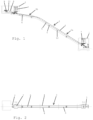
- FIG. 1 and 2 A first embodiment of a transport system according to the invention is shown, which is arranged, for example, on the slope of a mountain or hill.
- the transport system has a valley station 1 and a mountain station 2, which are connected to one another via a roadway 3.
- the roadway 3 has two parallel rails 4 which are mounted on a roadway support 5.
- the carriageway support 5 is mounted on the slope via foundations 6.
- a single vehicle 7 can be moved on the roadway 3 or its rails 4, but for representational reasons it is shown in both the valley station 1 and the mountain station 2.
- the vehicle 7 is pulled by means of a rope 8, which is driven on and unwound on a rope pulley 11 by a motor 9 arranged in the mountain station 2.
- the drive can also be located on the vehicle itself. In particular, it is also possible to use a drive system like that of a known rack railway.
- the roadway 3 has two sections 3a, 3b, with the lower section 3a having a greater gradient than the upper section 3b.
- a guideway 12 runs along the rails 4 on at least one side of the roadway 3. The distance of the guideway 12 from the rail(s) 4, more precisely from the running surface of the rails 4, is different in the two sections 3a and 3b, whereby In the illustrated embodiment, the guide track 12 is arranged essentially below one of the two rails 4. In a preferred embodiment, the lower edge or underside of the rail 4 serves as a guide track 12.
- the guide track 12 can also be a separate rail that is mounted at a suitable location.
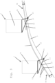
- Fig. 3 The arrangement for level control of the vehicle 7 of the embodiment of Fig. 1 and 2 is in Fig. 3 shown schematically in simplified form.
- FIG. 3 It can be seen more precisely that in the lower section 3a of the roadway 3 the distance A of the guideway or guide rail 12 from the rail 4 is larger than in section 3b.
- a guide roller 13 runs on the guide rail 12.
- the vehicle 7 has a means of transport 14, for example a cabin for transporting people and/or a container for transporting goods, and a chassis 15.
- the chassis 15 runs on the rails 4 via chassis rollers 16.
- the guide roller 13 is mounted at one end of a lever 17, which is mounted on the chassis 15 in its central region via a pivot bearing 18. With its end opposite the guide roller 13, the lever 17 is attached to the frame 19 of the transport means 14. The lever 17, and thus also the guide roller 13 mounted on it, is further connected directly to the frame 19 of the transport means 14 via a connecting element 21.
- Fig. 3 can be seen in which the vehicle 7 is shown both on the lower section 3a and on the upper section 3b.
- the means of transport 14 is always in the same horizontal orientation by being pivoted about the pivot bearing 18 relative to the chassis 15 because the distance A between the guide rail 12 and the rail 4 changes.
- the control device is arranged on both sides next to the vehicle 7.
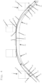
- the roadway is designed in the shape of a bridge or arch
- the roadway support 5 can be, for example, a truss, a solid reinforced concrete support, a hollow support or a combination of these or other known designs.
- the roadway 3 has three sections 3a, 3b, and 3c, which have different gradients.
- the first section 3a has, for example, a constant, positive slope with an angle of approximately +45°
- the second or middle section 3b has a slope with an angle of 0°
- the third section 3c has a negative slope with an angle of -45 ° on.
- Continuous, arcuate transitions or sections 3d, 3e are provided between these three sections 3a, 3b, 3c.
- the guide rails 4 define this course of the roadway 3.
- 4 guide tracks or guide rails 22, 23 are arranged laterally next to or outside the rails, one guide rail 22 being assigned to the first section 3a and the second guide rail 23 to the third section 3c. In the middle section 3b, the guide rails 22, 23 overlap in terms of their longitudinal extent.
- the guide rails 22, 23 can in principle be arranged on the same side of the roadway 3, in which case they are then, as in Fig. 4 shown, lie one above the other in the middle section 3b.
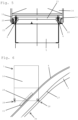
- the guide rails 22, 23 can also lie on opposite sides of the roadway 3, in which case they are in the middle section 3b, as in Fig. 5 shown schematically, can also be at the same height.
- the vehicle 7 has, as in the embodiment of Fig. 1 to 3 , a chassis 15 which rolls on the rails 4 via chassis rollers 16.
- the means of transport 14 is pivotally mounted directly on the chassis 15 via a pivot bearing 24.
- the transport means 14 has two guide rollers 25, 26, one guide roller 25 being assigned to the guide rail 22 and the other guide roller 26 to the guide rail 23.
- the guide roller 25 When the vehicle 7 is in section 3a, the guide roller 25 is in engagement with the guide rail 22, where the distance A between the guide rail 22 and the rail 4 is also large due to the large gradient of the section 3a. As the vehicle 7 approaches the middle section 3b, the gradient of the roadway 3 decreases continuously, as does the distance A between the guide rail 22 and the rail 4. In the middle area 3b, the guide rail 22 finally crosses the rail 4. This allows the level or the horizontal orientation of the means of transport 14 are kept constant.
- the guide rails 22, 23 overlap at a length that is greater than the distance between the guide rollers 25, 26 measured in the direction of travel.
- the guide roller 25 is therefore still in engagement with the guide rail 22 when the guide roller 26 comes into engagement with the guide rail 23. Only then does the guide roller 25 leave the guide rail 22.
- the level control of the means of transport is subsequently taken over by the guide rail 23 and the guide roller 26, the distance A between the guide rail 23 and the rail 4 increasing to the extent that the slope of the career 3 increases negatively.
- Fig. 6 essentially corresponds to that of Fig. 4 and 5 , however instead of the U-shaped guide rails is the Fig. 4 and 5 a flat guide rail 27 is provided, which is accommodated in a pair of guide rollers 28.
Landscapes
- Engineering & Computer Science (AREA)
- Transportation (AREA)
- Mechanical Engineering (AREA)
- Platform Screen Doors And Railroad Systems (AREA)
Claims (15)
- Système de transport avec au moins un véhicule (7) qui comprend un moyen de transport (14), en particulier une cabine, un train de roulement (15) et des rails (4), dans lequel le train de roulement (15) roule par l'intermédiaire de roues de train de roulement (16) sur une voie de circulation (3) formée par les rails (4) et le véhicule (7) peut ainsi être déplacé le long de la voie de circulation (3), laquelle voie de circulation (3) présente au moins deux sections (3a à 3d) d'inclinaison différente, dans lequel le moyen de transport (14) étant monté sur le train de roulement (15) de manière mobile dans le sens vertical et pivotante (24), dans lequel une voie de guidage s'étendant le long de la voie de circulation (3) et présente, dans des sections (3a à 3e), une distance différente de la voie de circulation (3), dans lequel un dispositif de guidage est guidé le long de la voie de guidage et dans lequel le moyen de transport (14) est relié au dispositif de guidage en vue de la régulation du niveau, afin que le niveau respectivement l'orientation horizontale du moyen de transport (14) soient maintenus constants, caractérisé en ce que la voie de guidage présente au moins un rail de guidage (12, 22, 23, 27) disposé sensiblement en dessous de l'un des rails (4) ou passe sur l'arête inférieure respectivement la face inférieure d'un rail (4).
- Système de transport selon la revendication 1, caractérisé en ce que le dispositif de guidage est disposé sur le moyen de transport (14) et présente de préférence au moins une roue de guidage (13, 25, 26, 28) ou un patin de glissement.
- Système de transport selon la revendication 1 ou 2, caractérisé en ce que le moyen de transport (14) est relié au dispositif de guidage par un dispositif de commande, de préférence mécanique.
- Système de transport selon la revendication 3, caractérisé en ce que le dispositif de commande comporte un système de leviers.
- Système de transport selon la revendication 4, caractérisé en ce que le moyen de transport (14) est supporté sur le train de roulement (15) par l'intermédiaire d'un levier (17) et en ce que le dispositif de guidage est disposé sur le levier (17).
- Système de transport selon la revendication 5, caractérisé en ce que le moyen de transport (14) est relié au dispositif de guidage au moyen d'un élément de liaison.
- Système de transport selon l'une des revendications 1 à 6, caractérisé en ce que la voie de circulation (3) présente une inclinaison aussi bien positive que négative.
- Système de transport selon la revendication 7, caractérisé en ce que sont prévus deux dispositifs de guidage, qui sont guidés alternativement le long de la voie de guidage.
- Système de transport selon la revendication 8, caractérisé en ce que les dispositifs de guidage peuvent être mis en prise avec la voie de guidage et dégagés de celle-ci.
- Système de transport selon la revendication 8, caractérisé en ce que sont prévues deux voies de guidage le long de chacune desquelles un dispositif de guidage est guidé.
- Système de transport selon la revendication 10, caractérisé en ce que les voies de guidage se chevauchent dans une zone de transition.
- Système de transport selon l'une des revendications 1 à 11, caractérisé en ce que la voie de circulation (3) est incurvée en arc de cercle au moins dans certaines sections (3d, 3e).
- Système de transport selon l'une des revendications 1 à 12, caractérisé en ce qu'il comporte un support de voie de circulation (5) avec deux sections (3a, 3c, 3d, 3e) inclinées l'une par rapport à l'autre sensiblement en forme de A.
- Système de transport selon la revendication 13, caractérisé en ce qu'au moins une des sections inclinées (3d, 3e) est en forme d'arc de cercle.
- Système de transport selon l'une des revendications 1 à 14, caractérisé en ce que le véhicule (7) est tracté par câble ou est un chemin de fer à crémaillère.
Applications Claiming Priority (2)
| Application Number | Priority Date | Filing Date | Title |
|---|---|---|---|
| ATA568/2016A AT519537A1 (de) | 2016-12-15 | 2016-12-15 | Transportsystem mit einem seilgezogenen Fahrzeug |
| PCT/EP2017/081545 WO2018108634A1 (fr) | 2016-12-15 | 2017-12-05 | Système de transport comprenant un véhicule tracté par câble |
Publications (4)
| Publication Number | Publication Date |
|---|---|
| EP3554912A1 EP3554912A1 (fr) | 2019-10-23 |
| EP3554912C0 EP3554912C0 (fr) | 2023-07-12 |
| EP3554912B1 EP3554912B1 (fr) | 2023-07-12 |
| EP3554912B9 true EP3554912B9 (fr) | 2023-10-04 |
Family
ID=60574617
Family Applications (1)
| Application Number | Title | Priority Date | Filing Date |
|---|---|---|---|
| EP17808932.2A Active EP3554912B9 (fr) | 2016-12-15 | 2017-12-05 | Système de transport comprenant un véhicule tracté par câble |
Country Status (3)
| Country | Link |
|---|---|
| EP (1) | EP3554912B9 (fr) |
| AT (1) | AT519537A1 (fr) |
| WO (1) | WO2018108634A1 (fr) |
Families Citing this family (1)
| Publication number | Priority date | Publication date | Assignee | Title |
|---|---|---|---|---|
| CN109279291B (zh) * | 2018-12-05 | 2020-10-27 | 龙南格林园艺制品有限公司 | 一种山地轨道运输系统 |
Family Cites Families (8)
| Publication number | Priority date | Publication date | Assignee | Title |
|---|---|---|---|---|
| FR1405060A (fr) * | 1964-08-25 | 1965-07-02 | Inventio Ag | Dispositif de sécurité pour transporteurs de paniers à roulettes |
| SU1096145A1 (ru) * | 1981-12-21 | 1984-06-07 | Специализированное Конструкторское Бюро Эскалаторостроения | Наклонный подъемник |
| FR2603852B3 (fr) * | 1986-09-11 | 1989-08-18 | Giauffret Georges | Funiculaire pour pente variable dont les roues aval et amont roulent sur des rails independants dans leur pente et leur ecartement et son dispositif de freinage a centrifuge |
| CH681613A5 (en) * | 1990-03-02 | 1993-04-30 | Von Roll Transportsysteme | Railway for track of varying inclination - has regulating body with drive between vehicle body and chassis, and roller, moving on track |
| CH683167A5 (fr) * | 1990-05-18 | 1994-01-31 | Rodolphe Nieth | Installation de transport. |
| FI961810A0 (fi) * | 1996-01-03 | 1996-04-26 | Valmet Corp | Anordning foer transport av pappersrullar |
| JP6124525B2 (ja) * | 2012-07-18 | 2017-05-10 | 日本ケーブル株式会社 | 索条牽引式輸送設備の救助運転装置 |
| CN107580584B (zh) * | 2015-05-06 | 2021-03-19 | 奥的斯电梯公司 | 包括悬臂的用于人员输送机的踏板元件 |
-
2016
- 2016-12-15 AT ATA568/2016A patent/AT519537A1/de not_active Application Discontinuation
-
2017
- 2017-12-05 WO PCT/EP2017/081545 patent/WO2018108634A1/fr not_active Ceased
- 2017-12-05 EP EP17808932.2A patent/EP3554912B9/fr active Active
Also Published As
| Publication number | Publication date |
|---|---|
| EP3554912C0 (fr) | 2023-07-12 |
| WO2018108634A1 (fr) | 2018-06-21 |
| AT519537A1 (de) | 2018-07-15 |
| EP3554912B1 (fr) | 2023-07-12 |
| EP3554912A1 (fr) | 2019-10-23 |
Similar Documents
| Publication | Publication Date | Title |
|---|---|---|
| DE60201341T2 (de) | Hochbahn | |
| DE3206630C2 (fr) | ||
| EP1840072B1 (fr) | Grue dotée d'un bras et d'une bande de déroulement pour les chariots porte câbles | |
| DE1104985B (de) | Rollplattenvorrichtung zum Schliessen von OEffnungen oben offener Raeume ortsfester oder beweglicher Anlagen in Fahrzeugen | |
| DE19816768C2 (de) | Vorrichtung zum Transportieren von Achterbahnwagen | |
| EP4061686B1 (fr) | Équipement de transfert pour chariots automoteurs sur un réseau similaire à un chemin de fer surélevé | |
| WO2024052523A1 (fr) | Dispositif d'aiguillage passif pour un système de trafic ferroviaire, bogie pour un système de trafic ferroviaire et système de trafic ferroviaire | |
| DE102011002334A1 (de) | Strohmabnehmersystem für ein Fahrzeug | |
| EP3554912B1 (fr) | Système de transport comprenant un véhicule tracté par câble | |
| DE3522918A1 (de) | Vorrichtung fuer den transport eines gleisabschnittes oder einer montierten gleisverbindung auf dem schienenwege | |
| DE202010008641U1 (de) | Vorrichtung zum Transport von Fahrzeugen einer spurgeführten Vergnügungsbahn | |
| DE2228196C3 (de) | Einrichtung zum Auswechseln von Gleisjochen | |
| DE2910867A1 (de) | Transportsystem | |
| DE1405561A1 (de) | Schraegaufzug | |
| EP1834042B1 (fr) | Machine servant a remettre en etat une voie ferree | |
| DE655748C (de) | Verlegbare Schiebebuehne fuer Foerderwagen im Grubenbetrieb | |
| EP3699121B1 (fr) | Système d'accès pour une voiture-citerne ferroviaire, voiture de déplacement et procédé de fourniture d'un accès | |
| DE3340739A1 (de) | Gleisbaumaschine fuer das auswechseln eines montierten gleisabschnitts oder einer montierten gleisverbindung | |
| DE3719778C1 (en) | Apparatus for transporting and laying beam-like supports made of steel, reinforced or prestressed concrete | |
| DE3340737A1 (de) | Gleisbaumaschine zum greifen und tragen von montierten gleisabschnitten und/oder gleisverbindungen | |
| EP1467024B1 (fr) | Dispositif pour déposer des rails dans la voie ferrée | |
| DE4237802C1 (en) | Self chain driven transport system - comprises vehicle units set at intervals on supports with locators for rollers over which runs motor driven chain drive to pull vehicle | |
| DE850795C (de) | Portalartige Vorrichtung zum Heben, Verfahren und Absetzen von Lasten | |
| DE217727C (fr) | ||
| DE3343618A1 (de) | Gleisbaumaschine zum ausraeumen und planieren des schotters |
Legal Events
| Date | Code | Title | Description |
|---|---|---|---|
| STAA | Information on the status of an ep patent application or granted ep patent |
Free format text: STATUS: UNKNOWN |
|
| STAA | Information on the status of an ep patent application or granted ep patent |
Free format text: STATUS: THE INTERNATIONAL PUBLICATION HAS BEEN MADE |
|
| PUAI | Public reference made under article 153(3) epc to a published international application that has entered the european phase |
Free format text: ORIGINAL CODE: 0009012 |
|
| STAA | Information on the status of an ep patent application or granted ep patent |
Free format text: STATUS: REQUEST FOR EXAMINATION WAS MADE |
|
| 17P | Request for examination filed |
Effective date: 20190712 |
|
| AK | Designated contracting states |
Kind code of ref document: A1 Designated state(s): AL AT BE BG CH CY CZ DE DK EE ES FI FR GB GR HR HU IE IS IT LI LT LU LV MC MK MT NL NO PL PT RO RS SE SI SK SM TR |
|
| AX | Request for extension of the european patent |
Extension state: BA ME |
|
| DAV | Request for validation of the european patent (deleted) | ||
| DAX | Request for extension of the european patent (deleted) | ||
| STAA | Information on the status of an ep patent application or granted ep patent |
Free format text: STATUS: EXAMINATION IS IN PROGRESS |
|
| 17Q | First examination report despatched |
Effective date: 20211223 |
|
| GRAP | Despatch of communication of intention to grant a patent |
Free format text: ORIGINAL CODE: EPIDOSNIGR1 |
|
| STAA | Information on the status of an ep patent application or granted ep patent |
Free format text: STATUS: GRANT OF PATENT IS INTENDED |
|
| INTG | Intention to grant announced |
Effective date: 20230203 |
|
| GRAS | Grant fee paid |
Free format text: ORIGINAL CODE: EPIDOSNIGR3 |
|
| GRAA | (expected) grant |
Free format text: ORIGINAL CODE: 0009210 |
|
| STAA | Information on the status of an ep patent application or granted ep patent |
Free format text: STATUS: THE PATENT HAS BEEN GRANTED |
|
| AK | Designated contracting states |
Kind code of ref document: B1 Designated state(s): AL AT BE BG CH CY CZ DE DK EE ES FI FR GB GR HR HU IE IS IT LI LT LU LV MC MK MT NL NO PL PT RO RS SE SI SK SM TR |
|
| REG | Reference to a national code |
Ref country code: CH Ref legal event code: EP |
|
| REG | Reference to a national code |
Ref country code: DE Ref legal event code: R096 Ref document number: 502017015057 Country of ref document: DE |
|
| REG | Reference to a national code |
Ref country code: IE Ref legal event code: FG4D Free format text: LANGUAGE OF EP DOCUMENT: GERMAN |
|
| U01 | Request for unitary effect filed |
Effective date: 20230726 |
|
| U07 | Unitary effect registered |
Designated state(s): AT BE BG DE DK EE FI FR IT LT LU LV MT NL PT SE SI Effective date: 20230801 |
|
| REG | Reference to a national code |
Ref country code: CH Ref legal event code: PK Free format text: BERICHTIGUNG B9 |
|
| REG | Reference to a national code |
Ref country code: LT Ref legal event code: MG9D |
|
| U20 | Renewal fee for the european patent with unitary effect paid |
Year of fee payment: 7 Effective date: 20231214 |
|
| PG25 | Lapsed in a contracting state [announced via postgrant information from national office to epo] |
Ref country code: GR Free format text: LAPSE BECAUSE OF FAILURE TO SUBMIT A TRANSLATION OF THE DESCRIPTION OR TO PAY THE FEE WITHIN THE PRESCRIBED TIME-LIMIT Effective date: 20231013 |
|
| PG25 | Lapsed in a contracting state [announced via postgrant information from national office to epo] |
Ref country code: ES Free format text: LAPSE BECAUSE OF FAILURE TO SUBMIT A TRANSLATION OF THE DESCRIPTION OR TO PAY THE FEE WITHIN THE PRESCRIBED TIME-LIMIT Effective date: 20230712 |
|
| PG25 | Lapsed in a contracting state [announced via postgrant information from national office to epo] |
Ref country code: IS Free format text: LAPSE BECAUSE OF FAILURE TO SUBMIT A TRANSLATION OF THE DESCRIPTION OR TO PAY THE FEE WITHIN THE PRESCRIBED TIME-LIMIT Effective date: 20231112 |
|
| PG25 | Lapsed in a contracting state [announced via postgrant information from national office to epo] |
Ref country code: RS Free format text: LAPSE BECAUSE OF FAILURE TO SUBMIT A TRANSLATION OF THE DESCRIPTION OR TO PAY THE FEE WITHIN THE PRESCRIBED TIME-LIMIT Effective date: 20230712 Ref country code: NO Free format text: LAPSE BECAUSE OF FAILURE TO SUBMIT A TRANSLATION OF THE DESCRIPTION OR TO PAY THE FEE WITHIN THE PRESCRIBED TIME-LIMIT Effective date: 20231012 Ref country code: IS Free format text: LAPSE BECAUSE OF FAILURE TO SUBMIT A TRANSLATION OF THE DESCRIPTION OR TO PAY THE FEE WITHIN THE PRESCRIBED TIME-LIMIT Effective date: 20231112 Ref country code: HR Free format text: LAPSE BECAUSE OF FAILURE TO SUBMIT A TRANSLATION OF THE DESCRIPTION OR TO PAY THE FEE WITHIN THE PRESCRIBED TIME-LIMIT Effective date: 20230712 Ref country code: GR Free format text: LAPSE BECAUSE OF FAILURE TO SUBMIT A TRANSLATION OF THE DESCRIPTION OR TO PAY THE FEE WITHIN THE PRESCRIBED TIME-LIMIT Effective date: 20231013 Ref country code: ES Free format text: LAPSE BECAUSE OF FAILURE TO SUBMIT A TRANSLATION OF THE DESCRIPTION OR TO PAY THE FEE WITHIN THE PRESCRIBED TIME-LIMIT Effective date: 20230712 |
|
| PG25 | Lapsed in a contracting state [announced via postgrant information from national office to epo] |
Ref country code: PL Free format text: LAPSE BECAUSE OF FAILURE TO SUBMIT A TRANSLATION OF THE DESCRIPTION OR TO PAY THE FEE WITHIN THE PRESCRIBED TIME-LIMIT Effective date: 20230712 |
|
| REG | Reference to a national code |
Ref country code: DE Ref legal event code: R097 Ref document number: 502017015057 Country of ref document: DE |
|
| PG25 | Lapsed in a contracting state [announced via postgrant information from national office to epo] |
Ref country code: SM Free format text: LAPSE BECAUSE OF FAILURE TO SUBMIT A TRANSLATION OF THE DESCRIPTION OR TO PAY THE FEE WITHIN THE PRESCRIBED TIME-LIMIT Effective date: 20230712 Ref country code: RO Free format text: LAPSE BECAUSE OF FAILURE TO SUBMIT A TRANSLATION OF THE DESCRIPTION OR TO PAY THE FEE WITHIN THE PRESCRIBED TIME-LIMIT Effective date: 20230712 Ref country code: CZ Free format text: LAPSE BECAUSE OF FAILURE TO SUBMIT A TRANSLATION OF THE DESCRIPTION OR TO PAY THE FEE WITHIN THE PRESCRIBED TIME-LIMIT Effective date: 20230712 Ref country code: SK Free format text: LAPSE BECAUSE OF FAILURE TO SUBMIT A TRANSLATION OF THE DESCRIPTION OR TO PAY THE FEE WITHIN THE PRESCRIBED TIME-LIMIT Effective date: 20230712 |
|
| PLBE | No opposition filed within time limit |
Free format text: ORIGINAL CODE: 0009261 |
|
| STAA | Information on the status of an ep patent application or granted ep patent |
Free format text: STATUS: NO OPPOSITION FILED WITHIN TIME LIMIT |
|
| 26N | No opposition filed |
Effective date: 20240415 |
|
| REG | Reference to a national code |
Ref country code: CH Ref legal event code: PL |
|
| PG25 | Lapsed in a contracting state [announced via postgrant information from national office to epo] |
Ref country code: MC Free format text: LAPSE BECAUSE OF FAILURE TO SUBMIT A TRANSLATION OF THE DESCRIPTION OR TO PAY THE FEE WITHIN THE PRESCRIBED TIME-LIMIT Effective date: 20230712 |
|
| GBPC | Gb: european patent ceased through non-payment of renewal fee |
Effective date: 20231205 |
|
| PG25 | Lapsed in a contracting state [announced via postgrant information from national office to epo] |
Ref country code: MC Free format text: LAPSE BECAUSE OF FAILURE TO SUBMIT A TRANSLATION OF THE DESCRIPTION OR TO PAY THE FEE WITHIN THE PRESCRIBED TIME-LIMIT Effective date: 20230712 |
|
| REG | Reference to a national code |
Ref country code: IE Ref legal event code: MM4A |
|
| PG25 | Lapsed in a contracting state [announced via postgrant information from national office to epo] |
Ref country code: IE Free format text: LAPSE BECAUSE OF NON-PAYMENT OF DUE FEES Effective date: 20231205 |
|
| PG25 | Lapsed in a contracting state [announced via postgrant information from national office to epo] |
Ref country code: GB Free format text: LAPSE BECAUSE OF NON-PAYMENT OF DUE FEES Effective date: 20231205 |
|
| PG25 | Lapsed in a contracting state [announced via postgrant information from national office to epo] |
Ref country code: CH Free format text: LAPSE BECAUSE OF NON-PAYMENT OF DUE FEES Effective date: 20231231 |
|
| PG25 | Lapsed in a contracting state [announced via postgrant information from national office to epo] |
Ref country code: IE Free format text: LAPSE BECAUSE OF NON-PAYMENT OF DUE FEES Effective date: 20231205 Ref country code: GB Free format text: LAPSE BECAUSE OF NON-PAYMENT OF DUE FEES Effective date: 20231205 Ref country code: CH Free format text: LAPSE BECAUSE OF NON-PAYMENT OF DUE FEES Effective date: 20231231 |
|
| U20 | Renewal fee for the european patent with unitary effect paid |
Year of fee payment: 8 Effective date: 20241227 |
|
| PG25 | Lapsed in a contracting state [announced via postgrant information from national office to epo] |
Ref country code: CY Free format text: LAPSE BECAUSE OF FAILURE TO SUBMIT A TRANSLATION OF THE DESCRIPTION OR TO PAY THE FEE WITHIN THE PRESCRIBED TIME-LIMIT; INVALID AB INITIO Effective date: 20171205 |
|
| PG25 | Lapsed in a contracting state [announced via postgrant information from national office to epo] |
Ref country code: HU Free format text: LAPSE BECAUSE OF FAILURE TO SUBMIT A TRANSLATION OF THE DESCRIPTION OR TO PAY THE FEE WITHIN THE PRESCRIBED TIME-LIMIT; INVALID AB INITIO Effective date: 20171205 |
|
| PG25 | Lapsed in a contracting state [announced via postgrant information from national office to epo] |
Ref country code: TR Free format text: LAPSE BECAUSE OF FAILURE TO SUBMIT A TRANSLATION OF THE DESCRIPTION OR TO PAY THE FEE WITHIN THE PRESCRIBED TIME-LIMIT Effective date: 20230712 |
|
| U20 | Renewal fee for the european patent with unitary effect paid |
Year of fee payment: 9 Effective date: 20251204 |