EP3554975B1 - Système de transport sûr - Google Patents
Système de transport sûr Download PDFInfo
- Publication number
- EP3554975B1 EP3554975B1 EP17798183.4A EP17798183A EP3554975B1 EP 3554975 B1 EP3554975 B1 EP 3554975B1 EP 17798183 A EP17798183 A EP 17798183A EP 3554975 B1 EP3554975 B1 EP 3554975B1
- Authority
- EP
- European Patent Office
- Prior art keywords
- housing element
- transport
- plane
- openings
- linear conveyor
- Prior art date
- Legal status (The legal status is an assumption and is not a legal conclusion. Google has not performed a legal analysis and makes no representation as to the accuracy of the status listed.)
- Active
Links
Images


Classifications
-
- B—PERFORMING OPERATIONS; TRANSPORTING
- B65—CONVEYING; PACKING; STORING; HANDLING THIN OR FILAMENTARY MATERIAL
- B65G—TRANSPORT OR STORAGE DEVICES, e.g. CONVEYORS FOR LOADING OR TIPPING, SHOP CONVEYOR SYSTEMS OR PNEUMATIC TUBE CONVEYORS
- B65G37/00—Combinations of mechanical conveyors of the same kind, or of different kinds, of interest apart from their application in particular machines or use in particular manufacturing processes
-
- B—PERFORMING OPERATIONS; TRANSPORTING
- B65—CONVEYING; PACKING; STORING; HANDLING THIN OR FILAMENTARY MATERIAL
- B65G—TRANSPORT OR STORAGE DEVICES, e.g. CONVEYORS FOR LOADING OR TIPPING, SHOP CONVEYOR SYSTEMS OR PNEUMATIC TUBE CONVEYORS
- B65G15/00—Conveyors having endless load-conveying surfaces, i.e. belts and like continuous members, to which tractive effort is transmitted by means other than endless driving elements of similar configuration
- B65G15/22—Conveyors having endless load-conveying surfaces, i.e. belts and like continuous members, to which tractive effort is transmitted by means other than endless driving elements of similar configuration comprising a series of co-operating units
-
- B—PERFORMING OPERATIONS; TRANSPORTING
- B65—CONVEYING; PACKING; STORING; HANDLING THIN OR FILAMENTARY MATERIAL
- B65G—TRANSPORT OR STORAGE DEVICES, e.g. CONVEYORS FOR LOADING OR TIPPING, SHOP CONVEYOR SYSTEMS OR PNEUMATIC TUBE CONVEYORS
- B65G21/00—Supporting or protective framework or housings for endless load-carriers or traction elements of belt or chain conveyors
- B65G21/10—Supporting or protective framework or housings for endless load-carriers or traction elements of belt or chain conveyors movable, or having interchangeable or relatively movable parts; Devices for moving framework or parts thereof
-
- B—PERFORMING OPERATIONS; TRANSPORTING
- B65—CONVEYING; PACKING; STORING; HANDLING THIN OR FILAMENTARY MATERIAL
- B65G—TRANSPORT OR STORAGE DEVICES, e.g. CONVEYORS FOR LOADING OR TIPPING, SHOP CONVEYOR SYSTEMS OR PNEUMATIC TUBE CONVEYORS
- B65G35/00—Mechanical conveyors not otherwise provided for
- B65G35/06—Mechanical conveyors not otherwise provided for comprising a load-carrier moving along a path, e.g. a closed path, and adapted to be engaged by any one of a series of traction elements spaced along the path
-
- B—PERFORMING OPERATIONS; TRANSPORTING
- B65—CONVEYING; PACKING; STORING; HANDLING THIN OR FILAMENTARY MATERIAL
- B65G—TRANSPORT OR STORAGE DEVICES, e.g. CONVEYORS FOR LOADING OR TIPPING, SHOP CONVEYOR SYSTEMS OR PNEUMATIC TUBE CONVEYORS
- B65G47/00—Article or material-handling devices associated with conveyors; Methods employing such devices
- B65G47/52—Devices for transferring articles or materials between conveyors i.e. discharging or feeding devices
- B65G47/64—Switching conveyors
- B65G47/644—Switching conveyors by a pivoting displacement of the switching conveyor
- B65G47/648—Switching conveyors by a pivoting displacement of the switching conveyor about a vertical axis
Definitions
- the invention relates to a conveying device for transport containers for spectacle lenses, with a transport table which has a round transport surface and a transport drive for conveying the transport containers in a horizontal transport direction along the transport surface, and with a rotary drive for rotating the transport table about a vertical axis (A).
- a corresponding conveyor device which is designed as a turntable, is available from Alztec, http://www.alztec.com/fanische.php.
- This turntable is walkable and designed for the conveyance of pallets and therefore has relatively large dimensions. It is used in combination with roller conveyors and has potential danger points in the edge area, i.e. in the area of the connection of the roller conveyors and in the area of the conveyor rollers, where there is a risk of injury from crushing or shearing a hand or a finger.
- Rotary tables for pallets are also available from kardexmlog, http://www.kardexmlog.de/de/products-mlog/foerdertechnik/umsetzer.html. These turntables are used for the corner transfer of pallets.
- the EP 1 947 035 A1 shows a sorting device for roller conveyors with a sorting table having a square sorting surface. This sorting area consists of a large number of small turntables that can be rotated to change the conveying direction.
- DIN EN 349: 1993 + A1: 2008 specifies minimum distances to avoid crushing body parts.
- DIN EN ISO 13857: 2008 specifies safety clearances against reaching hazardous areas with the upper and lower limbs.
- the space required or the space required should preferably be as small as possible. In addition, use under clean or gray room conditions should also be possible.
- an NxM matrix comprising conveyor devices with the features of claim 1 or the use of one of these conveyor devices in such a matrix with the features of claim 2 or a conveyor device with the features of claim 3.
- the conveyor device according to the invention for a transport container for spectacle lenses comprises a linear conveyor unit for conveying the transport container in a straight line and a rotating unit for rotating the linear conveyor unit.
- rotating the linear conveyor unit means the realignment of the linear conveyor unit for conveying the transport container in a different rectilinear direction that deviates from the original rectilinear direction.
- the rotating unit is arranged in a housing.
- This housing includes a one-level and when rotating the Linear conveyor unit is spaced from the plane by one or more gaps with assigned gap dimensions.
- the gap dimensions of all gaps are less than or equal to 5 mm. Furthermore, it is provided according to the invention that the first housing element has a plurality of second openings penetrating the plane with assigned opening widths, which are all less than or equal to 5 mm.
- a virtually completely covered level is created, which represents effective protection against contact.
- a user is reliably prevented from accidentally reaching into a gap or into an opening and thereby possibly suffering from crushing or shearing.
- the suitability of the conveying device for transport containers for spectacle lenses means that relatively small transport containers with a width of less than 40 cm and a length of less than 50 cm can be transported reliably.
- the gap dimension means a distance between adjacent and adjacent components.
- Such components can be a component of the linear conveyor unit or components of the housing. It can also be the distance between the plane and adjacent components, such as a fixed housing wall of the conveyor.
- openings are e.g. Round or square recesses or recesses, which are arranged for example in the plane and can serve to reduce the weight of the mass to be moved.
- a plane is understood to mean a flat surface along which the transport containers are transported.
- the level can be formed as part of a plate serving as a housing element made of a metal or plastic or a perforated plate.
- the housing element is preferably held on a transport table, for example detachably.
- the level can be designed as the surface of the transport table and serve to support the transport containers to be transported from below or to prevent the transport containers from tipping over. When turning the Transport table, the housing element held by the transport table is also moved.
- the invention consists in that there is a stationary circular cylindrical second housing element enclosing the rotating unit, which does not rotate when the linear conveyor unit is rotated, and that the plane of the rotating first housing element when the linear conveyor unit is rotating is located within the stationary second housing element and is complementary in shape is formed to the fixed second housing element.
- the plane of the first housing element rotating when the linear conveyor unit rotates is preferably spaced apart from the fixed second housing element by a gap with a gap dimension which is less than or equal to 5 mm. This ensures protection against accidental contact.
- the plane is arranged in or directly on a stationary, in particular vertically running, cylinder.
- the fixed cylinder forms an outer side or outer wall of the conveyor device. Due to the fixed cylinder, the conveyor device has no moving parts on its outer wall, so that there is no danger of crushing or shearing for operating personnel at this point.
- the gap dimension between the plane forming a transport surface and the cylinder is less than or equal to 5 mm in order to provide an operator with protection against intervention.
- the cylinder therefore has a diameter which essentially corresponds to the diameter of the transport surface. Together with the transport surface, the cylinder forms a protection against accidental contact and prevents unintentional contact of these drive components, and avoids dangerous crushing or shearing points in order to protect operating personnel.
- the cylinder therefore forms a housing together with the plane forming the transport surface.
- the plane representing the transport surface forms a quasi-closed surface for the operating personnel through the openings with a diameter or a clear width of less than or equal to 5 mm and closes off the top of the cylinder.
- Potentially dangerous components such as rotating rollers or rotating drive belts thereby secured against unintentional and dangerous contact by operating personnel.
- the outer dimensions of the cylinder form the maximum interference contour of the conveyor. I.e. a possible danger area of the conveyor is limited to the dimensions of the cylinder.
- the components comprised by the rotary unit and the linear conveyor unit are arranged within the housing or protrude less than 5 mm beyond the housing.
- the driven components of the conveying device can thus be accommodated within the housing formed by the cylinder and transport surface or project 5 mm or less beyond the housing. This on the one hand reduces the installation space required and on the other hand reduces the risk of crushing or shearing points.
- the conveyor device is designed for the transport of smaller transport containers, the dimensions of which generally do not exceed 50 cm in length and 40 cm in width.
- Optical components for example lenses for spectacle lenses, spectacle frames or other small parts, can be transported in the transport containers.
- the diameter of the cylinder or the diameter of the transport surface is less than 60 cm, preferably 50 cm or 40 cm or also 30 cm or less in order to efficiently transport containers with small dimensions, that is to say on a small footprint transport.
- the linear conveyor unit is used in particular for the automatically driven transport of a transport container along a predetermined flow.
- a flow consists of several transport containers arranged in succession at a distance.
- the transport direction is changed in a preferably horizontal plane by means of the rotating unit, in that the rotating unit rotates the transport table or the transport surface about an axis, in particular in the case of a horizontal arrangement of the plane about a vertical axis.
- the rotary unit can rotate the linear feed unit by any angle.
- the rotating unit has a servo motor or a stepper motor, which is controlled by a control device to set a desired angle. It is thus possible to discharge individual transport containers from a continuous flow or to feed them into a second flow. Since any angle can be set by the turntable, not only can it be discharged transversely to the flow, but different directions can be selected. It is therefore also possible to branch the delivery flow into several partial flows.
- the cylinder forms a circular cylinder.
- the transport surface forms the top of the cylinder and is circular.
- the round transport surface closes the stationary cylinder at the top, so that the cylinder together with the transport surface forms a housing which is at least closed at the top.
- the longitudinal axis of the cylinder preferably runs in the vertical direction.
- the cylinder is hollow on the inside and therefore forms an interior space for accommodating components of the conveying device.
- the cylinder can have a base which carries the cylinder itself or the individual components of the conveyor.
- a frame with height-adjustable feet can be provided, which serves as a mechanically stable and height-adjustable holder in order to carry the conveyor or the base.
- the conveyor device can thus be arranged directly adjacent to an end or a start of a conveyor belt.
- the rotating unit is arranged entirely within the closed housing. Driven or moving parts, where there is a risk of being crushed, are therefore completely arranged inside the cylinder or the closed housing and thus for operating personnel outside the danger area.
- the outer edge of the plane forming the transport surface has a closed, circular course and a central region of the transport surface is designed as a grid surface with round or angular openings, in particular recesses.
- the dimensions of the openings, in particular of the recesses are preferably less than or equal to 5 mm in diameter or clear width, preferably less than or equal to 4 mm.
- the conveyor device is used in a clean room or gray room.
- a clean room is a room in which disturbing particles in the air are kept as low as possible by special cleaning measures.
- Clean rooms are used in manufacturing processes prone to contamination, for example in the production of optical devices or optical components or in the production of germ-free food.
- a gray room differs from a clean room in that it requires less air.
- the conveying device can be flushed with cleaned air.
- the openings in the plane are dimensioned in such a way and their number is defined in such a way that either the plane has a surface coverage of less than 60%, preferably less than 50%, in a vertical projection . Due to this relatively small surface coverage, the cylinder or the conveying device can be flushed or flushed with an air flow, in particular in a vertical direction, without causing disturbing turbulence. This makes it possible to use the conveying device also for tasks susceptible to contamination, such as for example in the production of optical devices, in particular spectacle lenses.
- the openings, in particular recesses, in the plane also reduce their mass, so that the mass of the conveying device to be moved is reduced. It is advantageous that due to the low mass the housing element providing the level, e.g. of the transport table, the rotating unit requires only relatively little force to rotate the linear feed unit. This makes it possible to get by with relatively small drive forces and to limit them to small, ie. H. The safety of the conveyor device can be further increased by non-dangerous values.
- the cylinder is designed with a self-contained outer surface.
- the self-contained outer surface of the cylinder for material reduction or weight reduction can have round or square openings or recesses whose diameter or their clear width or clear length are less than or equal to 5 mm or less than or equal to 4 mm.
- the cylinder can be formed, for example, by a circular-shaped sheet of aluminum or steel, in particular a grid sheet.
- the rotary unit can be connected to a control device.
- the control device can limit the maximum force and / or the maximum speed of the rotary drive.
- the control device can detect a jamming of the rotating unit, for example via a sensor or by monitoring the operating current of the rotary drive motor. If a jam occurs, the control device can switch off or return the rotary drive in order to eliminate the jam.
- the linear conveyor unit has a transport drive which is designed as a conveyor belt drive.
- the transport drive can have a conveyor belt which runs endlessly over two deflection rollers, the upper run of which runs above the level and the lower run of which runs below the level.
- the upper strand can be at a distance of less than or equal to 5 mm from the plane in order to minimize the risk of injury.
- the tension of the conveyor belt can be adjusted. It is provided that the distance between the two deflection rollers of a conveyor belt can be adjusted. For example, the position of a deflection roller can be changed using an adjusting screw. This makes it possible to compensate for the lengthening of a conveyor belt or tolerances of a conveyor belt that occurs in practice and to keep the tension of the conveyor belt at an optimal value.
- the conveyor belt can have two conveyor belts arranged in parallel and at a distance from one another, which are connected by a common drive shaft.
- a structurally simple construction results from the drive shaft being connected in a rotationally fixed manner to a deflection roller of a conveyor belt.
- the conveyor belt can be driven in that the transport drive has a drive motor for driving the drive shaft and either the output of the drive motor is connected to the drive shaft directly or via a transmission, in particular a gear transmission or a belt transmission.
- a transmission in particular a gear transmission or a belt transmission.
- one of the conveyor belts can have a third one Be guided pulley, which is arranged below the transport surface and driven by the drive motor.
- the transport table has two guide plates running in parallel.
- the ends of the guide plates can be bent in such a way that they each form an inlet funnel or an outlet funnel.
- the distance between the two guide plates is adapted to the maximum width of the transport container to be conveyed.
- the conveyor device can be used directly within a processing station of a production line. Due to the small dimensions of the conveyor device, it can be arranged, for example, within a CNC machine or within a grinding machine.
- the conveyor device can transport eyeglass lenses to be processed in transport containers and deliver them to or from the CNC machine or the grinding machine.
- an eyeglass lens can be removed from the transport container with a robot arm, for example, and transported to a processing station.
- spectacle lens is understood to mean an optical lens for spectacles.
- the machined part can then be returned to the transport container and transported on.
- a second conveyor device can also be provided in order to pick up and remove the parts processed by the CNC machine or grinding machine. In this way it is possible to manufacture optical lenses on a relatively small footprint.
- the conveyor device is designed as a line combiner.
- the conveying device combines individual partial flows, which are delivered from different transport directions, into a single conveying flow and conveys this further in one transport direction.
- the conveyor device is designed as a line switch. This means that the conveying device distributes a conveying flow conveyed in one transport direction over several partial flows and conveys these further in different transport directions.
- the conveyor device according to the invention is connected in practice with several units to form a larger sorting device.
- a sorting device can, for example, comprise several of the conveyor devices according to the invention, which are either connected directly to one another or interconnected by means of intermediate conveyor belts.
- several of the sorting devices can be arranged directly one after the other to form an N x M matrix.
- the individual conveying devices according to the invention can be arranged directly next to one another, since, because of the round and fixed outer contour of the cylinder, there is no risk of crushing for operating personnel in the spaces between the adjacent conveying devices.
- the fixed cylinder forms the outer contour of the conveyor.
- the stationary cylinder in the area between the conveyor devices or between the conveyor device and the feed or discharge belts does not result in any relative relation to one another moving parts, and therefore no dangerous crushing or shearing points for operating personnel.
- Such a storage device can e.g. have a holding device in order to hold the transport container at a distance above the level.
- the storage device comprises e.g. a frame with two vertically running rails, the holding device being fastened to the rails in order to hold or fix transport containers to the at least two rails.
- the frame can be connected at its lower end to the transport table or the housing element providing the level, and the holding device holds or fixes a transport container to the rails at a vertical distance above the transport table which is greater than the maximum height of a transport container to be conveyed.
- a particularly advantageous embodiment of this variant consists in that there is a circular cylindrical third housing element for the holding device, which prevents people from reaching into the holding device.
- a further embodiment of this embodiment consists in that a fourth housing element is present which closes the third housing element on the top side.
- the fourth housing element has a plurality of third openings with assigned opening widths, the opening widths of all third openings being less than or equal to 5 mm and / or the number of third openings being dimensioned such that the plane covers a surface in a vertical projection less than 60% or less than 50%.
- a lifting device can be provided which lifts a transport container from the plane forming the transport surface by a somewhat greater distance than the maximum height of a transport container to be conveyed.
- the raised transport container is then moved over the holding device, e.g. fixed to the rails.
- the storage device thus holds transport containers at a distance above the level such that the transport of moving transport containers is not impaired.
- the holding device holds or fixes transport containers on the rails at a vertical distance above the level which is greater than the maximum height of a transport container to be conveyed. So the storage device, e.g. on the rails, one or more transport containers and serves as a kind of storage or buffer for transport containers.
- the third housing element is designed as a touch guard in the form of a second, in particular vertically running, cylinder, which can be placed on the cylinder of the conveyor device forming the third housing element, the diameter of the second cylinder being the diameter of the Cylinder of the conveyor corresponds.
- the length of the second cylinder preferably corresponds at least to the length of the bearing device, in particular, for example, the frame described above, in order to form a full-surface contact protection.
- the second cylinder can be held on the frame, for example.
- the second cylinder can have openings which are provided at its lower end and are adapted to the dimensions of a transport container, in particular to its cross section.
- a transport container preferably has a lateral groove in which a guide rail of the holding device or the lifting device engages.
- the rails have a lifting drive in order to lift transport containers in the vertical direction from the transport table and / or to lower them onto the transport table.
- the lifting drive can be arranged on the transport table or on one or both rails in order to raise or lower transport containers in the vertical direction.
- transport containers can be arranged one above the other on the rails. It is thus possible for a stack held on the rails to be produced from a plurality of transport containers arranged one above the other.
- the frame can accordingly hold a stack comprising a plurality of transport containers arranged one above the other in the vertical direction.
- the holder is preferably carried out by holding or fixing at least the lowermost transport container to the vertically running rails.
- Such a stack can consist of a plurality, preferably more than five transport containers arranged one above the other. To build the stack, individual transport containers are lifted one after the other. This pushes the transport containers already in the stack up by one space.
- the stack built up on the rails can be used for short-term intermediate storage of individual transport containers or for long-term storage, i.e. serve for the storage of individual transport containers.
- the storage device is used in a production line in order to serve as an intermediate store or as a buffer for components or for raw material.
- the transport table described above has two receptacles spaced apart transversely to the transport direction for connecting the two vertical rails of the frame, each of which one of these receptacles is arranged in a region between a conveyor belt and the outer edge of the transport table and preferably connects a vertically running rail to the transport table in a detachable manner.
- the rails can be screwed to the receptacles on the transport table.
- the frame has a yoke or housing connecting the two rails on its upper side.
- the length of the rails is at least 10 cm longer than the maximum stack height of the piece goods, so that the distance between the yoke or the top of the housing and the top edge of the stack is at least 10 cm. This prevents a clamping point that is dangerous for the operating personnel from being created at the upper end of the stack.
- the distance between the vertically running rails corresponds to at least the width of the transport container to be transported. Accordingly, the length of the yoke connecting the two rails also corresponds at least to the width of the transporting transport container or the width of the transport container to be transported and additionally to the width of the rails.
- the lifting device has a first fixed part and a second part that can be driven in a vertical direction, both pivotable rails being provided on the first fixed part and on the second movable part, said rails being attached to a package or a groove arranged in a transport container cooperate to hold it.
- the rails of the fixed part are swung out.
- the rails of the movable part remain in the groove of the transport container and hold it.
- the movable part of the lifting drive is then moved vertically together with the transport containers to a position below or above.
- the rails of the fixed part of the lifting drive are swiveled in again at the new position in order to fix the transport container in the new position.
- both the rails of the fixed part and the rails of the movable part are released, so that the transport container is lowered onto the transport table.
- the transport table has a lifting device with one lifting cylinder or a plurality of lifting cylinders in order to raise or lower transport containers in the vertical direction.
- a lifting cylinder has a lifting ram on its upper side which reaches through an opening of the transport table.
- the opening is preferably dimensioned such that a gap between the stamp and the transport table is less than or equal to 5 mm or less than or equal to 4 mm in order to reduce the risk of crushing at this gap.
- the gap between the rails and the transport container held by the rails is preferably also made for the gap between the rails and the transport container held by the rails to be less than or equal to 5 mm.
- the top of the lifting ram is aligned with the transport table in the rest position of the lifting device.
- the opening of the transport table is closed by the top of the lifting plunger and an intervention in components located below the transport table is prevented for a user.
- a control device connected to the lifting device limits the speed and / or the driving force of the lifting device.
- the control device can either switch off the lifting device in the event of jamming or return a piece in order to prevent or dissolve jamming.
- the lifting device in particular the lifting cylinder, moves an individual transport container or a stack of several transport containers. It is essential that the vertical stroke of the lifting device is somewhat larger than the maximum height of a transport container to be conveyed. This means that a single transport container is lifted from the surface of the transport table and transported to a height that lies above an upper edge of the next transport container to be conveyed. In the course of this movement, the upper edge of the transport container to be lifted abuts the underside of a transport container already present on the rails. The lifting device automatically takes this along with its movement and raises it further. It is through this movement possible to form a vertical stack consisting of several individual transport containers with the lifting ram alone without an additional lifting drive.
- the lifting plunger is removed from the stack as follows: When the transport table is empty, the lifting die extends until its top lies against the underside of the stack of transport containers. The holding device is then released so that the stack rests on the lifting ram and is held by it. The lifting ram is then lowered together with the stack until the second transport container of the stack, seen from below, is lowered to the corresponding height, which lies above an upper edge of the next transport container to be conveyed. By switching on the holding device, this transport container, which now forms the lowest part of the stack, is fixed to the rails. As a result, the entire remaining stack, which is supported on the lowest transport container, is held and fixed on the rails via the holding device.
- the lifting plunger then lowers the lowest transport container further until it rests on the transport table.
- the transport table can then remove this transport container in a desired transport direction.
- the rotary drive rotates the transport table together with the storage device into the desired position.
- one embodiment can provide that the horizontal extension of the frame in the transport direction and transversely to the transport direction is less than or equal to the diameter of the transport table, preferably that the diameter of the transport table is greater than a longitudinal extension and / or transverse extension of the transport container to be conveyed.
- the conveying device or storage device according to the invention can be used in industry in the context of a distribution of individual parts or in the context of warehousing.
- the device according to the invention can also be used when transporting spare parts.
- the device according to the invention can be used in production lines to ensure the continuous flow of material from individual parts. Especially relatively small parts like optical lenses can be transported with the conveyor and / or storage device on a relatively small footprint.
- the conveying device and / or the storage device is mainly used for transport containers whose external dimensions do not exceed 50 cm in length, 40 cm in width and 35 cm in height.
- small transport containers whose dimensions are 20 cm ⁇ 10 cm ⁇ 10 cm or even less can be conveyed with the conveyor device and / or with the storage device.
- the second cylinder of the bearing device has a diameter of 30 cm or less.
- the diameter of the first cylinder and / or the second cylinder defines the maximum interference contour of the bearing device.
- transport containers can be stored or temporarily stored in the storage device.
- This enables an irregularly promoted product flow, i.e. a product flow in which several transport containers are conveyed at irregular intervals and / or intermittently, ie at irregular times, by the storage device. I.e. the individual irregularly delivered transport containers are conveyed on in a certain regular cycle.
- transport containers that are delivered with a cycle that is too short are temporarily stored by the storage device. Longer breaks in the product flow can be bridged by transport containers temporarily stored by the storage device being transported further by the conveyor device at regular intervals.
- the storage device is constructed with the stack as a memory according to the FILO (First In Last Out) principle. This means that the transport container that was stored first is output last.
- FILO First In Last Out
- two or more storage devices can be combined with one another.
- the storage device can have a horizontal transport device, for example in the The upper region of the frame or the cylinder is arranged and a transport container, preferably the top transport container in the stack, is transported horizontally and transferred to an adjacent storage device. This transport container is then transported downwards in the stack of the adjacent storage device and then first leaves the storage device for further transport.
- a storage device can be used, for example, as a buffer for cooling components such as optical lenses.
- the storage device is used in a clean room or gray room. It is advantageous if the bearing device is flushed with cleaned air.
- the top of the cylinder In order to achieve as laminar an air flow as possible, provision is made in particular for the top of the cylinder to be covered by a grille, the openings of which are dimensioned such that they are at least in one direction less than or equal to 5 mm and the grille covers such an area that in a vertical projection the bearing device has an area coverage of less than 60%, preferably less than 50%. Due to this relatively small surface coverage, the cylinder can be flushed or flushed with an air flow, in particular in a vertical direction, without causing disturbing turbulence.
- the horizontal transport device has a transport housing which is arranged on the upper side of the second cylinder and is covered on its upper side by a cover grid, the openings of which are dimensioned such that they are less than or equal to 5 mm and the cover grid has such a surface covers that in vertical projection the bearing device has an area coverage of less than 60%, preferably less than 50%.
- the grille can be dimensioned such that it can be exchanged between the cylinder and the horizontal device in order to reduce the number of parts required.
- the conveyor device can also have one or more RFID transponders, which are provided for reading out an RFID tag carried with a transport container.
- the first housing element that rotates when the linear conveyor unit rotates has one or more fifth openings through which the one or more RFID transponders pass through the plane.
- the one or more RFID transponders are by one or more Column with assigned gap dimensions spaced from the plane, which are all less than or equal to 5 mm.
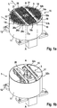
- a conveyor device 1 is shown.
- the conveyor device 1 has a linear conveyor unit described below and a rotating unit presented below for rotating the linear conveyor unit in the in the Figure 1a directions of rotation D shown.
- Part of the conveyor unit is a cylinder 11 fastened to a base 12 and a transport table 13. On its upper side, the cylinder 11 is closed off by a horizontal plane 14a forming a transport surface, which forms the outside of a first housing element 14.
- the attached cylinder 11 forms a second housing element 11.
- the first housing element 14 and the second housing element 11 are components of a housing 16 which encloses the rotary unit and at least partially the linear feed unit.
- a transport drive 3 of the linear conveyor unit is arranged on the transport table 13 in order to transport transport containers along the transport surface 14a of the transport table 13 in a transport direction L.
- the Figure 1b shows the conveyor 1 with removed first in the form of a plate-shaped housing element 14 and in the Figure 1c
- the conveyor device 1 is shown with the plate 14 removed and the cylinder 11 removed in order to outline the interior of the cylinder 11.
- the transport table 13 has a column 131 rotatably mounted on the base 12.
- the transport drive 3 is supported on the column 131. At the top of the column 131, this carries the plate 14. With the aid of a rotary drive 4, which is arranged in the interior of the cylinder 11, the transport table 13 can be rotated about the vertical axis A, in order to determine the transport direction L, namely the direction in who is transporting a transport container.
- the circular cylinder 11 fastened on the base 12 forms, together with the plate 14, a housing 16 which is at least closed at the top.
- the rotary drive 4 of the rotary unit and the transport drive 3 of the linear conveyor unit are arranged within this closed housing 16. I.e. all movably driven components of the rotary drive 4 or transport drive 3 are located within the closed housing 16 or are at a distance of less than 5 mm from this housing 16 and are therefore protected against unintentional contact.
- the rotary drive 4 comprises a rotary motor 41, which drives a toothed pulley via a belt transmission with a toothed belt 42, which is connected to the transport table 13 in a rotationally fixed manner.
- the rotary drive 4 can rotate the column 131 and thus the transport table 13 through 360 °, which is identified by the reference symbol D. Any angle of rotation can be set by using a position sensor or a servo motor and thus the transport direction L can be changed by any angle.
- the transport drive 3 is held on the transport table 13. That is, the transport drive 3 is moved when the transport table 13 is rotated.
- the transport drive 3 comprises a conveyor belt 31 with two conveyor belts 31 which are spaced apart from one another transversely to the transport direction L and are endlessly guided over deflection rollers 32a and 32b.
- the two conveyor belts 31 pass through two openings 17a, 17b made in the plate 14.
- the upper run 31o of a respective conveyor belt 31 therefore runs on top of the transport surface 14b of the transport table 13.
- the lower run 31u of the respective conveyor belt 31 and the drive motor 33 of the linear conveyor device are arranged below the transport surface 14, that is to say inside the closed housing 16.
- the drive motor 33 is connected via a gearbox to a third deflection roller 32c and drives one of the conveyor belts 31 via this.
- the two deflection rollers 32b are coupled to one another in a rotationally fixed manner, so that the drive motor 33 ultimately drives both conveyor belts 31 synchronously.
- the Figure 2 shows a transport container 91.
- the transport container 91 has a receiving space which can accommodate loose transport goods, in particular individual parts, for example optical lenses (for example spectacle lenses) or loose individual components (for example spectacle frames) or starting materials.
- An RFID tag is arranged on the transport container 91, on which data relating to the goods to be transported, that is to say for example the optical lens, are stored.
- the transport table 13 has an RFID transponder 26 in order to read or write data of the RFID tag. If the transported goods are blanks for the production of optical lenses, data on the lens to be produced can be stored via the RFID tag, which are used for setting or controlling processing machines.
- the transport container 91 also has a groove 911.
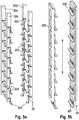
- the groove 911 can interact with a holding rail 251 in order to hold the transport container 91 or along one subsequently in connection with the Figures 5a and 5b guide rail 251 described in a straight direction.
- the transport table 13 has two guide plates 15 which are arranged on both sides of the conveyor belts 31.
- the distance between the two guide plates 15 is matched to the transverse extent of the transport containers 91 to be transported. That is, the distance between the two baffles 15 is dimensioned somewhat larger than the maximum transverse extent of a transport container 91 to be transported.
- a baffle plate 15 has a vertically extending leg which forms a left-hand or right-hand contact, on which a Transport container 91 can slide along. This prevents a transport container 91 from sliding off the conveyor belt 31 during transport to the left or right.
- the transport surface 14 is provided with recesses 14a.
- the recesses 14a are dimensioned such that, for example, a finger of a human hand cannot engage in these recesses.
- the recesses 14a are therefore less than or equal to 5 mm in their recess width 14c.
- the gap dimension 19a of the gap 19 between the fixed circular cylinder 11 and the moving outer edge of the plate 14 is less than or equal to 5 mm.
- the upper run 31o of the conveyor belt 31 is also guided above the transport surface 14b with a distance of less than or equal to 5 mm.
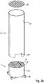
- FIGS. 3a to 3c show the conveyor device 1 upgraded with an optional module to a storage device 2.
- Figure 3a shows the conveyor device 1 with the bearing device 2 in a schematic representation and without a protective second cylinder 21.
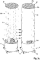
- Figure 3b shows an exploded view of the conveyor 1.
- Die Figure 3c shows the inner workings in the left representation and an external view of the conveying device 1 with storage device 2 in the right representation.
- the conveying device 1 has a first cylinder 11 and a second cylinder 21, which is connected to the first cylinder 11 and extends it upwards.
- the second cylinder 21 serves as a touch guard and prevents operating personnel from getting caught in moving parts of the bearing device 2.
- the second cylinder 21 has openings 211 on its underside through which a transport container 91 can be transported into the second cylinder 21 or out of the second cylinder 21.
- the transport containers 91 are transported by the transport drive 3 of the linear conveyor unit of the conveyor device 1.
- the top of the second cylinder 21 is covered by a grille 27.
- the cover grille 27 is designed as a round cover grille 27 and corresponds in its dimensions to the plate 14.
- the cover grille 27 has openings 27a which are dimensioned such that they are less than or equal to 5 mm in at least their opening width 27b are.
- the cover grid 27 covers such a surface that the conveyor device 2 has a surface coverage of less than 60%, preferably less than 50%, in a vertical projection. The conveyor device 2 can thus be flushed with a laminar stream of cleaned air without causing too much turbulence in the laminar flow.
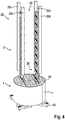
- the conveyor device 2 has a frame 22 with vertically running rails 22a, 22b, 22c and 22d. These vertical rails 22a, 22b, 22c and 22d are detachably connected to the underside of the plate 14 or to the transport table 13. The distance between the vertical rails 22a, 22b, 22c and 22d is matched to the dimensions of the transport containers 91. In the example shown, it is a stack 9 made up of a plurality of transport containers 91, 92, 93 and 94. The stack 9 is connected to the vertically running rails 22a, 22b, 22c and 22d by means of one in the Figures 4 to 5b shown holding device 25 held.
- a lifting drive 23 is provided.
- the lifting drive 23 can have a lifting motor which is arranged on the frame 22.
- the linear actuator is constructed in two parts. It has first fixed parts 231 which are held on the vertical rails 22a, 22b, 22c and 22d ( Figure 5a ). A second part 232 is mounted on it in a vertically displaceable manner ( Figure 5b ). Both parts 231 and 232 have horizontally running guide rails 251 which engage in the groove 911 of a transport container 91 in order to hold it.
- the holding rails 251 are mounted on the lifting drive 23, that is to say on the first part 231 or the second part 232, each pivotable about a pivot axis 252.
- the holding tickets 251 can be pivoted out of the groove 911 of a transport container 91 by means of a lifting magnet.
- the lifting of a transport container 91 takes place as follows: A transport container 91 is conveyed through the opening 211 and thereby slides with the groove 911 onto the holding rail 251 of the first and second part of the lifting drive 23. The holding rails of the fixed part 231 are then swung out so that the transport container 91 is only held by the holding rails of the movable part 232. This is then moved upwards and takes the transport container 91 with it. Arrived at the target position, the holding rails of the fixed part 231 are pivoted back into the groove 911 and hold the transport container 91 firmly. The holding rails of the movable part 232 can then be released and the movable part 232 can be moved down again. The lowering of a transport container 91 takes place in reverse order.
- lifting cylinders 24 can be provided, which are arranged in the housing 16 of the conveying device 1. As in Figure 6 shown, the lifting cylinders 24 are arranged below the transport surface 14b. A pneumatically or hydraulically driven lifting ram of a lifting cylinder 24 passes through the transport surface 14b through an opening 24a and extends upwards in order to raise a transport container 91. The gap dimension 24c of the gap 24b between the lifting cylinder 24 and the transport surface 14b is less than 5 mm in order to avoid crushing or shearing points.
- the conveyor device 1 stores transport containers 91 as FILO memories. This means that the transport container 91 stored first in the memory is the last to be output again.
- the storage device 2 can be rotated via the rotary drive 4 of the conveying device 1 in order to change the transport direction L of the transport containers 91 to be stored or output. It is essential here that the outer cylinder 21 of the bearing device 2 and the outer cylinder 11 of the rotary and linear conveying units of the conveying device 1 are stationary, that is, they do not move during the rotation D in order to reduce the risk of crushing or shearing.
- the opening 211 is matched to the dimensions of a transport container 91 such that there is a gap of less than or equal to 5 mm between a transport container 91 and the opening 211. In this way, fingers cannot be trapped during the input or output of transport containers 91.
- the driving force of the transport drive 3 can be limited to harmless values, so that the risk of injury is reduced.
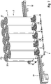
- the Figure 7 shows a storage arrangement with a matrix comprising several conveying devices 1 with storage device 2. It is a 5x2 matrix of conveying devices 2 which are each connected to 5 conveying devices 1 without a storage device.
- Transport containers 91, 92, 93, 94 are fed to the conveyor devices 1 and thus to the storage arrangement via a feed belt 51.
- a discharge belt 52 transports transport containers 91, 92, 93, 94 output from the storage arrangement.
- Transport containers 91, 92, 93, 94 are transported by pushing the feed belt 51, a transport container 91, onto the transport drive 3 of a conveyor device 1 until the conveyor belt 31 or the conveyor belts 31 of the transport drive 3 can grip the transport container 91 and transport it further .
- the removal is carried out by the conveyor belts 31 of the transport drive 3 of a conveying device 1 pushing the transport container 91 onto the discharge belt 52 to such an extent that it can take over the transport container 91 and transport it further.
- Two adjacent conveyor devices 2 are interconnected. Together, these form a FIFO memory arrangement.
- the transport containers 91, 92, 93, 94 are along the in Figure 7 transported by arrows indicated transport direction through the storage devices 2.
- a horizontal transport device 6 is arranged on the top of each of the storage devices 2. This transports the uppermost transport container 94 of a stack 9 horizontally and transfers it to the adjacent storage device 2.
- a transport container 91 therefore moves upwards in the first storage device 2 and is transferred horizontally to the second storage device 2. There the transport container 91 moves down again.
- a FIFO memory arrangement is implemented in this way.
- sensors are provided which monitor whether a transport container 91, 92, 93, 94 is located on an adjacent conveying device 1 or an adjacent transport surface 14b to then prevent rotation D.
- sensors are provided which monitor whether a transport container 91, 92, 93, 94 is located on an adjacent conveying device 1 or an adjacent transport surface 14b to then prevent rotation D.
- cameras or light barriers can be used as sensors.
- the conveying device 1 can either be used alone as a single device for transport purposes or optionally as a combination of several conveying devices 1.
- the conveying devices 1 can be arranged directly next to one another or one behind the other in order to implement complex distribution tasks.
- a larger bearing can also be provided by combining a large number of conveying devices 1 and combining them in the form of an N x M matrix, for example a 6 x 4 matrix, to form a larger bearing unit.
- N x M matrix for example a 6 x 4 matrix
- individual parts can be stored in the respective transport containers 91, 92, 93, 94 are included.
- a series connection of several storage devices 1 can also be provided, for example in order to increase the storage capacity or to increase the throughput time.
- a long throughput time is advantageous, for example, if the conveying device 1 is used as a cooling store for heated components.
- each conveyor device is organized as a so-called last-in-first-out storage device or two conveyor devices 1 are combined to form a first-in-first-out storage device. Due to the compact design, such a warehouse requires only a relatively small footprint.
Landscapes
- Engineering & Computer Science (AREA)
- Mechanical Engineering (AREA)
- Branching, Merging, And Special Transfer Between Conveyors (AREA)
- Specific Conveyance Elements (AREA)
Claims (4)
- Matrice NxM comprenant des dispositifs de convoyage (1), disposés directement les uns à côté des autres ou les uns derrière les autres, pour un récipient de transport (91, 92, 93, 94) pour des verres de lunette, chaque dispositif de convoyage (1) comportant :- une unité de convoyage linéaire (3, 31) destinée à convoyer le récipient de transport (91, 92) dans une direction rectiligne (L)- une unité rotative (4, 41, 42) destinée à effectuer une rotation (D) de l'unité de convoyage linéaire (3, 31)- un premier élément de boîtier (14) pour l'unité rotative (4, 41, 42), possédant un plan (14b) et accompagnant la rotation de l'unité de convoyage linéaire (3, 31) lors de sa rotation (D), le premier élément de boîtier (14) qui accompagne la rotation de l'unité de convoyage linéaire (3, 31) lors de sa rotation (D) possédant une ou plusieurs premières ouvertures (17a, 17b) à travers lesquelles l'unité de convoyage linéaire (3, 31) entrecoupe le plan (14b), l'unité de convoyage linéaire (3, 31) étant espacée du plan (14b) par un ou plusieurs interstices (18) ayant des cotes d'interstice (18a) associées,- les cotes d'interstice (18a) de tous les interstices (18) étant égales ou inférieures à 5 mm,- le premier élément de boîtier (14) ne possédant aucune deuxième ouverture supplémentaire ou une pluralité de deuxièmes ouvertures (14a) pénétrant au niveau du plan (14b) et ayant des largeurs d'ouverture (14c) associées, les largeurs d'ouverture (14c) de toutes les deuxièmes ouvertures (14a) étant inférieures ou égales à 5 mm,- un deuxième élément de boîtier (11) de forme cylindrique creuse fixe qui entoure l'unité rotative (4, 41, 42) étant présent, lequel n'accompagne pas la rotation de l'unité de convoyage linéaire (3, 31) lors de sa rotation (D),- le plan (14b) du premier élément de boîtier (14) qui accompagne la rotation de l'unité de convoyage linéaire (3, 31) lors de sa rotation (D) se trouvant à l'intérieur du deuxième élément de boîtier (11) fixe et étant de forme complémentaire au deuxième élément de boîtier (11) fixe,- l'unité rotative (4, 41, 42) et tous les composants entraînés du dispositif de convoyage (1) étant disposés entièrement à l'intérieur du deuxième élément de boîtier (11) de forme cylindrique creuse et- le deuxième élément de boîtier (11) de forme cylindrique creuse étant réalisé sous la forme d'une enveloppe fermée en elle-même, qui ne possède aucune ou une pluralité d'ouvertures rondes ou rectangulaires dont les diamètres on dont la largeur libre ou la longueur libre sont inférieurs ou égaux à 5 mm.
- Utilisation d'un dispositif de convoyage (1) pour un récipient de transport (91, 92, 93, 94) pour des verres de lunette dans une matrice NxM constituée d'une pluralité de ces dispositifs de convoyage (1), qui sont disposés directement les uns à côté des autres ou les uns derrière les autres, le dispositif de convoyage (1) comportant :- une unité de convoyage linéaire (3, 31) destinée à convoyer le récipient de transport (91, 92) dans une direction rectiligne (L)- une unité rotative (4, 41, 42) destinée à effectuer une rotation (D) de l'unité de convoyage linéaire (3, 31)- un premier élément de boîtier (14) pour l'unité rotative (4, 41, 42), possédant un plan (14b) et accompagnant la rotation de l'unité de convoyage linéaire (3, 31) lors de sa rotation (D), le premier élément de boîtier (14) qui accompagne la rotation de l'unité de convoyage linéaire (3, 31) lors de sa rotation (D) possédant une ou plusieurs premières ouvertures (17a, 17b) à travers lesquelles l'unité de convoyage linéaire (3, 31) entrecoupe le plan (14b), l'unité de convoyage linéaire (3, 31) étant espacée du plan (14b) par un ou plusieurs interstices (18) ayant des cotes d'interstice (18a) associées,- les cotes d'interstice (18a) de tous les interstices (18) étant égales ou inférieures à 5 mm,- le premier élément de boîtier (14) ne possédant aucune deuxième ouverture supplémentaire ou une pluralité de deuxièmes ouvertures (14a) pénétrant au niveau du plan (14b) et ayant des largeurs d'ouverture (14c) associées, les largeurs d'ouverture (14c) de toutes les deuxièmes ouvertures (14a) étant inférieures ou égales à 5 mm,- un deuxième élément de boîtier (11) de forme cylindrique creuse fixe qui entoure l'unité rotative (4, 41, 42) étant présent, lequel n'accompagne pas la rotation de l'unité de convoyage linéaire (3, 31) lors de sa rotation (D),- le plan (14b) du premier élément de boîtier (14) qui accompagne la rotation de l'unité de convoyage linéaire (3, 31) lors de sa rotation (D) se trouvant à l'intérieur du deuxième élément de boîtier (11) fixe et étant de forme complémentaire au deuxième élément de boîtier (11) fixe,- l'unité rotative (4, 41, 42) et tous les composants entraînés du dispositif de convoyage (1) étant disposés entièrement à l'intérieur du deuxième élément de boîtier (11) de forme cylindrique creuse et- le deuxième élément de boîtier (11) de forme cylindrique creuse étant réalisé sous la forme d'une enveloppe fermée en elle-même, qui ne possède aucune ou une pluralité d'ouvertures rondes ou rectangulaires dont les diamètres on dont la largeur libre ou la longueur libre sont inférieurs ou égaux à 5 mm.
- Dispositif de convoyage (1) pour un récipient de transport (91, 92, 93, 94) pour des verres de lunette, comprenant :- une unité de convoyage linéaire (3, 31) destinée à convoyer le récipient de transport (91, 92) dans une direction rectiligne (L)- une unité rotative (4, 41, 42) destinée à effectuer une rotation (D) de l'unité de convoyage linéaire (3, 31)- un premier élément de boîtier (14) pour l'unité rotative (4, 41, 42), possédant un plan (14b) et accompagnant la rotation de l'unité de convoyage linéaire (3, 31) lors de sa rotation (D), le premier élément de boîtier (14) qui accompagne la rotation de l'unité de convoyage linéaire (3, 31) lors de sa rotation (D) possédant une ou plusieurs premières ouvertures (17a, 17b) à travers lesquelles l'unité de convoyage linéaire (3, 31) entrecoupe le plan (14b), l'unité de convoyage linéaire (3, 31) étant espacée du plan (14b) par un ou plusieurs interstices (18) ayant des cotes d'interstice (18a) associées,- les cotes d'interstice (18a) de tous les interstices (18) étant égales ou inférieures à 5 mm et le premier élément de boîtier (14) ne possédant aucune deuxième ouverture supplémentaire ou une pluralité de deuxièmes ouvertures (14a) pénétrant au niveau du plan (14b) et ayant des largeurs d'ouverture (14c) associées, les largeurs d'ouverture (14c) de toutes les deuxièmes ouvertures (14a) étant inférieures ou égales à 5 mm,- un deuxième élément de boîtier (11) de forme cylindrique creuse fixe qui entoure l'unité rotative (4, 41, 42) étant présent, lequel n'accompagne pas la rotation de l'unité de convoyage linéaire (3, 31) lors de sa rotation (D),- le plan (14b) du premier élément de boîtier (14) qui accompagne la rotation de l'unité de convoyage linéaire (3, 31) lors de sa rotation (D) se trouvant à l'intérieur du deuxième élément de boîtier (11) fixe et étant de forme complémentaire au deuxième élément de boîtier (11) fixe,- l'unité rotative (4, 41, 42) et tous les composants entraînés du dispositif de convoyage (1) étant disposés entièrement à l'intérieur du deuxième élément de boîtier (11) de forme cylindrique creuse et- le deuxième élément de boîtier (11) de forme cylindrique creuse étant réalisé sous la forme d'une enveloppe fermée en elle-même, qui ne possède aucune ou une pluralité d'ouvertures rondes ou rectangulaires dont les diamètres on dont la largeur libre ou la longueur libre sont inférieurs ou égaux à 5 mm,un dispositif de maintien (25) étant présent pour maintenir les récipients de transport (91, 92, 93, 94) à une distance donnée au-dessus du plan (14b),- un dispositif de levage (23) étant présent pour lever les récipients de transport (91, 92) du plan (14b) dans la direction verticale et/ou les abaisser sur du plan (14b) et- le dispositif de levage (23) est conçu pour lever les récipients de transport (91, 92) à une distance au-dessus du plan (14b) de sorte que le dispositif de maintien (25) étant présent peut maintenir les récipients de transport (91, 92, 93, 94), le dispositif de levage (23) possédant un ou plusieurs vérins de levage (24) pour lever ou abaisser les récipients de transport (91, 92, 93, 94) dans la direction verticale, le premier élément de boîtier (14) qui accompagne la rotation de l'unité de convoyage linéaire (3, 31) lors de sa rotation (D) possédant une ou plusieurs quatrièmes ouvertures (24a) à travers lesquelles l'un ou les plusieurs vérins de levage (24) entrecoupe ou entrecoupent le plan.
- Dispositif de convoyage (1) selon la revendication 3, caractérisé en ce l'un ou les plusieurs vérins de levage (24) et ou sont espacé(s) du plan (14b) par un ou plusieurs interstices (24b) ayant des cotes d'interstice (24c) associées et en ce que les cotes d'interstice (24c) de tous les interstices (24b) sont inférieures ou égales à 5 mm.
Applications Claiming Priority (2)
| Application Number | Priority Date | Filing Date | Title |
|---|---|---|---|
| DE102016225485.5A DE102016225485B4 (de) | 2016-12-19 | 2016-12-19 | Sicheres Fördersystem |
| PCT/EP2017/078871 WO2018114135A1 (fr) | 2016-12-19 | 2017-11-10 | Système de transport sûr |
Publications (2)
| Publication Number | Publication Date |
|---|---|
| EP3554975A1 EP3554975A1 (fr) | 2019-10-23 |
| EP3554975B1 true EP3554975B1 (fr) | 2020-05-27 |
Family
ID=60331601
Family Applications (1)
| Application Number | Title | Priority Date | Filing Date |
|---|---|---|---|
| EP17798183.4A Active EP3554975B1 (fr) | 2016-12-19 | 2017-11-10 | Système de transport sûr |
Country Status (5)
| Country | Link |
|---|---|
| US (1) | US10569961B2 (fr) |
| EP (1) | EP3554975B1 (fr) |
| DE (1) | DE102016225485B4 (fr) |
| ES (1) | ES2802778T3 (fr) |
| WO (1) | WO2018114135A1 (fr) |
Families Citing this family (3)
| Publication number | Priority date | Publication date | Assignee | Title |
|---|---|---|---|---|
| HUE051238T2 (hu) * | 2016-12-19 | 2021-03-01 | Zeiss Carl Vision Int Gmbh | Továbbító berendezés egy szállítótartály számára |
| US12163940B2 (en) * | 2019-10-17 | 2024-12-10 | Design West Technologies, Inc. | CBRNE sensors and system for monitoring and deploying same |
| CN113859960B (zh) * | 2021-09-30 | 2022-05-27 | 深圳市爱租机科技有限公司 | 一种线上共享租赁用线下租赁物品分类装置 |
Family Cites Families (17)
| Publication number | Priority date | Publication date | Assignee | Title |
|---|---|---|---|---|
| DE7219720U (de) * | 1972-11-16 | Wickersheim Verpackungsmaschinen Gmbh & Co | Förder- und Ausrichtvorrichtung für unverpackte, zu Stapeln zusammengefaßte Zeitschriften oder Zeitungen als Zuteilungsstation für Verpackungsautomaten | |
| GB1389820A (en) * | 1971-05-05 | 1975-04-09 | Torvale Holdings Ltd | Material handling equipment |
| GB1596015A (en) | 1976-12-09 | 1981-08-19 | Baptie P J | Load carrying vehicles |
| JPS6337023A (ja) * | 1986-07-31 | 1988-02-17 | Matsushita Electric Ind Co Ltd | 昇降装置 |
| JPH01156225A (ja) * | 1987-12-15 | 1989-06-19 | Daiichi Kogyo Kk | 曲り搬送装置 |
| CA1313001C (fr) * | 1989-08-30 | 1993-01-26 | Stanley A. Desalvo | Rampe portable |
| US5078257A (en) * | 1989-11-21 | 1992-01-07 | Donald W. Carter, Jr. | Lattice production line and method of operating such a line |
| DE4119790C2 (de) * | 1991-06-15 | 1996-08-14 | Protech Automation Gmbh | Umsetzstation für eine Fördervorrichtung |
| DE4335195A1 (de) * | 1993-10-15 | 1995-04-20 | Altratec Montagesysteme | Transportstrecke |
| DE29506230U1 (de) * | 1995-04-11 | 1995-06-22 | Segbert GmbH & Co. KG, 48619 Heek | Vorrichtung zum Verteilen von Paketen lose gestapelter Druckerzeugnisse |
| US6308818B1 (en) * | 1999-08-02 | 2001-10-30 | Asyst Technologies, Inc. | Transport system with integrated transport carrier and directors |
| AT413505B (de) * | 2001-03-09 | 2006-03-15 | Sticht Fertigungstech Stiwa | Fertigungsanlage für die montage und/oder bearbeitung von auf werkstückträgern transportierten bauteilen |
| US20070137981A1 (en) * | 2005-12-16 | 2007-06-21 | Russell Kettelson | Configurable modular chain-driven pallet transfer system |
| JP2008174318A (ja) | 2007-01-16 | 2008-07-31 | Ito Denki Kk | 搬送モジュール、並びに、搬送装置 |
| ITUD20070197A1 (it) * | 2007-10-24 | 2009-04-25 | Baccini S P A | Dispositivo e procedimento di allineamento per allineare piastre per circuiti elettronici |
| US9014844B2 (en) | 2011-12-22 | 2015-04-21 | Amazon Technologies, Inc. | Methods and apparatus for stacking receptacles in materials handling facilities |
| SG11201603110PA (en) * | 2013-10-28 | 2016-05-30 | Murata Machinery Ltd | Conveyor device |
-
2016
- 2016-12-19 DE DE102016225485.5A patent/DE102016225485B4/de active Active
-
2017
- 2017-11-10 WO PCT/EP2017/078871 patent/WO2018114135A1/fr not_active Ceased
- 2017-11-10 ES ES17798183T patent/ES2802778T3/es active Active
- 2017-11-10 EP EP17798183.4A patent/EP3554975B1/fr active Active
-
2019
- 2019-06-18 US US16/444,373 patent/US10569961B2/en active Active
Non-Patent Citations (1)
| Title |
|---|
| None * |
Also Published As
| Publication number | Publication date |
|---|---|
| WO2018114135A1 (fr) | 2018-06-28 |
| ES2802778T3 (es) | 2021-01-21 |
| US20190300290A1 (en) | 2019-10-03 |
| DE102016225485B4 (de) | 2022-08-25 |
| US10569961B2 (en) | 2020-02-25 |
| DE102016225485A1 (de) | 2018-06-21 |
| EP3554975A1 (fr) | 2019-10-23 |
Similar Documents
| Publication | Publication Date | Title |
|---|---|---|
| EP2794433B1 (fr) | Installation de préparation des commandes et procédé de préparation des marchandises commandées | |
| EP3279118B1 (fr) | Système de transport | |
| EP3248914B1 (fr) | Glissière pour marchandise de détail et procédé d'utilisation d'une telle glissière | |
| EP2821353B1 (fr) | Section de transport d'un dispositif de convoyage horizontal ayant au moins un élément de guidage réglable | |
| EP3652096B1 (fr) | Dispositif de stockage et de convoyeur et procédé de fonctionnement du dispositif de stockage et de convoyeur | |
| EP2608917B1 (fr) | Dispositif de sciage | |
| EP3554975B1 (fr) | Système de transport sûr | |
| EP1360656B1 (fr) | Unite destinee a des systemes automatiques de reprise de contenants | |
| DE69218608T2 (de) | Speicherabdeckung | |
| DE3637003C1 (de) | Transportdeck fuer Stueckgueter oder dergleichen | |
| EP2784006B1 (fr) | Système de préparation de commandes | |
| CH663404A5 (en) | Method for the conveying of mass parts and apparatus for carrying out the method | |
| DE102016225483B4 (de) | Fördervorrichtung | |
| DE1806888A1 (de) | Foerdervorrichtung zum Ausrichten von Gegenstaenden | |
| DE3627038A1 (de) | Einrichtung zum zerkleinern von grossformatigen kuehlgutbloecken u.dgl., insbesondere fuer die tierfutterherstellung | |
| DE3107438A1 (de) | "einrichtung zum zentrierenden ausrichten von plattenfoermigen werkstuecken" | |
| DE3336988C2 (de) | Vorrichtung zum Zufördern von in großer Anzahl anfallenden Gegenständen | |
| DE10134602B4 (de) | Bandförderer für Stückgut | |
| EP0483446A1 (fr) | Dispositif de protection pour machine d'emballage | |
| EP2984009B1 (fr) | Dispositif de conservation limitée dans le temps d'objets | |
| DE20319973U1 (de) | Vorrichtung zur Drehung von Behältern | |
| DE29700863U1 (de) | Fördervorrichtung, insbesondere zum Ausschleusen und/oder Vereinzeln von Gütern | |
| DE4007481C2 (fr) | ||
| EP2318297B1 (fr) | Procédé et dispositif pour retourner un récipient | |
| EP2679504A1 (fr) | Machine de fermeture de coques avec dispositif de déplacement en avant |
Legal Events
| Date | Code | Title | Description |
|---|---|---|---|
| STAA | Information on the status of an ep patent application or granted ep patent |
Free format text: STATUS: UNKNOWN |
|
| STAA | Information on the status of an ep patent application or granted ep patent |
Free format text: STATUS: THE INTERNATIONAL PUBLICATION HAS BEEN MADE |
|
| PUAI | Public reference made under article 153(3) epc to a published international application that has entered the european phase |
Free format text: ORIGINAL CODE: 0009012 |
|
| STAA | Information on the status of an ep patent application or granted ep patent |
Free format text: STATUS: REQUEST FOR EXAMINATION WAS MADE |
|
| 17P | Request for examination filed |
Effective date: 20190719 |
|
| AK | Designated contracting states |
Kind code of ref document: A1 Designated state(s): AL AT BE BG CH CY CZ DE DK EE ES FI FR GB GR HR HU IE IS IT LI LT LU LV MC MK MT NL NO PL PT RO RS SE SI SK SM TR |
|
| AX | Request for extension of the european patent |
Extension state: BA ME |
|
| GRAP | Despatch of communication of intention to grant a patent |
Free format text: ORIGINAL CODE: EPIDOSNIGR1 |
|
| STAA | Information on the status of an ep patent application or granted ep patent |
Free format text: STATUS: GRANT OF PATENT IS INTENDED |
|
| DAV | Request for validation of the european patent (deleted) | ||
| DAX | Request for extension of the european patent (deleted) | ||
| INTG | Intention to grant announced |
Effective date: 20200114 |
|
| GRAS | Grant fee paid |
Free format text: ORIGINAL CODE: EPIDOSNIGR3 |
|
| GRAA | (expected) grant |
Free format text: ORIGINAL CODE: 0009210 |
|
| STAA | Information on the status of an ep patent application or granted ep patent |
Free format text: STATUS: THE PATENT HAS BEEN GRANTED |
|
| AK | Designated contracting states |
Kind code of ref document: B1 Designated state(s): AL AT BE BG CH CY CZ DE DK EE ES FI FR GB GR HR HU IE IS IT LI LT LU LV MC MK MT NL NO PL PT RO RS SE SI SK SM TR |
|
| REG | Reference to a national code |
Ref country code: GB Ref legal event code: FG4D Free format text: NOT ENGLISH |
|
| REG | Reference to a national code |
Ref country code: CH Ref legal event code: EP |
|
| REG | Reference to a national code |
Ref country code: DE Ref legal event code: R096 Ref document number: 502017005494 Country of ref document: DE |
|
| REG | Reference to a national code |
Ref country code: AT Ref legal event code: REF Ref document number: 1274344 Country of ref document: AT Kind code of ref document: T Effective date: 20200615 |
|
| REG | Reference to a national code |
Ref country code: LT Ref legal event code: MG4D |
|
| PG25 | Lapsed in a contracting state [announced via postgrant information from national office to epo] |
Ref country code: LT Free format text: LAPSE BECAUSE OF FAILURE TO SUBMIT A TRANSLATION OF THE DESCRIPTION OR TO PAY THE FEE WITHIN THE PRESCRIBED TIME-LIMIT Effective date: 20200527 Ref country code: NO Free format text: LAPSE BECAUSE OF FAILURE TO SUBMIT A TRANSLATION OF THE DESCRIPTION OR TO PAY THE FEE WITHIN THE PRESCRIBED TIME-LIMIT Effective date: 20200827 Ref country code: FI Free format text: LAPSE BECAUSE OF FAILURE TO SUBMIT A TRANSLATION OF THE DESCRIPTION OR TO PAY THE FEE WITHIN THE PRESCRIBED TIME-LIMIT Effective date: 20200527 Ref country code: GR Free format text: LAPSE BECAUSE OF FAILURE TO SUBMIT A TRANSLATION OF THE DESCRIPTION OR TO PAY THE FEE WITHIN THE PRESCRIBED TIME-LIMIT Effective date: 20200828 Ref country code: SE Free format text: LAPSE BECAUSE OF FAILURE TO SUBMIT A TRANSLATION OF THE DESCRIPTION OR TO PAY THE FEE WITHIN THE PRESCRIBED TIME-LIMIT Effective date: 20200527 Ref country code: IS Free format text: LAPSE BECAUSE OF FAILURE TO SUBMIT A TRANSLATION OF THE DESCRIPTION OR TO PAY THE FEE WITHIN THE PRESCRIBED TIME-LIMIT Effective date: 20200927 Ref country code: PT Free format text: LAPSE BECAUSE OF FAILURE TO SUBMIT A TRANSLATION OF THE DESCRIPTION OR TO PAY THE FEE WITHIN THE PRESCRIBED TIME-LIMIT Effective date: 20200928 |
|
| REG | Reference to a national code |
Ref country code: NL Ref legal event code: MP Effective date: 20200527 |
|
| PG25 | Lapsed in a contracting state [announced via postgrant information from national office to epo] |
Ref country code: LV Free format text: LAPSE BECAUSE OF FAILURE TO SUBMIT A TRANSLATION OF THE DESCRIPTION OR TO PAY THE FEE WITHIN THE PRESCRIBED TIME-LIMIT Effective date: 20200527 Ref country code: RS Free format text: LAPSE BECAUSE OF FAILURE TO SUBMIT A TRANSLATION OF THE DESCRIPTION OR TO PAY THE FEE WITHIN THE PRESCRIBED TIME-LIMIT Effective date: 20200527 Ref country code: HR Free format text: LAPSE BECAUSE OF FAILURE TO SUBMIT A TRANSLATION OF THE DESCRIPTION OR TO PAY THE FEE WITHIN THE PRESCRIBED TIME-LIMIT Effective date: 20200527 Ref country code: BG Free format text: LAPSE BECAUSE OF FAILURE TO SUBMIT A TRANSLATION OF THE DESCRIPTION OR TO PAY THE FEE WITHIN THE PRESCRIBED TIME-LIMIT Effective date: 20200827 |
|
| PG25 | Lapsed in a contracting state [announced via postgrant information from national office to epo] |
Ref country code: NL Free format text: LAPSE BECAUSE OF FAILURE TO SUBMIT A TRANSLATION OF THE DESCRIPTION OR TO PAY THE FEE WITHIN THE PRESCRIBED TIME-LIMIT Effective date: 20200527 Ref country code: AL Free format text: LAPSE BECAUSE OF FAILURE TO SUBMIT A TRANSLATION OF THE DESCRIPTION OR TO PAY THE FEE WITHIN THE PRESCRIBED TIME-LIMIT Effective date: 20200527 |
|
| REG | Reference to a national code |
Ref country code: ES Ref legal event code: FG2A Ref document number: 2802778 Country of ref document: ES Kind code of ref document: T3 Effective date: 20210121 |
|
| PG25 | Lapsed in a contracting state [announced via postgrant information from national office to epo] |
Ref country code: DK Free format text: LAPSE BECAUSE OF FAILURE TO SUBMIT A TRANSLATION OF THE DESCRIPTION OR TO PAY THE FEE WITHIN THE PRESCRIBED TIME-LIMIT Effective date: 20200527 Ref country code: EE Free format text: LAPSE BECAUSE OF FAILURE TO SUBMIT A TRANSLATION OF THE DESCRIPTION OR TO PAY THE FEE WITHIN THE PRESCRIBED TIME-LIMIT Effective date: 20200527 Ref country code: SM Free format text: LAPSE BECAUSE OF FAILURE TO SUBMIT A TRANSLATION OF THE DESCRIPTION OR TO PAY THE FEE WITHIN THE PRESCRIBED TIME-LIMIT Effective date: 20200527 Ref country code: RO Free format text: LAPSE BECAUSE OF FAILURE TO SUBMIT A TRANSLATION OF THE DESCRIPTION OR TO PAY THE FEE WITHIN THE PRESCRIBED TIME-LIMIT Effective date: 20200527 Ref country code: CZ Free format text: LAPSE BECAUSE OF FAILURE TO SUBMIT A TRANSLATION OF THE DESCRIPTION OR TO PAY THE FEE WITHIN THE PRESCRIBED TIME-LIMIT Effective date: 20200527 |
|
| PG25 | Lapsed in a contracting state [announced via postgrant information from national office to epo] |
Ref country code: SK Free format text: LAPSE BECAUSE OF FAILURE TO SUBMIT A TRANSLATION OF THE DESCRIPTION OR TO PAY THE FEE WITHIN THE PRESCRIBED TIME-LIMIT Effective date: 20200527 Ref country code: PL Free format text: LAPSE BECAUSE OF FAILURE TO SUBMIT A TRANSLATION OF THE DESCRIPTION OR TO PAY THE FEE WITHIN THE PRESCRIBED TIME-LIMIT Effective date: 20200527 |
|
| REG | Reference to a national code |
Ref country code: DE Ref legal event code: R097 Ref document number: 502017005494 Country of ref document: DE |
|
| PLBE | No opposition filed within time limit |
Free format text: ORIGINAL CODE: 0009261 |
|
| STAA | Information on the status of an ep patent application or granted ep patent |
Free format text: STATUS: NO OPPOSITION FILED WITHIN TIME LIMIT |
|
| 26N | No opposition filed |
Effective date: 20210302 |
|
| PG25 | Lapsed in a contracting state [announced via postgrant information from national office to epo] |
Ref country code: MC Free format text: LAPSE BECAUSE OF FAILURE TO SUBMIT A TRANSLATION OF THE DESCRIPTION OR TO PAY THE FEE WITHIN THE PRESCRIBED TIME-LIMIT Effective date: 20200527 |
|
| REG | Reference to a national code |
Ref country code: CH Ref legal event code: PL |
|
| PG25 | Lapsed in a contracting state [announced via postgrant information from national office to epo] |
Ref country code: LU Free format text: LAPSE BECAUSE OF NON-PAYMENT OF DUE FEES Effective date: 20201110 |
|
| PG25 | Lapsed in a contracting state [announced via postgrant information from national office to epo] |
Ref country code: LI Free format text: LAPSE BECAUSE OF NON-PAYMENT OF DUE FEES Effective date: 20201130 Ref country code: CH Free format text: LAPSE BECAUSE OF NON-PAYMENT OF DUE FEES Effective date: 20201130 |
|
| PG25 | Lapsed in a contracting state [announced via postgrant information from national office to epo] |
Ref country code: IE Free format text: LAPSE BECAUSE OF NON-PAYMENT OF DUE FEES Effective date: 20201110 |
|
| PG25 | Lapsed in a contracting state [announced via postgrant information from national office to epo] |
Ref country code: TR Free format text: LAPSE BECAUSE OF FAILURE TO SUBMIT A TRANSLATION OF THE DESCRIPTION OR TO PAY THE FEE WITHIN THE PRESCRIBED TIME-LIMIT Effective date: 20200527 Ref country code: MT Free format text: LAPSE BECAUSE OF FAILURE TO SUBMIT A TRANSLATION OF THE DESCRIPTION OR TO PAY THE FEE WITHIN THE PRESCRIBED TIME-LIMIT Effective date: 20200527 Ref country code: CY Free format text: LAPSE BECAUSE OF FAILURE TO SUBMIT A TRANSLATION OF THE DESCRIPTION OR TO PAY THE FEE WITHIN THE PRESCRIBED TIME-LIMIT Effective date: 20200527 |
|
| PG25 | Lapsed in a contracting state [announced via postgrant information from national office to epo] |
Ref country code: MK Free format text: LAPSE BECAUSE OF FAILURE TO SUBMIT A TRANSLATION OF THE DESCRIPTION OR TO PAY THE FEE WITHIN THE PRESCRIBED TIME-LIMIT Effective date: 20200527 |
|
| GBPC | Gb: european patent ceased through non-payment of renewal fee |
Effective date: 20211110 |
|
| PG25 | Lapsed in a contracting state [announced via postgrant information from national office to epo] |
Ref country code: GB Free format text: LAPSE BECAUSE OF NON-PAYMENT OF DUE FEES Effective date: 20211110 |
|
| PG25 | Lapsed in a contracting state [announced via postgrant information from national office to epo] |
Ref country code: SI Free format text: LAPSE BECAUSE OF FAILURE TO SUBMIT A TRANSLATION OF THE DESCRIPTION OR TO PAY THE FEE WITHIN THE PRESCRIBED TIME-LIMIT Effective date: 20200527 |
|
| REG | Reference to a national code |
Ref country code: AT Ref legal event code: MM01 Ref document number: 1274344 Country of ref document: AT Kind code of ref document: T Effective date: 20221110 |
|
| PG25 | Lapsed in a contracting state [announced via postgrant information from national office to epo] |
Ref country code: AT Free format text: LAPSE BECAUSE OF NON-PAYMENT OF DUE FEES Effective date: 20221110 |
|
| PGFP | Annual fee paid to national office [announced via postgrant information from national office to epo] |
Ref country code: DE Payment date: 20251119 Year of fee payment: 9 |
|
| PGFP | Annual fee paid to national office [announced via postgrant information from national office to epo] |
Ref country code: IT Payment date: 20251125 Year of fee payment: 9 |
|
| PGFP | Annual fee paid to national office [announced via postgrant information from national office to epo] |
Ref country code: FR Payment date: 20251126 Year of fee payment: 9 |
|
| PGFP | Annual fee paid to national office [announced via postgrant information from national office to epo] |
Ref country code: BE Payment date: 20251119 Year of fee payment: 9 |
|
| PGFP | Annual fee paid to national office [announced via postgrant information from national office to epo] |
Ref country code: ES Payment date: 20251229 Year of fee payment: 9 |