EP3555411B1 - Foret - Google Patents
Foret Download PDFInfo
- Publication number
- EP3555411B1 EP3555411B1 EP17821501.8A EP17821501A EP3555411B1 EP 3555411 B1 EP3555411 B1 EP 3555411B1 EP 17821501 A EP17821501 A EP 17821501A EP 3555411 B1 EP3555411 B1 EP 3555411B1
- Authority
- EP
- European Patent Office
- Prior art keywords
- chisel edge
- drilling head
- primary
- arms
- rotation
- Prior art date
- Legal status (The legal status is an assumption and is not a legal conclusion. Google has not performed a legal analysis and makes no representation as to the accuracy of the status listed.)
- Active
Links
Images


Classifications
-
- B—PERFORMING OPERATIONS; TRANSPORTING
- B23—MACHINE TOOLS; METAL-WORKING NOT OTHERWISE PROVIDED FOR
- B23B—TURNING; BORING
- B23B51/00—Tools for drilling machines
-
- B—PERFORMING OPERATIONS; TRANSPORTING
- B28—WORKING CEMENT, CLAY, OR STONE
- B28D—WORKING STONE OR STONE-LIKE MATERIALS
- B28D1/00—Working stone or stone-like materials, e.g. brick, concrete or glass, not provided for elsewhere; Machines, devices, tools therefor
- B28D1/14—Working stone or stone-like materials, e.g. brick, concrete or glass, not provided for elsewhere; Machines, devices, tools therefor by boring or drilling
- B28D1/146—Tools therefor
-
- E—FIXED CONSTRUCTIONS
- E21—EARTH OR ROCK DRILLING; MINING
- E21B—EARTH OR ROCK DRILLING; OBTAINING OIL, GAS, WATER, SOLUBLE OR MELTABLE MATERIALS OR A SLURRY OF MINERALS FROM WELLS
- E21B10/00—Drill bits
- E21B10/44—Bits with helical conveying portion, e.g. screw type bits; Augers with leading portion or with detachable parts
- E21B10/445—Bits with helical conveying portion, e.g. screw type bits; Augers with leading portion or with detachable parts percussion type, e.g. for masonry
-
- B—PERFORMING OPERATIONS; TRANSPORTING
- B23—MACHINE TOOLS; METAL-WORKING NOT OTHERWISE PROVIDED FOR
- B23B—TURNING; BORING
- B23B2226/00—Materials of tools or workpieces not comprising a metal
- B23B2226/75—Stone, rock or concrete
-
- B—PERFORMING OPERATIONS; TRANSPORTING
- B23—MACHINE TOOLS; METAL-WORKING NOT OTHERWISE PROVIDED FOR
- B23B—TURNING; BORING
- B23B2251/00—Details of tools for drilling machines
- B23B2251/14—Configuration of the cutting part, i.e. the main cutting edges
-
- B—PERFORMING OPERATIONS; TRANSPORTING
- B23—MACHINE TOOLS; METAL-WORKING NOT OTHERWISE PROVIDED FOR
- B23B—TURNING; BORING
- B23B2251/00—Details of tools for drilling machines
- B23B2251/18—Configuration of the drill point
-
- B—PERFORMING OPERATIONS; TRANSPORTING
- B23—MACHINE TOOLS; METAL-WORKING NOT OTHERWISE PROVIDED FOR
- B23B—TURNING; BORING
- B23B2251/00—Details of tools for drilling machines
- B23B2251/20—Number of cutting edges
- B23B2251/208—Eight cutting edges
Definitions
- the present invention relates to a drill head for a drill for the percussive mining of mineral building materials, as EP 1 944 108 A2 known and described in the preamble of claim 1.
- the present invention also relates to a drill.
- a drill for the percussive mining of mineral building materials is, for example, made of EP1604793 A1 known.
- the drill head for a drill contains the features of claim 1 and has an upper side for mining mineral material, a lower side for fastening to a shaft of the drill, and an axis of rotation which runs centrally through the upper side and the lower side.
- the drill head has arms, each having an end proximal to the axis of rotation and an end distal to the axis of rotation, and wherein the upper sides of the arms each have primary chisel edges running in the direction from the proximal end to the distal end. At least one, preferably at least two, of the arms have a secondary chisel edge on the upper side running along the primary chisel edge. The secondary chisel edge promotes the mining of steel reinforcements in the rock.
- the primary chisel edge and the secondary chisel edge of the same arm start at the distal end of the arm.
- the mining of the reinforcements in contrast to the mining of the mineral material, is dominated by the outer areas of the drill head.
- the primary chisel edge protrudes continuously in the direction of impact compared to the secondary chisel edge of the same arm, ie it is higher.
- the secondary chisel edge comes into contact with the material somewhat later than the primary chisel edge.
- the primary chisel edge begins to shear off part of the reinforcement, which the secondary chisel edge can then bend.
- the secondary chisel edge is offset in a direction of rotation of the drill head in relation to the primary chisel edge of the same arm.
- One embodiment provides that the angle between the primary chisel edge and the secondary chisel edge of the same arm is less than 8 degrees. The two chisel edges are sufficiently close for the secondary chisel edge to be able to pick up the metal chip.
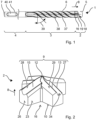
- Fig. 1 shows an example drill 1.
- the drill 1 has a drill head 2, a spiral 3 and an insertion end 4.
- the drill 1 is designed for the extraction of mineral materials, in particular for the extraction of reinforced concrete.
- the drill 1 is rotated in a direction of rotation 5 around its longitudinal axis 6 (axis of rotation).
- the typical direction of rotation 5 is counterclockwise when looking at the drill head 2.
- the direction of rotation 5 is counterclockwise.
- the drill 1 can be used in a hand-held power tool which has a corresponding rotary drive.
- a percussion mechanism of the hand-held power tool periodically strikes an impact surface 7 on the exposed front surface of the insertion end 4.
- the shock wave of the impacts runs through the spiral 3 in the impact direction 8 to the drill head 2.
- the drill head 2 shatters the material.
- the rotary movement firstly ensures that the drill head 2 is under different Orientations on the subsoil and the borehole is evenly knocked out, and in the illustrated drill 1 with spiral 3, causes the drilling material to be transported out of the borehole by means of the (transport) spiral 3.
- the drill 1 can have a hollow cylindrical shaft. The drilling material is sucked out of the drill head 2 through the hollow shaft 3 by means of a blower.
- the body of the drill head 2 has a straight-prismatic basic shape with a star-shaped base surface, for example.
- the basic shape is obtained by moving the base surface parallel to the axis of rotation 6.
- the base surface corresponds to the top view of the drill head 2, ie the silhouette of a top side 9.
- the axis of rotation 6 runs centrally through the base surface, ergo centrally through a bottom side 10 and the top side 9 of the drill head 2.
- a surface of the drill head 2 is made up of the top side 9 pointing in the direction of impact 8 , the bottom side 10 opposite the top side 9 and a casing 11 connecting the top side 9 to the bottom side 10.
- the top side 9 is structured and has a tip 12 and several chisel edges 13.
- the tip 12 is preferably located on the axis of rotation 6.
- the top side 9 is used to break up and mine rock or other mineral building materials. Mining takes place in particular by driving the top side 9 into the brittle materials by impact.
- the bottom side 10 is, for example, flat, concave or convex.
- the bottom side 10 lies against the helix 3 or another, e.g. cylindrical shaft.
- the bottom side 10 is, for example, welded or soldered to the helix 3.
- the shaft can be provided with a slot for the form-fitting reception of the drill head 2.
- the casing 11 is a continuous surface that circumferentially encloses the drill head 2 .
- the casing 11 is composed of longitudinally oriented surfaces, preferably parallel to the axis of rotation 6 .
- the basic shape of the body can be divided geometrically into a compact, convex body 14 and several arms 15.
- the compact body 14 contains no hollow spaces.
- the arms 15 are separated in the direction of rotation 5 by discharge openings 16.
- the body 14 can, for example, be assumed to be the largest cylinder (shown in dashed lines) that can be completely inscribed in the basic shape.
- the body 14 lies on the axis of rotation 6.
- the tip 12 of the drill head 2 is preferably part of the body 14.
- the arms 15 protrude from the body 14 in different directions.
- the arms 15 are arranged around the body 14 and accordingly around the axis of rotation 6 in the direction of rotation 5.
- the drill head 2 shown as an example has four arms 15, alternative drill heads can have two to six arms 15, preferably more than four arms 15.
- the arms 15 can be arranged at equal angles 17 around the axis of rotation 6 as shown, ie in the case of the four-armed drill head 2 at angles 17 of 90 degrees.
- the four-armed drill head 2 very preferably has a two-fold rotational symmetry.
- the smallest angles 17 between adjacent arms 15 can be between 60 degrees and 90 degrees.
- the six-armed drill head 2 also very preferably has a two-fold rotational symmetry and is preferably mirror-symmetrical.
- the smallest angles 17 between adjacent arms 15 are between 45 degrees and 60 degrees. In the case of a two-armed, three-armed and five-armed drill head 2, the arrangement with equal angles 17 is very preferred.
- the arms 15 merge into the body 14.
- the transition region is referred to as the proximal end 18 of the arm 15.
- a distal end 19 of the arm 15 is the region of the drill head 2 furthest from the axis of rotation 6.
- the radial distance of the distal end 19 defines the (outer) diameter 20 and circumference 21 of the drill head 2.
- a length of the arm 15, ie the radial distance 22 of the proximal end 18 from the distal end 19, is preferably greater than 1/6 of the diameter 20 of the drill head 2, e.g. greater than 1/4 of the diameter 20, and for example less than 3/8 of the diameter 20.
- the arms 15 of the exemplary drill head 2 are of the same design, in particular of the same length.
- the arms 15 can have a largely cuboidal basic shape.
- the exemplary arms 15 have opposite and exposed side surfaces 23, 24 which point in the direction of rotation 5 or against the direction of rotation 5.
- the side surfaces 23, 24 extend from the top 9 to the bottom 10 and are preferably parallel to the axis of rotation 6.
- the side surfaces 23, 24 can be flat as shown.
- the merging side surfaces 23, 24 of adjacent arms 15 can form a concave section of the casing 11.
- a width 25 of the arm 15, ie a distance between the side surfaces 23, is less than the diameter of the body 14.
- the opposite side surfaces 23, 24 are preferably parallel, inclined by less than 8 degrees, e.g. less than 5 degrees.
- the distal ends 19 of the arms 15 form guide surfaces 26 which rest against the borehole wall.
- the guide surfaces 26 are essentially tangential to the circumference 21.
- the guide surfaces 26 are part of the casing 11 and preferably parallel to the axis of rotation 6.
- the guide surfaces 26 can be flat or convexly curved in the plane perpendicular to the axis of rotation 6 .
- the drill head 2 is provided with discharge openings 16 through which the drilling material produced on the upper side 9 can be transported away.
- the discharge openings 16 are openings which are arranged within a circumference 21 and extend from the upper side 9 to the lower side 10.
- the drilling material flows from the upper side 9 in the discharge opening 16 in the direction of the lower side 10 and thus to the shaft 3.
- the concave section of the casing 11 from the side surfaces 23, 24 of the arms 15 forms the discharge openings 16.
- Each arm 15 is assigned such a discharge opening 16 following in the direction of rotation 5.
- the discharge opening 16 separates a leading arm 15 from a trailing arm 15 in the direction of rotation 5.
- the discharge opening 16 can be wider than the arm 15 .
- the discharge openings 16 preferably extend as far as the body 14 in order to efficiently discharge the drilling material produced at the tip 12.
- a radial distance 22 of the discharge openings 16 from the axis of rotation 6 or tip 12 is preferably less than 1/4 of the diameter, e.g. less than 1/6 of the diameter 20, for example greater than 1/8 of the diameter 20.
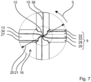
- the top surface 9 has arms 15 having both primary chisel edges 13 and secondary chisel edges 27.
- the exemplary drill head 2 has four arms 15, each having a primary chisel edge 13 and a secondary chisel edge 27.
- the primary chisel edges 13 run from the distal ends 19 of the arms 15 in the direction of the tip 12.
- the chisel edges 13 begin adjacent to the guide surface 26.
- the primary chisel edges 13 run to the tip 12 and thus extend over the entire radial dimension.
- the primary chisel edges 13 are continuous and without interruptions.
- a course of the primary chisel edge 13 can be straight, in particular over the length of the arm 15.
- the primary chisel edge 13 can run parallel to the side surface 24.
- the primary chisel edge 13 rises from the distal end 19 to the tip 12, preferably continuously.
- the primary chisel edge 13 is the line through the highest points of the arm 15 along a radial direction, i.e. from the distal end 19 to the proximal end 18 or to the tip 12.
- the primary chisel edge 13 is the intersection line of a rake face 28 and a flank face 29.
- the rake face 28 leads the flank face 29 in the direction of rotation 5.
- the rake face 28 is inclined relative to the axis of rotation 6 and rises continuously in the direction of impact 8 against the direction of rotation 5.
- the flank face 29 points against the direction of rotation 5 and falls continuously in the direction of impact 8 against the direction of rotation 5.
- a roof angle 30 enclosed between the rake face 28 and the flank face 29 is greater than 45 degrees, preferably greater than 60 degrees and less than 120 degrees. The roof angle 30 ensures effective removal with sufficient service life under chiseling and abrasive conditions.
- the secondary chisel edges 27 are offset in advance of the primary chisel edges 13 in the direction of rotation 5.
- the secondary chisel edges 27 begin at the distal end 19 of the arm 15.
- the chisel edges 27 begin adjacent to the guide surface 26.
- Their radial dimension is less than the radial dimension of the primary chisel edges 13.
- the secondary chisel edges 27 end at the proximal end 18 of the arms 15.
- the secondary chisel edges 27 are continuously less high than the primary chisel edges 13 along the radial direction, ie at any radial distance from the axis of rotation 6 , the primary chisel edge 13 is higher than the secondary chisel edge 27.
- the secondary chisel edge 27 lies on the same arm 15 as the primary chisel edge 13.
- a distance 31 between the primary chisel edge 13 and the secondary chisel edge 13 can be constant approximately over the entire length or at least a large part of the secondary chisel edge 27.
- the secondary chisel edge 27 runs largely parallel to the primary chisel edge 13 of the same arm 15.
- the distance 31 is less than 1/4 of the diameter 20, e.g. less than 1/6 of the diameter 20, preferably greater than 1/8 of the diameter 20.
- the distance 31 is in particular less than the diameter of the body 14.
- the secondary chisel edge 27 runs through local height maxima along a radial direction.
- the secondary chisel edge 27 can rise continuously in the direction of the tip 12.
- the secondary chisel edge 27 is formed, like the primary chisel edge 13 , by the intersection line of a leading surface 32 and a trailing surface 33.
- the leading surface 32 rises in the direction of impact 8 against the direction of rotation 5
- the trailing surface 33 falls in the direction of impact 8 against the direction of rotation 5.
- a roof angle between the two surfaces 32, 33 is greater than 45 degrees, preferably greater than 60 degrees and less than 120 degrees.
- a groove 34 is formed between the primary chisel edge 13 and the secondary chisel edge 13.
- the groove 34 is enclosed by the free surface 29 and the leading surface 32.
- the groove 34 begins at the distal end 19 and preferably runs to the proximal end 18 of the arm 15.
- a length of the groove 34 is equal to the length of the secondary chisel edge 27.
- the groove 34 runs on the arm 15 and is thereby closed against the direction of impact 8 .
- the primary chisel edges 13 can be inclined relative to the secondary chisel edges 27.
- An angle 35 between the primary chisel edge 13 and the secondary chisel edge 27 is small and preferably less than 8 degrees, e.g. less than 5 degrees ( Fig. 5 ).
- the planes of the two chisel edges 13, 27 intersect behind the rotation axis 6 when viewed from the arm 15.
- the drill head 2 can have a four-fold rotational symmetry.
- the diametrically opposed arms 15 are identical and different from the adjacent arms 15.
- one pair of arms 15 has a shorter length than the other pair of arms 15.
- two of the arms 15 can be provided with a primary chisel edge 13 and a secondary chisel edge 27 and the other two arms 15 can only be provided with a primary chisel edge 36.
- Fig. 7 .
- the drill head 2 is preferably made of a sintered material, in particular tungsten carbide.
- the drill head 2 is preferably monolithic, ie the arms 15 and the body 14 are connected to one another without a joining zone, in particular without a weld seam, solder seam or screw connection.
- the helix 3 of the drill 1 has, for example, four helix webs 37.
- the number of helix webs 37 is preferably equal to the number of arms 15.
- the helix webs 37 run along the axis of rotation 6 several times around this axis of rotation 6.
- the helix webs 37 describe a cylindrical envelope whose diameter corresponds to a helix diameter.
- Neighboring helix webs 37 enclose a helix groove 38 between them, which is considered to be geometrically limited in the radial direction by the envelope.
- the drilling material is transported in the helix grooves 38 by the helix webs 37 along the axis of rotation 6.
- a helix pitch 39 is preferably in the range between 35 degrees and 60 degrees, e.g. 45 degrees.
- the exemplary insertion end 4 of the drill 1 is designed for use with hand-held power tools that use turning tools.
- the insertion end 4 has a substantially cylindrical shape.
- the insertion end 4 has two closed locking grooves 40, in which locking elements of the hand-held power tool can engage radially and slide along the axis of rotation 6.
- Grooves 41 aligned longitudinally to the axis of rotation 6 enable a torque to be introduced from the hand-held power tool.
Landscapes
- Engineering & Computer Science (AREA)
- Mining & Mineral Resources (AREA)
- Mechanical Engineering (AREA)
- Life Sciences & Earth Sciences (AREA)
- Geology (AREA)
- Physics & Mathematics (AREA)
- Environmental & Geological Engineering (AREA)
- Fluid Mechanics (AREA)
- General Life Sciences & Earth Sciences (AREA)
- Geochemistry & Mineralogy (AREA)
- Earth Drilling (AREA)
Claims (9)
- Tête de foret (2) destinée à un foret (1), ladite tête de foret comprenant un côté supérieur (9) destiné à extraire une matière minérale,un côté inférieur (10) destiné à la fixation à une queue (3) du foret (1),un axe de rotation (6) s'étendant centralement à travers le côté supérieur (9) et le côté inférieur (10),des bras (15), qui comportent chacun une extrémité proximale (18) par rapport à l'axe de rotation (6) et une extrémité distale (19) par rapport à l'axe de rotation (6), et les côtés supérieurs (9) des bras (15) comportant des bords tranchants primaires (13) qui s'étendent dans la direction allant de l'extrémité proximale (18) à l'extrémité distale (19),l'un au moins des bras (15) du côté supérieur (9) comportant un bord tranchant secondaire (27) qui s'étend le long du bord tranchant primaire (13), le bord tranchant secondaire (27) étant décalé en avant par rapport au bord tranchant primaire (13) du même bras (15) dans un sens de rotation (5) de la tête de foret (2),caractérisée en ce quele bord tranchant primaire (13) et le bord tranchant secondaire (27) délimitent entre eux une rainure (34) du côté supérieur (9) du bras (15), etle bord tranchant primaire (13) fait saillie de manière continue dans la direction d'impact (8) par rapport au bord tranchant secondaire (27) du même bras (15).
- Tête de foret (2) selon la revendication 1, caractérisée en ce que le bord tranchant primaire (13) et le bord tranchant secondaire (27) d'un même bras (15) commencent à l'extrémité distale (19) du bras (15).
- Tête de foret (2) selon l'une des revendications précédentes, caractérisée en ce que le bord tranchant primaire (13) s'étend parallèlement au bord tranchant secondaire (27) du même bras (15).
- Tête de foret (2) selon l'une des revendications précédentes, caractérisée en ce que le bord tranchant primaire (13) se termine au niveau d'une pointe (12) de la tête de foret (2) et le bord tranchant secondaire (27) se termine avant la pointe (12).
- Tête de foret (2) selon l'une des revendications précédentes, caractérisée en ce qu'une ouverture d'évacuation (16) destinée à évacuer la matière forée est disposée entre des bras adjacents (15) dans le sens de rotation (5).
- Tête de foret (2) selon l'une des revendications précédentes, caractérisée en ce qu'un angle (35) formé entre le bord tranchant primaire (13) et le bord tranchant secondaire (27) d'un même bras (15) est inférieur à 8 degrés.
- Tête de foret (2) selon l'une des revendications précédentes, caractérisée en ce que la tête de foret (2) comporte au moins quatre bras (15).
- Tête de foret (2) selon l'une des revendications précédentes, caractérisée en ce que la tête de foret (2) est divisée en un corps (14) et en bras (15), le corps (14) représentant le plus grand cylindre, qui est disposé coaxialement à l'axe de rotation (6) et peut être entièrement inscrit dans la tête de foret (2).
- Foret (1) comprenant une tête de foret (2) selon l'une des revendications précédentes, une queue (3) qui est soudée ou brasée au côté inférieur (10) de la tête de foret (2) et une extrémité d'insertion (4) pourvue d'une rainure de verrouillage fermée.
Applications Claiming Priority (2)
| Application Number | Priority Date | Filing Date | Title |
|---|---|---|---|
| EP16204748.4A EP3336302A1 (fr) | 2016-12-16 | 2016-12-16 | Foret |
| PCT/EP2017/081627 WO2018108656A1 (fr) | 2016-12-16 | 2017-12-06 | Trépan |
Publications (3)
| Publication Number | Publication Date |
|---|---|
| EP3555411A1 EP3555411A1 (fr) | 2019-10-23 |
| EP3555411B1 true EP3555411B1 (fr) | 2025-02-05 |
| EP3555411C0 EP3555411C0 (fr) | 2025-02-05 |
Family
ID=57614147
Family Applications (2)
| Application Number | Title | Priority Date | Filing Date |
|---|---|---|---|
| EP16204748.4A Withdrawn EP3336302A1 (fr) | 2016-12-16 | 2016-12-16 | Foret |
| EP17821501.8A Active EP3555411B1 (fr) | 2016-12-16 | 2017-12-06 | Foret |
Family Applications Before (1)
| Application Number | Title | Priority Date | Filing Date |
|---|---|---|---|
| EP16204748.4A Withdrawn EP3336302A1 (fr) | 2016-12-16 | 2016-12-16 | Foret |
Country Status (3)
| Country | Link |
|---|---|
| EP (2) | EP3336302A1 (fr) |
| PL (1) | PL3555411T3 (fr) |
| WO (1) | WO2018108656A1 (fr) |
Family Cites Families (6)
| Publication number | Priority date | Publication date | Assignee | Title |
|---|---|---|---|---|
| DE19724373A1 (de) * | 1997-06-10 | 1998-12-17 | Hilti Ag | Gesteinsbohrer |
| WO2001068334A1 (fr) * | 2000-03-15 | 2001-09-20 | Kabushiki Kaisha Miyanaga | Trepan |
| DE102004028099A1 (de) | 2004-06-09 | 2005-12-29 | Hilti Ag | Bohrer |
| DE102006020538A1 (de) * | 2006-05-03 | 2007-11-15 | Irwin Industrial Tools Gmbh | Bohrkopf für Bohrwerkzeug und Bohrwerkzeug |
| DE102007000534A1 (de) * | 2007-10-19 | 2009-04-23 | Hilti Aktiengesellschaft | Schlagbohrwerkzeug |
| DE102015220634A1 (de) * | 2015-10-22 | 2017-06-29 | Robert Bosch Gmbh | Bohrwerkzeug |
-
2016
- 2016-12-16 EP EP16204748.4A patent/EP3336302A1/fr not_active Withdrawn
-
2017
- 2017-12-06 WO PCT/EP2017/081627 patent/WO2018108656A1/fr not_active Ceased
- 2017-12-06 EP EP17821501.8A patent/EP3555411B1/fr active Active
- 2017-12-06 PL PL17821501.8T patent/PL3555411T3/pl unknown
Also Published As
| Publication number | Publication date |
|---|---|
| WO2018108656A1 (fr) | 2018-06-21 |
| PL3555411T3 (pl) | 2025-07-07 |
| EP3336302A1 (fr) | 2018-06-20 |
| EP3555411A1 (fr) | 2019-10-23 |
| EP3555411C0 (fr) | 2025-02-05 |
Similar Documents
| Publication | Publication Date | Title |
|---|---|---|
| EP0654580B1 (fr) | Foret héliocoidal | |
| EP0884448B1 (fr) | Trépan de roche avec rainures d'évacuation hélicoidales | |
| EP0778391B1 (fr) | Perceuse rotative hélicoidale à percussion | |
| EP0778100B1 (fr) | Foret héliocoidal de percussion | |
| EP0452255B1 (fr) | Trépan de roche | |
| DE102009003288A1 (de) | Bohrer | |
| EP3445519B1 (fr) | Foret | |
| EP1455978B1 (fr) | Outil de percage par percussion ou par martelage | |
| DE3020284A1 (de) | Wendelbohrer | |
| EP2011958A1 (fr) | Tarière | |
| WO1998054435A1 (fr) | Outil de perçage | |
| EP3555411B1 (fr) | Foret | |
| EP3263254A1 (fr) | Tête de forage | |
| EP1340604A2 (fr) | Foret | |
| DE19730665A1 (de) | Bohrer | |
| EP0778390B1 (fr) | Perceuse rotative hélicoidale à percussion | |
| CH696928A5 (de) | Kernbohrkrone, insbesondere Diamantbohrkrone, mit verbesserter Spülung. | |
| EP3515640B1 (fr) | Foret | |
| EP1188897B1 (fr) | Trépan de forage de roche | |
| DE1291707B (de) | Gesteinsbohrer | |
| DE102011090063B4 (de) | Hammerbohrkrone | |
| EP0965405B1 (fr) | Outil de forage | |
| EP3222377A1 (fr) | Foret | |
| EP0965406B1 (fr) | Outil de forage | |
| EP0726382A2 (fr) | Outil de forage rotatif |
Legal Events
| Date | Code | Title | Description |
|---|---|---|---|
| STAA | Information on the status of an ep patent application or granted ep patent |
Free format text: STATUS: UNKNOWN |
|
| STAA | Information on the status of an ep patent application or granted ep patent |
Free format text: STATUS: THE INTERNATIONAL PUBLICATION HAS BEEN MADE |
|
| PUAI | Public reference made under article 153(3) epc to a published international application that has entered the european phase |
Free format text: ORIGINAL CODE: 0009012 |
|
| STAA | Information on the status of an ep patent application or granted ep patent |
Free format text: STATUS: REQUEST FOR EXAMINATION WAS MADE |
|
| 17P | Request for examination filed |
Effective date: 20190716 |
|
| AK | Designated contracting states |
Kind code of ref document: A1 Designated state(s): AL AT BE BG CH CY CZ DE DK EE ES FI FR GB GR HR HU IE IS IT LI LT LU LV MC MK MT NL NO PL PT RO RS SE SI SK SM TR |
|
| AX | Request for extension of the european patent |
Extension state: BA ME |
|
| DAV | Request for validation of the european patent (deleted) | ||
| DAX | Request for extension of the european patent (deleted) | ||
| STAA | Information on the status of an ep patent application or granted ep patent |
Free format text: STATUS: EXAMINATION IS IN PROGRESS |
|
| 17Q | First examination report despatched |
Effective date: 20220914 |
|
| GRAP | Despatch of communication of intention to grant a patent |
Free format text: ORIGINAL CODE: EPIDOSNIGR1 |
|
| STAA | Information on the status of an ep patent application or granted ep patent |
Free format text: STATUS: GRANT OF PATENT IS INTENDED |
|
| INTG | Intention to grant announced |
Effective date: 20240903 |
|
| GRAS | Grant fee paid |
Free format text: ORIGINAL CODE: EPIDOSNIGR3 |
|
| GRAA | (expected) grant |
Free format text: ORIGINAL CODE: 0009210 |
|
| STAA | Information on the status of an ep patent application or granted ep patent |
Free format text: STATUS: THE PATENT HAS BEEN GRANTED |
|
| AK | Designated contracting states |
Kind code of ref document: B1 Designated state(s): AL AT BE BG CH CY CZ DE DK EE ES FI FR GB GR HR HU IE IS IT LI LT LU LV MC MK MT NL NO PL PT RO RS SE SI SK SM TR |
|
| REG | Reference to a national code |
Ref country code: GB Ref legal event code: FG4D Free format text: NOT ENGLISH |
|
| REG | Reference to a national code |
Ref country code: CH Ref legal event code: EP |
|
| REG | Reference to a national code |
Ref country code: IE Ref legal event code: FG4D Free format text: LANGUAGE OF EP DOCUMENT: GERMAN |
|
| REG | Reference to a national code |
Ref country code: DE Ref legal event code: R096 Ref document number: 502017016680 Country of ref document: DE |
|
| U01 | Request for unitary effect filed |
Effective date: 20250210 |
|
| U07 | Unitary effect registered |
Designated state(s): AT BE BG DE DK EE FI FR IT LT LU LV MT NL PT RO SE SI Effective date: 20250214 |
|
| PG25 | Lapsed in a contracting state [announced via postgrant information from national office to epo] |
Ref country code: RS Free format text: LAPSE BECAUSE OF FAILURE TO SUBMIT A TRANSLATION OF THE DESCRIPTION OR TO PAY THE FEE WITHIN THE PRESCRIBED TIME-LIMIT Effective date: 20250505 |
|
| PG25 | Lapsed in a contracting state [announced via postgrant information from national office to epo] |
Ref country code: ES Free format text: LAPSE BECAUSE OF FAILURE TO SUBMIT A TRANSLATION OF THE DESCRIPTION OR TO PAY THE FEE WITHIN THE PRESCRIBED TIME-LIMIT Effective date: 20250205 |
|
| PG25 | Lapsed in a contracting state [announced via postgrant information from national office to epo] |
Ref country code: IS Free format text: LAPSE BECAUSE OF FAILURE TO SUBMIT A TRANSLATION OF THE DESCRIPTION OR TO PAY THE FEE WITHIN THE PRESCRIBED TIME-LIMIT Effective date: 20250605 Ref country code: NO Free format text: LAPSE BECAUSE OF FAILURE TO SUBMIT A TRANSLATION OF THE DESCRIPTION OR TO PAY THE FEE WITHIN THE PRESCRIBED TIME-LIMIT Effective date: 20250505 |
|
| PG25 | Lapsed in a contracting state [announced via postgrant information from national office to epo] |
Ref country code: HR Free format text: LAPSE BECAUSE OF FAILURE TO SUBMIT A TRANSLATION OF THE DESCRIPTION OR TO PAY THE FEE WITHIN THE PRESCRIBED TIME-LIMIT Effective date: 20250205 |
|
| PG25 | Lapsed in a contracting state [announced via postgrant information from national office to epo] |
Ref country code: GR Free format text: LAPSE BECAUSE OF FAILURE TO SUBMIT A TRANSLATION OF THE DESCRIPTION OR TO PAY THE FEE WITHIN THE PRESCRIBED TIME-LIMIT Effective date: 20250506 |
|
| PG25 | Lapsed in a contracting state [announced via postgrant information from national office to epo] |
Ref country code: SM Free format text: LAPSE BECAUSE OF FAILURE TO SUBMIT A TRANSLATION OF THE DESCRIPTION OR TO PAY THE FEE WITHIN THE PRESCRIBED TIME-LIMIT Effective date: 20250205 |
|
| PG25 | Lapsed in a contracting state [announced via postgrant information from national office to epo] |
Ref country code: CZ Free format text: LAPSE BECAUSE OF FAILURE TO SUBMIT A TRANSLATION OF THE DESCRIPTION OR TO PAY THE FEE WITHIN THE PRESCRIBED TIME-LIMIT Effective date: 20250205 |
|
| PG25 | Lapsed in a contracting state [announced via postgrant information from national office to epo] |
Ref country code: SK Free format text: LAPSE BECAUSE OF FAILURE TO SUBMIT A TRANSLATION OF THE DESCRIPTION OR TO PAY THE FEE WITHIN THE PRESCRIBED TIME-LIMIT Effective date: 20250205 |
|
| PLBE | No opposition filed within time limit |
Free format text: ORIGINAL CODE: 0009261 |
|
| STAA | Information on the status of an ep patent application or granted ep patent |
Free format text: STATUS: NO OPPOSITION FILED WITHIN TIME LIMIT |
|
| REG | Reference to a national code |
Ref country code: CH Ref legal event code: L10 Free format text: ST27 STATUS EVENT CODE: U-0-0-L10-L00 (AS PROVIDED BY THE NATIONAL OFFICE) Effective date: 20251217 |
|
| REG | Reference to a national code |
Ref country code: CH Ref legal event code: U11 Free format text: ST27 STATUS EVENT CODE: U-0-0-U10-U11 (AS PROVIDED BY THE NATIONAL OFFICE) Effective date: 20260101 |
|
| PGFP | Annual fee paid to national office [announced via postgrant information from national office to epo] |
Ref country code: GB Payment date: 20251219 Year of fee payment: 9 |
|
| 26N | No opposition filed |
Effective date: 20251106 |
|
| PGFP | Annual fee paid to national office [announced via postgrant information from national office to epo] |
Ref country code: PL Payment date: 20251127 Year of fee payment: 9 |
|
| U20 | Renewal fee for the european patent with unitary effect paid |
Year of fee payment: 9 Effective date: 20251230 |