EP3555503B2 - Dispositif pour assurer l'étanchéité d'un objet - Google Patents
Dispositif pour assurer l'étanchéité d'un objet Download PDFInfo
- Publication number
- EP3555503B2 EP3555503B2 EP17803939.2A EP17803939A EP3555503B2 EP 3555503 B2 EP3555503 B2 EP 3555503B2 EP 17803939 A EP17803939 A EP 17803939A EP 3555503 B2 EP3555503 B2 EP 3555503B2
- Authority
- EP
- European Patent Office
- Prior art keywords
- sealing body
- sealing
- rigidity
- elements
- sealed
- Prior art date
- Legal status (The legal status is an assumption and is not a legal conclusion. Google has not performed a legal analysis and makes no representation as to the accuracy of the status listed.)
- Active
Links
Images

Classifications
-
- F—MECHANICAL ENGINEERING; LIGHTING; HEATING; WEAPONS; BLASTING
- F16—ENGINEERING ELEMENTS AND UNITS; GENERAL MEASURES FOR PRODUCING AND MAINTAINING EFFECTIVE FUNCTIONING OF MACHINES OR INSTALLATIONS; THERMAL INSULATION IN GENERAL
- F16J—PISTONS; CYLINDERS; SEALINGS
- F16J15/00—Sealings
- F16J15/16—Sealings between relatively-moving surfaces
- F16J15/32—Sealings between relatively-moving surfaces with elastic sealings, e.g. O-rings
- F16J15/3204—Sealings between relatively-moving surfaces with elastic sealings, e.g. O-rings with at least one lip
- F16J15/3228—Sealings between relatively-moving surfaces with elastic sealings, e.g. O-rings with at least one lip formed by deforming a flat ring
-
- F—MECHANICAL ENGINEERING; LIGHTING; HEATING; WEAPONS; BLASTING
- F16—ENGINEERING ELEMENTS AND UNITS; GENERAL MEASURES FOR PRODUCING AND MAINTAINING EFFECTIVE FUNCTIONING OF MACHINES OR INSTALLATIONS; THERMAL INSULATION IN GENERAL
- F16J—PISTONS; CYLINDERS; SEALINGS
- F16J15/00—Sealings
- F16J15/16—Sealings between relatively-moving surfaces
- F16J15/32—Sealings between relatively-moving surfaces with elastic sealings, e.g. O-rings
- F16J15/3244—Sealings between relatively-moving surfaces with elastic sealings, e.g. O-rings with hydrodynamic pumping action
Definitions
- the invention relates to a device for sealing an object to be sealed, in particular for sealing a rotating shaft, with a sealing body which has a sealing side facing the object to be sealed and a rear side facing away from the object to be sealed, according to the type defined in more detail in the preamble of claim 1.
- a similar sealing element for sealing a rotating shaft at a passage opening of a housing part comprising a stiffening part and an elastomer part connected to the stiffening part, which has a first sealing region for a statically sealing fit on the housing part and a second sealing region with a sealing section designed and provided for a sealing fit on the shaft, which comprises a thread-like return structure for returning a leakage fluid into a space to be sealed.
- the DE 10 2010 042 555 A1 describes a radial shaft seal which has a stiffening ring and an elastomer part connected to the stiffening ring, which has a sealing lip with a first sealing section provided with a thread-like return structure for the return of a leakage fluid in a rotating shaft and a second sealing section which has a circular cylinder jacket-shaped sealing surface for gas-tight contact with a stationary shaft, which in turn has a microstructure.
- a radial shaft seal with a stiffening ring and an elastomer part connected to the stiffening ring which has a dynamic sealing lip with a radial sealing lip section and an axial sealing lip section, wherein the axial sealing lip section has a sealing edge for a sealing fit on a shaft, which is arranged on an inner jacket wall of the axial sealing lip section facing the shaft.
- the WO 2012/095227 A1 describes a radial shaft seal with a reinforcing ring and an elastomer part connected to the reinforcing ring, which carries a dynamic sealing lip which has a sealing edge made of PTFE which rests on a shaft sealed by the radial shaft seal.
- a drive shaft of an axial piston machine is known which is sealed by means of a radial shaft sealing system which has a radial shaft sealing ring and a counter-running surface whose surface has a hydrodynamic return structure provided with a hard, diamond-like surface coating.
- a release bearing of a friction clutch designed as a diaphragm spring clutch is in the DE 10 2009 049 466 A1
- This has a bearing interior filled with bearing grease, which is axially closed off with a seal that is rigidly attached to the bearing outer ring and rests with the sealing edge of a sealing lip on a sealing surface of the bearing inner ring.
- the sealing lip of the seal is provided with a ring-shaped return structure that is arranged axially adjacent to the sealing edge and is in operative connection with the associated sealing surface.
- a mechanical seal for sealing the passage of a rotating shaft through a wall is known from EP 0 592 462 B1
- the mechanical seal has return structures that have several return points located at geometrically defined positions.
- the DE 101 09 320 A1 describes a radial shaft seal with a sealing element made of plastic, in particular of PTFE compound, which has a sealing lip, a section of which lies sealingly against the surface of a shaft on the medium side.
- a pressing device is provided on the medium side of the sealing lip, which holds the section of the sealing lip pressed against the surface of the shaft with a radially inward-directed force.
- the US 2014/110904 A1 shows a dynamic lip seal for sealing between a housing and a shaft.
- the seal comprises a sealing lip extending from a sealing body and comprising a shaft contact portion designed to engage with the shaft. Furthermore, spiral grooves are provided with which oil can be pumped in different directions depending on the direction of rotation of the shaft.
- the JP 2000 310341 A describes a seal with a screw-like projection designed to provide a pumping function from an atmospheric side to a side to be sealed.
- the DE 100 00 853 A1 shows a sealing ring which has a sealing lip curved in the direction of the zone to be sealed with an opening on the radial side facing away from the machine unit.
- the EP 0 352 118 A1 The seal described comprises a base portion made of a first material, such as an elastomer; and a liner portion made of a second material, such as PTFE, which forms a sealing contact with a shaft and which has a series of openings or recesses formed therein.
- a first material such as an elastomer
- a liner portion made of a second material, such as PTFE
- the JP H11 351405 A describes a sealing device for sealing between two elements which are rotatable and concentrically arranged relative to each other.
- the JP H08 35564 A describes a manufacturing process for an annular seal.
- the known radial shaft seals are therefore often provided with so-called return structures, which are intended to ensure that fluid carried along by the rotating shaft is axially diverted in the direction of the media side or the side to be sealed, so that the fluid is returned and thus a seal is created in the dynamic state.
- return structures which are intended to ensure that fluid carried along by the rotating shaft is axially diverted in the direction of the media side or the side to be sealed, so that the fluid is returned and thus a seal is created in the dynamic state.
- this principle sometimes works without explicitly created return structures, since rubber material forms these structures itself due to friction.
- the known sealing rings provided with such return structures on the sealing side facing the object to be sealed, or the sealing rings in which the return structures form automatically, are usually made of a rubber-based material.
- the problem with rubber sealing rings, however, is the fact that they become very hot due to the friction with the rotating shaft when the high contact forces are sometimes required and can be damaged.
- sealing rings made of other, particularly more heat-resistant materials such as polytetrafluoroethylene. Examples of this are also described above. Since the seals made of these materials are more thermally and chemically resistant, but also much harder than rubber sealing rings, these return structures do not arise automatically in these sealing rings, but must be incorporated into them, which leads to very high manufacturing and assembly requirements. In addition, the higher hardness of this material can mean that the sealing side or the contact surface may not fit completely against the object to be sealed, even with relatively small geometric deviations from the target state, and therefore optimum sealing is not achieved.
- spiral grooves are sometimes used in such PTFE sealing rings to return the fluid.
- spiral grooves work quite well on rotating shafts, i.e. in the case of dynamic sealing, leaks can occur on stationary shafts, i.e. in the case of static sealing, because the fluid can pass through the spiral grooves from the fluid or media side to the air side.
- the element according to the invention which is arranged on the back of the sealing body and changes the rigidity of the latter, achieves an uneven distribution of the surface pressure in the sealing gap between the sealing body of the device according to the invention and the object to be sealed.
- This uneven distribution of the surface pressure and the pressure differences within the sealing gap that arise in the dynamic state result in very narrow and narrowly tapered gaps between the sealing body and the object to be sealed, through which the fluid carried along by the rotating shaft is deflected in the axial direction and can thus be conveyed back to the fluid or media side.
- the resulting pumping back effect of the deliberately deflected fluid in the direction of the fluid or media side results in a dynamic sealing effect.
- the described gap formation between the sealing body and the object to be sealed can also only occur in the dynamic state, for example when the shaft rotates. This means that a very effective seal can be achieved in dynamic applications with relatively little design effort.
- the solution according to the invention can be used for a wide variety of purposes, as it can be easily adapted to the respective requirements.
- the fluid flow is given a direction away from the peripheral edge.
- obliquely to a longitudinal axis of the sealing body includes both a straight and an arcuate or curved course of the element that changes the rigidity of the sealing body.
- the top view of the sealing system is defined in such a way that the peripheral edge of the sealing body runs at right angles to the longitudinal axis of the sealing body.
- the elements changing the rigidity of the sealing body are formed by a change in the material thickness of the sealing body.
- a particularly relevant design for practical purposes is that the elements that change the rigidity of the sealing body are designed as a depression or as an elevation. Such depressions can be introduced into the sealing body during manufacture and therefore only represent a very low manufacturing effort. Elevations can also be created during manufacture of the sealing body and have the desired effect on the surface pressure between the sealing body and the object to be sealed.
- the fact that the sealing body is essentially smooth on the sealing side according to the invention results in a simple design in terms of manufacturing technology and a good basic seal of the area to be sealed is ensured.
- the term “smooth” refers to a design of the surface on the sealing side of the sealing body that has no embedded or applied structures. In principle, this is a sealing side that is flat or level in its original state, whereby the curvature or bending line of the sealing body resulting from use or assembly is not taken into account.
- oblique to a longitudinal axis of the sealing body means that the elements that change the rigidity of the sealing body run at an angle of between 0.1° and 89.9° or between -89.9° and -0.1° oblique to the longitudinal axis of the sealing body in the plan view. In this way, a desired sealing effect can be achieved by axially deflecting the fluid to be sealed.
- An improvement in the static seal is achieved if the at least one element that changes the rigidity of the sealing body is at a distance from a peripheral edge of the sealing body. In this case, the peripheral edge of the sealing body remains unchanged and ensures effective sealing in all applications. However, this distance is not absolutely necessary and the at least one element that changes the rigidity of the sealing body could also run up to a peripheral edge of the sealing body.
- the at least one depression has a height profile, it can be adapted to different requirements with regard to sealing and the fluid can be conveyed in the desired direction.
- a profile is conceivable both in the circumferential direction and in the axial direction.
- the recess has a depth of 10 to 90%, preferably 30 to 90%, of the material thickness of the sealing body.
- the at least one elevation has a height profile. Furthermore, this allows the fluid to be conveyed in the desired direction. In principle, such a profile is conceivable both in the circumferential direction and in the axial direction.
- a desired sealing effect can be achieved if the increase exceeds the material thickness of the sealing body by 5 to 100%, preferably 25 to 100%.
- the at least one element that changes the rigidity of the sealing body consists of several basic geometric shapes.
- These basic geometric shapes can consist of one or more slopes, arcs, circles or any other conceivable shapes.
- a further advantageous embodiment of the invention can consist in that at least one element changing the rigidity of the sealing body runs in plan view at a positive angle obliquely to the longitudinal axis of the sealing body and at least one element changing the rigidity of the sealing body runs in plan view at a negative angle obliquely to the longitudinal axis of the sealing body is arranged opposite to it. This allows the device according to the invention to be adapted to specific sealing requirements.
- the at least one element which changes the stiffness of the sealing body has two bevels, one of which has a positive angle relative to the longitudinal axis of the sealing body in plan view and the other of which has a negative angle relative to the longitudinal axis of the sealing body in plan view, a seal which is advantageous in certain applications can be achieved.
- the device can be used for two different directions of rotation of a rotating shaft.
- An embodiment of the invention which is particularly advantageous with regard to conveying the fluid in the desired direction is obtained when the at least one element which changes the rigidity of the sealing body widens away from a peripheral edge of the sealing body.
- a parallel course of the two lateral edges of the at least one element which changes the rigidity of the sealing body is also conceivable.
- the sealing body comprises polytetrafluoroethylene. Since problems with the return of the fluid often occur with PTFE seals, the solution according to the invention is particularly interesting for such seals. In principle, the solution according to the invention can also be used with other materials that are usually used for seals. In principle, the solution according to the invention can also be used with other materials that are usually used for seals.
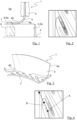
- Fig. 1 shows a device 1 for sealing an object 2 to be sealed, in the present case a shaft 2a rotating about a longitudinal axis 3.
- the device 1 has a sealing body 4 which has a sealing side 4a facing the object 2 to be sealed and partially touching it and a rear side 4b facing away from the object 2 to be sealed.
- the sealing body 4 is held at its end facing away from the object 2 in a component 5 which is only indicated schematically.
- the component 5 can be, for example, a housing in which the rotating shaft 2a is mounted.
- other installation options or types of application of the device 1 are also conceivable.
- the Figures 1, 4 , 6, 8 and 10 The sleeve-like installation situation of the device 1 shown is to be regarded as purely exemplary and the device 1 can be installed or arranged in a wide variety of ways with regard to the installation direction and the arrangement of the same relative to the component 5 and the object 2 in order to achieve the sealing described below.
- all geometric shapes of the sealing body 4 are conceivable in which the circumferential forces on the object 2 arise through an expansion of the sealing body 4.
- the sealing body 4 has at least one element 6 on the rear side 4b which changes the rigidity of the sealing body 4.
- the element 6 which changes the rigidity of the sealing body 4, which is referred to below for the sake of simplicity in part only as element 6, can be designed in various ways, some of which are described below.
- the elements can also be referred to as "back structures" since they are located on the back 4b of the sealing body 4. In principle, an embodiment is also conceivable in which the device has only one of the elements 6.
- the area of the sealing body 4 that is in contact with the object 2 to be sealed experiences stiffness jumps due to the elements 6, which lead to an influence on the surface pressure of the sealing body 4 on the object 2 to be sealed and thus to an influence on the formation of the gap between the sealing body 4 and the object 2 to be sealed. All embodiments therefore have in common that the element 6 is designed in such a way that it changes the surface pressure between the sealing body 4 and the object 2 to be sealed. A changing surface pressure therefore results across the surface of the sealing body 4 that is in contact with the object 2 to be sealed.
- the elements 6 each locally influence the surface pressure of the sealing body 4 on the object 2 to be sealed, so that a certain wedge gap is created in this area or is formed when the shaft 2a rotates due to the drag flow in the circumferential direction of the shaft, through which a fluid that is to be held in a certain area by the device 1 can be conveyed back to this area.
- the fluid can be, for example, oil or another liquid, or possibly also a gas.
- the illustration in the figures shows an area to the left of the device 1. This area forms, for example, the interior 5a of the housing or component 5. All embodiments also have in common that the sealing body 4 is essentially flat on the sealing side 4a. This is not absolutely necessary and the sealing body 4 could also have certain structures on the sealing side 4a.
- the sealing body 4 preferably consists of polytetrafluoroethylene (PTFE).
- PTFE polytetrafluoroethylene
- the at least one element 6 that changes the rigidity of the sealing body 4 could also be used in sealing bodies 4 that consist of other materials, such as elastomers.
- the sealing body 4 could also consist of polyurethane.
- materials or material combinations are NBR, FKM, ACM, VQM, PE, PEEK, each also in combinations and coatings and/or with fillers, such as carbon black, plastics, silicates and the like.
- the elements 6 are arranged such that they are spaced apart from a peripheral edge 7 of the sealing body 4 facing the interior 5a of the component 5. However, this is not absolutely necessary and the elements 6 could also extend to the peripheral edge 7 of the sealing body 4 if necessary. The spacing of the elements 6 from the peripheral edge 7 prevents the fluid from escaping, since the sealing body 4 lies evenly against the object 2 to be sealed in the region of the peripheral edge 7.
- the element 6 is formed by changing the material thickness of the sealing body 4.
- the element 6 that changes the rigidity of the sealing body 4 is designed as a recess 6a.
- the at least one recess 6a or the recesses 6a distributed around the circumference of the sealing body 4 result in a reduction in the rigidity of the sealing body 4 in this area.
- the recess 6a and the resulting reduction in rigidity in the area of the same mean that the respective area between the elements 6 has a higher rigidity.
- the at least one recess 6a can have a height profile, i.e., for example, can reach different levels with regard to its height or depth. Such a profile is conceivable both in the circumferential direction and in the axial direction.
- the recess 6a has a depth of 10 to 90%, in particular 30 to 90% of the material thickness of the sealing body 4. If the sealing body 4 has a material thickness of 2 mm, for example, the depth of the recess 6a is 1 to 1.6 mm. The material of the sealing body 4 remaining in the area of the sealing side 4a, which is in contact with the object 2 to be sealed, is therefore still 0.4 to 1 mm in this case.
- these are purely exemplary details.
- Such recesses 6a forming the elements 6 can be created during the manufacture of the sealing body 4, i.e. during the primary shaping of the same.
- the primary shaping of the sealing body 4 can be carried out, for example, by sintering or injection molding.
- the elements 6 can also be created by embossing, forming, machining or laser processing.
- Fig. 2 the change in the surface pressure between the sealing body 4 and the object 2 to be sealed resulting from the element 6 is shown enlarged using isobars, i.e. lines of equal pressure or, in this case, equal surface pressure.
- Fig. 2 which is characterized by the Fig. 1 isobars resulting from the element 6 shown. From the isobars it can be seen that due to the pressure curve between the sealing body 4 and the object 2 to be sealed, the escaping fluid or fluid tending to escape is diverted in the direction of the interior space 5a. and can be conveyed back. The course of the elements 6 is also shown in the enlargement of Fig. 2 Furthermore, this trend also emerges from Fig.
- the depressions 6a in the top view run obliquely to the longitudinal axis 3 of the rotating shaft 2a, which in the present case also represents the longitudinal axis of the sealing body 4.
- This course of the elements 6 results in a wedge-shaped gap between the sealing body 4 and the object 2 to be sealed, whereby fluid can be conveyed back.
- this design of the elements 6 gives the fluid flow a direction towards the peripheral edge 7. If necessary, it would also be possible to arrange individual elements 6 opposite to the inclination shown, so that the device 1 could be used for two different directions of rotation of the rotating shaft 2a.
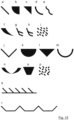
- the at least one element 6 that changes the rigidity of the sealing body 4 consists of several basic geometric shapes. These can consist of one or more bevels, arcs, circles or any other conceivable shapes. Possible but not exclusive geometric shapes are shown in Fig. 15 shown. Positions a - d show simple geometric shapes of how an element 6 that changes the stiffness of the sealing body 4 can be designed. Positions e - h show elements 6 that change the stiffness of the sealing body 4 and consist of composite arcs or composite straight lines. Position i shows elements 6 that change the stiffness of the sealing body 4 and are arranged stochastically distributed with positive or negative angles with respect to the longitudinal axis of the sealing body 4 in the plan view.
- Positions a - i are asymmetrical with respect to the longitudinal axis of the sealing body 4 in the plan view.
- symmetrical elements 6 that change the stiffness of the sealing body 4, as shown in positions j - o, which can be composed of the asymmetrical elements shown as examples.
- Position p shows elements 6 that change the stiffness of the sealing body 4 and are arranged stochastically distributed with positive and negative angles with respect to the longitudinal axis of the sealing body 4 in the plan view.
- Combinations corresponding to the positions q and r are also conceivable, but not exclusive.
- the elements 6 can overlap and be connected to one another and can be formed from a wide variety of geometric shapes.
- the ratio of the height of the resulting sealing gap compared to its length in the direction of the longitudinal axis 3, which depends on the length of the respective element 6 in the direction of the longitudinal axis 3, can be very small and can be, for example, between 1:100 and 1:10000.
- the length of the element 6 in the direction of the longitudinal axis 3 can therefore be several mm.
- Fig. 4 shows the contact area between the device 1 or the sealing body 4 and the object 2 to be sealed or the shaft 2a.
- the back structures described above on the back 4b of the sealing body 4 result in an uneven pressure distribution, which in Fig. 4 is characterized as isobars A.
- the fluid entrained by the rotation of the shaft 2a is axially deflected by the uneven pressure distribution and can be conveyed in the direction of the space to be sealed, in this case the sealing side, which is shown by the arrows marked "B". This ensures the sealing effect in the dynamic state, i.e. when the shaft 2a rotates.
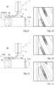
- the element 6 that changes the rigidity of the sealing body 4 is designed as an elevation 6b.
- the at least one elevation 6b or the elevations 6b distributed around the circumference of the sealing body 4 result in an increase in the rigidity of the sealing body 4 in this area.
- a higher surface pressure of the sealing body 4 on the object 2 to be sealed results and the return structures arise between the elements 6.
- the at least one elevation 6b can have a height profile, i.e., for example, reach different levels with regard to its height or depth. Such a profile is conceivable both in the circumferential direction and in the axial direction.
- the elevation 6b also widens away from the peripheral edge 7. Furthermore, the elevations 6b also run obliquely to the longitudinal axis 3 of the rotating shaft 2a, which also represents the longitudinal axis for the sealing body 4.
- the elevation 6b exceeds the material thickness of the sealing body 4 by 5 to 100%, in particular 25 to 100%, so that the desired effect with regard to the change in the surface pressure of the sealing body 4 on the object 2 to be sealed is achieved.
- the height of the elevation 6b is 0.5 to 2.0 mm.
- the material thickness of the sealing body 4 in the area of the elevation 6b is therefore 2.5 mm to 4.0 mm in this case.
- Elevations that exceed the actual material thickness of the sealing body 4 are also conceivable.
- Fig. 6 shows similar to Fig. 2 the isobars, which indicate the surface pressure between the sealing body 4 and the object 2 to be sealed. In this representation, the course of the elevations 6b forming the elements 6 can also be seen.
- the elevations 6b can, similar to the depressions 6a, already be created during the primary shaping of the sealing body 4 described above.
- the elevations 6b could also be created by applying an additional material to the sealing body 4.
- the at least one element 6 which changes the rigidity of the sealing body 4 is formed by a material 6c which is different from the material of the sealing body 4.
- the material 6c is a material with a higher rigidity than the material of the sealing body 4, so that the rigidity of the sealing body 4 is increased in the area of the element 6. This makes it possible to influence the surface pressure between the sealing body 4 and the object 2 to be sealed in a similar way to that achieved by the elevations 6b.
- a recess can be created in the sealing body 4 and the material 6c can be introduced into it.
- the material 6c into the sealing body 4 during production, for example by means of casting, sintering, vulcanization or another suitable process.
- fiber materials can also be used for the material 6c, which can also be introduced into the same during the primary molding.
- the material 6c could also be created by introducing an additional material into the sealing body 4.
- Fig. 8 are analogous to Fig. 2 the isobars are shown, from which the surface pressure between the sealing body 4 and the object 2 to be sealed as well as the course of the elements 6 which widens obliquely to the longitudinal axis 3 and away from the peripheral edge 7 can be determined.
- the element 6 which changes the rigidity of the sealing body 4 is again formed by the elevation 6b, whereby the elevation 6b in this case has the material 6c or consists of the material 6c.
- This results in an increase in rigidity in the area of the element 6 or in the area of the elements 6 arranged distributed around the circumference of the sealing body 4, with the effect on the surface pressure between the sealing body 4 and the object 2 to be sealed, as already described above.
- the height of the elevation 6b can possibly be reduced.
- Fig. 10 the isobars representing the surface pressure between the sealing body 4 and the object 2 to be sealed are also shown and the course of the elements 6, which here too is designed to be oblique to the longitudinal axis 3 and widens away from the peripheral edge 7, is again recognizable.
- the Figures 11 to 13 The device 1 shown in FIG. 1, which does not belong to the invention, is similar to that according to the Figures 7 and 8 , since the element 6 that changes the rigidity of the sealing body 4 is in turn formed by the material 6c that is different from the material of the sealing body 4. Depending on the material used, a reduction or an increase in the rigidity of the sealing body 4 can be achieved in the respective area. Using a material 6c with a lower rigidity than the material of the sealing body 4 results in a reduction in the rigidity in the area of the respective element 6. In contrast, using a material 6c with a higher rigidity than the material of the sealing body 4 results in an increase in the rigidity in the area of the respective element 6.
- Fig. 12 the case of an increase in stiffness and thus an increase in the surface pressure between the sealing body 4 and the object 2 to be sealed
- Fig. 13 shows the case of a reduction in stiffness and thus a reduction in the surface pressure between the sealing body 4 and the object 2 to be sealed.
- the elements 6 widen away from the peripheral edge 7 and are also arranged obliquely to the longitudinal axis 3.
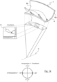
- Fig. 14 shows the device Fig. 3 in a representation in which the oblique course of the recesses 6a to the longitudinal axis 3 of the rotating shaft 2a, which also forms the longitudinal axis of the sealing body 4, is again made clearer.
- the top view of the sealing system is defined in such a way that the peripheral edge of the sealing body 4 runs at right angles to the longitudinal axis of the sealing body 4. Furthermore, this figure also shows the definition of the angle of the inclination explained above with respect to the longitudinal axis of the sealing body 4.
- the representation of Fig. 14 can of course be easily transferred to the case of using the elevation 6b as the element 6 changing the stiffness of the sealing body 4.
- the at least one element 6 which changes the rigidity of the sealing body 4 preferably extends in plan view at an angle between 0.1° and 89.9° or between -89.9° and -0.1° obliquely to the longitudinal axis of the sealing body 4.
- At least one element 6 changing the rigidity of the sealing body 4 can run in the top view at a positive angle obliquely to the longitudinal axis of the sealing body 4 and at least one element 6 changing the rigidity of the sealing body 4 can be arranged in the top view at a negative angle obliquely to the longitudinal axis of the sealing body opposite thereto.
- the at least one element 6 changing the rigidity of the sealing body 4 has two bevels, one of which has a positive angle relative to the longitudinal axis of the sealing body 4 in plan view and the other of which has a negative angle relative to the longitudinal axis of the sealing body 4 in plan view.
- Embodiments of the device 1 not shown in the figures but easily conceivable are also rotating sealing rings and externally sealing rings, i.e. rings that seal against the component 5 or the housing. Another embodiment could be designed to seal axially. An improved sealing effect through the indirect structuring is also conceivable in the case of translational movements.
- the sealing bodies 4 can be manufactured using a wide variety of manufacturing processes.
- the primary forming processes include sintering, casting, e.g. injection molding, vulcanization, exposure, etching and polymerization as well as all rapid prototyping and additive processes.
- the sealing rings can be formed by embossing, stamping, forging, deep-drawing, blow molding or pressing.
- Possible machining processes include milling, drilling, lasering, cutting, gluing and punching.
- Possible joining processes are gluing, laminating, plating, soldering or welding.
- the operating principle of the device 1 can be implemented in particular by removing material, adding material, redistributing material, e.g. by embossing, changing material, e.g. by reinforcing, softening, using fillers, fabric reinforcement, foam structure, the use of different materials, e.g. in a laminate, and/or the action of external forces, e.g. springs or compression bodies.
Landscapes
- Engineering & Computer Science (AREA)
- General Engineering & Computer Science (AREA)
- Mechanical Engineering (AREA)
- Physics & Mathematics (AREA)
- Fluid Mechanics (AREA)
- Sealing Devices (AREA)
- Sealing With Elastic Sealing Lips (AREA)
Claims (8)
- Dispositif (1) pour étanchéifier un objet à étanchéifier (2), en particulier pour étanchéifier un arbre rotatif (2a) comprenant un corps d'étanchéité (4) qui présente une face d'étanchéité (4a) tournée vers l'objet à étanchéifier (2) et une face arrière (4b) opposée à l'objet à étanchéifier (2),dans lequel le corps d'étanchéité (4) présente sur la face arrière (4b) au moins un élément (6) qui modifie la rigidité du corps d'étanchéité (4) et qui modifie la pression superficielle entre le corps d'étanchéité (4) et l'objet à étanchéifier (2), et dans lequel ledit au moins un élément (6) qui modifie la rigidité du corps d'étanchéité (4) s'étend de manière oblique par rapport à un axe longitudinal du corps d'étanchéité (4), dans lequelplusieurs éléments (6) qui modifient la rigidité du corps d'étanchéité (4) sont disposés de façon répartie autour de la périphérie du corps d'étanchéité (4), dans lequel les éléments (6) qui modifient la rigidité du corps d'étanchéité (4) sont réalisés par une modification de l'épaisseur de matériau du corps d'étanchéité (4), dans lequel les éléments (6) qui modifient la rigidité du corps d'étanchéité (4) sont réalisés sous la forme d'un creux (6a) ou d'une élévation (6b) et dans lequel le corps d'étanchéité (4) est réalisé de manière sensiblement lisse sur la face d'étanchéité (4a),caractérisé en ce que les éléments (6) qui modifient la rigidité du corps d'étanchéité (4) s'étendent dans la vue en élévation selon un angle qui est compris entre 0,1° et 89,9° ou entre -89,9° et -0,1° de manière oblique par rapport à l'axe longitudinal du corps d'étanchéité (4).
- Dispositif selon la revendication 1, caractérisé en ce que les éléments (6) qui modifient la rigidité du corps d'étanchéité (4) présentent une certaine distance par rapport à un bord périphérique (7) du corps d'étanchéité (4).
- Dispositif selon la revendication 1, caractérisé en ce que ledit au moins un creux (6a) et/ou ladite au moins une élévation (6b) présente(nt) une variation de hauteur.
- Dispositif selon la revendication 1 ou 3, caractérisé en ce que le creux (6a) présente une profondeur dont la grandeur est comprise entre 10 % et 90 %, de préférence entre 30 % et 90 % de l'épaisseur de matériau du corps d'étanchéité (4), et/ou en ce que l'élévation (6b) dépasse l'épaisseur de matériau du corps d'étanchéité (4) de 5 % à 100 %, de préférence de 25 % à 100 %.
- Dispositif selon l'une quelconque des revendications 1 à 4, caractérisé en ce qu'au moins un élément (6) qui modifie la rigidité du corps d'étanchéité (4) s'étend dans la vue en élévation avec un angle positif de manière oblique par rapport à l'axe longitudinal du corps d'étanchéité (4) et au moins un élément (6) qui modifie la rigidité du corps d'étanchéité (4) est disposé dans la vue en élévation à l'opposé de celui-ci avec un angle négatif de manière oblique par rapport à l'axe longitudinal du corps d'étanchéité (4).
- Dispositif selon l'une quelconque des revendications 1 à 5, caractérisé en ce que les éléments (6) qui modifient la rigidité du corps d'étanchéité (4) présentent deux chanfreins, dont l'un présente dans la vue en élévation un angle positif par rapport à l'axe longitudinal du corps d'étanchéité (4) et dont l'autre présente un angle négatif dans la vue en élévation par rapport à l'axe longitudinal du corps d'étanchéité (4).
- Dispositif selon l'une quelconque des revendications 1 à 6, caractérisé en ce qu'au moins l'un des éléments (6) qui modifient la rigidité du corps d'étanchéité (4), qui sont disposés de façon répartie autour de la périphérie du corps d'étanchéité (4), s'étend dans la vue en élévation dans une direction opposée par rapport aux autres éléments (6) qui modifient la rigidité du corps d'étanchéité (4) dans la vue en élévation de manière oblique par rapport à l'axe longitudinal du corps d'étanchéité (4).
- Dispositif selon l'une quelconque des revendications 1 à 7, caractérisé en ce que les éléments (6) qui modifient la rigidité du corps d'étanchéité (4) s'élargissent à l'écart d'un bord périphérique (7) du corps d'étanchéité (4).
Applications Claiming Priority (2)
| Application Number | Priority Date | Filing Date | Title |
|---|---|---|---|
| DE102016124457.0A DE102016124457B4 (de) | 2016-12-15 | 2016-12-15 | Vorrichtung zur Abdichtung eines Gegenstands |
| PCT/EP2017/080186 WO2018108478A1 (fr) | 2016-12-15 | 2017-11-23 | Dispositif pour assurer l'étanchéité d'un objet |
Publications (3)
| Publication Number | Publication Date |
|---|---|
| EP3555503A1 EP3555503A1 (fr) | 2019-10-23 |
| EP3555503B1 EP3555503B1 (fr) | 2021-08-04 |
| EP3555503B2 true EP3555503B2 (fr) | 2024-10-02 |
Family
ID=60450663
Family Applications (1)
| Application Number | Title | Priority Date | Filing Date |
|---|---|---|---|
| EP17803939.2A Active EP3555503B2 (fr) | 2016-12-15 | 2017-11-23 | Dispositif pour assurer l'étanchéité d'un objet |
Country Status (8)
| Country | Link |
|---|---|
| US (1) | US20210277998A1 (fr) |
| EP (1) | EP3555503B2 (fr) |
| JP (1) | JP6936321B2 (fr) |
| KR (2) | KR102609391B1 (fr) |
| CN (1) | CN110088514B (fr) |
| DE (1) | DE102016124457B4 (fr) |
| DK (1) | DK3555503T4 (fr) |
| WO (1) | WO2018108478A1 (fr) |
Families Citing this family (1)
| Publication number | Priority date | Publication date | Assignee | Title |
|---|---|---|---|---|
| DE102017208574A1 (de) * | 2017-05-19 | 2018-11-22 | Trelleborg Sealing Solutions Germany Gmbh | Rotationsdichtungsanordnung unt Rotationsdichtung mit Rückförderfunktion |
Citations (8)
| Publication number | Priority date | Publication date | Assignee | Title |
|---|---|---|---|---|
| DE655777C (de) † | 1936-02-08 | 1938-01-22 | Kupfer Asbest Co | Einbaufertiger Wellendichtungsring mit einer in einem mehrteiligen Gehaeuse eingefassten Dichtungsmanschette von winkligem Querschnitt mit einer Schraubenfeder zum Andruecken |
| US3515395A (en) † | 1966-09-06 | 1970-06-02 | Gen Motors Corp | Unidirectional pumping seal |
| US3861691A (en) † | 1971-12-16 | 1975-01-21 | Texacone Co | Packing member |
| DE2556992C2 (de) † | 1975-12-18 | 1980-04-24 | Goetze Ag, 5093 Burscheid | Wellendichtring |
| DE3501065A1 (de) † | 1985-01-15 | 1986-07-17 | Freudenberg, Carl, 6940 Weinheim | Radialwellendichtring |
| DE19740821A1 (de) † | 1997-09-17 | 1999-03-18 | Kaco Gmbh Co | Radialwellendichtung |
| JP2005003055A (ja) † | 2003-06-10 | 2005-01-06 | Mitsubishi Cable Ind Ltd | 回転軸シール |
| JP2007162801A (ja) † | 2005-12-13 | 2007-06-28 | Mitsubishi Cable Ind Ltd | 回転軸シール |
Family Cites Families (42)
| Publication number | Priority date | Publication date | Assignee | Title |
|---|---|---|---|---|
| US2818287A (en) * | 1955-04-20 | 1957-12-31 | Greene Tweed & Co Inc | Annular seals |
| IT1016411B (it) * | 1973-08-03 | 1977-05-30 | Freudenberg C | Perfezionamenti nelle guarnizioni di tenuta in particolare per alberi rotanti |
| FR2295319A1 (fr) * | 1974-10-21 | 1976-07-16 | Paulstra Sa | Perfectionnements apportes aux joints d'etancheite ou analogues |
| US4026565A (en) * | 1975-03-10 | 1977-05-31 | Parker-Hannifin Corporation | Sealed static joint and gasket therefor |
| GB2220994B (en) * | 1988-07-21 | 1993-01-13 | Woodville Polymer Eng | Hydrodynamic shaft seals |
| DE4209484A1 (de) | 1991-06-12 | 1993-10-21 | Heinz Konrad Prof Dr I Mueller | Gleitringdichtung mit Rückförderwirkung |
| US5452494A (en) * | 1994-05-05 | 1995-09-26 | Osram Sylvania Inc. | Sealing grommet |
| JPH0835564A (ja) * | 1994-07-22 | 1996-02-06 | Koyo Seiko Co Ltd | 環状板シールおよびその製法 |
| JP3971802B2 (ja) * | 1996-07-17 | 2007-09-05 | 株式会社豊田自動織機 | 圧縮機の軸封構造 |
| IL121796A (en) * | 1997-09-18 | 2001-06-14 | Krausz Metal Ind Ltd | Seal for coupling and connecting means |
| DE69932000T2 (de) * | 1998-04-30 | 2007-05-24 | Krausz Metal Industries, Ltd. | Universelle Rohrverbindung mit einem Dichtungselement |
| JP3785809B2 (ja) * | 1998-06-04 | 2006-06-14 | Nok株式会社 | 密封装置 |
| JP4411685B2 (ja) | 1999-04-27 | 2010-02-10 | Nok株式会社 | 密封装置 |
| SE519239C2 (sv) * | 1999-05-31 | 2003-02-04 | Enebacken Skrea Ab | Tätningsanordning för avtätning av en av två mot varandra vända tätningsytor bildad fog |
| DE10000853A1 (de) * | 2000-01-12 | 2001-08-02 | Freudenberg Carl Fa | Dichtungsanordnung |
| DE10063970B4 (de) * | 2000-12-20 | 2004-11-25 | Carl Freudenberg Kg | Lippendichtring |
| DE10102077A1 (de) * | 2001-01-18 | 2002-08-01 | Freudenberg Carl Kg | Dichtungsanordnung |
| DE10109320C2 (de) | 2001-02-27 | 2003-07-10 | Bruss Dichtungstechnik | Radialwellendichtring |
| JP2003035373A (ja) | 2001-07-23 | 2003-02-07 | Toyota Industries Corp | 軸封装置及び該軸封装置を備えた圧縮機、軸封方法 |
| JP4292396B2 (ja) * | 2003-09-12 | 2009-07-08 | Nok株式会社 | 密封装置 |
| US7100924B2 (en) * | 2004-01-15 | 2006-09-05 | Federal-Mogul Worldwide, Inc. | Elastomeric hinged seal |
| JP2005273691A (ja) * | 2004-03-23 | 2005-10-06 | Nok Corp | シールリップによる軸封構造 |
| IL164194A (en) * | 2004-09-21 | 2009-05-04 | Eliezer Krausz | Gasket for pipe |
| US7731884B2 (en) * | 2004-12-08 | 2010-06-08 | Advanced Elastomer Systems, L.P. | Molded gasket and method of making |
| DE102005037568A1 (de) * | 2005-08-09 | 2007-03-15 | Federal-Mogul Sealing Systems Bretten Gmbh | Elastomer-Wellendichtring |
| US7494130B2 (en) * | 2006-02-13 | 2009-02-24 | Freudenberg-Nok General Partnership | Bi-directional pattern for dynamic seals |
| DE102006058699A1 (de) | 2006-12-13 | 2008-06-26 | Ab Skf | Anordnung |
| DE102007036625B4 (de) | 2007-08-02 | 2013-10-17 | Ab Skf | Dichtelement |
| AT505550B1 (de) * | 2007-10-31 | 2009-02-15 | Hoerbiger Kompressortech Hold | Mehrteiliger packungsring |
| US8820800B2 (en) * | 2007-11-16 | 2014-09-02 | Advanced Drainage Systems, Inc. | Multi-wall corrugated pipe couplings and methods |
| US7891670B2 (en) * | 2008-02-01 | 2011-02-22 | Freudenberg-Nok General Partnership | Multi-directional shaft seal |
| KR101260574B1 (ko) * | 2008-03-13 | 2013-05-06 | 닛폰 바루카 고교 가부시키가이샤 | 실재 |
| DE102009049466A1 (de) | 2009-10-15 | 2011-04-21 | Schaeffler Technologies Gmbh & Co. Kg | Ausrücklager einer Reibungskupplung |
| DE102010026157A1 (de) | 2010-07-06 | 2012-01-12 | Robert Bosch Gmbh | Hydrostatische Maschine, insbesondere Axialkolbenmaschine |
| DE102010042555B4 (de) | 2010-10-18 | 2015-10-08 | Aktiebolaget Skf | Radialwellendichtring |
| DE102010061819A1 (de) | 2010-11-24 | 2012-05-24 | Aktiebolaget Skf | Radialwellendichtring |
| DE102011002491A1 (de) | 2011-01-11 | 2012-07-12 | Aktiebolaget Skf | Radialwellendichtring |
| US8528945B2 (en) * | 2012-01-30 | 2013-09-10 | Sensus Usa Inc. | Split-ring gland pipe coupling with corrugated armor and annular gasket having pressure assist slot |
| DE102012001226A1 (de) * | 2012-01-19 | 2013-07-25 | Kaco Gmbh + Co. Kg | Wellendichtung, insbesondere Radialwellendichtung |
| US9310002B2 (en) * | 2012-06-27 | 2016-04-12 | Eliezer Krausz Industrial Development Ltd. | Multilayer hydraulic seal assembly for clamp |
| US8919782B2 (en) * | 2012-10-19 | 2014-12-30 | Freudenberg-Nok General Partnership | Dynamic lay down lip seal with bidirectional pumping feature |
| DE102013207029B4 (de) | 2013-04-18 | 2016-05-04 | Aktiebolaget Skf | Radialwellen-Dichtungsanordnung |
-
2016
- 2016-12-15 DE DE102016124457.0A patent/DE102016124457B4/de active Active
-
2017
- 2017-11-23 KR KR1020237002904A patent/KR102609391B1/ko active Active
- 2017-11-23 CN CN201780077537.XA patent/CN110088514B/zh active Active
- 2017-11-23 DK DK17803939.2T patent/DK3555503T4/da active
- 2017-11-23 KR KR1020197016668A patent/KR20190094365A/ko not_active Ceased
- 2017-11-23 US US16/468,267 patent/US20210277998A1/en not_active Abandoned
- 2017-11-23 JP JP2019531987A patent/JP6936321B2/ja active Active
- 2017-11-23 EP EP17803939.2A patent/EP3555503B2/fr active Active
- 2017-11-23 WO PCT/EP2017/080186 patent/WO2018108478A1/fr not_active Ceased
Patent Citations (8)
| Publication number | Priority date | Publication date | Assignee | Title |
|---|---|---|---|---|
| DE655777C (de) † | 1936-02-08 | 1938-01-22 | Kupfer Asbest Co | Einbaufertiger Wellendichtungsring mit einer in einem mehrteiligen Gehaeuse eingefassten Dichtungsmanschette von winkligem Querschnitt mit einer Schraubenfeder zum Andruecken |
| US3515395A (en) † | 1966-09-06 | 1970-06-02 | Gen Motors Corp | Unidirectional pumping seal |
| US3861691A (en) † | 1971-12-16 | 1975-01-21 | Texacone Co | Packing member |
| DE2556992C2 (de) † | 1975-12-18 | 1980-04-24 | Goetze Ag, 5093 Burscheid | Wellendichtring |
| DE3501065A1 (de) † | 1985-01-15 | 1986-07-17 | Freudenberg, Carl, 6940 Weinheim | Radialwellendichtring |
| DE19740821A1 (de) † | 1997-09-17 | 1999-03-18 | Kaco Gmbh Co | Radialwellendichtung |
| JP2005003055A (ja) † | 2003-06-10 | 2005-01-06 | Mitsubishi Cable Ind Ltd | 回転軸シール |
| JP2007162801A (ja) † | 2005-12-13 | 2007-06-28 | Mitsubishi Cable Ind Ltd | 回転軸シール |
Also Published As
| Publication number | Publication date |
|---|---|
| JP2020514632A (ja) | 2020-05-21 |
| WO2018108478A1 (fr) | 2018-06-21 |
| CN110088514B (zh) | 2021-09-14 |
| JP6936321B2 (ja) | 2021-09-15 |
| DK3555503T3 (da) | 2021-10-11 |
| EP3555503B1 (fr) | 2021-08-04 |
| DE102016124457A1 (de) | 2018-06-21 |
| US20210277998A1 (en) | 2021-09-09 |
| KR20190094365A (ko) | 2019-08-13 |
| EP3555503A1 (fr) | 2019-10-23 |
| DK3555503T4 (da) | 2024-11-04 |
| KR102609391B1 (ko) | 2023-12-01 |
| CN110088514A (zh) | 2019-08-02 |
| KR20230020005A (ko) | 2023-02-09 |
| DE102016124457B4 (de) | 2025-03-27 |
Similar Documents
| Publication | Publication Date | Title |
|---|---|---|
| EP3625484B1 (fr) | Arrangement de garniture d'étanchéité rotative et garniture d'étanchéité rotative avec fonction de refoulement | |
| EP2988035B1 (fr) | Joint d'etancheite et son utilisation | |
| DE3244209C2 (de) | Dichtung zum Abdichten gegen hydraulische Medien, vorzugsweise Dichtabstreifelement | |
| EP2886896A2 (fr) | Palier à roulement doté d'une unité d'étanchéité pour palier à roulement | |
| DE102013012044B4 (de) | Dichtungsanordnung und Dichtring | |
| EP1992851B1 (fr) | Dispositif d'étanchéité | |
| EP0798498B1 (fr) | Joint à lèvre radiale avec effet de refoulement indépendant du sens de rotation | |
| EP3299682B1 (fr) | Joint d'étanchéité et son utilisation | |
| DE10305173A1 (de) | Dichtring und Dichtungsanordnung, umfassend zwei solcher Dichtringe | |
| DE3016231C2 (de) | Dichtungsanordnung | |
| EP3555503B2 (fr) | Dispositif pour assurer l'étanchéité d'un objet | |
| EP4067706B1 (fr) | Bague d'étanchéité | |
| EP3553352B1 (fr) | Joint radial d'étanchéité d'arbre | |
| EP1162394B1 (fr) | Elément d'étanchéité pour ensembles piston-cylindre hydrauliques | |
| DE102017206770A1 (de) | Dichtungsanordnung | |
| WO2017207146A1 (fr) | Joint à gorge et son procédé de fabrication | |
| EP1998089B1 (fr) | Agencement de joint, bague d'étanchéité et leur utilisation | |
| DE19726433C2 (de) | Dichtungsanordnung | |
| DE102011003934A1 (de) | Dichtungselement für Kreiskolbenmaschine | |
| DE19821146A1 (de) | Radialwellendichtring | |
| DE102008026599B4 (de) | Schwenkmotor mit Radialwellendichtungssystem | |
| DE202009010326U1 (de) | Anordnung zur Abdichtung von Leitungen, Armaturen oder Aggregaten | |
| EP3339654B1 (fr) | Pompe centrifuge | |
| EP2861897B2 (fr) | Joint d'étanchéité à bague de glissement | |
| DE102013217397A1 (de) | Dichtung |
Legal Events
| Date | Code | Title | Description |
|---|---|---|---|
| STAA | Information on the status of an ep patent application or granted ep patent |
Free format text: STATUS: UNKNOWN |
|
| STAA | Information on the status of an ep patent application or granted ep patent |
Free format text: STATUS: THE INTERNATIONAL PUBLICATION HAS BEEN MADE |
|
| TPAC | Observations filed by third parties |
Free format text: ORIGINAL CODE: EPIDOSNTIPA |
|
| PUAI | Public reference made under article 153(3) epc to a published international application that has entered the european phase |
Free format text: ORIGINAL CODE: 0009012 |
|
| STAA | Information on the status of an ep patent application or granted ep patent |
Free format text: STATUS: REQUEST FOR EXAMINATION WAS MADE |
|
| 17P | Request for examination filed |
Effective date: 20190704 |
|
| AK | Designated contracting states |
Kind code of ref document: A1 Designated state(s): AL AT BE BG CH CY CZ DE DK EE ES FI FR GB GR HR HU IE IS IT LI LT LU LV MC MK MT NL NO PL PT RO RS SE SI SK SM TR |
|
| AX | Request for extension of the european patent |
Extension state: BA ME |
|
| DAV | Request for validation of the european patent (deleted) | ||
| DAX | Request for extension of the european patent (deleted) | ||
| STAA | Information on the status of an ep patent application or granted ep patent |
Free format text: STATUS: EXAMINATION IS IN PROGRESS |
|
| 17Q | First examination report despatched |
Effective date: 20200602 |
|
| GRAP | Despatch of communication of intention to grant a patent |
Free format text: ORIGINAL CODE: EPIDOSNIGR1 |
|
| STAA | Information on the status of an ep patent application or granted ep patent |
Free format text: STATUS: GRANT OF PATENT IS INTENDED |
|
| INTG | Intention to grant announced |
Effective date: 20210527 |
|
| GRAS | Grant fee paid |
Free format text: ORIGINAL CODE: EPIDOSNIGR3 |
|
| GRAA | (expected) grant |
Free format text: ORIGINAL CODE: 0009210 |
|
| STAA | Information on the status of an ep patent application or granted ep patent |
Free format text: STATUS: THE PATENT HAS BEEN GRANTED |
|
| AK | Designated contracting states |
Kind code of ref document: B1 Designated state(s): AL AT BE BG CH CY CZ DE DK EE ES FI FR GB GR HR HU IE IS IT LI LT LU LV MC MK MT NL NO PL PT RO RS SE SI SK SM TR |
|
| REG | Reference to a national code |
Ref country code: GB Ref legal event code: FG4D Free format text: NOT ENGLISH |
|
| REG | Reference to a national code |
Ref country code: AT Ref legal event code: REF Ref document number: 1417298 Country of ref document: AT Kind code of ref document: T Effective date: 20210815 |
|
| REG | Reference to a national code |
Ref country code: CH Ref legal event code: EP |
|
| REG | Reference to a national code |
Ref country code: DE Ref legal event code: R096 Ref document number: 502017011121 Country of ref document: DE |
|
| REG | Reference to a national code |
Ref country code: IE Ref legal event code: FG4D Free format text: LANGUAGE OF EP DOCUMENT: GERMAN |
|
| REG | Reference to a national code |
Ref country code: DK Ref legal event code: T3 Effective date: 20211007 |
|
| REG | Reference to a national code |
Ref country code: LT Ref legal event code: MG9D |
|
| REG | Reference to a national code |
Ref country code: NL Ref legal event code: MP Effective date: 20210804 |
|
| PG25 | Lapsed in a contracting state [announced via postgrant information from national office to epo] |
Ref country code: SE Free format text: LAPSE BECAUSE OF FAILURE TO SUBMIT A TRANSLATION OF THE DESCRIPTION OR TO PAY THE FEE WITHIN THE PRESCRIBED TIME-LIMIT Effective date: 20210804 Ref country code: RS Free format text: LAPSE BECAUSE OF FAILURE TO SUBMIT A TRANSLATION OF THE DESCRIPTION OR TO PAY THE FEE WITHIN THE PRESCRIBED TIME-LIMIT Effective date: 20210804 Ref country code: HR Free format text: LAPSE BECAUSE OF FAILURE TO SUBMIT A TRANSLATION OF THE DESCRIPTION OR TO PAY THE FEE WITHIN THE PRESCRIBED TIME-LIMIT Effective date: 20210804 Ref country code: ES Free format text: LAPSE BECAUSE OF FAILURE TO SUBMIT A TRANSLATION OF THE DESCRIPTION OR TO PAY THE FEE WITHIN THE PRESCRIBED TIME-LIMIT Effective date: 20210804 Ref country code: FI Free format text: LAPSE BECAUSE OF FAILURE TO SUBMIT A TRANSLATION OF THE DESCRIPTION OR TO PAY THE FEE WITHIN THE PRESCRIBED TIME-LIMIT Effective date: 20210804 Ref country code: BG Free format text: LAPSE BECAUSE OF FAILURE TO SUBMIT A TRANSLATION OF THE DESCRIPTION OR TO PAY THE FEE WITHIN THE PRESCRIBED TIME-LIMIT Effective date: 20211104 Ref country code: LT Free format text: LAPSE BECAUSE OF FAILURE TO SUBMIT A TRANSLATION OF THE DESCRIPTION OR TO PAY THE FEE WITHIN THE PRESCRIBED TIME-LIMIT Effective date: 20210804 Ref country code: NO Free format text: LAPSE BECAUSE OF FAILURE TO SUBMIT A TRANSLATION OF THE DESCRIPTION OR TO PAY THE FEE WITHIN THE PRESCRIBED TIME-LIMIT Effective date: 20211104 Ref country code: PT Free format text: LAPSE BECAUSE OF FAILURE TO SUBMIT A TRANSLATION OF THE DESCRIPTION OR TO PAY THE FEE WITHIN THE PRESCRIBED TIME-LIMIT Effective date: 20211206 |
|
| PG25 | Lapsed in a contracting state [announced via postgrant information from national office to epo] |
Ref country code: PL Free format text: LAPSE BECAUSE OF FAILURE TO SUBMIT A TRANSLATION OF THE DESCRIPTION OR TO PAY THE FEE WITHIN THE PRESCRIBED TIME-LIMIT Effective date: 20210804 Ref country code: LV Free format text: LAPSE BECAUSE OF FAILURE TO SUBMIT A TRANSLATION OF THE DESCRIPTION OR TO PAY THE FEE WITHIN THE PRESCRIBED TIME-LIMIT Effective date: 20210804 Ref country code: GR Free format text: LAPSE BECAUSE OF FAILURE TO SUBMIT A TRANSLATION OF THE DESCRIPTION OR TO PAY THE FEE WITHIN THE PRESCRIBED TIME-LIMIT Effective date: 20211105 |
|
| PG25 | Lapsed in a contracting state [announced via postgrant information from national office to epo] |
Ref country code: NL Free format text: LAPSE BECAUSE OF FAILURE TO SUBMIT A TRANSLATION OF THE DESCRIPTION OR TO PAY THE FEE WITHIN THE PRESCRIBED TIME-LIMIT Effective date: 20210804 |
|
| REG | Reference to a national code |
Ref country code: DE Ref legal event code: R026 Ref document number: 502017011121 Country of ref document: DE |
|
| PLBI | Opposition filed |
Free format text: ORIGINAL CODE: 0009260 |
|
| PG25 | Lapsed in a contracting state [announced via postgrant information from national office to epo] |
Ref country code: SM Free format text: LAPSE BECAUSE OF FAILURE TO SUBMIT A TRANSLATION OF THE DESCRIPTION OR TO PAY THE FEE WITHIN THE PRESCRIBED TIME-LIMIT Effective date: 20210804 Ref country code: SK Free format text: LAPSE BECAUSE OF FAILURE TO SUBMIT A TRANSLATION OF THE DESCRIPTION OR TO PAY THE FEE WITHIN THE PRESCRIBED TIME-LIMIT Effective date: 20210804 Ref country code: RO Free format text: LAPSE BECAUSE OF FAILURE TO SUBMIT A TRANSLATION OF THE DESCRIPTION OR TO PAY THE FEE WITHIN THE PRESCRIBED TIME-LIMIT Effective date: 20210804 Ref country code: EE Free format text: LAPSE BECAUSE OF FAILURE TO SUBMIT A TRANSLATION OF THE DESCRIPTION OR TO PAY THE FEE WITHIN THE PRESCRIBED TIME-LIMIT Effective date: 20210804 Ref country code: CZ Free format text: LAPSE BECAUSE OF FAILURE TO SUBMIT A TRANSLATION OF THE DESCRIPTION OR TO PAY THE FEE WITHIN THE PRESCRIBED TIME-LIMIT Effective date: 20210804 Ref country code: AL Free format text: LAPSE BECAUSE OF FAILURE TO SUBMIT A TRANSLATION OF THE DESCRIPTION OR TO PAY THE FEE WITHIN THE PRESCRIBED TIME-LIMIT Effective date: 20210804 |
|
| PLAB | Opposition data, opponent's data or that of the opponent's representative modified |
Free format text: ORIGINAL CODE: 0009299OPPO |
|
| 26 | Opposition filed |
Opponent name: TRELLEBORG SEALING SOLUTIONS GERMANY GMBH Effective date: 20220504 |
|
| PG25 | Lapsed in a contracting state [announced via postgrant information from national office to epo] |
Ref country code: MC Free format text: LAPSE BECAUSE OF FAILURE TO SUBMIT A TRANSLATION OF THE DESCRIPTION OR TO PAY THE FEE WITHIN THE PRESCRIBED TIME-LIMIT Effective date: 20210804 |
|
| REG | Reference to a national code |
Ref country code: CH Ref legal event code: PL |
|
| R26 | Opposition filed (corrected) |
Opponent name: TRELLEBORG SEALING SOLUTIONS GERMANY GMBH Effective date: 20220504 |
|
| PLAX | Notice of opposition and request to file observation + time limit sent |
Free format text: ORIGINAL CODE: EPIDOSNOBS2 |
|
| PG25 | Lapsed in a contracting state [announced via postgrant information from national office to epo] |
Ref country code: LU Free format text: LAPSE BECAUSE OF NON-PAYMENT OF DUE FEES Effective date: 20211123 Ref country code: BE Free format text: LAPSE BECAUSE OF NON-PAYMENT OF DUE FEES Effective date: 20211130 |
|
| REG | Reference to a national code |
Ref country code: BE Ref legal event code: MM Effective date: 20211130 |
|
| PG25 | Lapsed in a contracting state [announced via postgrant information from national office to epo] |
Ref country code: SI Free format text: LAPSE BECAUSE OF FAILURE TO SUBMIT A TRANSLATION OF THE DESCRIPTION OR TO PAY THE FEE WITHIN THE PRESCRIBED TIME-LIMIT Effective date: 20210804 Ref country code: LI Free format text: LAPSE BECAUSE OF NON-PAYMENT OF DUE FEES Effective date: 20211130 Ref country code: CH Free format text: LAPSE BECAUSE OF NON-PAYMENT OF DUE FEES Effective date: 20211130 |
|
| PG25 | Lapsed in a contracting state [announced via postgrant information from national office to epo] |
Ref country code: IE Free format text: LAPSE BECAUSE OF NON-PAYMENT OF DUE FEES Effective date: 20211123 |
|
| PLBB | Reply of patent proprietor to notice(s) of opposition received |
Free format text: ORIGINAL CODE: EPIDOSNOBS3 |
|
| P01 | Opt-out of the competence of the unified patent court (upc) registered |
Effective date: 20230518 |
|
| PG25 | Lapsed in a contracting state [announced via postgrant information from national office to epo] |
Ref country code: CY Free format text: LAPSE BECAUSE OF FAILURE TO SUBMIT A TRANSLATION OF THE DESCRIPTION OR TO PAY THE FEE WITHIN THE PRESCRIBED TIME-LIMIT Effective date: 20210804 |
|
| PG25 | Lapsed in a contracting state [announced via postgrant information from national office to epo] |
Ref country code: HU Free format text: LAPSE BECAUSE OF FAILURE TO SUBMIT A TRANSLATION OF THE DESCRIPTION OR TO PAY THE FEE WITHIN THE PRESCRIBED TIME-LIMIT; INVALID AB INITIO Effective date: 20171123 |
|
| REG | Reference to a national code |
Ref country code: AT Ref legal event code: MM01 Ref document number: 1417298 Country of ref document: AT Kind code of ref document: T Effective date: 20221123 |
|
| PG25 | Lapsed in a contracting state [announced via postgrant information from national office to epo] |
Ref country code: AT Free format text: LAPSE BECAUSE OF NON-PAYMENT OF DUE FEES Effective date: 20221123 |
|
| PG25 | Lapsed in a contracting state [announced via postgrant information from national office to epo] |
Ref country code: MK Free format text: LAPSE BECAUSE OF FAILURE TO SUBMIT A TRANSLATION OF THE DESCRIPTION OR TO PAY THE FEE WITHIN THE PRESCRIBED TIME-LIMIT Effective date: 20210804 |
|
| PG25 | Lapsed in a contracting state [announced via postgrant information from national office to epo] |
Ref country code: TR Free format text: LAPSE BECAUSE OF FAILURE TO SUBMIT A TRANSLATION OF THE DESCRIPTION OR TO PAY THE FEE WITHIN THE PRESCRIBED TIME-LIMIT Effective date: 20210804 |
|
| PUAH | Patent maintained in amended form |
Free format text: ORIGINAL CODE: 0009272 |
|
| STAA | Information on the status of an ep patent application or granted ep patent |
Free format text: STATUS: PATENT MAINTAINED AS AMENDED |
|
| PG25 | Lapsed in a contracting state [announced via postgrant information from national office to epo] |
Ref country code: MT Free format text: LAPSE BECAUSE OF FAILURE TO SUBMIT A TRANSLATION OF THE DESCRIPTION OR TO PAY THE FEE WITHIN THE PRESCRIBED TIME-LIMIT Effective date: 20210804 |
|
| 27A | Patent maintained in amended form |
Effective date: 20241002 |
|
| AK | Designated contracting states |
Kind code of ref document: B2 Designated state(s): AL AT BE BG CH CY CZ DE DK EE ES FI FR GB GR HR HU IE IS IT LI LT LU LV MC MK MT NL NO PL PT RO RS SE SI SK SM TR |
|
| REG | Reference to a national code |
Ref country code: DE Ref legal event code: R102 Ref document number: 502017011121 Country of ref document: DE |
|
| REG | Reference to a national code |
Ref country code: DK Ref legal event code: T4 Effective date: 20241030 |
|
| PGFP | Annual fee paid to national office [announced via postgrant information from national office to epo] |
Ref country code: DE Payment date: 20251110 Year of fee payment: 9 |
|
| PGFP | Annual fee paid to national office [announced via postgrant information from national office to epo] |
Ref country code: GB Payment date: 20251104 Year of fee payment: 9 |
|
| PGFP | Annual fee paid to national office [announced via postgrant information from national office to epo] |
Ref country code: IT Payment date: 20251126 Year of fee payment: 9 Ref country code: DK Payment date: 20251119 Year of fee payment: 9 |
|
| PGFP | Annual fee paid to national office [announced via postgrant information from national office to epo] |
Ref country code: FR Payment date: 20251105 Year of fee payment: 9 |