EP3555642B1 - Stromsensor mit fluxgate - Google Patents
Stromsensor mit fluxgate Download PDFInfo
- Publication number
- EP3555642B1 EP3555642B1 EP17821617.2A EP17821617A EP3555642B1 EP 3555642 B1 EP3555642 B1 EP 3555642B1 EP 17821617 A EP17821617 A EP 17821617A EP 3555642 B1 EP3555642 B1 EP 3555642B1
- Authority
- EP
- European Patent Office
- Prior art keywords
- current
- voltage
- excitation
- servo
- frequency
- Prior art date
- Legal status (The legal status is an assumption and is not a legal conclusion. Google has not performed a legal analysis and makes no representation as to the accuracy of the status listed.)
- Active
Links
Images




Classifications
-
- G—PHYSICS
- G01—MEASURING; TESTING
- G01R—MEASURING ELECTRIC VARIABLES; MEASURING MAGNETIC VARIABLES
- G01R15/00—Details of measuring arrangements of the types provided for in groups G01R17/00 - G01R29/00, G01R33/00 - G01R33/26 or G01R35/00
- G01R15/14—Adaptations providing voltage or current isolation, e.g. for high-voltage or high-current networks
- G01R15/18—Adaptations providing voltage or current isolation, e.g. for high-voltage or high-current networks using inductive devices, e.g. transformers
- G01R15/183—Adaptations providing voltage or current isolation, e.g. for high-voltage or high-current networks using inductive devices, e.g. transformers using transformers with a magnetic core
- G01R15/185—Adaptations providing voltage or current isolation, e.g. for high-voltage or high-current networks using inductive devices, e.g. transformers using transformers with a magnetic core with compensation or feedback windings or interacting coils, e.g. 0-flux sensors
-
- G—PHYSICS
- G01—MEASURING; TESTING
- G01R—MEASURING ELECTRIC VARIABLES; MEASURING MAGNETIC VARIABLES
- G01R15/00—Details of measuring arrangements of the types provided for in groups G01R17/00 - G01R29/00, G01R33/00 - G01R33/26 or G01R35/00
- G01R15/14—Adaptations providing voltage or current isolation, e.g. for high-voltage or high-current networks
- G01R15/18—Adaptations providing voltage or current isolation, e.g. for high-voltage or high-current networks using inductive devices, e.g. transformers
-
- G—PHYSICS
- G01—MEASURING; TESTING
- G01R—MEASURING ELECTRIC VARIABLES; MEASURING MAGNETIC VARIABLES
- G01R19/00—Arrangements for measuring currents or voltages or for indicating presence or sign thereof
-
- G—PHYSICS
- G01—MEASURING; TESTING
- G01R—MEASURING ELECTRIC VARIABLES; MEASURING MAGNETIC VARIABLES
- G01R23/00—Arrangements for measuring frequencies; Arrangements for analysing frequency spectra
- G01R23/16—Spectrum analysis; Fourier analysis
- G01R23/20—Measurement of non-linear distortion
-
- G—PHYSICS
- G01—MEASURING; TESTING
- G01R—MEASURING ELECTRIC VARIABLES; MEASURING MAGNETIC VARIABLES
- G01R33/00—Arrangements or instruments for measuring magnetic variables
- G01R33/02—Measuring direction or magnitude of magnetic fields or magnetic flux
- G01R33/04—Measuring direction or magnitude of magnetic fields or magnetic flux using the flux-gate principle
Definitions
- the invention relates to the field of flux valve current sensors.
- a flux valve current sensor uses the property of a magnetic material forming a magnetic core to saturate from a certain level of magnetic excitation.
- the slope of the transfer function between the magnetic field H and the magnetic induction B decreases greatly from a so-called saturation value of the magnetic core.
- the saturation value corresponds to the intervals ⁇ H and ⁇ B.
- a rectangular signal generator 2 applies a rectangular excitation voltage Ve to the terminals of an excitation winding 3 wound around a magnetic core 4.
- the excitation current circulating in the excitation winding 3 is measured by a measurement module 5.
- a peak detector 6, connected to the measurement module 5, provides two pieces of information: the saturation level and the difference of the peak currents of the excitation current le. The saturation level makes it possible to control the amplitude of the excitation voltage Ve.
- the difference of the peak currents of the excitation current Ie makes it possible to estimate the current to be measured Im and to enslave, via a voltage to current converter 7, the amplitude of a demagnetization current which circulates in a winding of demagnetization 8 and which makes it possible to compensate for the magnetic flux produced in the magnetic core 4 by the current to be measured Im.
- WO 2014/047644 A2 describes a fluxgate current sensor that operates by evaluating the second harmonic of the fundamental frequency of an excitation signal.
- Flux valve current sensors are preferred in a number of applications. This is particularly the case for the measurement of a current flowing in an SSPC type breaking device (for "Solid State Power Controller") intended for user equipment, or for the measurement of a current flowing in an energy conversion device of the PEM (for "Power Electronic Module”) type connected to a phase of a motor.
- SSPC Solid State Power Controller
- PEM Power Electronic Module
- the object of the invention is to improve the accuracy of a flux valve current sensor.
- a flux valve current sensor comprising a magnetic core which extends around a conductor on which flows a current to be measured, an excitation winding, a excitation connected to the excitation winding and intended to generate an excitation voltage at the terminals of the excitation winding, a measurement winding in which flows an induced measurement current, a synchronous measurement demodulator connected to the measurement winding and intended to multiply the induced measurement current by a demodulation signal of frequency 2.f0 to obtain an image voltage of the current to be measured.
- the excitation voltage is obtained from a first voltage of frequency f0 and a second voltage of frequency 3.f0.
- the flux valve current sensor further comprises a servo coil in which an induced servo current flows, and a synchronous servo demodulator connected to the servo coil and intended to multiply the induced servo current by a frequency demodulation signal 3.f0.
- the synchronous enslavement demodulator is connected to the excitation module to enslave the excitation voltage so as to cancel a frequency component 3.f0 of the induced enslavement current.
- the flux valve current sensor according to the invention makes it possible to precisely control the excitation voltage so that the flux valve current sensor operates at its optimum operating point, corresponding to the elbow 9 of the function transfer visible on the figure 1 .
- the optimum operating point corresponds to a maximum gain of the flux valve current sensor.
- the flux valve current sensor is thus less sensitive to external electromagnetic disturbances and therefore more accurate.
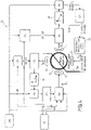
- the flux valve current sensor according to the invention 10 is used here to measure a current to be measured Im which flows on a conductor 11.
- the flux valve current sensor 10 includes a transformer comprising a magnetic core 12 as well as four windings wound around the magnetic core 12.
- the magnetic core 12 extends around the conductor 11.
- the four coils comprise an excitation coil 13, a measurement coil 14, a servo coil 15 and a demagnetization coil 16.
- the measurement coil 14 and the servo coil 15 are here each made up of a winding double.
- the excitation winding 13 is used to excite the magnetic core 12.
- the flux valve current sensor 10 further comprises a low frequency generator 18, a high frequency generator 19 and an excitation module 20 which is connected to the excitation winding 13.
- the low frequency generator 18 transmits a signal C to the two demodulators 42, 43, 34 and 35.
- the excitation module 20 comprises a plurality of functional blocks, among which a first amplifier block 21 with variable gain, a second amplifier block 22 with variable gain, a summing block 23, a gain block 24.
- the first amplifier block 21 receives the signal 1H at the frequency f0
- the second amplifier block 22 receives the signal 3H at the frequency 3.f0
- the gain block 24 receives a gain setpoint Cg.
- the adder block 23 adds the outputs of the first amplifier block 21 and of the second amplifier block 22.
- the excitation module 20 thus makes it possible to generate an excitation voltage Ve from a first voltage V1 of frequency f0 and from a second voltage V2 of frequency 3.f0.
- the measurement winding 14 is used to measure the current Im.
- the flux valve current sensor 10 comprises a synchronous measurement demodulator 32, a first low-pass filter 33 and a first unity gain block 34, which are connected in series with the measurement winding 14.
- the first gain block unit 34 produces a gain selectively equal to 1 or -1.
- the first unity gain block 34 receives a chopping signal C from the low frequency generator 18.
- the synchronous measurement demodulator 32 is connected to a first selection block 35.
- the first selection block 35 receives from the low frequency generator 18 a signal of chopping C and from the high frequency generator 19 a signal 2H of frequency 2.f0.
- the first selection block 35 produces a demodulation signal of frequency 2.f0 denoted respectively 2H- or 2H depending on whether it is in phase or in phase inversion with the signal 2H at the frequency 2.f0.
- the synchronous measurement demodulator 32 multiplies by the demodulation signal 2H-/2H an induced measurement current Iim flowing in the measurement winding 14 and induced by the current Im to be measured.
- a first integral proportional corrector 37 connected to the first unity gain block 34, produces an image voltage Vi of the current Im to be measured.
- the synchronous measurement demodulator 32 comprises an analog switch using fast switches 38 of the MOS type.
- the first low-pass filter 33 is a passive filter.
- the analog switch is clocked by the 2H-/2H demodulation signal in phase or in phase inversion.
- the voltage Vs at the output of the first low-pass filter 33 is an image voltage of the harmonic component of order 2 of the excitation voltage Ve.
- the saturation of the magnetic core 12 causes an asymmetry of the induced measurement current Iim, said induced measurement current Iim being constituted by the sum of a component of frequency f0 in sin( ⁇ 0t), corresponding to the fundamental, and a component of frequency 2.f0 in cos(2 ⁇ 0t), corresponding to the harmonic component of order 2.
- the mean component of the demodulated signal Sd is non-zero and positive. By taking the opposite of the saturation, the mean component of the demodulated signal Sd becomes negative.
- the flux valve current sensor 10 includes a synchronous servo demodulator 40, a second low pass filter 41 and a second unity gain block 42, which are connected in series with the servo coil 15.
- the second block of unity gain 42 produces a gain selectively equal to 1 or -1.
- the second unity gain block 42 receives a continuous signal C from the low frequency generator 18.
- the synchronous servo demodulator 40 is connected to a second selection block 43.
- the second selection block 43 receives from the low frequency generator 18 a chopping C and from the high frequency generator a signal 3H of frequency 3.f0.
- the second selection block 43 produces a 3H-/3H demodulation signal of frequency 3.f0 in phase or in phase inversion.
- the synchronous servo demodulator 40 multiplies the induced servo current Iia by the demodulation signal 3H-/3H.
- a second integral proportional corrector 44 is connected between the second unity gain block 42 and the excitation module 20. The excitation voltage Ve is thus slaved so as to cancel the frequency component 3.f0 of the induced servo current IIa.
- the synchronous servo demodulator 40 is similar to the synchronous measurement demodulator 32, visible on the figure 6 , except that the analog switch is clocked by the 3H-/3H demodulation signal in phase or in phase inversion.
- the demagnetization coil 16 for its part, is connected to the output of the first integral proportional corrector 37 via a voltage-to-current converter 45.
- a demagnetization current Id flows in the demagnetization coil 16 to demagnetize the magnetic core 12.
- the image voltage Vi of the current to be measured Im, at the output of the first integral proportional corrector 37, is applied to the input of the voltage-to-current converter 45.
- the voltage-to-current converter 45 produces the demagnetization current Id from the image voltage Vi of the current to be measured Im.
- the current in output of the first unity gain block 34 forms a current setpoint applied to the input of the first proportional corrector 37.
- the demagnetization current Id is thus slaved from the image voltage Vi of the current to be measured Im so as to compensate for the magnetic flux produced by the current to be measured Im.
- the amplitude of the first voltage V1 and the amplitude of the second voltage V2 are adjusted to obtain an excitation voltage Ve whose frequency component 3.f0 (or harmonic component of order 3) is in phase with the f0 (or fundamental) frequency component.
- the third order harmonic component of the induced servo current Iia flowing in the servo coil 15, obtained after synchronous demodulation via the synchronous servo demodulator 40, is positive.
- the harmonic component of order 3 is attenuated more strongly than the fundamental and the harmonic component of order 3 after synchronous demodulation becomes negative, because the harmonic of order 3 passes in phase opposition with the fundamental.
- the ratio of the amplitude of the harmonic component of order 1 and of the amplitude of the harmonic component of order 3 of the induced servo current Iia evolves until cancellation of the harmonic component of order 3, then until phase inversion of the harmonic component of order 3.
- the operating point corresponding to the cancellation of the harmonic component d order 3 of the induced servo current Iia is therefore an optimal operating point of the current sensor flow valve 10. This optimal operating point corresponds to elbow 9 of the transfer function curve of the figure 1 .
- the enslavement of the excitation voltage Ve therefore consists in controlling the excitation voltage Ve, before the latter is applied to the terminals of the excitation winding 13, to cancel the harmonic component of order 3 of the induced current control Iia.
- the flux valve current sensor 10 thus operates permanently at the optimum operating point. In this way, a maximum gain of the asymmetries introduced by the current Im to be measured and detectable on the induced measurement current Iim is obtained. It is noted that this control by synchronous demodulation of the harmonic component of order 3 is not very sensitive to external electromagnetic disturbances, because all the signals of a frequency different from the frequency 3.f0 generate intermodulation products whose components are filtered by the first low-pass filter 33 connected to the output of synchronous measurement demodulator 32. It should also be noted that this servo-control does not need to be very fast, because the variations originating from external parameters (temperature, aging) are relatively slow.
- the first voltage V1 and the second voltage V2 are here both square-wave voltages. Rectangular voltages are indeed simple to generate, and present significant odd harmonic components.
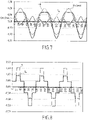
- the triangular signal 51 therefore comprises a negative 3rd order harmonic component.
- the 3rd order harmonic component of the sum between, on the one hand, the spectral decomposition of the first voltage V1 and, on the other hand, the second spectral decomposition of the second voltage V2 is equal to: 4 / ⁇ . E 1 / 3 . sin 3 ⁇ 0 you + E 2 . sin ( 3 ⁇ 0 you .
- the enslavement of the excitation voltage Ve consists in enslaving the amplitude of the second voltage V2. We therefore play on the amplitude of the second voltage V2 to control the excitation voltage Ve so as to cancel the frequency component 3.f0 of the induced servo current Iia.
- the excitation voltage control Ve sought must therefore, before saturation of the magnetic core 12, include a level of relative excitation by the harmonic component of order 3 giving a slightly negative resultant after demodulation by the synchronous servo-control demodulator 40 for to be able, during saturation, to go through 0 then to become negative. It is this particular point that must be adjusted in order to find the best transfer function gain compromise, which corresponds to the optimum operating point and to the bend 9 of the transfer function visible on the figure 1 .
- the signal 2H of frequency 2.f0 and the signal 3H of frequency 3.f0 are periodically inverted in phase, here at a frequency of 10 kHz.
- the offsets in phase opposition are averaged by the first proportional integral corrector 37 and by the second proportional integral corrector 44, and therefore cancelled.
- This phase inversion function at 10kHz makes it possible to compensate for imbalances in the measurement and servo channels, which result from imperfections in the analog components used. This improves the precision of the adjustment of the flow valve sensor 10 to the optimum operating point, and therefore the overall precision of the flow valve sensor 10 itself.
- a first amplifier 53 mounted in buffer two first output resistors 54 of 15 ⁇ each, a first adjustment resistor 55, a second amplifier 56 mounted in buffer, two second output resistors 57 of 15 ⁇ each and a second adjustment resistor 58.
- the value 2.78 is less than 3, and therefore the level of the 3rd order harmonic component of the excitation voltage Ve is greater than that of a square signal, which corresponds to a negative demodulated signal.
- the harmonic component of the voltage 60 at the output of the synchronous servo-control demodulator 40 is canceled for an excitation voltage close to 3V and becomes positive beyond that.
- the zero crossing therefore corresponds to the optimum operating point of the flux valve current sensor 10.
- the transfer function of the flux valve current sensor according to the invention 10 remains in the elbow 9 of the figure 1 .
- the flux valve current sensor 10 has a number of advantages over existing flux valve current sensors.
- synchronous demodulators makes it possible to operate at high frequency, which allows a high bandwidth of the current to be measured Im while maintaining very good immunity to external electromagnetic disturbances.
- the sensitivity of the current sensor with flux valve 10 is constant in the temperature range.
- the accuracy of the flux valve current sensor 10 is therefore good over a wide temperature range.
- the flux valve current sensor 10 is insensitive to manufacturing drifts of certain characteristics of the magnetic core 12.
- the magnetic permeability characteristics of conventional magnetic cores which are not intended to be used in their saturation zone, are very disparate.
- the precise control of the operating point makes it possible to correct these dispersions. It is therefore possible to use standard magnetic cores, which reduces the industrial manufacturing constraints of the magnetic core, and therefore the cost of the current sensor with flux valve 10. It is thus possible to use, for example, a ferrite magnetic core conventionally used in power converters and for certain functions in radioelectricity.
- the flux valve current sensor 10 has an architecture that can be transposed to digital solutions to improve the reproducibility and therefore the manufacture of the flux valve current sensor 10.
- the excitation voltage Ve can be produced by a fast analog-to-digital converter.
- the synchronous measuring 32 and servo 40 demodulators can be implemented on a digital component (for example, on an FPGA). Demagnetization can also occur done via a digital-to-analog converter.
- the second magnetic core would receive the same excitation as the measurement circuit, but in phase opposition, to cancel the flux directly at the level of the conductor on which the current to be measured flows.
Landscapes
- Physics & Mathematics (AREA)
- General Physics & Mathematics (AREA)
- Engineering & Computer Science (AREA)
- Power Engineering (AREA)
- Nonlinear Science (AREA)
- Mathematical Physics (AREA)
- Condensed Matter Physics & Semiconductors (AREA)
- Measuring Magnetic Variables (AREA)
- Measuring Volume Flow (AREA)
- Measuring Instrument Details And Bridges, And Automatic Balancing Devices (AREA)
Claims (6)
- Fluxgate-Stromsensor, umfassend einen Magnetkern (12), der sich um einen Leiter (11) herum erstreckt, auf dem ein zu messender Strom (Im) fließt, eine Erregerwicklung (13), ein Erregermodul (20), das mit der Erregerwicklung verbunden und dazu bestimmt ist, eine Erregerspannung (Ve) zu erzeugen, die eine Frequenzkomponente f0 an den Klemmen der Erregerwicklung umfasst, eine Messwicklung (14), in der ein induzierter Messstrom (Iim) fließt, ein Mess-Synchrondemodulator (32), der mit der Messwicklung verbunden und dazu bestimmt ist, den induzierten Messstrom mit einem Demodulationssignal der Frequenz 2.f0 zu multiplizieren, um ein Spannungsbild des zu messenden Stroms zu erhalten, dadurch gekennzeichnet, dass die Erregerspannung (Ve) aus einer ersten Spannung (V1) der Frequenz f0 und einer zweiten Spannung (V2) der Frequenz 3.f0 erhalten wird, dass der Fluxgate-Stromsensor ferner eine Regelwicklung (15) umfasst, die von der Erregerwicklung getrennt ist und in der ein induzierter Regelstrom fließt, und einen Regel-Synchrondemodulator (40), der mit der Regelwicklung verbunden und dazu bestimmt ist, den induzierten Regelstrom mit einem Demodulationssignal der Frequenz 3.f0 zu multiplizieren, und dass der Regel-Synchrondemodulator (40) mit dem Erregermodul verbunden ist, um die Erregerspannung derart zu regeln, dass eine Frequenzkomponente 3.f0 des induzierten Regelstroms gelöscht wird.
- Fluxgate-Stromsensor nach Anspruch 1, bei dem die erste Spannung (V1) und die zweite Spannung (V2) Rechteckspannungen sind.
- Fluxgate-Stromsensor nach Anspruch 1, bei dem die Erregerspannung (Ve) eine allgemeine dreieckige Form aufweist.
- Fluxgate-Stromsensor nach Anspruch 1, bei dem die Regelung der Erregerspannung darin besteht, die Amplitude der zweiten Spannung (V2) zu regeln.
- Fluxgate-Stromsensor nach Anspruch 1, bei dem das Demodulationssignal der Frequenz 2.f0 ein Signal mit cos2ω0t ist, wobei ω0=2πf0 ist.
- Fluxgate-Stromsensor nach Anspruch 1, ferner umfassend eine Entmagnetisierungswicklung (16), in der ein Entmagnetisierungsstrom (Id) fließt, der ausgehend von dem Spannungsbild des zu messenden Stroms geregelt wird, um einen von dem zu messenden Strom (Im) erzeugten Magnetfluss zu kompensieren.
Applications Claiming Priority (2)
| Application Number | Priority Date | Filing Date | Title |
|---|---|---|---|
| FR1662794A FR3060757B1 (fr) | 2016-12-19 | 2016-12-19 | Capteur de courant a vanne de flux |
| PCT/EP2017/083671 WO2018115032A1 (fr) | 2016-12-19 | 2017-12-19 | Capteur de courant a vanne de flux |
Publications (2)
| Publication Number | Publication Date |
|---|---|
| EP3555642A1 EP3555642A1 (de) | 2019-10-23 |
| EP3555642B1 true EP3555642B1 (de) | 2022-11-23 |
Family
ID=57965997
Family Applications (1)
| Application Number | Title | Priority Date | Filing Date |
|---|---|---|---|
| EP17821617.2A Active EP3555642B1 (de) | 2016-12-19 | 2017-12-19 | Stromsensor mit fluxgate |
Country Status (6)
| Country | Link |
|---|---|
| US (1) | US10884028B2 (de) |
| EP (1) | EP3555642B1 (de) |
| CN (1) | CN110088636B (de) |
| FR (1) | FR3060757B1 (de) |
| RU (1) | RU2718758C1 (de) |
| WO (1) | WO2018115032A1 (de) |
Families Citing this family (8)
| Publication number | Priority date | Publication date | Assignee | Title |
|---|---|---|---|---|
| FR3083321B1 (fr) * | 2018-06-27 | 2021-03-05 | Safran Electronics & Defense | Capteur de courant a vanne de flux |
| DE102018130690B3 (de) * | 2018-12-03 | 2020-03-26 | Bender Gmbh & Co. Kg | Magnetfeld-Messvorrichtung und Verfahren zur Erfassung eines Lokalisierungsstroms in einem verzweigten Wechselstrom-Stromversorgungssystem |
| US11047928B2 (en) * | 2019-07-15 | 2021-06-29 | Allegro Microsystems, Llc | Methods and apparatus for frequency effect compensation in magnetic field current sensors |
| EP3771915A1 (de) * | 2019-07-31 | 2021-02-03 | LEM International SA | Verfahren zur rauschverminderung in einem fluxgate-stromwandler |
| FR3105428B1 (fr) * | 2019-12-20 | 2021-11-26 | Safran Electronics & Defense | Capteur accélérométrique pendulaire à détection capacitive conditionnelle |
| FR3116608B1 (fr) * | 2020-11-26 | 2022-12-23 | Chauvin Arnoux | Dispositif de mesure de courant électrique sans contact à noyau magnétique flexible |
| CN114706024A (zh) * | 2022-04-01 | 2022-07-05 | 哈尔滨工程大学 | 一种适用于mems磁通门传感器的混合式锁相放大电路及其控制方法 |
| CN119667567B (zh) * | 2024-11-14 | 2025-10-10 | 南方电网传感科技(广东)有限公司 | 磁通门电路 |
Citations (3)
| Publication number | Priority date | Publication date | Assignee | Title |
|---|---|---|---|---|
| EP0137347A1 (de) * | 1983-09-15 | 1985-04-17 | Danfysik A/S | Strommessdetektorschaltung |
| WO2014047644A2 (en) * | 2012-09-24 | 2014-03-27 | Shane Clamme | Measuring dc current with a current transformer |
| WO2016016038A1 (en) * | 2014-07-30 | 2016-02-04 | Lem Intellectual Property Sa | Current transducer with fluxgate detector |
Family Cites Families (14)
| Publication number | Priority date | Publication date | Assignee | Title |
|---|---|---|---|---|
| US3435337A (en) * | 1964-12-11 | 1969-03-25 | Trw Inc | Superconductive fluxgate magnetometer |
| WO1991013366A1 (fr) * | 1990-02-28 | 1991-09-05 | Nippon Kokan Kk | Procede et appareil de detection magnetique |
| JPH11281678A (ja) * | 1998-03-30 | 1999-10-15 | Shimadzu Corp | 電流センサ |
| EP1746430A1 (de) * | 2005-07-22 | 2007-01-24 | Liaisons Electroniques-Mecaniques Lem S.A. | Orthogonale Fluxgate-Magnetfeldsensor |
| FR2891917B1 (fr) * | 2005-10-07 | 2008-01-11 | Billanco | Capteurs de champ magnetique et de courant, procede de commande et noyau magnetique pour ces capteurs |
| DE102007032300A1 (de) * | 2007-07-11 | 2009-01-22 | Siemens Ag | Stromsensor zur Gleich- oder Wechselstrommessung |
| FR2942880A1 (fr) * | 2009-03-04 | 2010-09-10 | Commissariat Energie Atomique | Capteurs de courant et procede de fabrication de ces capteurs. |
| EP2587268A1 (de) * | 2011-10-26 | 2013-05-01 | LEM Intellectual Property SA | Elektrischer Stromwandler |
| CN202330528U (zh) * | 2011-11-28 | 2012-07-11 | 河北工业大学 | 双轴磁通门电流传感器 |
| EP2682762A1 (de) * | 2012-07-06 | 2014-01-08 | Senis AG | Stromwandler zum Messen von Strom, magnetischer Wandler und Stromleckagenerkennungssystem und -verfahren |
| RU2555200C2 (ru) * | 2013-08-06 | 2015-07-10 | Феликс Матвеевич Медников | Способ температурной компенсации индуктивного датчика положения и устройство для его реализации |
| CA2868663C (en) * | 2013-10-21 | 2016-11-08 | Tomasz Barczyk | Methods and systems relating to ac current measurements |
| CN104374982A (zh) * | 2014-07-25 | 2015-02-25 | 中国计量科学研究院 | 一种非接触式直流电流测量电路及方法 |
| US9523719B2 (en) * | 2014-10-10 | 2016-12-20 | Bose Corporation | Current sensor |
-
2016
- 2016-12-19 FR FR1662794A patent/FR3060757B1/fr active Active
-
2017
- 2017-12-19 RU RU2019122657A patent/RU2718758C1/ru active
- 2017-12-19 US US16/470,480 patent/US10884028B2/en active Active
- 2017-12-19 CN CN201780078327.2A patent/CN110088636B/zh active Active
- 2017-12-19 WO PCT/EP2017/083671 patent/WO2018115032A1/fr not_active Ceased
- 2017-12-19 EP EP17821617.2A patent/EP3555642B1/de active Active
Patent Citations (3)
| Publication number | Priority date | Publication date | Assignee | Title |
|---|---|---|---|---|
| EP0137347A1 (de) * | 1983-09-15 | 1985-04-17 | Danfysik A/S | Strommessdetektorschaltung |
| WO2014047644A2 (en) * | 2012-09-24 | 2014-03-27 | Shane Clamme | Measuring dc current with a current transformer |
| WO2016016038A1 (en) * | 2014-07-30 | 2016-02-04 | Lem Intellectual Property Sa | Current transducer with fluxgate detector |
Also Published As
| Publication number | Publication date |
|---|---|
| US10884028B2 (en) | 2021-01-05 |
| FR3060757B1 (fr) | 2020-11-06 |
| RU2718758C1 (ru) | 2020-04-14 |
| US20190317135A1 (en) | 2019-10-17 |
| EP3555642A1 (de) | 2019-10-23 |
| CN110088636B (zh) | 2021-06-22 |
| FR3060757A1 (fr) | 2018-06-22 |
| CN110088636A (zh) | 2019-08-02 |
| WO2018115032A1 (fr) | 2018-06-28 |
Similar Documents
| Publication | Publication Date | Title |
|---|---|---|
| WO2018115032A1 (fr) | Capteur de courant a vanne de flux | |
| CA2707102C (fr) | Capteur de courant perfectionne | |
| EP0499589B1 (de) | Vorrichtung zum Messen von Strömen | |
| EP3815117B1 (de) | Messwandler mit einer leiterplatte | |
| EP2089724B1 (de) | Messgerät für elektrische energie mit mindestens einem induktiven stromsensor und entsprechender sensor | |
| EP3814782A1 (de) | Stromsensor mit flux-gate | |
| EP3814783A1 (de) | Leiterplatte mit einer stromteilerbrücke | |
| EP1217707B1 (de) | Verfahren zur Bestimmung eines Primärstroms für Stromwandler mit Sättigungskorrekturmitteln | |
| FR2496896A1 (fr) | Dispositif de mesure de puissance ou d'energie electriques | |
| WO2004042410A1 (fr) | Dispositif de mesure de l’intensite d’un courant electrique | |
| EP2830215B1 (de) | Ladungsvorverstärker | |
| EP4260073B1 (de) | Stromfühler mit zwei in eins spule | |
| EP1417505B1 (de) | Magnetometer mit strukturasymmetriekorrektur | |
| CH703739A2 (fr) | Circuit de commande d'un moteur électrique avec un asservissement du courant d'alimentation. | |
| EP0738894B1 (de) | Stromfühler mit Magnetfelddetektor | |
| FR2752059A1 (fr) | Dispositif de mesure d'un courant circulant dans un conducteur | |
| EP0609113B1 (de) | Vorrichtung zur Messung einer elektrischen Gleichstromgrösse, beispielsweise einer Spannung | |
| FR2744529A1 (fr) | Procede et dispositif de mesure d'un courant electrique continu de faible valeur | |
| EP1020728B1 (de) | Anordnung zum messen eines Stromes in einer Leitung | |
| FR3022032A1 (fr) | Regulateur auto-oscillant sur harmonique de l'excitation |
Legal Events
| Date | Code | Title | Description |
|---|---|---|---|
| STAA | Information on the status of an ep patent application or granted ep patent |
Free format text: STATUS: UNKNOWN |
|
| STAA | Information on the status of an ep patent application or granted ep patent |
Free format text: STATUS: THE INTERNATIONAL PUBLICATION HAS BEEN MADE |
|
| PUAI | Public reference made under article 153(3) epc to a published international application that has entered the european phase |
Free format text: ORIGINAL CODE: 0009012 |
|
| STAA | Information on the status of an ep patent application or granted ep patent |
Free format text: STATUS: REQUEST FOR EXAMINATION WAS MADE |
|
| 17P | Request for examination filed |
Effective date: 20190605 |
|
| AK | Designated contracting states |
Kind code of ref document: A1 Designated state(s): AL AT BE BG CH CY CZ DE DK EE ES FI FR GB GR HR HU IE IS IT LI LT LU LV MC MK MT NL NO PL PT RO RS SE SI SK SM TR |
|
| AX | Request for extension of the european patent |
Extension state: BA ME |
|
| DAV | Request for validation of the european patent (deleted) | ||
| DAX | Request for extension of the european patent (deleted) | ||
| GRAP | Despatch of communication of intention to grant a patent |
Free format text: ORIGINAL CODE: EPIDOSNIGR1 |
|
| STAA | Information on the status of an ep patent application or granted ep patent |
Free format text: STATUS: GRANT OF PATENT IS INTENDED |
|
| INTG | Intention to grant announced |
Effective date: 20220201 |
|
| GRAJ | Information related to disapproval of communication of intention to grant by the applicant or resumption of examination proceedings by the epo deleted |
Free format text: ORIGINAL CODE: EPIDOSDIGR1 |
|
| STAA | Information on the status of an ep patent application or granted ep patent |
Free format text: STATUS: REQUEST FOR EXAMINATION WAS MADE |
|
| GRAP | Despatch of communication of intention to grant a patent |
Free format text: ORIGINAL CODE: EPIDOSNIGR1 |
|
| STAA | Information on the status of an ep patent application or granted ep patent |
Free format text: STATUS: GRANT OF PATENT IS INTENDED |
|
| INTC | Intention to grant announced (deleted) | ||
| INTG | Intention to grant announced |
Effective date: 20220617 |
|
| GRAS | Grant fee paid |
Free format text: ORIGINAL CODE: EPIDOSNIGR3 |
|
| GRAA | (expected) grant |
Free format text: ORIGINAL CODE: 0009210 |
|
| STAA | Information on the status of an ep patent application or granted ep patent |
Free format text: STATUS: THE PATENT HAS BEEN GRANTED |
|
| AK | Designated contracting states |
Kind code of ref document: B1 Designated state(s): AL AT BE BG CH CY CZ DE DK EE ES FI FR GB GR HR HU IE IS IT LI LT LU LV MC MK MT NL NO PL PT RO RS SE SI SK SM TR |
|
| REG | Reference to a national code |
Ref country code: GB Ref legal event code: FG4D Free format text: NOT ENGLISH |
|
| RIN1 | Information on inventor provided before grant (corrected) |
Inventor name: GUILLOT, FRANCOIS |
|
| REG | Reference to a national code |
Ref country code: CH Ref legal event code: EP |
|
| REG | Reference to a national code |
Ref country code: DE Ref legal event code: R096 Ref document number: 602017063981 Country of ref document: DE |
|
| REG | Reference to a national code |
Ref country code: AT Ref legal event code: REF Ref document number: 1533448 Country of ref document: AT Kind code of ref document: T Effective date: 20221215 |
|
| REG | Reference to a national code |
Ref country code: IE Ref legal event code: FG4D Free format text: LANGUAGE OF EP DOCUMENT: FRENCH |
|
| REG | Reference to a national code |
Ref country code: LT Ref legal event code: MG9D |
|
| REG | Reference to a national code |
Ref country code: NL Ref legal event code: MP Effective date: 20221123 |
|
| REG | Reference to a national code |
Ref country code: AT Ref legal event code: MK05 Ref document number: 1533448 Country of ref document: AT Kind code of ref document: T Effective date: 20221123 |
|
| PG25 | Lapsed in a contracting state [announced via postgrant information from national office to epo] |
Ref country code: SE Free format text: LAPSE BECAUSE OF FAILURE TO SUBMIT A TRANSLATION OF THE DESCRIPTION OR TO PAY THE FEE WITHIN THE PRESCRIBED TIME-LIMIT Effective date: 20221123 Ref country code: PT Free format text: LAPSE BECAUSE OF FAILURE TO SUBMIT A TRANSLATION OF THE DESCRIPTION OR TO PAY THE FEE WITHIN THE PRESCRIBED TIME-LIMIT Effective date: 20230323 Ref country code: NO Free format text: LAPSE BECAUSE OF FAILURE TO SUBMIT A TRANSLATION OF THE DESCRIPTION OR TO PAY THE FEE WITHIN THE PRESCRIBED TIME-LIMIT Effective date: 20230223 Ref country code: LT Free format text: LAPSE BECAUSE OF FAILURE TO SUBMIT A TRANSLATION OF THE DESCRIPTION OR TO PAY THE FEE WITHIN THE PRESCRIBED TIME-LIMIT Effective date: 20221123 Ref country code: FI Free format text: LAPSE BECAUSE OF FAILURE TO SUBMIT A TRANSLATION OF THE DESCRIPTION OR TO PAY THE FEE WITHIN THE PRESCRIBED TIME-LIMIT Effective date: 20221123 Ref country code: ES Free format text: LAPSE BECAUSE OF FAILURE TO SUBMIT A TRANSLATION OF THE DESCRIPTION OR TO PAY THE FEE WITHIN THE PRESCRIBED TIME-LIMIT Effective date: 20221123 Ref country code: AT Free format text: LAPSE BECAUSE OF FAILURE TO SUBMIT A TRANSLATION OF THE DESCRIPTION OR TO PAY THE FEE WITHIN THE PRESCRIBED TIME-LIMIT Effective date: 20221123 |
|
| PG25 | Lapsed in a contracting state [announced via postgrant information from national office to epo] |
Ref country code: RS Free format text: LAPSE BECAUSE OF FAILURE TO SUBMIT A TRANSLATION OF THE DESCRIPTION OR TO PAY THE FEE WITHIN THE PRESCRIBED TIME-LIMIT Effective date: 20221123 Ref country code: PL Free format text: LAPSE BECAUSE OF FAILURE TO SUBMIT A TRANSLATION OF THE DESCRIPTION OR TO PAY THE FEE WITHIN THE PRESCRIBED TIME-LIMIT Effective date: 20221123 Ref country code: LV Free format text: LAPSE BECAUSE OF FAILURE TO SUBMIT A TRANSLATION OF THE DESCRIPTION OR TO PAY THE FEE WITHIN THE PRESCRIBED TIME-LIMIT Effective date: 20221123 Ref country code: IS Free format text: LAPSE BECAUSE OF FAILURE TO SUBMIT A TRANSLATION OF THE DESCRIPTION OR TO PAY THE FEE WITHIN THE PRESCRIBED TIME-LIMIT Effective date: 20230323 Ref country code: HR Free format text: LAPSE BECAUSE OF FAILURE TO SUBMIT A TRANSLATION OF THE DESCRIPTION OR TO PAY THE FEE WITHIN THE PRESCRIBED TIME-LIMIT Effective date: 20221123 Ref country code: GR Free format text: LAPSE BECAUSE OF FAILURE TO SUBMIT A TRANSLATION OF THE DESCRIPTION OR TO PAY THE FEE WITHIN THE PRESCRIBED TIME-LIMIT Effective date: 20230224 |
|
| PG25 | Lapsed in a contracting state [announced via postgrant information from national office to epo] |
Ref country code: NL Free format text: LAPSE BECAUSE OF FAILURE TO SUBMIT A TRANSLATION OF THE DESCRIPTION OR TO PAY THE FEE WITHIN THE PRESCRIBED TIME-LIMIT Effective date: 20221123 |
|
| PG25 | Lapsed in a contracting state [announced via postgrant information from national office to epo] |
Ref country code: SM Free format text: LAPSE BECAUSE OF FAILURE TO SUBMIT A TRANSLATION OF THE DESCRIPTION OR TO PAY THE FEE WITHIN THE PRESCRIBED TIME-LIMIT Effective date: 20221123 Ref country code: RO Free format text: LAPSE BECAUSE OF FAILURE TO SUBMIT A TRANSLATION OF THE DESCRIPTION OR TO PAY THE FEE WITHIN THE PRESCRIBED TIME-LIMIT Effective date: 20221123 Ref country code: EE Free format text: LAPSE BECAUSE OF FAILURE TO SUBMIT A TRANSLATION OF THE DESCRIPTION OR TO PAY THE FEE WITHIN THE PRESCRIBED TIME-LIMIT Effective date: 20221123 Ref country code: DK Free format text: LAPSE BECAUSE OF FAILURE TO SUBMIT A TRANSLATION OF THE DESCRIPTION OR TO PAY THE FEE WITHIN THE PRESCRIBED TIME-LIMIT Effective date: 20221123 Ref country code: CZ Free format text: LAPSE BECAUSE OF FAILURE TO SUBMIT A TRANSLATION OF THE DESCRIPTION OR TO PAY THE FEE WITHIN THE PRESCRIBED TIME-LIMIT Effective date: 20221123 |
|
| REG | Reference to a national code |
Ref country code: CH Ref legal event code: PL |
|
| REG | Reference to a national code |
Ref country code: DE Ref legal event code: R097 Ref document number: 602017063981 Country of ref document: DE Ref country code: BE Ref legal event code: MM Effective date: 20221231 |
|
| PG25 | Lapsed in a contracting state [announced via postgrant information from national office to epo] |
Ref country code: SK Free format text: LAPSE BECAUSE OF FAILURE TO SUBMIT A TRANSLATION OF THE DESCRIPTION OR TO PAY THE FEE WITHIN THE PRESCRIBED TIME-LIMIT Effective date: 20221123 Ref country code: LU Free format text: LAPSE BECAUSE OF NON-PAYMENT OF DUE FEES Effective date: 20221219 Ref country code: AL Free format text: LAPSE BECAUSE OF FAILURE TO SUBMIT A TRANSLATION OF THE DESCRIPTION OR TO PAY THE FEE WITHIN THE PRESCRIBED TIME-LIMIT Effective date: 20221123 |
|
| PLBE | No opposition filed within time limit |
Free format text: ORIGINAL CODE: 0009261 |
|
| STAA | Information on the status of an ep patent application or granted ep patent |
Free format text: STATUS: NO OPPOSITION FILED WITHIN TIME LIMIT |
|
| PG25 | Lapsed in a contracting state [announced via postgrant information from national office to epo] |
Ref country code: LI Free format text: LAPSE BECAUSE OF NON-PAYMENT OF DUE FEES Effective date: 20221231 Ref country code: IE Free format text: LAPSE BECAUSE OF NON-PAYMENT OF DUE FEES Effective date: 20221219 Ref country code: CH Free format text: LAPSE BECAUSE OF NON-PAYMENT OF DUE FEES Effective date: 20221231 |
|
| 26N | No opposition filed |
Effective date: 20230824 |
|
| PG25 | Lapsed in a contracting state [announced via postgrant information from national office to epo] |
Ref country code: SI Free format text: LAPSE BECAUSE OF FAILURE TO SUBMIT A TRANSLATION OF THE DESCRIPTION OR TO PAY THE FEE WITHIN THE PRESCRIBED TIME-LIMIT Effective date: 20221123 Ref country code: BE Free format text: LAPSE BECAUSE OF NON-PAYMENT OF DUE FEES Effective date: 20221231 |
|
| PG25 | Lapsed in a contracting state [announced via postgrant information from national office to epo] |
Ref country code: HU Free format text: LAPSE BECAUSE OF FAILURE TO SUBMIT A TRANSLATION OF THE DESCRIPTION OR TO PAY THE FEE WITHIN THE PRESCRIBED TIME-LIMIT; INVALID AB INITIO Effective date: 20171219 |
|
| PG25 | Lapsed in a contracting state [announced via postgrant information from national office to epo] |
Ref country code: CY Free format text: LAPSE BECAUSE OF FAILURE TO SUBMIT A TRANSLATION OF THE DESCRIPTION OR TO PAY THE FEE WITHIN THE PRESCRIBED TIME-LIMIT Effective date: 20221123 |
|
| PG25 | Lapsed in a contracting state [announced via postgrant information from national office to epo] |
Ref country code: MK Free format text: LAPSE BECAUSE OF FAILURE TO SUBMIT A TRANSLATION OF THE DESCRIPTION OR TO PAY THE FEE WITHIN THE PRESCRIBED TIME-LIMIT Effective date: 20221123 Ref country code: IT Free format text: LAPSE BECAUSE OF FAILURE TO SUBMIT A TRANSLATION OF THE DESCRIPTION OR TO PAY THE FEE WITHIN THE PRESCRIBED TIME-LIMIT Effective date: 20221123 |
|
| PG25 | Lapsed in a contracting state [announced via postgrant information from national office to epo] |
Ref country code: MC Free format text: LAPSE BECAUSE OF FAILURE TO SUBMIT A TRANSLATION OF THE DESCRIPTION OR TO PAY THE FEE WITHIN THE PRESCRIBED TIME-LIMIT Effective date: 20221123 |
|
| PG25 | Lapsed in a contracting state [announced via postgrant information from national office to epo] |
Ref country code: MC Free format text: LAPSE BECAUSE OF FAILURE TO SUBMIT A TRANSLATION OF THE DESCRIPTION OR TO PAY THE FEE WITHIN THE PRESCRIBED TIME-LIMIT Effective date: 20221123 |
|
| PG25 | Lapsed in a contracting state [announced via postgrant information from national office to epo] |
Ref country code: BG Free format text: LAPSE BECAUSE OF FAILURE TO SUBMIT A TRANSLATION OF THE DESCRIPTION OR TO PAY THE FEE WITHIN THE PRESCRIBED TIME-LIMIT Effective date: 20221123 |
|
| PG25 | Lapsed in a contracting state [announced via postgrant information from national office to epo] |
Ref country code: MT Free format text: LAPSE BECAUSE OF FAILURE TO SUBMIT A TRANSLATION OF THE DESCRIPTION OR TO PAY THE FEE WITHIN THE PRESCRIBED TIME-LIMIT Effective date: 20221123 |
|
| PG25 | Lapsed in a contracting state [announced via postgrant information from national office to epo] |
Ref country code: TR Free format text: LAPSE BECAUSE OF FAILURE TO SUBMIT A TRANSLATION OF THE DESCRIPTION OR TO PAY THE FEE WITHIN THE PRESCRIBED TIME-LIMIT Effective date: 20221123 |
|
| PGFP | Annual fee paid to national office [announced via postgrant information from national office to epo] |
Ref country code: GB Payment date: 20251229 Year of fee payment: 9 |
|
| PGFP | Annual fee paid to national office [announced via postgrant information from national office to epo] |
Ref country code: FR Payment date: 20251222 Year of fee payment: 9 |
|
| PGFP | Annual fee paid to national office [announced via postgrant information from national office to epo] |
Ref country code: DE Payment date: 20251222 Year of fee payment: 9 |