EP3555707B1 - Uhrwerk mit automatischer montage - Google Patents
Uhrwerk mit automatischer montage Download PDFInfo
- Publication number
- EP3555707B1 EP3555707B1 EP17817192.2A EP17817192A EP3555707B1 EP 3555707 B1 EP3555707 B1 EP 3555707B1 EP 17817192 A EP17817192 A EP 17817192A EP 3555707 B1 EP3555707 B1 EP 3555707B1
- Authority
- EP
- European Patent Office
- Prior art keywords
- timepiece movement
- fixed plate
- time
- mobile chassis
- gear train
- Prior art date
- Legal status (The legal status is an assumption and is not a legal conclusion. Google has not performed a legal analysis and makes no representation as to the accuracy of the status listed.)
- Active
Links
Images




Classifications
-
- G—PHYSICS
- G04—HOROLOGY
- G04B—MECHANICALLY-DRIVEN CLOCKS OR WATCHES; MECHANICAL PARTS OF CLOCKS OR WATCHES IN GENERAL; TIME PIECES USING THE POSITION OF THE SUN, MOON OR STARS
- G04B5/00—Automatic winding up
- G04B5/02—Automatic winding up by self-winding caused by the movement of the watch
- G04B5/10—Automatic winding up by self-winding caused by the movement of the watch by oscillating weights the movement of which is not limited
- G04B5/14—Automatic winding up by self-winding caused by the movement of the watch by oscillating weights the movement of which is not limited acting in both directions
-
- G—PHYSICS
- G04—HOROLOGY
- G04B—MECHANICALLY-DRIVEN CLOCKS OR WATCHES; MECHANICAL PARTS OF CLOCKS OR WATCHES IN GENERAL; TIME PIECES USING THE POSITION OF THE SUN, MOON OR STARS
- G04B5/00—Automatic winding up
- G04B5/002—Automatic winding up by moving of parts of the clockwork which are not primarily for winding up
-
- G—PHYSICS
- G04—HOROLOGY
- G04B—MECHANICALLY-DRIVEN CLOCKS OR WATCHES; MECHANICAL PARTS OF CLOCKS OR WATCHES IN GENERAL; TIME PIECES USING THE POSITION OF THE SUN, MOON OR STARS
- G04B45/00—Time pieces of which the indicating means or cases provoke special effects, e.g. aesthetic effects
- G04B45/02—Time pieces of which the clockwork is visible partly or wholly
-
- G—PHYSICS
- G04—HOROLOGY
- G04B—MECHANICALLY-DRIVEN CLOCKS OR WATCHES; MECHANICAL PARTS OF CLOCKS OR WATCHES IN GENERAL; TIME PIECES USING THE POSITION OF THE SUN, MOON OR STARS
- G04B5/00—Automatic winding up
- G04B5/02—Automatic winding up by self-winding caused by the movement of the watch
- G04B5/16—Construction of the weights
-
- G—PHYSICS
- G04—HOROLOGY
- G04B—MECHANICALLY-DRIVEN CLOCKS OR WATCHES; MECHANICAL PARTS OF CLOCKS OR WATCHES IN GENERAL; TIME PIECES USING THE POSITION OF THE SUN, MOON OR STARS
- G04B5/00—Automatic winding up
- G04B5/02—Automatic winding up by self-winding caused by the movement of the watch
- G04B5/16—Construction of the weights
- G04B5/165—Weights consisting of several parts
Definitions
- the present invention relates to a self-winding watch movement.
- the present invention aims to provide a self-winding horological movement having a structure very different from that of known movements and producing an attractive effect.
- the present invention also provides a watch comprising such a watch movement.
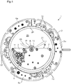
- a watch movement 1 intended to be mounted in a watch case, comprises a fixed plate 2 of annular shape around an imaginary axis A and on which are mounted a setting gear at hour 3, a cog timer 4 and an inertial gear 5 covered by respective bridges 3a, 4a, 5a.
- a semi-circular mobile stage 6 and bridges 7 fixed to the mobile stage 6 constitute a rotating frame around the axis A and surrounded by the fixed stage 2.
- the mobile stage 6 is fixed to a transparent disc 8.
- the movable plate 6 is for example glued directly on the transparent disc 8 or assembled by screwing or the like to a metal deposit formed on the transparent disc 8.
- the transparent disc 8 is itself fixed in the inner ring 9 of a ball bearing , for example by clamping between the ring 9 and an attached part or by screwing, clamping or driving.
- This inner ring 9 carries a set of teeth 9a which meshes with the first mobile 5b of the inertial gear 5.
- the outer ring 10 of the ball bearing is fixed to the fixed plate 2, under the latter, for example by screwing.
- the time measuring mechanism 11 comprises, in a conventional manner per se, a power source 11a of the barrel type, a finishing gear train 11b driven by the barrel 11a and a regulating member 11c comprising an escapement and a sprung balance.
- the automatic winding gear 12 for its part (cf. figure 5 ) meshes by the first of its mobile with a fixed wheel 13 and by the last of its mobile with the ratchet 11d of the barrel 11a, and comprises a reduction gear 12a and an inverter 12b as is known per se.
- the movable frame 6, 7 is unbalanced relative to the axis A, that is to say has an unbalance, and thus constitutes with all the elements that it carries, in particular the time measuring mechanism 11 and the automatic winding gear 12, an oscillating mass M which rotates freely around the axis A under the effect of the movements of the arm of the wearer of the watch.
- the rotations of the oscillating weight M around the axis A actuate the winding gear automatic 12 which rotates the ratchet 11d to wind up the mainspring housed in the barrel 11a.
- the inertial gear train 5 comprises a flywheel 5c to regulate the speed of rotation of the oscillating mass M in order to prevent rebat from occurring in the regulating member 11c under the effect of strong accelerations.
- the flywheel 5c can be of different types, for example a simple rotating mass or a rotating member comprising elastic portions carrying masses which rub against a fixed drum.
- Two rods 14, 15 of axis A driven out or fixed in another way in the mobile plate 6 form a physical axis (cf. figure 3 ).
- a tube 16 free to rotate with respect to the rod 14 and on which is fixed a minute wheel 17.
- a transparent minutes disc 18 located above the oscillating mass M is made integral in rotation. of the tube 16 by a ring 19 fixed, for example driven out, in a central hole of the disc 18 and the interior surface of which has a polygonal section and cooperates with a part of the exterior surface of the tube 16 with a corresponding polygonal section.
- This ring 19 carries a minute indicator hand 20.
- the transparent minutes disc 18 is provided at its periphery with a toothing 21 which meshes with the first mobile 4b of the timer gear 4.
- a transparent hours disc 23 provided with a peripheral toothing 24 which meshes with the last mobile 4c of the timer gear 4.
- the transparent 23 hours disc is located above the oscillating mass M and leaves the said oscillating mass visible.
- the ring 22 is fixed in a central hole of the disc 23 and carries an hour indicator hand 25.
- the teeth 21, 24 can be attached metal teeth, as illustrated, or teeth machined directly in the material of the discs 18, 23.
- the transparent minutes and hours discs 18, 23 are held axially by bridges 32 (visible at figures 1 and 2 ) attached to the fixed plate 2.
- the fixed wheel 13 is mounted around the rod 15 so that the latter can rotate freely relative to the fixed wheel 13.
- a transparent disc 26 fixed by one or more flanges 27 to a ring 2a which is itself fixed, for example. screwed to the fixed plate 2 serves to block the fixed wheel 13 in rotation relative to the fixed plate 2.
- the outer surface of a barrel 13a of the fixed wheel 13 comprises a part with a polygonal section engaged in the hole, with a corresponding polygonal section, of a ring 28 fixed in a central hole of the transparent disc 26.
- the fixed wheel 13 cooperates on one side with a bearing surface 15a of the rod 15 and of the the other side with a bearing 29 secured to the movable frame 6, 7 and which guides the rotation of the barrel 13a.
- the transparent discs 8, 18, 23, 26 are typically made of sapphire, but they can be made of any other suitable transparent material.
- the minute wheel 17, the transparent discs 8, 18, 23, 26, the minute and hour indicator hands 20, 25, the fixed wheel 13 and the rings 9, 10 of the ball bearing are coaxial with the fixed plate 2 and therefore have the axis A as a common axis.
- the outside diameter of each of the transparent discs 8, 18, 23, 26 (not including, where applicable, their toothing) is greater than the minimum inside diameter of the fixed plate 2.
- the movable frame 6, 7 of the oscillating mass M is preferably perforated to make visible all or part of the components of the time measuring mechanism 11 and of the automatic winding gear 12. With its time measuring mechanism 11 and its gear train. automatic winding 12 integrated into the oscillating weight M and rotating with it, the watch movement 1 exerts an attractive and surprising effect on the user.
- the minute and hour indicator hands 20, 25 are independent of the rotation of the oscillating mass M. They turn in fact in the same way as in a traditional watch where the time measuring mechanism is mounted on a fixed plate. This allows direct and easy reading of the time by the wearer.
- a differential 30 is mounted in the frame 6, 7 of the oscillating mass M.
- the differential 30 comprises a first input wheel 30a coaxial and integral with an input shaft 30b.
- the differential 30 further comprises, around the input shaft 30b, a planet carrier 30c, a second input wheel 30d integral with the planet carrier 30c, a satellite drive wheel 30e and an output mobile. 30f.
- the planet carrier 30c, the second input wheel 30d and the output mobile 30f are free to rotate relative to the input shaft 30b.
- the satellite drive wheel 30e is integral in rotation with the input shaft 30b.
- the planet carrier 30c carries planet wheels 30g which each mesh, by a set of teeth, with the satellite drive wheel 30e, and by another set of teeth, with the pinion of the output wheel set 30f.
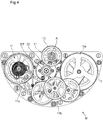
- the wheel of the output mobile 30f meshes with the minute wheel 17 as can be seen in figures 3 and 4 .
- the mobiles forming the satellites 30g can be one, two or three in number as in the existing differentials.
- the first input wheel 30a is connected by a gear train (not shown) to a connecting pinion 31 which itself meshes with the barrel 11a (cf. figure 4 ).
- This first input wheel 30a thus rotates at a speed which is representative of the time measured and which is correct with respect to the oscillating mass M but false with respect to the fixed plate 2.
- the second input wheel 30d is connected by a gear train (not shown) to the fixed wheel 13 and thus rotates at a speed related to the rotation of the oscillating mass M.
- the differential 30 subtracts the second speed from the first to rotate the minute wheel 17 and therefore l 'minute indicator hand 20 at the rate of one revolution per hour with respect to the fixed plate 2.
- the minute wheel 17 rotates the transparent hours disc 23 and therefore the hour indicator hand 25 at the rate of one revolution per 12 hours in relation to the fixed plate 2.
- the time-setting gear 3 is associated with a control rod 3b which can be actuated by the user in a conventional manner.
- One 3c of the wheels of the time-setting train 3 meshes with the toothing 21 of the transparent minute disc 18.
- a rotation of the control rod 3b after the latter has been pulled from a neutral position therefore rotates the transparent 18 minutes disc which, by means of the timer gear 4, rotates the transparent 23 hours disc, thus allowing adjustment of the angular position of the 20, 25 hour and minute indicator hands.
- minutes 17 is mounted in friction around the tube 16 to be integral in rotation with the latter except when setting the time when the friction is overcome by the torque exerted by the user on the control rod 3b, which avoids the risk of breakage in the time measuring mechanism 11.
- the figure 7 shows a variant of the watch movement 1 according to the invention, in which the timer train 4 mounted on the fixed plate 2 is replaced by a timer mobile 33 mounted in the frame 6, 7 of the oscillating mass M.
- the transparent hour disc 23 is omitted, the pinion of the minute wheel set 33 meshes with the minute wheel 17 and the wheel of the minute wheel set 33 meshes with an hour wheel coaxial with the minute wheel 17 and carrying the indicator hand of 25 hours.
Landscapes
- Physics & Mathematics (AREA)
- General Physics & Mathematics (AREA)
- Electromechanical Clocks (AREA)
- Measurement Of Unknown Time Intervals (AREA)
Claims (14)
- Uhrwerk, das umfasst:- eine feste Werkplatte (2),- einen Zeitmessungsmechanismus (11), der eine Energiequelle (11a), ein Räderwerk (11b), das von der Energiequelle (11a) angetrieben wird, und ein Regulierorgan (11c) umfasst, das mit dem Räderwerk (11b) zusammenwirkt,- mindestens einen Zeitanzeiger (20, 25), der von dem Zeitmessungsmechanismus (11) angetrieben wird,- ein Räderwerk (12) zum automatischen Aufziehen, und- ein bewegliches Gestell (6, 7), das drehbar um eine Achse (A) in Bezug auf die feste Werkplatte (2) montiert ist, wobei das bewegliche Gestell (6, 7) mit allen Elementen, das es trägt, in Bezug auf die Achse (A) unwuchtig ist, um eine Schwungmasse (M) zu bilden, wobei der mindestens eine Zeitanzeiger (20, 25) unabhängig von den Schwingungen der Schwungmasse (M) ist,dadurch gekennzeichnet, dass der Zeitmessungsmechanismus (11) mit seiner Energiequelle (11a), seinem Räderwerk (11b) und seinem Regulierorgan (11c) und das Räderwerk (12) zum automatischen Aufziehen in dem beweglichen Gestell (6, 7) montiert sind, und dadurch dass es ein festes gezahntes Organ (13) umfasst, in das das Räderwerk (12) zum automatischen Aufziehen eingreift, um die Energiequelle (11a) bei den Schwingungen der Schwungmasse (M) wiederaufzuladen.
- Uhrwerk nach Anspruch 1, dadurch gekennzeichnet, dass der mindestens eine Zeitanzeiger (20, 25) durch ein Differenzial (30), das in dem beweglichen Gestell (6, 7) montiert ist und von dem ein Eingang (30a) mit dem Zeitmessungsmechanismus (11) verbunden ist und ein anderes Ende (30b) mit dem festen gezahnten Organ (13) verbunden ist, von den Schwingungen der Schwungmasse (M) unabhängig gemacht ist.
- Uhrwerk nach Anspruch 1 oder 2, dadurch gekennzeichnet, dass die feste Werkplatte (2) das bewegliche Gestell (6, 7) umgibt.
- Uhrwerk nach einem der Ansprüche 1 bis 3, dadurch gekennzeichnet, dass das bewegliche Gestell (6, 7) von einer transparenten Scheibe (8) getragen wird, die um die Achse (A) in Bezug auf die feste Werkplatte (2) drehbar ist.
- Uhrwerk nach einem der Ansprüche 1 bis 4, dadurch gekennzeichnet, dass das bewegliche Gestell (6, 7) über ein Lager (9, 10) um die Achse (A) drehbar gelagert ist.
- Uhrwerk nach einem der Ansprüche 1 bis 5, dadurch gekennzeichnet, dass es ferner eine Reguliervorrichtung (5) zum Regulieren der Schwingungen der Schwungmasse (M) umfasst.
- Uhrwerk nach Anspruch 6, dadurch gekennzeichnet, dass die Reguliervorrichtung (5) auf der festen Werkplatte (2) montiert ist.
- Uhrwerk nach einem der Ansprüche 1 bis 7, dadurch gekennzeichnet, dass das feste gezahnte Organ (13) über eine transparente Scheibe (26), die koaxial zu der Achse (A) ist, mit der festen Werkplatte (2) verbunden ist.
- Uhrwerk nach einem der Ansprüche 1 bis 8, dadurch gekennzeichnet, dass es ferner ein Zeigerstellungsräderwerk (3) umfasst, das an der festen Werkplatte (2) montiert ist und gestaltet ist, um eine transparente Scheibe (18) anzutreiben, die um die Achse (A) drehbar ist und fest mit dem Zeitanzeiger oder einem der Zeitanzeiger (20, 25) verbunden ist.
- Uhrwerk nach einem der Ansprüche 1 bis 9, dadurch gekennzeichnet, dass der mindestens eine Zeitanzeiger einen Stundenanzeiger (25) und einen Minutenanzeiger (20) umfasst.
- Uhrwerk nach Anspruch 10, dadurch gekennzeichnet, dass die Stunden- und Minutenanzeiger (25, 20) fest mit entsprechenden transparenten Scheiben (23, 18) verbunden sind, die über ein an der festen Platine (2) montiertes Zeigerwerk (4) verbunden sind.
- Uhrwerk nach Anspruch 10, dadurch gekennzeichnet, dass die Stunden- und Minutenanzeiger (25, 20) über ein in dem beweglichen Gestell (6, 7) montiertes Zeigerwerk (33) verbunden sind.
- Uhrwerk nach einem der Ansprüche 1 bis 12, dadurch gekennzeichnet, dass das bewegliche Gestell (6, 7) die Form eines Halbkreises aufweist.
- Uhr, die ein Uhrwerk nach einem der Ansprüche 1 bis 13 umfasst.
Applications Claiming Priority (2)
| Application Number | Priority Date | Filing Date | Title |
|---|---|---|---|
| CH01640/16A CH713222A1 (fr) | 2016-12-13 | 2016-12-13 | Mouvement horloger à remontage automatique. |
| PCT/IB2017/057771 WO2018109629A1 (fr) | 2016-12-13 | 2017-12-11 | Mouvement horloger a remontage automatique |
Publications (2)
| Publication Number | Publication Date |
|---|---|
| EP3555707A1 EP3555707A1 (de) | 2019-10-23 |
| EP3555707B1 true EP3555707B1 (de) | 2020-11-11 |
Family
ID=57583010
Family Applications (1)
| Application Number | Title | Priority Date | Filing Date |
|---|---|---|---|
| EP17817192.2A Active EP3555707B1 (de) | 2016-12-13 | 2017-12-11 | Uhrwerk mit automatischer montage |
Country Status (3)
| Country | Link |
|---|---|
| EP (1) | EP3555707B1 (de) |
| CH (1) | CH713222A1 (de) |
| WO (1) | WO2018109629A1 (de) |
Cited By (1)
| Publication number | Priority date | Publication date | Assignee | Title |
|---|---|---|---|---|
| WO2025190470A1 (fr) * | 2024-03-11 | 2025-09-18 | Sarl Manufacture Dominique Renaud | Mouvement horloger comprenant un mécanisme de remontage automatique |
Families Citing this family (1)
| Publication number | Priority date | Publication date | Assignee | Title |
|---|---|---|---|---|
| EP3627232B1 (de) * | 2018-09-24 | 2021-05-05 | ETA SA Manufacture Horlogère Suisse | Uhrwerk mit automatischem aufzug, das stundenzeiger auf der seite des rotors umfasst |
Family Cites Families (2)
| Publication number | Priority date | Publication date | Assignee | Title |
|---|---|---|---|---|
| US3541781A (en) * | 1968-09-09 | 1970-11-24 | Walter L Bloom | Apparatus for measuring time spent standing or walking |
| EP2544055B1 (de) * | 2011-07-07 | 2017-11-08 | Blancpain S.A. | Anzeige einer physikalischen Größe auf einem Uhranzeigeträger |
-
2016
- 2016-12-13 CH CH01640/16A patent/CH713222A1/fr unknown
-
2017
- 2017-12-11 WO PCT/IB2017/057771 patent/WO2018109629A1/fr not_active Ceased
- 2017-12-11 EP EP17817192.2A patent/EP3555707B1/de active Active
Non-Patent Citations (1)
| Title |
|---|
| None * |
Cited By (1)
| Publication number | Priority date | Publication date | Assignee | Title |
|---|---|---|---|---|
| WO2025190470A1 (fr) * | 2024-03-11 | 2025-09-18 | Sarl Manufacture Dominique Renaud | Mouvement horloger comprenant un mécanisme de remontage automatique |
Also Published As
| Publication number | Publication date |
|---|---|
| EP3555707A1 (de) | 2019-10-23 |
| WO2018109629A1 (fr) | 2018-06-21 |
| CH713222A1 (fr) | 2018-06-15 |
Similar Documents
| Publication | Publication Date | Title |
|---|---|---|
| EP1738230B1 (de) | Uhr mit mindestens zwei tourbillons | |
| EP2515186B1 (de) | Gear-train for timepiece | |
| EP1228403B1 (de) | Zeitanzeiger mit mechanischer regulierung | |
| CH684619B5 (fr) | Pièce d'horlogerie à affichage universel de l'heure. | |
| EP3193216B1 (de) | Uhrwerksmechanismus mit tourbillon | |
| EP1582943B1 (de) | Uhrwerk mit mehreren Federhäusern | |
| EP2520985B1 (de) | Anzeigemechanismus | |
| EP3555707A1 (de) | Uhrwerkbewegung mit automatischem aufziehen | |
| EP3671363B1 (de) | Uhrwerk und uhr, die ein solches uhrwerk umfasst | |
| CH718392A1 (fr) | Pièce d'horlogerie avec un rouage comprenant un train d'engrenage différentiel à satellite. | |
| EP4266132B1 (de) | Regulierorgan des wirbeltyps oder dreidimensionales karussell mit einem umlaufenden kugellager | |
| EP2990880B1 (de) | Uhrwerk | |
| WO2010069088A1 (fr) | Mouvement d'horlogerie | |
| EP2993532B1 (de) | Antriebsmechanismus mindestens eines beweglichen elements | |
| CH712926B1 (fr) | Mouvement d'horlogerie comportant un organe réglant monté dans un bâti mobile. | |
| CH710450B1 (fr) | Pièce d'horlogerie munie d'un affichage orbital. | |
| CH715378A2 (fr) | Mouvement horloger à remontage automatique ayant des aiguilles d'affichage de l'heure situées du côté de la masse oscillante. | |
| CH717266B1 (fr) | Mécanisme animé. | |
| CH720191A2 (fr) | Pièce d'horlogerie mécanique à tourbillon surélevé | |
| FR3141536A1 (fr) | Piece d’horlogerie mécanique à tourbillon surélevé | |
| EP2990879B1 (de) | Uhrwerk | |
| EP3627232B1 (de) | Uhrwerk mit automatischem aufzug, das stundenzeiger auf der seite des rotors umfasst | |
| EP2990881B1 (de) | Uhrwerk | |
| CH719626A2 (fr) | Organe réglant de type tourbillon ou carrousel tridimensionnel muni d'un roulement à billes périphérique. | |
| CH719623A2 (fr) | Carrousel tridimensionnel pour mouvement d'horlogerie. |
Legal Events
| Date | Code | Title | Description |
|---|---|---|---|
| STAA | Information on the status of an ep patent application or granted ep patent |
Free format text: STATUS: UNKNOWN |
|
| STAA | Information on the status of an ep patent application or granted ep patent |
Free format text: STATUS: THE INTERNATIONAL PUBLICATION HAS BEEN MADE |
|
| PUAI | Public reference made under article 153(3) epc to a published international application that has entered the european phase |
Free format text: ORIGINAL CODE: 0009012 |
|
| STAA | Information on the status of an ep patent application or granted ep patent |
Free format text: STATUS: REQUEST FOR EXAMINATION WAS MADE |
|
| 17P | Request for examination filed |
Effective date: 20190418 |
|
| AK | Designated contracting states |
Kind code of ref document: A1 Designated state(s): AL AT BE BG CH CY CZ DE DK EE ES FI FR GB GR HR HU IE IS IT LI LT LU LV MC MK MT NL NO PL PT RO RS SE SI SK SM TR |
|
| AX | Request for extension of the european patent |
Extension state: BA ME |
|
| DAV | Request for validation of the european patent (deleted) | ||
| DAX | Request for extension of the european patent (deleted) | ||
| GRAP | Despatch of communication of intention to grant a patent |
Free format text: ORIGINAL CODE: EPIDOSNIGR1 |
|
| STAA | Information on the status of an ep patent application or granted ep patent |
Free format text: STATUS: GRANT OF PATENT IS INTENDED |
|
| INTG | Intention to grant announced |
Effective date: 20200710 |
|
| GRAS | Grant fee paid |
Free format text: ORIGINAL CODE: EPIDOSNIGR3 |
|
| GRAA | (expected) grant |
Free format text: ORIGINAL CODE: 0009210 |
|
| STAA | Information on the status of an ep patent application or granted ep patent |
Free format text: STATUS: THE PATENT HAS BEEN GRANTED |
|
| AK | Designated contracting states |
Kind code of ref document: B1 Designated state(s): AL AT BE BG CH CY CZ DE DK EE ES FI FR GB GR HR HU IE IS IT LI LT LU LV MC MK MT NL NO PL PT RO RS SE SI SK SM TR |
|
| REG | Reference to a national code |
Ref country code: GB Ref legal event code: FG4D Free format text: NOT ENGLISH |
|
| REG | Reference to a national code |
Ref country code: CH Ref legal event code: NV Representative=s name: MICHELI AND CIE SA, CH Ref country code: CH Ref legal event code: EP |
|
| REG | Reference to a national code |
Ref country code: AT Ref legal event code: REF Ref document number: 1334081 Country of ref document: AT Kind code of ref document: T Effective date: 20201115 |
|
| REG | Reference to a national code |
Ref country code: DE Ref legal event code: R096 Ref document number: 602017027507 Country of ref document: DE |
|
| REG | Reference to a national code |
Ref country code: IE Ref legal event code: FG4D Free format text: LANGUAGE OF EP DOCUMENT: FRENCH |
|
| REG | Reference to a national code |
Ref country code: NL Ref legal event code: MP Effective date: 20201111 |
|
| REG | Reference to a national code |
Ref country code: AT Ref legal event code: MK05 Ref document number: 1334081 Country of ref document: AT Kind code of ref document: T Effective date: 20201111 |
|
| PG25 | Lapsed in a contracting state [announced via postgrant information from national office to epo] |
Ref country code: FI Free format text: LAPSE BECAUSE OF FAILURE TO SUBMIT A TRANSLATION OF THE DESCRIPTION OR TO PAY THE FEE WITHIN THE PRESCRIBED TIME-LIMIT Effective date: 20201111 Ref country code: PT Free format text: LAPSE BECAUSE OF FAILURE TO SUBMIT A TRANSLATION OF THE DESCRIPTION OR TO PAY THE FEE WITHIN THE PRESCRIBED TIME-LIMIT Effective date: 20210311 Ref country code: RS Free format text: LAPSE BECAUSE OF FAILURE TO SUBMIT A TRANSLATION OF THE DESCRIPTION OR TO PAY THE FEE WITHIN THE PRESCRIBED TIME-LIMIT Effective date: 20201111 Ref country code: GR Free format text: LAPSE BECAUSE OF FAILURE TO SUBMIT A TRANSLATION OF THE DESCRIPTION OR TO PAY THE FEE WITHIN THE PRESCRIBED TIME-LIMIT Effective date: 20210212 Ref country code: NO Free format text: LAPSE BECAUSE OF FAILURE TO SUBMIT A TRANSLATION OF THE DESCRIPTION OR TO PAY THE FEE WITHIN THE PRESCRIBED TIME-LIMIT Effective date: 20210211 |
|
| PG25 | Lapsed in a contracting state [announced via postgrant information from national office to epo] |
Ref country code: BG Free format text: LAPSE BECAUSE OF FAILURE TO SUBMIT A TRANSLATION OF THE DESCRIPTION OR TO PAY THE FEE WITHIN THE PRESCRIBED TIME-LIMIT Effective date: 20210211 Ref country code: SE Free format text: LAPSE BECAUSE OF FAILURE TO SUBMIT A TRANSLATION OF THE DESCRIPTION OR TO PAY THE FEE WITHIN THE PRESCRIBED TIME-LIMIT Effective date: 20201111 Ref country code: LV Free format text: LAPSE BECAUSE OF FAILURE TO SUBMIT A TRANSLATION OF THE DESCRIPTION OR TO PAY THE FEE WITHIN THE PRESCRIBED TIME-LIMIT Effective date: 20201111 Ref country code: PL Free format text: LAPSE BECAUSE OF FAILURE TO SUBMIT A TRANSLATION OF THE DESCRIPTION OR TO PAY THE FEE WITHIN THE PRESCRIBED TIME-LIMIT Effective date: 20201111 Ref country code: IS Free format text: LAPSE BECAUSE OF FAILURE TO SUBMIT A TRANSLATION OF THE DESCRIPTION OR TO PAY THE FEE WITHIN THE PRESCRIBED TIME-LIMIT Effective date: 20210311 Ref country code: AT Free format text: LAPSE BECAUSE OF FAILURE TO SUBMIT A TRANSLATION OF THE DESCRIPTION OR TO PAY THE FEE WITHIN THE PRESCRIBED TIME-LIMIT Effective date: 20201111 |
|
| REG | Reference to a national code |
Ref country code: LT Ref legal event code: MG9D |
|
| PG25 | Lapsed in a contracting state [announced via postgrant information from national office to epo] |
Ref country code: HR Free format text: LAPSE BECAUSE OF FAILURE TO SUBMIT A TRANSLATION OF THE DESCRIPTION OR TO PAY THE FEE WITHIN THE PRESCRIBED TIME-LIMIT Effective date: 20201111 |
|
| PG25 | Lapsed in a contracting state [announced via postgrant information from national office to epo] |
Ref country code: SM Free format text: LAPSE BECAUSE OF FAILURE TO SUBMIT A TRANSLATION OF THE DESCRIPTION OR TO PAY THE FEE WITHIN THE PRESCRIBED TIME-LIMIT Effective date: 20201111 Ref country code: CZ Free format text: LAPSE BECAUSE OF FAILURE TO SUBMIT A TRANSLATION OF THE DESCRIPTION OR TO PAY THE FEE WITHIN THE PRESCRIBED TIME-LIMIT Effective date: 20201111 Ref country code: EE Free format text: LAPSE BECAUSE OF FAILURE TO SUBMIT A TRANSLATION OF THE DESCRIPTION OR TO PAY THE FEE WITHIN THE PRESCRIBED TIME-LIMIT Effective date: 20201111 Ref country code: LT Free format text: LAPSE BECAUSE OF FAILURE TO SUBMIT A TRANSLATION OF THE DESCRIPTION OR TO PAY THE FEE WITHIN THE PRESCRIBED TIME-LIMIT Effective date: 20201111 Ref country code: RO Free format text: LAPSE BECAUSE OF FAILURE TO SUBMIT A TRANSLATION OF THE DESCRIPTION OR TO PAY THE FEE WITHIN THE PRESCRIBED TIME-LIMIT Effective date: 20201111 Ref country code: SK Free format text: LAPSE BECAUSE OF FAILURE TO SUBMIT A TRANSLATION OF THE DESCRIPTION OR TO PAY THE FEE WITHIN THE PRESCRIBED TIME-LIMIT Effective date: 20201111 |
|
| REG | Reference to a national code |
Ref country code: DE Ref legal event code: R097 Ref document number: 602017027507 Country of ref document: DE |
|
| PG25 | Lapsed in a contracting state [announced via postgrant information from national office to epo] |
Ref country code: DK Free format text: LAPSE BECAUSE OF FAILURE TO SUBMIT A TRANSLATION OF THE DESCRIPTION OR TO PAY THE FEE WITHIN THE PRESCRIBED TIME-LIMIT Effective date: 20201111 Ref country code: MC Free format text: LAPSE BECAUSE OF FAILURE TO SUBMIT A TRANSLATION OF THE DESCRIPTION OR TO PAY THE FEE WITHIN THE PRESCRIBED TIME-LIMIT Effective date: 20201111 |
|
| REG | Reference to a national code |
Ref country code: BE Ref legal event code: MM Effective date: 20201231 |
|
| PLBE | No opposition filed within time limit |
Free format text: ORIGINAL CODE: 0009261 |
|
| STAA | Information on the status of an ep patent application or granted ep patent |
Free format text: STATUS: NO OPPOSITION FILED WITHIN TIME LIMIT |
|
| 26N | No opposition filed |
Effective date: 20210812 |
|
| PG25 | Lapsed in a contracting state [announced via postgrant information from national office to epo] |
Ref country code: LU Free format text: LAPSE BECAUSE OF NON-PAYMENT OF DUE FEES Effective date: 20201211 Ref country code: IT Free format text: LAPSE BECAUSE OF FAILURE TO SUBMIT A TRANSLATION OF THE DESCRIPTION OR TO PAY THE FEE WITHIN THE PRESCRIBED TIME-LIMIT Effective date: 20201111 Ref country code: IE Free format text: LAPSE BECAUSE OF NON-PAYMENT OF DUE FEES Effective date: 20201211 Ref country code: AL Free format text: LAPSE BECAUSE OF FAILURE TO SUBMIT A TRANSLATION OF THE DESCRIPTION OR TO PAY THE FEE WITHIN THE PRESCRIBED TIME-LIMIT Effective date: 20201111 Ref country code: NL Free format text: LAPSE BECAUSE OF FAILURE TO SUBMIT A TRANSLATION OF THE DESCRIPTION OR TO PAY THE FEE WITHIN THE PRESCRIBED TIME-LIMIT Effective date: 20201111 |
|
| PG25 | Lapsed in a contracting state [announced via postgrant information from national office to epo] |
Ref country code: SI Free format text: LAPSE BECAUSE OF FAILURE TO SUBMIT A TRANSLATION OF THE DESCRIPTION OR TO PAY THE FEE WITHIN THE PRESCRIBED TIME-LIMIT Effective date: 20201111 |
|
| PG25 | Lapsed in a contracting state [announced via postgrant information from national office to epo] |
Ref country code: ES Free format text: LAPSE BECAUSE OF FAILURE TO SUBMIT A TRANSLATION OF THE DESCRIPTION OR TO PAY THE FEE WITHIN THE PRESCRIBED TIME-LIMIT Effective date: 20201111 |
|
| PG25 | Lapsed in a contracting state [announced via postgrant information from national office to epo] |
Ref country code: IS Free format text: LAPSE BECAUSE OF FAILURE TO SUBMIT A TRANSLATION OF THE DESCRIPTION OR TO PAY THE FEE WITHIN THE PRESCRIBED TIME-LIMIT Effective date: 20210311 Ref country code: TR Free format text: LAPSE BECAUSE OF FAILURE TO SUBMIT A TRANSLATION OF THE DESCRIPTION OR TO PAY THE FEE WITHIN THE PRESCRIBED TIME-LIMIT Effective date: 20201111 Ref country code: MT Free format text: LAPSE BECAUSE OF FAILURE TO SUBMIT A TRANSLATION OF THE DESCRIPTION OR TO PAY THE FEE WITHIN THE PRESCRIBED TIME-LIMIT Effective date: 20201111 Ref country code: CY Free format text: LAPSE BECAUSE OF FAILURE TO SUBMIT A TRANSLATION OF THE DESCRIPTION OR TO PAY THE FEE WITHIN THE PRESCRIBED TIME-LIMIT Effective date: 20201111 |
|
| PG25 | Lapsed in a contracting state [announced via postgrant information from national office to epo] |
Ref country code: MK Free format text: LAPSE BECAUSE OF FAILURE TO SUBMIT A TRANSLATION OF THE DESCRIPTION OR TO PAY THE FEE WITHIN THE PRESCRIBED TIME-LIMIT Effective date: 20201111 |
|
| PG25 | Lapsed in a contracting state [announced via postgrant information from national office to epo] |
Ref country code: BE Free format text: LAPSE BECAUSE OF NON-PAYMENT OF DUE FEES Effective date: 20201231 |
|
| REG | Reference to a national code |
Ref country code: DE Ref legal event code: R081 Ref document number: 602017027507 Country of ref document: DE Owner name: RICHEMONT INTERNATIONAL SA, CH Free format text: FORMER OWNER: CARTIER INTERNATIONAL AG, STEINHAUSEN, CH |
|
| REG | Reference to a national code |
Ref country code: CH Ref legal event code: U11 Free format text: ST27 STATUS EVENT CODE: U-0-0-U10-U11 (AS PROVIDED BY THE NATIONAL OFFICE) Effective date: 20260101 |
|
| PGFP | Annual fee paid to national office [announced via postgrant information from national office to epo] |
Ref country code: DE Payment date: 20251211 Year of fee payment: 9 |
|
| PGFP | Annual fee paid to national office [announced via postgrant information from national office to epo] |
Ref country code: GB Payment date: 20251219 Year of fee payment: 9 |
|
| PGFP | Annual fee paid to national office [announced via postgrant information from national office to epo] |
Ref country code: FR Payment date: 20251229 Year of fee payment: 9 |
|
| PGFP | Annual fee paid to national office [announced via postgrant information from national office to epo] |
Ref country code: CH Payment date: 20260101 Year of fee payment: 9 |