EP3627232B1 - Uhrwerk mit automatischem aufzug, das stundenzeiger auf der seite des rotors umfasst - Google Patents
Uhrwerk mit automatischem aufzug, das stundenzeiger auf der seite des rotors umfasst Download PDFInfo
- Publication number
- EP3627232B1 EP3627232B1 EP18196380.2A EP18196380A EP3627232B1 EP 3627232 B1 EP3627232 B1 EP 3627232B1 EP 18196380 A EP18196380 A EP 18196380A EP 3627232 B1 EP3627232 B1 EP 3627232B1
- Authority
- EP
- European Patent Office
- Prior art keywords
- plate
- barrel
- hour
- wheel
- ring
- Prior art date
- Legal status (The legal status is an assumption and is not a legal conclusion. Google has not performed a legal analysis and makes no representation as to the accuracy of the status listed.)
- Active
Links
Images


Classifications
-
- G—PHYSICS
- G04—HOROLOGY
- G04B—MECHANICALLY-DRIVEN CLOCKS OR WATCHES; MECHANICAL PARTS OF CLOCKS OR WATCHES IN GENERAL; TIME PIECES USING THE POSITION OF THE SUN, MOON OR STARS
- G04B5/00—Automatic winding up
- G04B5/02—Automatic winding up by self-winding caused by the movement of the watch
- G04B5/10—Automatic winding up by self-winding caused by the movement of the watch by oscillating weights the movement of which is not limited
- G04B5/14—Automatic winding up by self-winding caused by the movement of the watch by oscillating weights the movement of which is not limited acting in both directions
-
- G—PHYSICS
- G04—HOROLOGY
- G04B—MECHANICALLY-DRIVEN CLOCKS OR WATCHES; MECHANICAL PARTS OF CLOCKS OR WATCHES IN GENERAL; TIME PIECES USING THE POSITION OF THE SUN, MOON OR STARS
- G04B5/00—Automatic winding up
- G04B5/02—Automatic winding up by self-winding caused by the movement of the watch
-
- G—PHYSICS
- G04—HOROLOGY
- G04B—MECHANICALLY-DRIVEN CLOCKS OR WATCHES; MECHANICAL PARTS OF CLOCKS OR WATCHES IN GENERAL; TIME PIECES USING THE POSITION OF THE SUN, MOON OR STARS
- G04B5/00—Automatic winding up
- G04B5/02—Automatic winding up by self-winding caused by the movement of the watch
- G04B5/18—Supports, suspensions or guide arrangements, for oscillating weights
- G04B5/181—The bearing of the rocking bar is in the centre of rotation combined with a support or guide arrangement
-
- G—PHYSICS
- G04—HOROLOGY
- G04B—MECHANICALLY-DRIVEN CLOCKS OR WATCHES; MECHANICAL PARTS OF CLOCKS OR WATCHES IN GENERAL; TIME PIECES USING THE POSITION OF THE SUN, MOON OR STARS
- G04B13/00—Gearwork
- G04B13/02—Wheels; Pinions; Spindles; Pivots
-
- G—PHYSICS
- G04—HOROLOGY
- G04B—MECHANICALLY-DRIVEN CLOCKS OR WATCHES; MECHANICAL PARTS OF CLOCKS OR WATCHES IN GENERAL; TIME PIECES USING THE POSITION OF THE SUN, MOON OR STARS
- G04B45/00—Time pieces of which the indicating means or cases provoke special effects, e.g. aesthetic effects
- G04B45/02—Time pieces of which the clockwork is visible partly or wholly
-
- G—PHYSICS
- G04—HOROLOGY
- G04B—MECHANICALLY-DRIVEN CLOCKS OR WATCHES; MECHANICAL PARTS OF CLOCKS OR WATCHES IN GENERAL; TIME PIECES USING THE POSITION OF THE SUN, MOON OR STARS
- G04B5/00—Automatic winding up
- G04B5/02—Automatic winding up by self-winding caused by the movement of the watch
- G04B5/16—Construction of the weights
- G04B5/165—Weights consisting of several parts
-
- G—PHYSICS
- G04—HOROLOGY
- G04B—MECHANICALLY-DRIVEN CLOCKS OR WATCHES; MECHANICAL PARTS OF CLOCKS OR WATCHES IN GENERAL; TIME PIECES USING THE POSITION OF THE SUN, MOON OR STARS
- G04B5/00—Automatic winding up
- G04B5/02—Automatic winding up by self-winding caused by the movement of the watch
- G04B5/18—Supports, suspensions or guide arrangements, for oscillating weights
- G04B5/184—Guide arrangement of the moving weight in a circular course
-
- G—PHYSICS
- G04—HOROLOGY
- G04B—MECHANICALLY-DRIVEN CLOCKS OR WATCHES; MECHANICAL PARTS OF CLOCKS OR WATCHES IN GENERAL; TIME PIECES USING THE POSITION OF THE SUN, MOON OR STARS
- G04B5/00—Automatic winding up
- G04B5/02—Automatic winding up by self-winding caused by the movement of the watch
- G04B5/18—Supports, suspensions or guide arrangements, for oscillating weights
- G04B5/19—Suspension of the oscillating weight at its centre of rotation
Definitions
- the invention relates to the field of watchmaking. It relates, more precisely, to an automatic winding horological movement, intended to equip a wristwatch.
- a typical mechanism comprises an oscillating mass in the form of a rotor whose rotation is transmitted to the barrel via a reduction gear.
- a rotor comprises a hub, by which it is fixed (with the possibility of rotation) on the plate of the movement, a rim (or “support”) integral with the hub, as well as a heavy (or “heavy”) annular sector. integral with the rim and which, by the imbalance which it induces in the distribution of the masses of the rotor, drives the latter in rotation during the movements of the watch.
- the hands are located on the side of a front face of the plate and the rotor is on the contrary located on the side of a rear face of the plate, that is to say on the side opposite the hands.
- the watch movement proposed in the patent CH 703 964 provides for the passage of the hour and minute barrels in a central opening made in the hub of the rotor, which is placed between the body of the watch movement (including the plate, the bridges and the mobile mounted pivoting between the plate and the bridges) and the hour and minute hands.
- the document EP 2 551 731 A1 discloses an oscillating mass arranged above the switch; the mass is mounted using an annular frame.
- An objective of the invention is therefore, in a self-winding watch movement with a rotor located on the time display side, to solve the mentioned problems.
- the movement comprises a bearing provided with a ring fixed relative to the plate, a ring movable in rotation relative to the ring fixed around the central axis, and interposed rolling elements. between the rings, the booster shaft being integral with the movable ring.
- the movable ring preferably carries a toothed ring gear in gear relationship with the barrel via a reduction gear.
- the fixed ring is an inner ring (preferably secured to the bridge by a central screw) of the bearing and the movable ring is an outer ring.
- the watch movement advantageously comprises a sleeve fixed relative to the plate and on which are mounted the hours barrel and the minute cannon.
- the hours barrel is nested on the case and the minute barrel is nested on the hour barrel.
- the roadway and the hours mobile are advantageously mounted on an upper bridge fixed to the plate, this upper bridge having an internal face on the side of the plate, and an opposite external face.
- the barrel is preferably mounted on the side of the internal face of the upper deck, while the carriageway, the mobile of the hours and the rotor are mounted on the side of the external face of the upper deck.
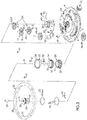
- FIG. 1 On the FIG. 1 a self-winding horological movement 1 is shown. This movement 1 is intended to equip a wristwatch, able to be worn on the wrist.
- the movement 1 comprises, first of all, a plate 2, which is in the form of a rigid part (preferably made of metal, for example steel), intended to form a support for various components of the movement, fixed or mobile .
- the plate 2 has a lower face 3 and an upper face 4, opposite to the lower face 3.
- the movement 1 comprises, secondly, a barrel 5 mounted in rotation relative to the plate 3 and provided with a primary toothed wheel 6.
- the barrel comprises a barrel shaft 7 by which the barrel is rotatably mounted on the plate 2, a barrel drum 8, and a barrel spring (not shown) secured, by an internal end, to the barrel shaft 7 and, by an outer end, of the barrel drum 8.
- the barrel is provided with a secondary toothed wheel 9 (also called a "ratchet") and separate from the primary toothed wheel 6.
- a secondary toothed wheel 9 also called a "ratchet”
- the movement 1 comprises, thirdly, a winder 10 which comprises a winding stem 11 carrying, at an outer end, a winding crown 12.
- the winder comprises a winding mechanism 13 by which the winding rod 11 engages, in a winding position, the secondary toothed wheel 9 of the barrel 5 in order to ensure its rotation manually and thus to arm the spring.
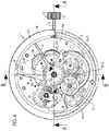
- the movement 1 comprises, in the fourth place, a carriageway 14 mounted in rotation with respect to the plate 2 about a central axis A.
- the causeway includes a 15 minute barrel which carries a 16 minute hand.
- the carriageway 14 is in a gear relationship with the primary toothed wheel 6 of the barrel by means of a timer gear 17. More precisely, and according to one embodiment illustrated in particular on the FIG. 7 , the carriageway 14 comprises a minute pinion 18, integral with the minute barrel 15 (or integrally formed therewith), and the timer gear 17 comprises a timer wheel 19.1 meshing with the minute pinion.
- the timer gear 17 is mounted in rotation with respect to the plate 2.
- the movement 1 comprises, in the fifth place, a mobile 20 of the hours, mounted in rotation with respect to the plate 2 around the central axis A.
- the hours mobile comprises a 21 hour cannon which carries a 22 hour hand.
- the hours mobile 20 is in a gear relationship with the roadway 14. More precisely, and according to an embodiment illustrated in FIG. FIG. 7 , the hours mobile comprises an hours pinion 23, integral with the hours barrel 21 (or integrally formed therewith), and the movement 1 comprises a pinion 24 which rotates the hours mobile to the roadway 14 in a gear ratio R of 1/12.
- the gears are chosen so that the gear ratio R is equal to 1/12.
- the carriageway 14, including the 15 minute barrel and the 16 minute hand, is located on the side of the upper face 4 of the plate 2.
- the 20 hour mobile, including the 21 hour barrel and the 22 hour hand, is located on the side of the upper face 4 of plate 2.
- the movement 1 comprises, in the sixth place, an oscillating mass in the form of a rotor 25 mounted in rotation with respect to the plate 2 around the central axis A, on the same side of the plate 2 as the roadway 14 and the mobile. 20 hours - in this case on the side of the upper face 4 of the plate.
- the rim 27 is in the form of a solid disc, but it could be perforated.
- the rim is a solid disc made of a transparent material, e.g. in industrial sapphire.
- the heavy annular sector 28 appears, for example. in the form of a half-ring made of a material whose density is greater than that of the material of the rim 27.
- the heavy annular sector is made of brass.
- the attachment of the heavy annular sector 28 to the rim 27 is e.g. produced by screwing, riveting, crimping or gluing.
- the movement 1 comprises, in the seventh place, a booster shaft 29 integral with the central hub 26 and by which the latter is mounted in rotation with respect to the plate 2.
- the booster shaft 29 is preferably in the form of a hollow cylinder, produced for example. in steel.
- the booster shaft and the central hub could form a single piece. However, in the example illustrated, the booster shaft and the central hub form two separate parts fixed to one another. According to a particular embodiment, the central hub is driven onto an upper end of the booster shaft.
- the 15 minute barrel and the 21 hour barrel are mounted coaxially around the booster shaft 29, the minute hand 16 and the hour hand 22 being located between the plate 2 and the rim 27 of the rotor .
- this arrangement makes it possible to position the hands 16, 22 as close as possible to a possible dial or a crown bearing a time scale, for the benefit of readability of the hours.
- the bearing 30 is advantageously mounted on an intermediate bridge 34 fixed on the plate 2.
- the fixed ring 31 is an inner ring of the bearing 30, and the movable ring 32 is an outer ring.
- the booster shaft 29 is driven out on the movable ring 32 located outside the bearing.
- the movable ring 32 preferably carries a toothed crown 37 in a gear relationship with the barrel 5, via a reduction gear 38 (visible on the FIG. 5 ). More precisely, the reduction gear is in a gear relationship with the secondary toothed wheel 9 (cog) of the barrel 5.
- the guns 15, 21 freely surround the booster shaft 29.
- the respective internal diameters of the barrels 15, 21 are greater than the external diameter of the booster shaft, at least for the part of this booster shaft located inside the two barrels.
- the movement 1 advantageously comprises a sleeve 39 surrounding the enhancer shaft, this sleeve being fixed relative to the plate 2.
- the hours barrel 20 and the minutes barrel 15 are mounted on the sleeve.
- the sleeve is integral (eg by driving) an upper bridge 40 fixed on the plate 2. More precisely, in the example illustrated, the upper bridge is fixed on the intermediate bridge 34.
- the inner ring 31 of the bearing 30 is fixed to the intermediate bridge by the central screw 35, this central screw also securing to this bridge the intermediate part 36, which has a bottom with a central hole for the passage of the central screw and a tube rigid in which the head of this central screw is located, this rigid tube being located inside a central opening presented by the booster shaft, this booster shaft forming a rotating tube.
- the upper deck 40 is clearly visible on the FIG. 2 and FIG. 3 .
- the attachment of the upper deck to the intermediate deck 34 is e.g. carried out by means of screws 41, here three in number.
- the upper bridge is pierced with holes 42 and carries pins 43 for guiding in rotation the moving parts of the movement 2, and in particular components of the timer gear 17.
- a first lanterning is advantageously provided at the interface between the sleeve 39 and the hour barrel 21 to allow the latter to rotate (with the hour hand 22) relative to the sleeve.
- a second lanterning is advantageously provided at the interface between the hour barrel 21 and the minute barrel 15 to allow the latter to rotate (with the minute hand 16) relative to the hour barrel.
- the barrel 5 is mounted on the side of an internal face 44 (turned towards the plate 2) of the upper bridge 40 (and more precisely between the intermediate bridge 34 and the plate 2), while the roadway 14, the mobile 20 of the hours and the rotor 25 are mounted on the side of an outer face 45 (opposite to the plate 2) of the upper bridge.
- the axis 49 crosses not only the upper bridge 40 but also the intermediate bridge 34.
- the movement 1 can also be equipped with a small second hand 50, off-center with respect to the central axis A.
- the small seconds hand is driven out on an axis 51 integral with a seconds wheel 52, in gear relation with the roadway 14 in a 1/60 ratio.
- the movement 1 comprises a bearing 53, provided with a guide ring 54 which surrounds the roadway 14, and a foot 55 by which the bearing 53 is fixed to the upper deck 40.
- the fact that the rotor 25 is located on the same side as the time display i.e. the hands 15, 22
- the time display i.e. the hands 15, 22
- the fact that the rotor 25 surmounts the needles 15, 22 makes it possible to position them as close as possible to the body of the movement and an hour graduation which may be located on the rear face of this body, for the benefit of the readability of the display.
- the watch movement which has just been described can easily also have an additional time display located on the side of the front face of plate 2.
- the second display possibly corresponding for example to a different time zone from that of the first display.
Landscapes
- Physics & Mathematics (AREA)
- General Physics & Mathematics (AREA)
- Electromechanical Clocks (AREA)
- Measurement Of Unknown Time Intervals (AREA)
Claims (12)
- Uhrwerk (1) mit automatischem Aufzug, welches umfasst:- eine Werkplatte (2),- ein Federhaus (5), das in Bezug auf die Werkplatte (2) drehbar angebracht ist und ein Primärzahnrad (6) trägt,- ein Minutenrohr (14), das in Bezug auf die Werkplatte um eine Mittelachse (A) drehbar angebracht ist und mittels eines Zeigerräderwerks (17) mit dem Primärzahnrad (6) des Federhauses (5) in Getriebebeziehung steht, wobei dieses Minutenrohr (14) eine Minutenkanone (15) umfasst, die einen Minutenzeiger (16) trägt,- einen Stundendrehteil (20), der in Bezug auf die Werkplatte um die Mittelachse drehbar angebracht ist und mit dem Minutenrohr (14) in Getriebebeziehung steht, wobei dieser Stundendrehteil (20) eine Stundenkanone (21) umfasst, die einen Stundenzeiger (22) trägt,- eine Schwungmasse in Form eines Rotors (25), der in Bezug auf die Werkplatte (2) um die Mittelachse (A) drehbar auf der gleichen Seite der Werkplatte wie das Minutenrohr (14) und der Stundendrehteil (20) angebracht ist, wobei dieser Rotor umfasst:wobei dieses Uhrwerk dadurch gekennzeichnet ist, dass es eine Hebewelle (29) umfasst, die fest mit der Mittelnabe (26) verbunden ist und durch die diese Nabe in Bezug auf die Werkplatte (2) drehbar angebracht ist; und dadurch, dass die Minutenkanone und die Stundenkanone koaxial um die Hebewelle herum, die durch sie hindurch verläuft, angebracht sind, wobei sich der Minutenzeiger und der Stundenzeiger zwischen der Werkplatte (2) und der Felge (27) des Rotors befinden.∘ eine Mittelnabe (26), die mit dem Federhaus in Getriebebeziehung steht,∘ eine Felge (27), die fest mit der Mittelnabe verbunden ist,∘ einen schweren Ringsektor (28), der fest mit der Felge verbunden ist,
- Uhrwerk (1) nach Anspruch 1, dadurch gekennzeichnet, dass es ein Lager (30) umfasst, das mit einem in Bezug auf die Werkplatte (2) festen Ring (31), einem in Bezug auf den festen Ring (31) um die Mittelachse (A) drehbeweglichen Ring (32), und Wälzelementen (33) versehen ist, die zwischen den zwei Ringen eingefügt sind; und dadurch, dass die Hebewelle (29) fest mit dem beweglichen Ring verbunden ist.
- Uhrwerk (1) nach Anspruch 2, dadurch gekennzeichnet, dass der drehbewegliche Ring (32) einen Zahnkranz (37) trägt, der mittels eines Untersetzungsräderwerks (38) mit dem Federhaus (5) in Getriebebeziehung steht.
- Uhrwerk (1) nach Anspruch 3, dadurch gekennzeichnet, dass das Federhaus (5) ein Sekundärzahnrad (9) trägt, das sich vom Primärzahnrad (6) unterscheidet und mit dem das Untersetzungsräderwerk in Getriebebeziehung steht.
- Uhrwerk (1) nach einem der Ansprüche 2 bis 4, dadurch gekennzeichnet, dass das Lager (30) auf einer Brücke (34) angebracht ist, die auf der Werkplatte (2) befestigt ist.
- Uhrwerk (1) nach einem der Ansprüche 2 bis 5, dadurch gekennzeichnet, dass es sich bei dem festen Ring (31) um einen Innenring handelt, und es sich bei dem drehbeweglichen Ring (32) um einen Außenring handelt.
- Uhrwerk (1) nach den Ansprüchen 5 und 6 in Kombination, dadurch gekennzeichnet, dass der Innenring (31) des Lagers (30) über eine Mittelschraube (35) an der Brücke (34) befestigt ist, wobei diese Mittelschraube weiter ein Zwischenstück (36), das einen Boden mit einem Mittelloch für den Durchtritt der Mittelschraube und ein starres Rohr aufweist, in dem sich der Kopf dieser Mittelschraube befindet, fest mit dieser Brücke verbindet, wobei sich dieses starre Rohr im Inneren einer Mittelöffnung befindet, welche die Hebewelle aufweist, wobei diese Hebewelle ein Drehrohr bildet.
- Uhrwerk (1) nach einem der vorstehenden Ansprüche, dadurch gekennzeichnet, dass es eine Fassung (39) umfasst, die in Bezug auf die Werkplatte (2) fest ist und auf der die Stundenkanone (21) und die Minutenkanone (15) angebracht sind, wobei diese feste Fassung die Hebewelle umgibt.
- Uhrwerk (1) nach Anspruch 8, dadurch gekennzeichnet, dass:- die Stundenkanone (21) auf die Fassung (39) gesetzt ist,- die Minutenkanone (15) auf die Stundenkanone (21) gesetzt ist.
- Uhrwerk (1) nach Anspruch 8 oder Anspruch 9, dadurch gekennzeichnet, dass die Fassung fest auf einer oberen Brücke (40) angebracht ist, die auf der Werkplatte (2) befestigt ist, wobei diese obere Brücke eine Innenseite (44) auf Seite der Werkplatte (2) und eine gegenüberliegende Außenseite (45) aufweist.
- Uhrwerk (1) nach Anspruch 10, dadurch gekennzeichnet, dass das Federhaus (5) auf Seite der Innenseite (44) der oberen Brücke (40) angebracht ist, während das Minutenrohr (14), der Stundendrehteil (20) und der Rotor (25) auf Seite der Außenseite dieser oberen Brücke angebracht sind.
- Uhrwerk (1) nach Anspruch 11, dadurch gekennzeichnet, dass es umfasst:- ein Zeigerräderwerk (17), das mit einem Minutentrieb (18), welcher fest mit der Minutenkanone (15) verbunden ist, in Getriebeeingriff steht, wobei dieses Zeigerräderwerk in Bezug auf die obere Brücke (40) auf Seite der Außenseite (44) derselben drehbar angebracht ist,- einen Wenderdrehteil (46), welcher umfasst:∘ ein oberes Rad (47), das sich auf Seite der Außenseite (45) der oberen Brücke befindet und mit dem Zeigerräderwerk (17) in Getriebeeingriff steht,∘ ein unteres Rad (48), das sich auf Seite der Innenseite (44) der oberen Brücke befindet und drehfest mit dem oberen Rad verbunden ist und mit dem Primärzahnrad (6) des Federhauses (5) in Getriebebeziehung steht,∘ eine Achse (49), die durch die obere Brücke (40) hindurch das obere Rad und das untere Rad miteinander verbindet.
Priority Applications (4)
| Application Number | Priority Date | Filing Date | Title |
|---|---|---|---|
| EP18196380.2A EP3627232B1 (de) | 2018-09-24 | 2018-09-24 | Uhrwerk mit automatischem aufzug, das stundenzeiger auf der seite des rotors umfasst |
| US16/545,306 US11550260B2 (en) | 2018-09-24 | 2019-08-20 | Horological movement with automatic winding having time-displaying hands located on the same side as the rotor |
| JP2019166861A JP6728457B2 (ja) | 2018-09-24 | 2019-09-13 | ローターと同じ側に位置する時間表示針を有する自動巻き機能付き計時器用ムーブメント |
| CN201910902745.XA CN110941171B (zh) | 2018-09-24 | 2019-09-23 | 具有与转子位于同一侧的时间显示指针的自动上条钟表机芯 |
Applications Claiming Priority (1)
| Application Number | Priority Date | Filing Date | Title |
|---|---|---|---|
| EP18196380.2A EP3627232B1 (de) | 2018-09-24 | 2018-09-24 | Uhrwerk mit automatischem aufzug, das stundenzeiger auf der seite des rotors umfasst |
Publications (2)
| Publication Number | Publication Date |
|---|---|
| EP3627232A1 EP3627232A1 (de) | 2020-03-25 |
| EP3627232B1 true EP3627232B1 (de) | 2021-05-05 |
Family
ID=63683106
Family Applications (1)
| Application Number | Title | Priority Date | Filing Date |
|---|---|---|---|
| EP18196380.2A Active EP3627232B1 (de) | 2018-09-24 | 2018-09-24 | Uhrwerk mit automatischem aufzug, das stundenzeiger auf der seite des rotors umfasst |
Country Status (4)
| Country | Link |
|---|---|
| US (1) | US11550260B2 (de) |
| EP (1) | EP3627232B1 (de) |
| JP (1) | JP6728457B2 (de) |
| CN (1) | CN110941171B (de) |
Family Cites Families (18)
| Publication number | Priority date | Publication date | Assignee | Title |
|---|---|---|---|---|
| CH426651A (fr) * | 1964-12-10 | 1966-05-14 | Zenith Montres | Montre à remontage automatique |
| CH685363B5 (fr) * | 1993-05-21 | 1995-12-29 | Grandjean Eric M | Montre. |
| JPH1172580A (ja) * | 1997-08-29 | 1999-03-16 | Seiko Instr Inc | 腕時計 |
| JPH11183645A (ja) * | 1997-12-18 | 1999-07-09 | Seiko Instruments Inc | 自動巻時計 |
| CH692537A5 (fr) * | 1998-10-23 | 2002-07-15 | Perrelet Sa | Montre à remontage automatique. |
| JP2004170270A (ja) | 2002-11-20 | 2004-06-17 | Seiko Instruments Inc | 規正装置を備えた自動巻時計 |
| JP4376536B2 (ja) | 2003-03-27 | 2009-12-02 | セイコーインスツル株式会社 | 時分発停レバーを有するクロノグラフ時計 |
| JP4475630B2 (ja) | 2004-01-27 | 2010-06-09 | セイコーインスツル株式会社 | 変形セグメント歯車を含むぜんまい巻き状態表示装置付き時計 |
| WO2006103560A2 (fr) * | 2005-03-30 | 2006-10-05 | Dth Dubois Technique Horlogere Sa | Dispositif de remontage automatique |
| DE102007046689B4 (de) * | 2007-06-01 | 2009-09-17 | Konrad Damasko | Mechanischer Aufzug für Armbanduhren sowie Armbanduhr mit einem solchen Aufzug |
| EP2073078B1 (de) | 2007-12-21 | 2012-11-07 | Omega SA | Bistabiler Hammer für Chronographenmechanismus |
| CH703964B1 (fr) | 2010-10-26 | 2015-07-15 | Soprod Sa | Mouvement de montre automatique avec masse oscillante disposée du côté de la platine. |
| EP2544055B1 (de) * | 2011-07-07 | 2017-11-08 | Blancpain S.A. | Anzeige einer physikalischen Größe auf einem Uhranzeigeträger |
| EP2551731A1 (de) | 2011-07-28 | 2013-01-30 | Cartier Création Studio S.A. | Schwungmasse, die auf die Außenseite eines Uhrwerks geschwenkt ist, und mit einer solchen Schwungmasse ausgestattetes Uhrwerk |
| CN204086820U (zh) * | 2014-09-09 | 2015-01-07 | 杭州手表有限公司 | 一种薄型机械表环形自动上条机构 |
| EP3021173B1 (de) * | 2014-11-14 | 2017-05-24 | Blancpain S.A. | Ringförmige Schwungmasse und Uhr, die eine solche Schwungmasse umfasst |
| CH713222A1 (fr) * | 2016-12-13 | 2018-06-15 | Cartier Int Ag | Mouvement horloger à remontage automatique. |
| CH713302A2 (fr) * | 2016-12-23 | 2018-06-29 | Mft Et Fabrique De Montres Et Chronometres Ulysse Nardin Le Locle S A | Dispositif de conversion de déplacements, par exemple pour systèmes de remontage automatique de pièces d'horlogerie. |
-
2018
- 2018-09-24 EP EP18196380.2A patent/EP3627232B1/de active Active
-
2019
- 2019-08-20 US US16/545,306 patent/US11550260B2/en active Active
- 2019-09-13 JP JP2019166861A patent/JP6728457B2/ja active Active
- 2019-09-23 CN CN201910902745.XA patent/CN110941171B/zh active Active
Also Published As
| Publication number | Publication date |
|---|---|
| JP6728457B2 (ja) | 2020-07-22 |
| US20200096942A1 (en) | 2020-03-26 |
| CN110941171A (zh) | 2020-03-31 |
| JP2020052040A (ja) | 2020-04-02 |
| EP3627232A1 (de) | 2020-03-25 |
| CN110941171B (zh) | 2021-06-22 |
| US11550260B2 (en) | 2023-01-10 |
Similar Documents
| Publication | Publication Date | Title |
|---|---|---|
| CH684619B5 (fr) | Pièce d'horlogerie à affichage universel de l'heure. | |
| EP1228403B1 (de) | Zeitanzeiger mit mechanischer regulierung | |
| EP1582943A1 (de) | Uhrwerk mit mehreren Federhäusern | |
| EP1139182B1 (de) | Anzeigemechanismus der Gangreserve einer Uhr und mit diesem Mechanismus versehene Uhr | |
| CH693833A5 (fr) | Mécanisme d'horlogerie incluant un tourbillon. | |
| CH705832B1 (fr) | Mécanisme de calendrier et pièce d'horlogerie comportant un tel mécanisme. | |
| EP3627232B1 (de) | Uhrwerk mit automatischem aufzug, das stundenzeiger auf der seite des rotors umfasst | |
| CH715378A2 (fr) | Mouvement horloger à remontage automatique ayant des aiguilles d'affichage de l'heure situées du côté de la masse oscillante. | |
| EP3246763B1 (de) | Schnellkorrekturmechanismus für uhr | |
| EP3555707B1 (de) | Uhrwerk mit automatischer montage | |
| EP3501842B1 (de) | Anzeigevorrichtung mit rollen | |
| CH710450B1 (fr) | Pièce d'horlogerie munie d'un affichage orbital. | |
| CH720191A2 (fr) | Pièce d'horlogerie mécanique à tourbillon surélevé | |
| FR3141536A1 (fr) | Piece d’horlogerie mécanique à tourbillon surélevé | |
| CH370709A (fr) | Elément de bâti mince pour mouvement d'horlogerie | |
| EP4080292B1 (de) | Uhrwerkmechanismus zur anzeige von mindestens einer einzigen zeitanzeige und uhrwerk mit einem solchen mechanismus | |
| EP1353244B1 (de) | Uhr mit länglichem Gehäuse | |
| CH721007A1 (fr) | Module horloger pour mouvement horloger | |
| CH702507A2 (fr) | Mouvement et pièce d'horlogerie. | |
| CH721904B1 (fr) | Pièce d'horlogerie munie d'un cache | |
| CH333987A (fr) | Montre à deux paires d'aiguilles | |
| CH717960B1 (fr) | Mécanisme horloger d'affichage de l'indication de l'heure unique et pièce d'horlogerie le comprenant. | |
| CH332539A (fr) | Mécanisme d'entraînement de l'aiguille des minutes d'une pièce d'horlogerie sans roue de grande moyenne au centre | |
| CH693291A5 (fr) | Montre universelle. | |
| CH332538A (fr) | Mécanisme d'entraînement de l'aiguille des minutes d'une pièce d'horlogerie sans roue de grande moyenne au centre |
Legal Events
| Date | Code | Title | Description |
|---|---|---|---|
| PUAI | Public reference made under article 153(3) epc to a published international application that has entered the european phase |
Free format text: ORIGINAL CODE: 0009012 |
|
| STAA | Information on the status of an ep patent application or granted ep patent |
Free format text: STATUS: THE APPLICATION HAS BEEN PUBLISHED |
|
| AK | Designated contracting states |
Kind code of ref document: A1 Designated state(s): AL AT BE BG CH CY CZ DE DK EE ES FI FR GB GR HR HU IE IS IT LI LT LU LV MC MK MT NL NO PL PT RO RS SE SI SK SM TR |
|
| AX | Request for extension of the european patent |
Extension state: BA ME |
|
| STAA | Information on the status of an ep patent application or granted ep patent |
Free format text: STATUS: REQUEST FOR EXAMINATION WAS MADE |
|
| 17P | Request for examination filed |
Effective date: 20200925 |
|
| RBV | Designated contracting states (corrected) |
Designated state(s): AL AT BE BG CH CY CZ DE DK EE ES FI FR GB GR HR HU IE IS IT LI LT LU LV MC MK MT NL NO PL PT RO RS SE SI SK SM TR |
|
| GRAP | Despatch of communication of intention to grant a patent |
Free format text: ORIGINAL CODE: EPIDOSNIGR1 |
|
| STAA | Information on the status of an ep patent application or granted ep patent |
Free format text: STATUS: GRANT OF PATENT IS INTENDED |
|
| INTG | Intention to grant announced |
Effective date: 20210223 |
|
| GRAS | Grant fee paid |
Free format text: ORIGINAL CODE: EPIDOSNIGR3 |
|
| GRAA | (expected) grant |
Free format text: ORIGINAL CODE: 0009210 |
|
| STAA | Information on the status of an ep patent application or granted ep patent |
Free format text: STATUS: THE PATENT HAS BEEN GRANTED |
|
| AK | Designated contracting states |
Kind code of ref document: B1 Designated state(s): AL AT BE BG CH CY CZ DE DK EE ES FI FR GB GR HR HU IE IS IT LI LT LU LV MC MK MT NL NO PL PT RO RS SE SI SK SM TR |
|
| REG | Reference to a national code |
Ref country code: GB Ref legal event code: FG4D Free format text: NOT ENGLISH |
|
| REG | Reference to a national code |
Ref country code: CH Ref legal event code: EP Ref country code: CH Ref legal event code: NV Representative=s name: ICB INGENIEURS CONSEILS EN BREVETS SA, CH |
|
| REG | Reference to a national code |
Ref country code: AT Ref legal event code: REF Ref document number: 1390571 Country of ref document: AT Kind code of ref document: T Effective date: 20210515 |
|
| REG | Reference to a national code |
Ref country code: IE Ref legal event code: FG4D Free format text: LANGUAGE OF EP DOCUMENT: FRENCH |
|
| REG | Reference to a national code |
Ref country code: DE Ref legal event code: R096 Ref document number: 602018016535 Country of ref document: DE |
|
| REG | Reference to a national code |
Ref country code: LT Ref legal event code: MG9D |
|
| REG | Reference to a national code |
Ref country code: AT Ref legal event code: MK05 Ref document number: 1390571 Country of ref document: AT Kind code of ref document: T Effective date: 20210505 |
|
| PG25 | Lapsed in a contracting state [announced via postgrant information from national office to epo] |
Ref country code: FI Free format text: LAPSE BECAUSE OF FAILURE TO SUBMIT A TRANSLATION OF THE DESCRIPTION OR TO PAY THE FEE WITHIN THE PRESCRIBED TIME-LIMIT Effective date: 20210505 Ref country code: HR Free format text: LAPSE BECAUSE OF FAILURE TO SUBMIT A TRANSLATION OF THE DESCRIPTION OR TO PAY THE FEE WITHIN THE PRESCRIBED TIME-LIMIT Effective date: 20210505 Ref country code: LT Free format text: LAPSE BECAUSE OF FAILURE TO SUBMIT A TRANSLATION OF THE DESCRIPTION OR TO PAY THE FEE WITHIN THE PRESCRIBED TIME-LIMIT Effective date: 20210505 Ref country code: AT Free format text: LAPSE BECAUSE OF FAILURE TO SUBMIT A TRANSLATION OF THE DESCRIPTION OR TO PAY THE FEE WITHIN THE PRESCRIBED TIME-LIMIT Effective date: 20210505 Ref country code: BG Free format text: LAPSE BECAUSE OF FAILURE TO SUBMIT A TRANSLATION OF THE DESCRIPTION OR TO PAY THE FEE WITHIN THE PRESCRIBED TIME-LIMIT Effective date: 20210805 |
|
| PG25 | Lapsed in a contracting state [announced via postgrant information from national office to epo] |
Ref country code: IS Free format text: LAPSE BECAUSE OF FAILURE TO SUBMIT A TRANSLATION OF THE DESCRIPTION OR TO PAY THE FEE WITHIN THE PRESCRIBED TIME-LIMIT Effective date: 20210905 Ref country code: GR Free format text: LAPSE BECAUSE OF FAILURE TO SUBMIT A TRANSLATION OF THE DESCRIPTION OR TO PAY THE FEE WITHIN THE PRESCRIBED TIME-LIMIT Effective date: 20210806 Ref country code: PL Free format text: LAPSE BECAUSE OF FAILURE TO SUBMIT A TRANSLATION OF THE DESCRIPTION OR TO PAY THE FEE WITHIN THE PRESCRIBED TIME-LIMIT Effective date: 20210505 Ref country code: NO Free format text: LAPSE BECAUSE OF FAILURE TO SUBMIT A TRANSLATION OF THE DESCRIPTION OR TO PAY THE FEE WITHIN THE PRESCRIBED TIME-LIMIT Effective date: 20210805 Ref country code: LV Free format text: LAPSE BECAUSE OF FAILURE TO SUBMIT A TRANSLATION OF THE DESCRIPTION OR TO PAY THE FEE WITHIN THE PRESCRIBED TIME-LIMIT Effective date: 20210505 Ref country code: PT Free format text: LAPSE BECAUSE OF FAILURE TO SUBMIT A TRANSLATION OF THE DESCRIPTION OR TO PAY THE FEE WITHIN THE PRESCRIBED TIME-LIMIT Effective date: 20210906 Ref country code: SE Free format text: LAPSE BECAUSE OF FAILURE TO SUBMIT A TRANSLATION OF THE DESCRIPTION OR TO PAY THE FEE WITHIN THE PRESCRIBED TIME-LIMIT Effective date: 20210505 Ref country code: RS Free format text: LAPSE BECAUSE OF FAILURE TO SUBMIT A TRANSLATION OF THE DESCRIPTION OR TO PAY THE FEE WITHIN THE PRESCRIBED TIME-LIMIT Effective date: 20210505 |
|
| REG | Reference to a national code |
Ref country code: NL Ref legal event code: MP Effective date: 20210505 |
|
| PG25 | Lapsed in a contracting state [announced via postgrant information from national office to epo] |
Ref country code: NL Free format text: LAPSE BECAUSE OF FAILURE TO SUBMIT A TRANSLATION OF THE DESCRIPTION OR TO PAY THE FEE WITHIN THE PRESCRIBED TIME-LIMIT Effective date: 20210505 |
|
| PG25 | Lapsed in a contracting state [announced via postgrant information from national office to epo] |
Ref country code: RO Free format text: LAPSE BECAUSE OF FAILURE TO SUBMIT A TRANSLATION OF THE DESCRIPTION OR TO PAY THE FEE WITHIN THE PRESCRIBED TIME-LIMIT Effective date: 20210505 Ref country code: CZ Free format text: LAPSE BECAUSE OF FAILURE TO SUBMIT A TRANSLATION OF THE DESCRIPTION OR TO PAY THE FEE WITHIN THE PRESCRIBED TIME-LIMIT Effective date: 20210505 Ref country code: DK Free format text: LAPSE BECAUSE OF FAILURE TO SUBMIT A TRANSLATION OF THE DESCRIPTION OR TO PAY THE FEE WITHIN THE PRESCRIBED TIME-LIMIT Effective date: 20210505 Ref country code: SM Free format text: LAPSE BECAUSE OF FAILURE TO SUBMIT A TRANSLATION OF THE DESCRIPTION OR TO PAY THE FEE WITHIN THE PRESCRIBED TIME-LIMIT Effective date: 20210505 Ref country code: SK Free format text: LAPSE BECAUSE OF FAILURE TO SUBMIT A TRANSLATION OF THE DESCRIPTION OR TO PAY THE FEE WITHIN THE PRESCRIBED TIME-LIMIT Effective date: 20210505 Ref country code: EE Free format text: LAPSE BECAUSE OF FAILURE TO SUBMIT A TRANSLATION OF THE DESCRIPTION OR TO PAY THE FEE WITHIN THE PRESCRIBED TIME-LIMIT Effective date: 20210505 Ref country code: ES Free format text: LAPSE BECAUSE OF FAILURE TO SUBMIT A TRANSLATION OF THE DESCRIPTION OR TO PAY THE FEE WITHIN THE PRESCRIBED TIME-LIMIT Effective date: 20210505 |
|
| REG | Reference to a national code |
Ref country code: DE Ref legal event code: R097 Ref document number: 602018016535 Country of ref document: DE |
|
| PLBE | No opposition filed within time limit |
Free format text: ORIGINAL CODE: 0009261 |
|
| STAA | Information on the status of an ep patent application or granted ep patent |
Free format text: STATUS: NO OPPOSITION FILED WITHIN TIME LIMIT |
|
| 26N | No opposition filed |
Effective date: 20220208 |
|
| REG | Reference to a national code |
Ref country code: BE Ref legal event code: MM Effective date: 20210930 |
|
| PG25 | Lapsed in a contracting state [announced via postgrant information from national office to epo] |
Ref country code: IS Free format text: LAPSE BECAUSE OF FAILURE TO SUBMIT A TRANSLATION OF THE DESCRIPTION OR TO PAY THE FEE WITHIN THE PRESCRIBED TIME-LIMIT Effective date: 20210905 Ref country code: MC Free format text: LAPSE BECAUSE OF FAILURE TO SUBMIT A TRANSLATION OF THE DESCRIPTION OR TO PAY THE FEE WITHIN THE PRESCRIBED TIME-LIMIT Effective date: 20210505 Ref country code: AL Free format text: LAPSE BECAUSE OF FAILURE TO SUBMIT A TRANSLATION OF THE DESCRIPTION OR TO PAY THE FEE WITHIN THE PRESCRIBED TIME-LIMIT Effective date: 20210505 |
|
| PG25 | Lapsed in a contracting state [announced via postgrant information from national office to epo] |
Ref country code: LU Free format text: LAPSE BECAUSE OF NON-PAYMENT OF DUE FEES Effective date: 20210924 Ref country code: IT Free format text: LAPSE BECAUSE OF FAILURE TO SUBMIT A TRANSLATION OF THE DESCRIPTION OR TO PAY THE FEE WITHIN THE PRESCRIBED TIME-LIMIT Effective date: 20210505 Ref country code: IE Free format text: LAPSE BECAUSE OF NON-PAYMENT OF DUE FEES Effective date: 20210924 Ref country code: BE Free format text: LAPSE BECAUSE OF NON-PAYMENT OF DUE FEES Effective date: 20210930 |
|
| PG25 | Lapsed in a contracting state [announced via postgrant information from national office to epo] |
Ref country code: CY Free format text: LAPSE BECAUSE OF FAILURE TO SUBMIT A TRANSLATION OF THE DESCRIPTION OR TO PAY THE FEE WITHIN THE PRESCRIBED TIME-LIMIT Effective date: 20210505 |
|
| PG25 | Lapsed in a contracting state [announced via postgrant information from national office to epo] |
Ref country code: HU Free format text: LAPSE BECAUSE OF FAILURE TO SUBMIT A TRANSLATION OF THE DESCRIPTION OR TO PAY THE FEE WITHIN THE PRESCRIBED TIME-LIMIT; INVALID AB INITIO Effective date: 20180924 |
|
| P01 | Opt-out of the competence of the unified patent court (upc) registered |
Effective date: 20230701 |
|
| PG25 | Lapsed in a contracting state [announced via postgrant information from national office to epo] |
Ref country code: MK Free format text: LAPSE BECAUSE OF FAILURE TO SUBMIT A TRANSLATION OF THE DESCRIPTION OR TO PAY THE FEE WITHIN THE PRESCRIBED TIME-LIMIT Effective date: 20210505 |
|
| PG25 | Lapsed in a contracting state [announced via postgrant information from national office to epo] |
Ref country code: MT Free format text: LAPSE BECAUSE OF FAILURE TO SUBMIT A TRANSLATION OF THE DESCRIPTION OR TO PAY THE FEE WITHIN THE PRESCRIBED TIME-LIMIT Effective date: 20210505 |
|
| REG | Reference to a national code |
Ref country code: CH Ref legal event code: U11 Free format text: ST27 STATUS EVENT CODE: U-0-0-U10-U11 (AS PROVIDED BY THE NATIONAL OFFICE) Effective date: 20251001 |
|
| PGFP | Annual fee paid to national office [announced via postgrant information from national office to epo] |
Ref country code: DE Payment date: 20250820 Year of fee payment: 8 |
|
| PGFP | Annual fee paid to national office [announced via postgrant information from national office to epo] |
Ref country code: GB Payment date: 20250822 Year of fee payment: 8 |
|
| PGFP | Annual fee paid to national office [announced via postgrant information from national office to epo] |
Ref country code: FR Payment date: 20250821 Year of fee payment: 8 |
|
| PG25 | Lapsed in a contracting state [announced via postgrant information from national office to epo] |
Ref country code: TR Free format text: LAPSE BECAUSE OF FAILURE TO SUBMIT A TRANSLATION OF THE DESCRIPTION OR TO PAY THE FEE WITHIN THE PRESCRIBED TIME-LIMIT Effective date: 20210505 |
|
| PGFP | Annual fee paid to national office [announced via postgrant information from national office to epo] |
Ref country code: CH Payment date: 20251001 Year of fee payment: 8 |