EP3555886B1 - Procédés, codeur et décodeur de gestion de coefficients de fréquence spectrale de ligne - Google Patents
Procédés, codeur et décodeur de gestion de coefficients de fréquence spectrale de ligne Download PDFInfo
- Publication number
- EP3555886B1 EP3555886B1 EP17811886.5A EP17811886A EP3555886B1 EP 3555886 B1 EP3555886 B1 EP 3555886B1 EP 17811886 A EP17811886 A EP 17811886A EP 3555886 B1 EP3555886 B1 EP 3555886B1
- Authority
- EP
- European Patent Office
- Prior art keywords
- lsf
- coefficients
- shape
- gain
- pvq
- Prior art date
- Legal status (The legal status is an assumption and is not a legal conclusion. Google has not performed a legal analysis and makes no representation as to the accuracy of the status listed.)
- Active
Links
Images



Classifications
-
- G—PHYSICS
- G10—MUSICAL INSTRUMENTS; ACOUSTICS
- G10L—SPEECH ANALYSIS TECHNIQUES OR SPEECH SYNTHESIS; SPEECH RECOGNITION; SPEECH OR VOICE PROCESSING TECHNIQUES; SPEECH OR AUDIO CODING OR DECODING
- G10L19/00—Speech or audio signals analysis-synthesis techniques for redundancy reduction, e.g. in vocoders; Coding or decoding of speech or audio signals, using source filter models or psychoacoustic analysis
- G10L19/04—Speech or audio signals analysis-synthesis techniques for redundancy reduction, e.g. in vocoders; Coding or decoding of speech or audio signals, using source filter models or psychoacoustic analysis using predictive techniques
- G10L19/06—Determination or coding of the spectral characteristics, e.g. of the short-term prediction coefficients
- G10L19/07—Line spectrum pair [LSP] vocoders
-
- G—PHYSICS
- G10—MUSICAL INSTRUMENTS; ACOUSTICS
- G10L—SPEECH ANALYSIS TECHNIQUES OR SPEECH SYNTHESIS; SPEECH RECOGNITION; SPEECH OR VOICE PROCESSING TECHNIQUES; SPEECH OR AUDIO CODING OR DECODING
- G10L19/00—Speech or audio signals analysis-synthesis techniques for redundancy reduction, e.g. in vocoders; Coding or decoding of speech or audio signals, using source filter models or psychoacoustic analysis
- G10L19/04—Speech or audio signals analysis-synthesis techniques for redundancy reduction, e.g. in vocoders; Coding or decoding of speech or audio signals, using source filter models or psychoacoustic analysis using predictive techniques
- G10L19/06—Determination or coding of the spectral characteristics, e.g. of the short-term prediction coefficients
-
- G—PHYSICS
- G10—MUSICAL INSTRUMENTS; ACOUSTICS
- G10L—SPEECH ANALYSIS TECHNIQUES OR SPEECH SYNTHESIS; SPEECH RECOGNITION; SPEECH OR VOICE PROCESSING TECHNIQUES; SPEECH OR AUDIO CODING OR DECODING
- G10L19/00—Speech or audio signals analysis-synthesis techniques for redundancy reduction, e.g. in vocoders; Coding or decoding of speech or audio signals, using source filter models or psychoacoustic analysis
- G10L19/02—Speech or audio signals analysis-synthesis techniques for redundancy reduction, e.g. in vocoders; Coding or decoding of speech or audio signals, using source filter models or psychoacoustic analysis using spectral analysis, e.g. transform vocoders or subband vocoders
- G10L19/032—Quantisation or dequantisation of spectral components
- G10L19/038—Vector quantisation, e.g. TwinVQ audio
Definitions
- the present embodiments generally relate to speech and audio encoding and decoding, and in particular to quantization of Line Spectral Frequency coefficients.
- the audio signals are represented digitally in a compressed form using for example Linear Predictive Coding, LPC.
- LPC coefficients are sensitive to distortions, which may occur to a signal transmitted in a communication network from a transmitting unit to a receiving unit, the LPC coefficients are transformed to Line Spectral Frequencies, LSF, or LSF coefficients, at the encoder. Further, the LSFs may be compressed, i.e. coded, in order to save bandwidth over the communication interface between the transmitting unit and the receiving unit.
- LSF Line Spectral Frequencies
- US 2004/176951 A1 discloses an LSF quantizer.
- the LSF coefficients provide a compact representation of a spectral envelope, especially suited for speech signals.
- LSF coefficients are used in speech and audio coders to represent and transmit the envelope of the signal to be coded.
- the LSFs are a representation typically based on Linear prediction.
- the LSFs comprise an ordered set of angles in the range from 0 to pi, or equivalently a set of frequencies from [0 to Fs /2], where Fs is the sampling frequency of the time domain signal.
- the LSF coefficients can be quantized on the encoder side and are then sent to the decoder side. LSF coefficients are robust to quantization errors due to their ordering property.
- the input LSF coefficient values are easily used to weigh the quantization error for each individual LSF coefficient, a weighing principle which coincides well with a wish to reduce the codec quantization error more in perceptually important frequency areas than in less important areas.
- Legacy methods such as AMR-WB (Adaptive Multi-Rate Wide Band) use a large stored codebook or several medium sized codebooks in several stages, such as Multistage Vector Quantizer (MSVQ) or Split MSVQ, for LSF, or Immitance Spectral Frequencies (ISF), quantization, and typically make an exhaustive search in codebooks that is computationally costly.
- MSVQ Multistage Vector Quantizer
- ISF Immitance Spectral Frequencies
- an algorithmic VQ can be used, e.g. in EVS (Enhanced Voice Service) a scaled D8 + lattice VQ is used which applies a shaped lattice to encode the LSF coefficients.
- EVS Enhanced Voice Service
- a scaled D8 + lattice VQ is used which applies a shaped lattice to encode the LSF coefficients.
- the benefit of using a structured lattice VQ is that the search in codebooks may be simplified and the storage requirements for codebooks may be reduced, as the structured nature of algorithmic Lattice VQs can be used.
- Other examples of lattices are D8, RE8.
- Trellis Coded Quantization, TCQ is employed for LSF quantization.
- TCQ is also a structured algorithmic VQ.
- An object of embodiments herein is to provide computationally efficient and compression efficient handling of the LSF coefficients.
- Fig. 1 shows a communication network 100 comprising a transmitting unit 10 and a receiving unit 20.
- the transmitting unit 10 is connected with the receiving unit 20 via a communication channel 30.
- the communication channel 30 may be a direct connection or an indirect connection via one or more routers or switches.
- the communication channel 30 may be through a wireline connection, e.g. via one or more optical cables or metallic cables, or through a wireless connection, e.g. a direct wireless connection or a connection via a wireless network comprising more than one link.
- the transmitting unit 10 comprises an encoder 1600.
- the receiving unit 20 comprises a decoder 1800.
- the wireless communications network 100 may be a wireless communications network such as an LTE (Long Term Evolution), LTE-Advanced, Next Evolution, WCDMA (Wideband Code Division Multiple Access), GSM/EDGE (Global System for Mobile communications / Enhanced Data rates for GSM Evolution), UMTS (Universal Mobile Telecommunication System) or WiFi (Wireless Fidelity), or any other similar cellular network or system.
- LTE Long Term Evolution
- LTE-Advanced Next Evolution
- WCDMA Wideband Code Division Multiple Access
- GSM/EDGE Global System for Mobile communications / Enhanced Data rates for GSM Evolution
- UMTS Universal Mobile Telecommunication System
- WiFi Wireless Fidelity
- the wireless communications network 100 comprises a network node 110.
- the network node 110 serves at least one cell 112.
- the network node 110 may be a base station, a radio base station, a nodeB, an eNodeB, a Home Node B, a Home eNode B or any other network unit capable of communicating with a wireless device within the cell 112 served by the network node depending e.g. on the radio access technology and terminology used.
- the network node may also be a base station controller, a network controller, a relay node, a repeater, an access point, a radio access point, a Remote Radio Unit, RRU, or a Remote Radio Head, RRH.
- a wireless device 121 is located within the first cell 112.
- the device 121 is configured to communicate within the wireless communications network 100 via the network node 110 over a radio link, also called wireless communication channel, when present in the cell 112 served by the network node 110.
- the wireless device 121 may e.g. be any kind of wireless device such as a mobile phone, cellular phone, Personal Digital Assistants, PDA, a smart phone, tablet, sensor equipped with wireless communication abilities, Laptop Mounted Equipment, LME, e.g. USB, Laptop Embedded Equipment, LEE, Machine Type Communication, MTC, device, Machine to Machine, M2M, device, cordless phone, e.g.
- the mentioned encoder 1600 may be situated in the network node 110 and the mentioned decoder 1800 may be situated in the wireless device 121, or the encoder 1600 may be situated in the wireless device 121 and the decoder 1800 may be situated in the network node 110.
- Embodiments described herein may also be implemented in a short-range radio wireless communication network such as a Bluetooth based network.
- a short-range radio wireless communication network communication may be performed between different short-range radio communication enabled communication devices, which may have a relation such as the relation between an access point/base station and a wireless device.
- the short-range radio enabled communication devices may also be two wireless devices communicating directly with each other, leaving the cellular network discussion of fig. 2 obsolete.
- Fig. 3 shows an exemplary communication network 100 comprising a first and a second short-range radio enabled communication devices 131, 132 that communicate directly with each other via a short-range radio communication channel.
- the mentioned encoder 1600 may be situated in the first short-range radio enabled communication device 131 and the mentioned decoder 1800 may be situated in the second short-range radio enabled communication device 132, or vice versa.
- both communication devices comprise an encoder as well as a decoder to enable two-way communication.
- the communication network may be a wireline communication network.
- such a problem may be solved by a method performed by an encoder of a communication system for handling input LSF coefficients, LSF in .
- the method comprises determining LSF residual coefficients as first compressed LSF coefficients subtracted from the input LSF coefficients and transforming the LSF residual coefficients into a warped domain.
- the method further comprises applying one of a plurality of gain-shape coding schemes on the transformed LSF residual coefficients in order to achieve gain-shape coded LSF residual coefficients, where the plurality of gain-shape coding schemes have mutually different trade-offs in one or more of gain resolution and shape resolution for one or more of the transformed LSF residual coefficients; and transmitting, over a communication channel to a decoder, a representation of the first compressed LSF coefficients, the gain-shape coded LSF residual coefficients, and information on the applied gain-shape coding scheme.
- Figure 4 is an illustrated example of actions or operations that may be taken or performed by an encoder, or by a transmitting unit comprising the encoder.
- the encoder may correspond to "a transmitting unit comprising an encoder”.
- the method of the example shown in fig. 4 may comprise one or more of the following actions: Action 202. Quantizing the input LSF coefficients using a first number of bits, resulting the first compressed LSF coefficients.
- Action 204 Determining LSF residual coefficients, LSF R2 , as first compressed LSF coefficients subtracted from the input LSF coefficients.
- Action 208 Applying, one of a plurality of gain-shape coding schemes on the transformed LSF residual coefficients in order to achieve gain-shape coded LSF residual coefficients.
- the plurality of gain-shape coding schemes have mutually different trade-offs in one or more of gain resolution and shape resolution for one or more of the transformed LSF residual coefficients.
- Action 210 Transmitting, over a communication channel to a decoder, the first compressed LSF coefficients, the gain-shape coded LSF residual coefficients, and information on the applied gain-shape coding scheme.
- the compressed or coded parameters are represented by the indices set ⁇ i L , i H , i submode i gain , i shapeO / (i shapeA , i shapeB ) ⁇ as will be discussed below, it can be said that representations of the first compressed LSF coefficients and the gain-shape coded LSF residual coefficients are transmitted over a communication channel.
- Figure 5 is an illustrated example of actions or operations that may be taken or performed by a decoder, or by a receiving unit comprising the decoder.
- the decoder may correspond to "a receiving unit comprising a decoder”.
- the method of the example shown in fig. 5 may comprise one or more of the following actions: Action 302. Receiving, over a communication channel from an encoder, first compressed LSF coefficients, gain-shape coded LSF residual coefficients, and information on an applied gain-shape coding scheme, applied by the encoder.
- Action 304 Applying, one of a plurality of gain-shape decoding schemes on the received gain-shape coded LSF residual coefficients according to the received information on applied gain-shape coding scheme, in order to achieve LSF residual coefficients.
- the plurality of gain-shape decoding schemes may have mutually different trade-offs in one or more of gain resolution and shape resolution for one or more of the gain-shape coded LSF residual coefficients.
- Action 308. Determining LSF coefficients as the transformed LSF residual coefficients added with the received first compressed LSF coefficients.
- Action 307. De-quantizing possibly quantized LSF coefficients using a first number of bits similar to the number of bits used for quantizing LSF coefficients at a quantizer of the encoder.
- the encoder performs the following steps:
- the application of a structured (energy compacting) transform allows for a strongly reduced first stage VQ.
- the first stage VQ may be reduced to 25% of its original codebook size decreasing both Table ROM (Read Only Memory) and first stage search complexity.
- the structured PVQ based sub-modes may be searched with an extended (low complex) linear search, even though there are several gain-shape combination sub-modes for the LSFs available.
- the structured PVQ based sub-modes may be optimized to handle both outliers, where outliers are the LSF residuals with an atypical high and low energy, and also handle non-outlier target vectors with sufficient resolution.
- the proposed method requires as input a vector of LSF coefficients.
- LSF coefficients are obtained from the input signal representation, as LSF in e.g. by a known algorithm such as an algorithm described in EVS algorithmic specification 3GPP TS 26.445 v13.0.0 section 5.1.9 "Linear prediction analysis”.
- an LSF global mean LSF Mean vector is subtracted from the input LSFs and this LSF global mean subtracted input LSF vector (denoted LSF R1 ) is split into two parts, denoted as low ( L target ) and high-frequency ( H target ) parts.
- L target low
- H target high-frequency
- the LSF vector might be converted to LSP (Line Spectral Pairs) or ISF (Immittance Spectral Frequencies) or ISP (Immittance Spectral Pairs) domain instead of LSFs. This will cause slight implementation variation, but the method steps, described in the following, apply to all these alternative representations.
- the L target and H target target vectors are presented to a low rate first stage 8-dimensional VQ of eg. size 3-5 bits for each split. Two indices are obtained: i L an i H . This is achieved by employing an MSE search, or a weighted MSE search of the stage 1 codebooks.
- LSF R2 is transformed into a warped quantization domain using Hadamard, RDCT or DCT, resulting in the warped signal LSF R2T .
- Hadamard, RDCT and DCT all have the capacity to compact energy, especially for LSF residual signals with a strong positive or negative DC-offset
- LSF R2T vector is presented to a memoryless (not employing frame error sensitive interframe prediction) stage 2 multimode PVQ based quantizer, resulting in a submode index i mode , a gain index i gain , indicating a gain applied for the whole vector, one or several PVQ shape indices i shapeA , ⁇ i sbapeaB ⁇ , where the shape indices together form a unit energy PVQ-vector LSF R2T,en1 of size 16, in case of a 16 dimensional LSF vector.
- the stage 2 vector quantizer also returns the gain values g hat and GMEAN ST2 and the unit energy quantized and normalized LSF shape vector LSF R2T,en1 .
- GMEAN ST2 is a global mean gain for the 2nd stage and g hat is an adjustment gain for fine scaling the 2 nd stage residual vector.
- the shape vector LSF R2T,en1 is warped back to the LSF domain using the Hadamard, the inverse RDCT, IRDCT, or the IDCT (inverse discrete cosine transform) transforms, to obtain an unwarped unit energy LSF-residual domain vector LSF R2,en1 .
- LS F q LS F Mean + L iL H iH + g hat * GMEA N ST 2 * LS F R 2 , en 1 ,
- stage 1 split quantization may also be made in the transformed domain.
- stage 1 split quantization may also be made in the transformed domain.
- individual LSF coefficient frequency dependent weighting may easily be applied to the stage 1 search, and further a non-transformed stage 1 will reduce the dynamic range of the residual signal to be transformed, so that the transform calculations may be applied using high enough precision with low complexity instructions.
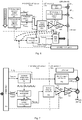
- Figure 6 shows a possible high level LSF encoder analysis structure, for a low complexity quantization of the LSF in target vector, into the indices set ⁇ i L , i H , i submode , i gain , i shapeO / (i shapeA , i shapeB ) ⁇ .
- the L target and H target target vectors are presented to a low rate first stage VQ 610 to obtain two indices: i L an i H .
- the shape quantization is made in a warped/transformed domain 600a, using two spherical unit energy PVQ submodes: an outlier( outl ) submode 601 and a regular( reg ) submode 602, which have different shape resolution properties over different dimensions, but with sufficient similarities so that the regular finer resolution shape search may use the preliminary result of the lower shape resolution outlier submode shape search ( rt outl ) to obtain rt reg .
- These two integer vectors are searched by adding unit pulses, and after all the allowed unit pulses have been found, the integer vectors are normalized to (float) unit energy vectors rt en1,outl and rt en1,reg , which are sent to the submode selector 603.
- the submode selector 603 acts as a switch and forwards either rt en1,outl or rt en1 , reg , as rt en1 to the inverse warping block 604, depending on which submode (given by i submode ) being evaluated by the W(MSE) minimization block.
- the candidate shape vector is warped back to the LSF-residual domain 600b and scaled with a gain g hat given by a gain index i gain , in a gain amplifier 605 (and possibly also by a global gain G_MEAN ST2 in a global gain amplifier 606).
- the shape is searched in the warped LSF-domain, using an efficient PVQ-search.
- the final gain-shape minimization is preferably performed in the LSF-residual domain.
- the global search uses MSE or WMSE minimization to find the best submode and gain combination resulting in a shape rt en1 and the best gain g hat with index i gain .
- the integer vector rt of length N corresponding to the total selected unit energy shape rt en1 is indexed by a PVQ enumeration scheme 607.
- a PVQ enumeration scheme 607 In case of the outlier mode there is only one resulting PVQ-index, i shapeO and in case of the regular mode there are two resulting shape indeces i shapeA and i shapeB .
- the dimension N x and number of unity pulses K x for each shape index is obtained by table lookup based on i submode .
- the set of LSF-indices ⁇ i L , i H , i submode , i gain , i ShapeO / (i shapeA , i shapeB ) ⁇ are forwarded to a ARE/MUX (multiplexing) unit 608 which contains an arithmetic/range encoder (ARE) unit if fractional bits are used, and a regular bit level multiplexing unit if whole integer bits are employed for the set of LSF-indices.
- ARE/MUX (multiplexing) unit 608 which contains an arithmetic/range encoder (ARE) unit if fractional bits are used, and a regular bit level multiplexing unit if whole integer bits are employed for the set of LSF-indices.
- the thick arrow in the figure indicates the LSF indices being sent to the decoder.
- the LSF R2T,en1,dec vector is obtained from the PVQ inverse quantizer using the submode index i submode and the PVQ-indexed shape indices i shapeO , / ⁇ i shapeA, i shapeB ⁇ .
- the adjustment gain hat,dec is obtained from the index i gain
- the LSF R2T,en1,dec vector is warped to the LSF domain, to obtain the LSF R2,en1,dec vector.
- First stage subvectors L iL,dec and H iL,dec are obtained from the stage 1 inverse VQ (codebook lookup), using indices i L and i H .
- Fig. 7 shows an embodiment of a schematic decoder.
- the set of LSF-indices ⁇ i L , i H, i submode, i gain, i sbapeO /( i shapeA, i sbapeB ) ⁇ are obtained (at the thick arrow) from the encoder at an ARD/DEMUX (demultiplexing) unit 701, which contains an arithmetic/range decoder (ARD) unit if fractional bits are used, and a regular bit level de-multiplexing unit if whole integer bits are employed for the set of LSF-indices.
- ARD/DEMUX (demultiplexing) unit 701 contains an arithmetic/range decoder (ARD) unit if fractional bits are used, and a regular bit level de-multiplexing unit if whole integer bits are employed for the set of LSF-indices.
- ARD/DEMUX (demultiplexing) unit 701 contains an arithmetic/range de
- the two stage 1 indices i L , i H are decoded into the N dimensional vector LSF ST1,dec by table lookup 702.
- the decoded shape vector rt en1,dec is warped 706 back from a warped/transformed domain 700a to the LSF-residual domain 700b and scaled 707 with a gain g hat given by a gain index i gain . (and also scaled 708 by the global gain G_MEAN ST2 , if necessary) and stored as LSF ST2,dec . Finally the quantized LSF q,dec vector is obtained by adding LSF mean , LSF ST1,dec and the decoded stage 1 vector to LSF ST2,dec.
- Stage 1 search The stored stage 1 codebooks Lcbk and Hcbk each of size N1*2 3 values, (8 coefficients x N1 vectors per codebook) are searched in each target section L/H by using an MSE search.
- w n may be a fixed vector addressing the human ear's lower sensitivity to high frequencies.
- w n [1 0.968 0.936 0.904 0.872 0.840 0.808 0.776 0.744 0.712 0.680 0.648 0.6160 0.584 0.552 0.520], or one may apply a more advanced weighting like IHM (Inverse Harmonic Mean).
- IHM Inverse Harmonic Mean
- the target stage2 LSF-residual is transformed to the warped domain using e.g. a Matrix operation, e.g. 16 by 16 matrix operation in case of 16 dimensional LSF vector.
- LSF R2T LSF R2 H becomes (forward transform)
- LSF R2T [2 -2 -4 0 -8 0 0 0 -16 0 0 0 0 0 0 0 0]
- LSF R2T LSF R2 D becomes (forward transform)
- LSF R2T [2.0000 -18.3115 0.0000 -2.0075 -0.0000 -0.7016 0 -0.3395 ... 0 -0.1877 0 -0.1071 -0.0000 -0.0560 0.0000 -0.0175]
- the regular submode is a dimensional targeted high resolution mode, with reconstructions points on or close to a global long term average energy shell, given by the global gain 1.0 * G_MEAN ST2 , with energy G_MEAN ST2 2 .
- the regular mode has higher shape resolution than the outlier mode in a subset/section of given dimensions.
- the regular mode may use 2-4 additional gain levels.
- this code space is given to a gain adjustment index of the regular mode near 1.0. e.g. [2- 1/12 , 2 1/12 ] in case of 1 bit and [2 -2/24 2 -1/24 , 2 1/24 , 2 2/24 ] in case of 2 bits.
- These levels are positioned between the neighbouring outlier energy shells, and the selection is made by MSE evaluation of the gain-shape combinations.
- the outlier submode is an all-dimensional lower resolution mode, lower resolution in relation to the regular submode.
- the outlier submode has reconstruction points further away from the global long term average energy shell, given by the global gain 1.0 * G_MEAN ST2 , with energy G _ MEAN ST2 2 .
- the outlier mode has the same shape resolution for all possible energy/gain shells, and it may correct errors equally well in all dimensions.
- Stage 2 shape search One may search each submode shape (the full 16 dimesional outlier section, regular section A, regular section B) using a complete PVQ shape search for that section, however to avoid several PVQ shape -searches for the various submodes in some cases.
- Fig.8 is a flow chart showing an embodiment of a stage 2 shape search flow.
- the stage 2 search may be performed by the following steps:
- the section rearranged vectors rt outl_en1norm,lin , rt regAB_en1norm,lin , rt regA_en1norm,lin are arranged back to the original LSF differential domain coefficient order as rt outl_en1norm , rt regAB_en1norm , rt regA_en1norm , and the corresponding coefficients in vectors rt outl,lin , rt regAB,lin and rt regA,lin are arranged back into integer vectors rt outl , rt regAB and rt regA (step 810).
- the integer vectors rt outl,lin , rt regAB,lin and rt regA,lin are saved to be able to easily enumerate these vectors into indices, using a PVQ-enumeration technique for subsequent transmission, which will be performed after the best available combination of a gain-value and a PVQ shape(s) option has been selected.
- PVQ shape search projection and PVQ fine search equations This part may be seen as a generic description of a PVQ shape search including initial low cost projection and a pulse by pulse fine shape search.
- the PVQ-coding concept was introduced by R. Fischer in the time span 1983-1986 ( Fisher T. R.: "A pyramid vector quantizer", IEEE Transactions on information theory, vol. IT-32, no. 4, July 1986 ) and has evolved to practical use since then with the advent of efficient digital signal processors, DSPs.
- the PVQ encoding concept involves locating/searching and then enumerating a point on the N-dimensional hyper-pyramid with the integer L1-norm of K unit pulses.
- the L1-norm is the sum of the absolute values of the vector, i.e. the absolute sum of the signed integer PVQ vector is restricted to be K , where a unit pulse is represented by an integer value of "1".
- an L1-norm of K for PVQ(N,K) signifies that the absolute sum of all elements in the PVQ-integer vector y(n) has to be K .
- the structured PVQ(N,K) allows for several search optimizations, where the primary optimization is to move the target to the all positive "quadrant" in N -dimensional space and the second optimization is to use an L1-norm projection to the pyramid neighborhood as a starting approximation for y(n), before entering into a fine search to reach K .
- a third optimization is to iteratively update the Q PVQ quotient terms, instead of re-computing Eq. 15 below over the whole vector space N , for every evaluated change to the vector y(n) in pursuit of reaching the L1-norm K , where an exact K is required for the subsequent PVQ-enumeration step.
- Unit energy normalized PVQ-shape search introduction The goal of the PVQ(N,K) shape search procedure is to find the best scaled and unit energy normalized vector x q (n).
- an optional temporary inloop energy value enloop y (k,n) may be used instead of energy y (k,n) (Eq. 17) and thus for energy y in (Eq. 15) however in this description they have the same value.
- Q PVQ k n corr xy k n 2 enloop y k n
- n best n , if Q PVQ k n > Q PVQ k n best
- the iterative maximization of Q PVQ (k,n) may start from a zero number of placed unit pulses or from an adaptive lower cost pre-placement number of unit pulses, based on a projection to a point on or below the K' th-pyramid's surface, with a guaranteed hit or undershoot of unit pulses in the target L1 norm K .
- a low cost projection to the K or K-1 sub pyramid may be made and used as a starting point for y . This will save the number of operations an iterative fine PVQ-search will need to perform to reach K .
- the low cost projection to "K" or slightly lower than K is typically less computationally expensive in DSP cycles than repeating an iterative unit pulse inner loop test (Eq 20) N*K times, however there is a drawback with the low cost projection that it may produce an inexact result due to the use of a non-linear N -dimensional floor application.
- the resulting L1-norm of the low cost projection may typically be anything between " K " to roughly " K-4 ", i.e. the result after the projection usually needs to be fine searched to reach the required target L1-norm of K .
- the final integer shape vector y(n) of dimension N should adhere to the L1 norm of K pulses.
- the fine search starts from a lower point in the pyramid and iteratively finds its way to the surface of the N -dimensional K 'th hyperpyramid.
- the K -value in the fine search can typically range from 1 to 512 unit pulses. I.e. by employing (Eq. 20) until the desired L1-norm of K has been reached.
- the resulting unwarped vectors in the LSF residual domain are called r outl_en1norm, r regAB _ en1norm and r regA _ en1norm.
- r outl_en1norm The resulting unwarped vectors in the LSF residual domain are called r outl_en1norm, r regAB _ en1norm and r regA _ en1norm.
- r t en 1 6.6691 ⁇ 16.4483 5.0226 ⁇ 0.8074 1.6795 ⁇ 0.2607 0.3087 ⁇ 0.2174 ... 0.1582 ⁇ 0.1421 0.0911 ⁇ 0.0823 0.0505 ⁇ 0.0432 0.0235 ⁇ 0.0128 / 344 0.5 ,
- a Weighted MSE determination is made to determine the best quantized stage 2 LSF residual vector g i _ best _ comb * GMEAN ST2 * [ r s t 2, i_best_comb ] among the available scalar gain-factors and the available shape-vector alternatives.
- the allowed gain shape combinations are made up of the allowed gain and shape combinations.
- i submode , i gain and I shape , B are set corresponding to the established i best_comb
- Stage 2 shape and gain determination in the warped LSF residual domain Another complexity-wise attractive alternative to establish g hat and LSF R2 , en1 is to evaluate the possible gain-shape combination in the warped domain as this will then only require one transformation of one single selected best gain-shape combination.
- the drawback is that the weights w n will no longer represent a single frequency point in the LSF-residual domain, for that reason all the weights may be set to 1.0 in a lowest complexity solution.
- the warped domain vector rt st2,i_comb is warped back to the unwarped LSF-residual domain by applying the IRDCT, IDCT or Hadamard, resulting in r st2, i_best_comb .
- the table 6 shows the gain-shape combinations for a warped domain (W)MSE search in the 38 bit example case. Table 6 Available gain shape combinations in the warped LSF-residual domain for the 38 bit example LSF-stage 2 algorithmic VQ.
- the quantized LSF vector is obtained by combining the mean vector, the stage 1 contribution and a scaled unit energy stage 2 contribution.
- LS F q LS F Mean + L iL H iH + g hat * GMEA N ST 2 * LS F R 2 , en 1
- the 16 dimensional integer vector rt regAB,lin or rt regA,lin is enumerated into two PVQ-indices I shape , A . I shape , B . using known PVQ-enumeration techniques, such as the computationally efficient MPVQ-scheme described below, or possibly a variation of Fischer's original enumeration.
- the I shape,B Index is set to 0, and no PVQ enumeration for the second set of coefficients B takes place.
- I shape,A is obtained by PVQ-enumerating the set A coefficients in rt regA,lin .
- the I shape,B index is initially obtained by PVQ-enumerating the set B coefficients in rt regAB,lin . Following this enumeration, an offset of 1 is added to I shape,B to make code space for the all zero B-shape.
- An "all zero" means no shape at all for the set B points, i.e. when zeroed the second set of coefficients B do not have any energy, nor any shape/direction.
- the I shape,A index is obtained by PVQ-enumerating the set A coefficients in rt regAB,lin. ,
- Example PVQ enumeration scheme MPVQ short codeword enumeration of integer vector ZN.K
- the z N , K integer vector with dimension N and an L1- norm of K, where K is K unit pulses, may be enumerated using a method that divides the PVQ shape index into two shorter codewords which are composed as follows:
- N MPVQ N K 1 + 2 ⁇ U N K + N MPVQ N ⁇ 1 , K
- N MPVQ N K 1 + U N K + U N , K + 1
- the bits that are to be transmitted are, in the embodiment, first sent to a multiplexing unit of the encoder where the bits are multiplexed. Thereafter, the multiplexed bits are transmitted over a communication channel to the decoder.
- Stage 1 indices i L and i H . are sent to the multiplexing unit. It is noted that the [ LSF Mean ] vector, i.e. the long term average LSF coefficient vector, is not transmitted, it is stored in a ROM in both the encoder an the decoder.
- the selected submode is the regular submode
- a single bit with value 1 is transmitted to the multiplexing unit. This is for the exemplary embodiment where there are only two submodes to select from: a regular submode and an outlier submode. If there are more than two submodes to select from, a corresponding number of bits are needed.
- the selected submode is the outlier submode
- a single bit with value 0 is transmitted to the multiplexing unit.
- a 1 is transmitted when the outlier submode is selected and a 0 is transmitted when the regular submode is selected. Anyhow, the decoder needs to know in advance the interpretation of a "0" and a "1".
- the fine gain index i gain (see Table 5) corresponding to the determined fine gain g i is sent to the mutiplexing unit. It is noted that the value GMEAN ST2 , i.e. the long term average stage 2 gain, is in this embodiment not transmitted, it is stored in ROM in both encoder an decoder.
- the integer pulse vector ( rt in Fig 7 ) corresponding to the selected best combination have been forwarded to a PVQ-enumeration unit.
- the PVQ enumeration unit may e.g. use the efficient MPVQ enumeration as in [EVS 3GPP TS26.445 v13.0.0 sections 5.3.4.2.7.4 "PVQ short codeword indexing" and 6.2.3.2.6.3 "PVQ sub-vector MPVQ de-indexing"].
- the value of I shape,outl and the size parameter SIZE shape , outl are forwarded to the arithmetic (or range) encoder, for multiplexing into the bit-stream.
- the arithmetic/range encoder may use a uniform Probability Density Function, PDF, to encode the shape index.
- the index I shape,outl . is sent to the multiplex unit and multiplexed using ceil(log2( SIZE shape,outl )) bits, (25 bits in the 38 bit example)
- the values of shape indices I shape , A , I shape,B and the size parameters SIZE shapeA SIZE shapeB are forwarded to the arithmetic(or range) encoder, for multiplexing into the bit-stream.
- the arithmetic/range encoder may use a uniform PDF to encode these shape indices.
- the index I shape , A is sent to the multiplex unit and multiplexed using ceil(log2( SIZE shapeA )) bits, (23 bits in the 38 bit example).
- the index I shape , B is sent to the multiplex unit and multiplexed using ceil(log2( SIZE shapeB )) bits, (4 bits in the 38 bit example).
- Table 8 gives on overview of encoded bits as sent to the multiplexing unit, for the 38 bit example. Table 8 Multiplexing of Stage 1 indices and Stage 2 gain-shape information.
- ENCODER SEARCH SELECTED GAIN-SHAPE COMBINATION INDEX I COMB (NOT TRANSMITTED) Stage 1 Low (5 bits) Stage 1 high (5 bits)
- Stage 2 gain index Stage 2 'PVQ' shape index Combination / shell description 0-3 i L i H 0 i gain (2 bits) I shape,outl (24.8536 fractional bits)
- I shapeB 0 (3.7004 fractional bits)
- the decoder performs a submode index i submode , guided operations of the encoder results, to end up with the quantized LSFs (denoted LSF q ), as the required information for constructing the quantized LSFs has been transmitted from the encoder to the decoder, for example as indices.
- LSF q LS F Mean + L iL H iH + g hat ⁇ GMEA N ST 2 ⁇ LS F R 2 , en 1 , dec
- LSF q is now available in the decoder, for use by the overall decoding process, e.g. to represent the Direct-form AR-coefficients in 1/A(z) in a Linear Predictive time domain decoder or to represent a frequency envelope shape in a frequency domain decoder.
- stage1 and stage 2 scaling operations and transforms in ANSI-C syntax are given.
- the first row column of had_fwd_st2_fl (also with all values equal to +0.25), produces the first coefficient when applying the inverse Hadamard transform.
- the transpose of the Hadamard matrix is the Hadamard matrix itself.
- This Hadamard table can be saved in ROM as 16 16-bit words, as all the values have the same magnitude ".25". The only difference is the signs, which may be represented by a single bit per matrix coefficient.
- the RDCT coefficients were obtained by offline matching the LSF-residual inter-coefficient amplitude correlation to its neighbouring coefficients (e.g ACF(1) analysis of on a large database given that abs( LSF R2 (n)) is 1.0, abs( LSF R2 (n-1)) and abs ( LSF R2 (n+1)) both will approximately have a value of 0.25).
- the RDCT matrix is created by designing a first rotational warping matrix R creating an approximation of these inter-coefficient amplitude correlations, and then combining matrix R with a set of DCT basis vectors into the single RDCT(16x16) matrix named st2_rdct_fwd_fl
- the RDCT scaling factors are stored column wise, and the IRDCT scaling factors stored row wise.
- the values in the first column of rdct_fwd_st2_fl (all positive values [0.115... 0.329]), produces the zeroth RDCT coefficient when applying the RDCT transform as matrix operation.
- the first row column of rdct_fwd_st2_fl produces the first inverse transformed coefficient IRDCT(1) when applying the IRDCT transform as a matrix operation.
- DCT scaling factors are stored column wise
- IDCT scaling factors are stored row wise.
- the first row column of dct_fwd_st2_fl produces the first inverse transformed coefficient IDCT(x) when applying the IDCT transform as a matrix operation.
- G_MEAN ST2 contains experimentally obtained values over a very large database for mean scaling of a 2 nd stage quantized residual vector, given a unit energy scaled PVQ-vector.
- the LSF mean table may be trained off-line or simply use a linear spread of points over the normalized frequency unit circle range [0 ...1.0], where 1.0 corresponds to Fs /2, i.e. half the sampling frequency.
- An example of an LSF mean table ⁇ 0.0604248047f, 0.1060791016f, 0.1582641602f, 0.2119750977f, 0.2736206055f, 0.3338623047f, 0.3935546875f, 0.4495849609f, 0.5078125000f, 0.5642089844f, 0.6213378906f, 0.6777343750f, 0.7379150391f, 0.7984619141f, 0.8619995117f, 0.9247436523f ⁇
- LSF-residual codebooks L and H are typically trained offline on a large data set. ⁇ -0.013, -0.018, -0.018, -0.012, 0.009, 0.029, 0.043, 0.046, -0.008, -0.012, -0.015, -0.018, -0.022, -0.028, -0.031, -0.032, -0.023, -0.036, -0.050, -0.060, -0.062, -0.041, -0.014, 0.001, 0.020, 0.024, 0.026, 0.018, -0.003, -0.023, -0.041, -0.049, 0.048, 0.091, 0.102, 0.099, 0.079, 0.063, 0.051, 0.042, -0.003, 0.001, 0.013, 0.016, 0.007, -0.005, -0.016, -0.023, -0.009, -0.004, 0.014, 0.046,
- FIG. 9 a box plot with the SD (Spectral Distortion) results for a 38 bit VQ realization are shown.
- a box plot shows the statistical distribution of a signal.
- the central mark is the median SD
- the edges of the box are the 25th and 75th percentiles
- the whiskers extend to the most extreme data points not considered outliers
- outliers are plotted individually as x's.
- SD is a standard measure within speech and audio coding showing how close the logarithmic FFT (Fast Fourier Transform) envelope of the quantized LSFs (denoted LSF q ) is to the logarithmic FFT envelope of the un-quantized LSFs ( LSF in ).
- FFT Fast Fourier Transform
- Table 9 shows_complexity estimation for an LSF update rate of 100Hz (every 10 ms) .
- Figure 10 depicts an example of a time domain signal, for which a frequency envelope is to be quantized by the proposed LSF quantizer.
- the example shown is 20 ms of a 16 kHz sampled signal.
- Figure 11 shows 1/A(z) poles and LSF/LSP frequency points for the time signal in Fig. 10.
- Fig. 11 depicts the position of the roots of 1/(Az), where A(z) is the result of a 10th order Linear Prediction analysis of the time signal in fig. 10 .
- the corresponding 10 LSFs that are to be transmitted are positioned on the top half of the unit circle as angles in the radian range 0 to pi, but typically one will use the linearly related frequency notation, where 0 radians corresponds to 0 Hz and pi radians corresponds to Fs/2, where Fs is the sampling frequency for the corresponding time signal.
- Figure 12 shows FFT spectrum of the time signal, the spectral envelope achieved by representing the signal with the 1/A(z) polynomial and the un-quantized LSF lines corresponding to 1/A(z).
- Fig. 12 depicts the spectral positions (along the frequency axis) of the LSFs corresponding to 1/(Az), where A(z) is the result of a 10th order Linear Prediction analysis of the Time signal in fig. 10 .
- A(z) is the result of a 10th order Linear Prediction analysis of the Time signal in fig. 10 .
- For a signal with rather clear spectral peaks one may find that the 10 LSF coefficients that are to be quantized and transmitted to represent the spectral envelope, are located close to the spectral peaks of the signal, and further they appear in pairs close to each other.
- This peak/LSF-coefficient relationship for harmonic signal is often used to determine the LSF-quantizer weights in a speech/audio encoder as the spectral
- Fig. 13 depicts a conceptual 2-D projected view of the shells and submodes of the proposed gain-shape LSF-quantizer, (It is conceptual as the locations of the various reconstruction points are not true Pyramid VQ points).
- It is conceptual as the locations of the various reconstruction points are not true Pyramid VQ points.
- outlier shells dotted circles which have energies which differ from the regular shell.
- Each outlier shell has a reduced number of construction points in comparison to the regular "center" shell, and further each outlier shell does not have any dimensional set restriction to be able to handle all types of LSF-residual signals, in both gain and shape directions (i.e. the outlier set handles all dimensions equally and each energy shell has the same number of code points).
- the search is first performed in the shape-only direction assuming optimal gain with the outlier submode resolution, and when that resolution has been achieved, the shape resolution is extended in the regular resolution set ⁇ A ⁇ dimensions, and possibly reduced in the regular resolution set ⁇ B ⁇ dimensions.
- the total gain-shape error is evaluated for all the available energy shells.
- Fig. 14 shows SD-performance in terms of a boxplot for the combined outlier plus regular shells for various warping schemes.
- Fig. 14 one can identify that there is a clear advantage to warp the LSF-input signal, as the Identity transform (no warping) performs considerably worse than the other schemes, further one can find that the Hadamard performs worse than the DCT and RDCT schemes, and further the RDCT warping has slightly better median SD-performance than the DCT, and a similar SD-outlier distribution.
- Fig. 15 shows SD-performance in terms of a boxplot for the combined outlier plus regular shells for various fully quantized 38 bit warping schemes.
- Fig. 15 one can identify that there is a small cost associated with using the average complexity optimized linear search (an increase SD-spread is seen for third box with linear RDCT search), further one can find that with the gain quantization active the Hadamard warping scheme is now approaching the performance of the other warping scheme in terms of SD performance (in relation to the un-quantized gain results in figure 14 ).
- an efficient low complexity method is provided for quantization of LSF coefficients.
- selection of an outlier sub-mode in a multimode PVQ quantizer enables efficient handling of LSF-residual outliers.
- Outliers have very high or very low energy/gains or an atypical shape.
- selection of a regular sub-mode in a multimode PVQ quantizer enables higher resolution coding of the most frequent/typical LSF-residual shapes.
- the outlier mode employs a non-split VQ while the regular non-outlier submode employs a split-VQ, with different bits/coefficient in each split segment.
- the split segments may preferably be a nonlinear sample of the transformed vector.
- application of an efficient dual(multi)-mode PVQ-search enables a very efficient search and sub-mode selection in a multimode PVQ-based gain-shape structure.
- an encoder 1600 and a decoder 1800 are provided.
- Figs. 16-17 are block diagrams depicting the encoder 1600.
- Figs. 18-19 are block diagrams depicting the decoder 1800.
- the encoder 1600 is configured to perform the methods described for the encoder 1600 in the embodiments described herein, while the decoder 1800 is configured to perform the methods described for the decoder 1800 in the embodiments described herein.
- the embodiments may be implemented through one or more processors 1603 in the encoder depicted in Figs. 16 and 17 , together with computer program code 1605 for performing the functions and/or method actions of the embodiments herein.
- the program code mentioned above may also be provided as a computer program product, for instance in the form of a data carrier carrying computer program code for performing embodiments herein when being loaded into the encoder 1600.
- a data carrier carrying computer program code for performing embodiments herein when being loaded into the encoder 1600.
- One such carrier may be in the form of a CD ROM disc. It is however feasible with other data carriers such as a memory stick.
- the computer program code may furthermore be provided as pure program code on a server and downloaded to the encoder 1600.
- the encoder 1600 may further comprise a communication unit 1602 for wireline or wireless communication with e.g. the decoder 1800.
- the communication unit may be a wireline or wireless receiver and transmitter or a wireline or wireless transceiver.
- the encoder 1600 further comprises a memory 1604.
- the memory 1604 may, for example, be used to store applications or programs to perform the methods herein and/or any information used by such applications or programs.
- the computer program code may be downloaded in the memory 1604.
- An audio encoder 1600 may comprise an apparatus for handling input Line Spectral Frequency, LSF, coefficients (LSF in ), wherein the apparatus is configured to determine LSF residual coefficients (LSF R2 ) as first compressed LSF coefficients subtracted from the input LSF coefficients, and to transform the LSF residual coefficients (LSF R2 ) into a warped domain (LSF R2T ); to apply one of a plurality of gain-shape coding schemes on the transformed LSF residual coefficients in order to achieve gain-shape coded LSF residual coefficients, where the plurality of gain-shape coding schemes have mutually different trade-offs in one or more of gain resolution and shape resolution for one or more of the transformed LSF residual coefficients; and transmit, over a communication channel to a decoder, the first compressed LSF coefficients, the gain-shape coded LSF residual coefficients, and information on the applied gain-shape coding scheme.
- LSF Line Spectral Frequency
- the apparatus my further be configured to quantize the input LSF coefficients using a first number of bits and determine LSF residual coefficients (LSF R2 ) by subtracting the quantized LSF coefficients from the input LSF coefficients, wherein the transmitted first compressed LSF coefficients are the quantized LSF coefficients.
- LSF R2 LSF residual coefficients
- the apparatus my further be configured to selectively apply one of the plurality of gain-shape coding schemes on the transformed LSF residual coefficients.
- the apparatus my further be configured to remove a mean from the input LSF coefficients.
- the apparatus my further be configured to transform the first compressed LSF coefficients into a warped domain.
- the encoder 1600 may according to the embodiment of fig. 17 comprise a determining module 1702 for determining LSF residual coefficients as first compressed LSF coefficients subtracted from the input LSF coefficients, and a transforming module 1704 for transforming the LSF residual coefficients into a warped domain.
- the encoder 1600 may further comprise an applying module for 1706 for applying one of a plurality of gain-shape coding schemes on the transformed LSF residual coefficients in order to achieve gain-shape coded LSF residual coefficients, where the plurality of gain-shape coding schemes have mutually different trade-offs in one or more of gain resolution and shape resolution for one or more of the transformed LSF residual coefficients, and a transmitting module 1708 for transmitting, over a communication channel to a decoder, the first compressed LSF coefficients, the gain-shape coded LSF residual coefficients, and information on the applied gain-shape coding scheme.
- an applying module for 1706 for applying one of a plurality of gain-shape coding schemes on the transformed LSF residual coefficients in order to achieve gain-shape coded LSF residual coefficients, where the plurality of gain-shape coding schemes have mutually different trade-offs in one or more of gain resolution and shape resolution for one or more of the transformed LSF residual coefficients
- the embodiments herein may be implemented through one or more processors 1803 in the decoder 1800 depicted in Figs. 18 and 19 , together with computer program code 1805 for performing the functions and/or method actions of the embodiments herein.
- the program code mentioned above may also be provided as a computer program product, for instance in the form of a data carrier carrying computer program code for performing embodiments herein when being loaded into the decoder 1800.
- a data carrier may be in the form of a CD ROM disc. It is however feasible with other data carriers such as a memory stick.
- the computer program code may furthermore be provided as pure program code on a server and downloaded to the decoder 1800.
- the decoder 1800 may further comprise a communication unit 1802 for wireline or wireless communication with the e.g. the encoder 1600.
- the communication unit may be a wireline or wireless receiver and transmitter or a transceiver.
- the decoder 1800 further comprises a memory 1804.
- the memory 1804 may, for example, be used to store applications or programs to perform the methods herein and/or any information used by such applications or programs.
- the computer program code may be downloaded in the memory 1804.
- An audio decoder 1800 may comprise an apparatus for handling input Line Spectral Frequency, LSF, coefficients (LSF in ), wherein the apparatus is configured to receive, over a communication channel from an encoder (1600), a representation of first compressed LSF coefficients, gain-shape coded LSF residual coefficients, and information on an applied gain-shape coding scheme, applied by the encoder; to apply, one of a plurality of gain-shape decoding schemes on the received gain-shape coded LSF residual coefficients according to the received information on applied gain-shape coding scheme, in order to achieve LSF residual coefficients, where the plurality of gain-shape decoding schemes have mutually different trade-offs in one or more of gain resolution and shape resolution for one or more of the gain-shape coded LSF residual coefficients; to transform the LSF residual coefficients from a warped domain into an LSF original domain, and to determine LSF coefficients as the transformed LSF residual coefficients added with the received first compressed LSF coefficients.
- the apparatus may further be configured to de-quantize the quantized LSF coefficients using a first number of bits corresponding to the number of bits used for quantizing LSF coefficients at a quantizer of the encoder, and to determine the LSF coefficients as the transformed LSF residual coefficients added with the de-quantized LSF coefficients, wherein the received first compressed LSF coefficients are quantized LSF coefficients.
- the apparatus may further be configured to receive, over the communication channel from the encoder, the first number of bits used at a quantizer of the encoder.
- the decoder 1800 may according to the embodiment of fig. 19 comprise a receiving module 1902 for receiving, over a communication channel from an encoder, first compressed LSF coefficients, gain-shape coded LSF residual coefficients, and information on an applied gain-shape coding scheme, applied by the encoder.
- the decoder may further comprise an applying module 1904 for applying one of a plurality of gain-shape decoding schemes on the received gain-shape coded LSF residual coefficients according to the received information on applied gain-shape coding scheme, in order to achieve LSF residual coefficients, where the plurality of gain-shape decoding schemes have mutually different trade-offs in one or more of gain resolution and shape resolution for one or more of the gain-shape coded LSF residual coefficients.
- the decoder may further comprise a transforming module 1906 for transforming the LSF residual coefficients from a warped domain into an LSF original domain, and a determining module 1908 for determining LSF coefficients as the transformed LSF residual coefficients added with the received first compressed LSF coefficients.
- circuits may be implemented using digital logic and/or one or more microcontrollers, microprocessors, or other digital hardware. In some embodiments, several or all of the various functions may be implemented together, such as in a single application-specific integrated circuit (ASIC), or in two or more separate devices with appropriate hardware and/or software interfaces between them.
- ASIC application-specific integrated circuit
Landscapes
- Engineering & Computer Science (AREA)
- Physics & Mathematics (AREA)
- Spectroscopy & Molecular Physics (AREA)
- Computational Linguistics (AREA)
- Signal Processing (AREA)
- Health & Medical Sciences (AREA)
- Audiology, Speech & Language Pathology (AREA)
- Human Computer Interaction (AREA)
- Acoustics & Sound (AREA)
- Multimedia (AREA)
- Compression, Expansion, Code Conversion, And Decoders (AREA)
Claims (16)
- Procédé effectué par un codeur (1600) d'un système de communication (100) permettant de gérer des coefficients de fréquence spectrale de ligne, LSF, d'entrée (LSFin), le procédé comprenant :la détermination (204) des coefficients résiduels LSF (LSFR2) en tant que premiers coefficients LSF compressés soustraits aux coefficients LSF d'entrée ;la transformation (206) des coefficients résiduels LSF (LSFR2) dans un domaine déformé (LSFR2T) ;l'application (208), de l'un d'une pluralité de schémas de codage de gain-forme sur les coefficients résiduels LSF transformés pour obtenir des coefficients résiduels LSF codés de gain-forme, où la pluralité de schémas de codage de gain-forme ont des compromis mutuellement différents dans une ou plusieurs d'une résolution de gain et d'une résolution de forme pour un ou plusieurs des coefficients résiduels LSF transformés ; etla transmission (210), sur un canal de communication, à destination d'un décodeur, d'une représentation des premiers coefficients LSF compressés, des coefficients résiduels LSF codés de gain-forme, et d'informations sur le schéma de codage de gain-forme appliqué.
- Procédé selon la revendication 1, comprenant en outre :
la quantification (202) des coefficients LSF d'entrée en utilisant un premier nombre de bits, et dans lequel la détermination (204) de coefficients résiduels LSF (LSFR2) comprend la soustraction des coefficients LSF quantifiés aux coefficients LSF d'entrée, et les premiers coefficients LSF compressés transmis (210) sont les coefficients LSF quantifiés. - Procédé selon la revendication 1 ou 2, dans lequel l'application (208) de l'un d'une pluralité de schémas de codage de gain-forme sur les coefficients résiduels LSF transformés comprend l'application sélective de l'un de la pluralité de schémas de codage de gain-forme.
- Procédé selon la revendication 3, dans lequel la sélection dans l'application sélective (208) de l'un de la pluralité de schémas de codage de gain-forme est effectuée par une combinaison d'une projection de forme de quantification de vecteur de pyramide, PVQ, et d'une recherche fine de forme pour atteindre un premier point de code de pyramide PVQ sur des dimensions disponibles sur une base par coefficient résiduel LSF.
- Procédé selon la revendication 3, dans lequel la sélection dans l'application sélective (208) de l'un de la pluralité de schémas de codage de gain-forme est effectuée par une combinaison d'une projection de forme de quantification de vecteur de pyramide, PVQ, et d'une recherche fine de forme pour atteindre un premier point de code de pyramide PVQ sur des dimensions disponibles suivie d'une autre recherche fine de forme pour atteindre un deuxième point de code de pyramide PVQ à l'intérieur d'un ensemble restreint de dimensions.
- Procédé selon l'une quelconque des revendications précédentes, dans lequel la pluralité de schémas de codage de gain-forme comprend un schéma de codage régulier de quantification de vecteur de pyramide, PVQ, ayant un premier gain de coefficient approximativement constant à 1,0 et un schéma de codage marginal PVQ ayant un deuxième gain de coefficient qui est sélectionnable entre une première valeur et une deuxième valeur.
- Procédé selon l'une quelconque des revendications précédentes, dans lequel la pluralité de schémas de codage de gain-forme utilise des résolutions binaires mutuellement différentes pour différents sous-ensembles de coefficients résiduels LSF.
- Procédé selon l'une quelconque des revendications précédentes, dans lequel les coefficients LSF d'entrées sont des coefficients LSF supprimés moyens.
- Procédé selon l'une quelconque des revendications précédentes, comprenant en outre :
la transformation des premiers coefficients LSF compressés dans un domaine déformé. - Procédé effectué par un décodeur (1800) d'un système de communication (100) permettant de gérer des coefficients de fréquence spectrale de ligne, LSF, le procédé comprenant :la réception (302), sur un canal de communication, en provenance d'un codeur (1600), d'une représentation de premiers coefficients LSF compressés, de coefficients résiduels LSF codés de gain-forme, et d'informations sur un schéma de codage de gain-forme appliqué par le codeur ;l'application (304), de l'un d'une pluralité de schémas de décodage de gain-forme sur les coefficients résiduels LSF codés de gain-forme reçus en fonction des informations reçues sur un schéma de codage de gain-forme appliqué, pour obtenir des coefficients résiduels LSF, où la pluralité de schémas de décodage de gain-forme ont des compromis mutuellement différents dans une ou plusieurs d'une résolution de gain et d'une résolution de forme pour un ou plusieurs des coefficients résiduels LSF codés de gain-forme ;la transformation (306) des coefficients résiduels LSF d'un domaine déformé dans un domaine d'origine LSF ; etla détermination (308) de coefficients LSF en tant que les coefficients résiduels LSF transformés ajoutés aux premiers coefficients LSF compressés reçus.
- Procédé selon la revendication 10, dans lequel les premiers coefficients LSF compressés reçus sont des coefficients LSF quantifiés, le procédé comprenant en outre la déquantification (307) des coefficients LSF quantifiés en utilisant un premier nombre de bits correspondant au nombre de bits utilisés pour la quantification de coefficients LSF à un quantificateur du codeur, et dans lequel les coefficients LSF sont déterminés (308) en tant que les coefficients résiduels LSF transformés ajoutés aux coefficients LSF déquantifiés.
- Procédé selon la revendication 10 ou 11, comprenant en outre la réception, sur le canal de communication, en provenance du codeur, du premier nombre de bits utilisés à un quantificateur du codeur.
- Procédé selon l'une quelconque des revendications 10 à 12, dans lequel la pluralité de schémas de décodage de gain-forme comprend un schéma de décodage régulier de quantification de vecteur de pyramide, PVQ, ayant un premier gain de coefficient approximativement constant à 1,0 et un schéma de décodage marginal PVQ ayant un deuxième gain de coefficient qui est sélectionnable entre une première valeur et une deuxième valeur.
- Procédé selon l'une quelconque des revendications 10 à 13, dans lequel les coefficients LSF d'entrée sont des coefficients LSF supprimés moyens.
- Codeur configuré pour effectuer le procédé selon au moins l'une des revendications 1 à 9.
- Décodeur configuré pour effectuer le procédé selon au moins l'une des revendications 10 à 14.
Applications Claiming Priority (2)
| Application Number | Priority Date | Filing Date | Title |
|---|---|---|---|
| US201662435173P | 2016-12-16 | 2016-12-16 | |
| PCT/EP2017/080678 WO2018108520A1 (fr) | 2016-12-16 | 2017-11-28 | Procédés, codeur et décodeur de gestion de coefficients de fréquence spectrale de ligne |
Publications (2)
| Publication Number | Publication Date |
|---|---|
| EP3555886A1 EP3555886A1 (fr) | 2019-10-23 |
| EP3555886B1 true EP3555886B1 (fr) | 2020-05-13 |
Family
ID=60654939
Family Applications (1)
| Application Number | Title | Priority Date | Filing Date |
|---|---|---|---|
| EP17811886.5A Active EP3555886B1 (fr) | 2016-12-16 | 2017-11-28 | Procédés, codeur et décodeur de gestion de coefficients de fréquence spectrale de ligne |
Country Status (3)
| Country | Link |
|---|---|
| US (1) | US10991376B2 (fr) |
| EP (1) | EP3555886B1 (fr) |
| WO (1) | WO2018108520A1 (fr) |
Families Citing this family (5)
| Publication number | Priority date | Publication date | Assignee | Title |
|---|---|---|---|---|
| EP3555885B1 (fr) * | 2016-12-16 | 2020-06-24 | Telefonaktiebolaget LM Ericsson (PUBL) | Procédé et codeur de gestion de coefficients de représentation d'enveloppe |
| EP3763063B1 (fr) * | 2018-03-08 | 2021-12-15 | Telefonaktiebolaget Lm Ericsson (Publ) | Procédé et appareil pour gérer des signaux d'antenne en vue d'une transmission entre une unité de base et une unité distante d'un système de station de base |
| US10734006B2 (en) * | 2018-06-01 | 2020-08-04 | Qualcomm Incorporated | Audio coding based on audio pattern recognition |
| CN116580719B (zh) * | 2023-05-09 | 2026-04-07 | 哈尔滨工程大学 | 空时域联合的稀疏驱动自适应线谱增强方法 |
| CN121054009B (zh) * | 2025-11-03 | 2026-02-03 | 马栏山音视频实验室 | 基于神经网络的线谱频率增强方法、装置、设备及介质 |
Family Cites Families (5)
| Publication number | Priority date | Publication date | Assignee | Title |
|---|---|---|---|---|
| JP3557255B2 (ja) | 1994-10-18 | 2004-08-25 | 松下電器産業株式会社 | Lspパラメータ復号化装置及び復号化方法 |
| CA2733453C (fr) * | 2000-11-30 | 2014-10-14 | Panasonic Corporation | Dispositif de quantification vectorielle pour des parametres lpc |
| KR100487719B1 (ko) * | 2003-03-05 | 2005-05-04 | 한국전자통신연구원 | 광대역 음성 부호화를 위한 엘에스에프 계수 벡터 양자화기 |
| FR2884989A1 (fr) * | 2005-04-26 | 2006-10-27 | France Telecom | Procede d'adaptation pour une interoperabilite entre modeles de correlation a court terme de signaux numeriques. |
| US9837094B2 (en) * | 2015-08-18 | 2017-12-05 | Qualcomm Incorporated | Signal re-use during bandwidth transition period |
-
2017
- 2017-11-28 EP EP17811886.5A patent/EP3555886B1/fr active Active
- 2017-11-28 WO PCT/EP2017/080678 patent/WO2018108520A1/fr not_active Ceased
- 2017-11-28 US US16/347,229 patent/US10991376B2/en active Active
Non-Patent Citations (1)
| Title |
|---|
| None * |
Also Published As
| Publication number | Publication date |
|---|---|
| WO2018108520A1 (fr) | 2018-06-21 |
| EP3555886A1 (fr) | 2019-10-23 |
| US20190279651A1 (en) | 2019-09-12 |
| US10991376B2 (en) | 2021-04-27 |
Similar Documents
| Publication | Publication Date | Title |
|---|---|---|
| EP3555886B1 (fr) | Procédés, codeur et décodeur de gestion de coefficients de fréquence spectrale de ligne | |
| US10841584B2 (en) | Method and apparatus for pyramid vector quantization de-indexing of audio/video sample vectors | |
| KR101443170B1 (ko) | 다단계 양자화 방법 및 저장 매체 | |
| US20240395268A1 (en) | Methods, encoder and decoder for handling envelope representation coefficients | |
| US8634783B2 (en) | Communication device with reduced noise speech coding | |
| CN115699169B (zh) | 编码装置、解码装置、编码方法及解码方法 | |
| US20040176951A1 (en) | LSF coefficient vector quantizer for wideband speech coding | |
| US20100274556A1 (en) | Vector quantizer, vector inverse quantizer, and methods therefor | |
| US6917712B2 (en) | Encoding apparatus and decoding apparatus | |
| JPWO2011086900A1 (ja) | 符号化装置および符号化方法 | |
| US8949117B2 (en) | Encoding device, decoding device and methods therefor | |
| Lindén et al. | Channel optimization of predictive VQ for spectrum coding | |
| JPH09127993A (ja) | 音声符号化方法及び音声符号化装置 | |
| JPH09127997A (ja) | 音声符号化方法及び装置 |
Legal Events
| Date | Code | Title | Description |
|---|---|---|---|
| STAA | Information on the status of an ep patent application or granted ep patent |
Free format text: STATUS: UNKNOWN |
|
| STAA | Information on the status of an ep patent application or granted ep patent |
Free format text: STATUS: THE INTERNATIONAL PUBLICATION HAS BEEN MADE |
|
| PUAI | Public reference made under article 153(3) epc to a published international application that has entered the european phase |
Free format text: ORIGINAL CODE: 0009012 |
|
| STAA | Information on the status of an ep patent application or granted ep patent |
Free format text: STATUS: REQUEST FOR EXAMINATION WAS MADE |
|
| 17P | Request for examination filed |
Effective date: 20190618 |
|
| AK | Designated contracting states |
Kind code of ref document: A1 Designated state(s): AL AT BE BG CH CY CZ DE DK EE ES FI FR GB GR HR HU IE IS IT LI LT LU LV MC MK MT NL NO PL PT RO RS SE SI SK SM TR |
|
| AX | Request for extension of the european patent |
Extension state: BA ME |
|
| GRAP | Despatch of communication of intention to grant a patent |
Free format text: ORIGINAL CODE: EPIDOSNIGR1 |
|
| STAA | Information on the status of an ep patent application or granted ep patent |
Free format text: STATUS: GRANT OF PATENT IS INTENDED |
|
| DAV | Request for validation of the european patent (deleted) | ||
| DAX | Request for extension of the european patent (deleted) | ||
| INTG | Intention to grant announced |
Effective date: 20200124 |
|
| GRAS | Grant fee paid |
Free format text: ORIGINAL CODE: EPIDOSNIGR3 |
|
| GRAA | (expected) grant |
Free format text: ORIGINAL CODE: 0009210 |
|
| STAA | Information on the status of an ep patent application or granted ep patent |
Free format text: STATUS: THE PATENT HAS BEEN GRANTED |
|
| AK | Designated contracting states |
Kind code of ref document: B1 Designated state(s): AL AT BE BG CH CY CZ DE DK EE ES FI FR GB GR HR HU IE IS IT LI LT LU LV MC MK MT NL NO PL PT RO RS SE SI SK SM TR |
|
| REG | Reference to a national code |
Ref country code: GB Ref legal event code: FG4D |
|
| REG | Reference to a national code |
Ref country code: CH Ref legal event code: EP |
|
| REG | Reference to a national code |
Ref country code: DE Ref legal event code: R096 Ref document number: 602017016840 Country of ref document: DE |
|
| REG | Reference to a national code |
Ref country code: AT Ref legal event code: REF Ref document number: 1271278 Country of ref document: AT Kind code of ref document: T Effective date: 20200615 |
|
| REG | Reference to a national code |
Ref country code: LT Ref legal event code: MG4D |
|
| REG | Reference to a national code |
Ref country code: NL Ref legal event code: MP Effective date: 20200513 |
|
| PG25 | Lapsed in a contracting state [announced via postgrant information from national office to epo] |
Ref country code: LT Free format text: LAPSE BECAUSE OF FAILURE TO SUBMIT A TRANSLATION OF THE DESCRIPTION OR TO PAY THE FEE WITHIN THE PRESCRIBED TIME-LIMIT Effective date: 20200513 Ref country code: NO Free format text: LAPSE BECAUSE OF FAILURE TO SUBMIT A TRANSLATION OF THE DESCRIPTION OR TO PAY THE FEE WITHIN THE PRESCRIBED TIME-LIMIT Effective date: 20200813 Ref country code: GR Free format text: LAPSE BECAUSE OF FAILURE TO SUBMIT A TRANSLATION OF THE DESCRIPTION OR TO PAY THE FEE WITHIN THE PRESCRIBED TIME-LIMIT Effective date: 20200814 Ref country code: FI Free format text: LAPSE BECAUSE OF FAILURE TO SUBMIT A TRANSLATION OF THE DESCRIPTION OR TO PAY THE FEE WITHIN THE PRESCRIBED TIME-LIMIT Effective date: 20200513 Ref country code: PT Free format text: LAPSE BECAUSE OF FAILURE TO SUBMIT A TRANSLATION OF THE DESCRIPTION OR TO PAY THE FEE WITHIN THE PRESCRIBED TIME-LIMIT Effective date: 20200914 Ref country code: SE Free format text: LAPSE BECAUSE OF FAILURE TO SUBMIT A TRANSLATION OF THE DESCRIPTION OR TO PAY THE FEE WITHIN THE PRESCRIBED TIME-LIMIT Effective date: 20200513 Ref country code: IS Free format text: LAPSE BECAUSE OF FAILURE TO SUBMIT A TRANSLATION OF THE DESCRIPTION OR TO PAY THE FEE WITHIN THE PRESCRIBED TIME-LIMIT Effective date: 20200913 |
|
| PG25 | Lapsed in a contracting state [announced via postgrant information from national office to epo] |
Ref country code: HR Free format text: LAPSE BECAUSE OF FAILURE TO SUBMIT A TRANSLATION OF THE DESCRIPTION OR TO PAY THE FEE WITHIN THE PRESCRIBED TIME-LIMIT Effective date: 20200513 Ref country code: LV Free format text: LAPSE BECAUSE OF FAILURE TO SUBMIT A TRANSLATION OF THE DESCRIPTION OR TO PAY THE FEE WITHIN THE PRESCRIBED TIME-LIMIT Effective date: 20200513 Ref country code: BG Free format text: LAPSE BECAUSE OF FAILURE TO SUBMIT A TRANSLATION OF THE DESCRIPTION OR TO PAY THE FEE WITHIN THE PRESCRIBED TIME-LIMIT Effective date: 20200813 Ref country code: RS Free format text: LAPSE BECAUSE OF FAILURE TO SUBMIT A TRANSLATION OF THE DESCRIPTION OR TO PAY THE FEE WITHIN THE PRESCRIBED TIME-LIMIT Effective date: 20200513 |
|
| REG | Reference to a national code |
Ref country code: AT Ref legal event code: MK05 Ref document number: 1271278 Country of ref document: AT Kind code of ref document: T Effective date: 20200513 |
|
| PG25 | Lapsed in a contracting state [announced via postgrant information from national office to epo] |
Ref country code: AL Free format text: LAPSE BECAUSE OF FAILURE TO SUBMIT A TRANSLATION OF THE DESCRIPTION OR TO PAY THE FEE WITHIN THE PRESCRIBED TIME-LIMIT Effective date: 20200513 Ref country code: NL Free format text: LAPSE BECAUSE OF FAILURE TO SUBMIT A TRANSLATION OF THE DESCRIPTION OR TO PAY THE FEE WITHIN THE PRESCRIBED TIME-LIMIT Effective date: 20200513 |
|
| PG25 | Lapsed in a contracting state [announced via postgrant information from national office to epo] |
Ref country code: IT Free format text: LAPSE BECAUSE OF FAILURE TO SUBMIT A TRANSLATION OF THE DESCRIPTION OR TO PAY THE FEE WITHIN THE PRESCRIBED TIME-LIMIT Effective date: 20200513 Ref country code: SM Free format text: LAPSE BECAUSE OF FAILURE TO SUBMIT A TRANSLATION OF THE DESCRIPTION OR TO PAY THE FEE WITHIN THE PRESCRIBED TIME-LIMIT Effective date: 20200513 Ref country code: EE Free format text: LAPSE BECAUSE OF FAILURE TO SUBMIT A TRANSLATION OF THE DESCRIPTION OR TO PAY THE FEE WITHIN THE PRESCRIBED TIME-LIMIT Effective date: 20200513 Ref country code: CZ Free format text: LAPSE BECAUSE OF FAILURE TO SUBMIT A TRANSLATION OF THE DESCRIPTION OR TO PAY THE FEE WITHIN THE PRESCRIBED TIME-LIMIT Effective date: 20200513 Ref country code: RO Free format text: LAPSE BECAUSE OF FAILURE TO SUBMIT A TRANSLATION OF THE DESCRIPTION OR TO PAY THE FEE WITHIN THE PRESCRIBED TIME-LIMIT Effective date: 20200513 Ref country code: ES Free format text: LAPSE BECAUSE OF FAILURE TO SUBMIT A TRANSLATION OF THE DESCRIPTION OR TO PAY THE FEE WITHIN THE PRESCRIBED TIME-LIMIT Effective date: 20200513 Ref country code: AT Free format text: LAPSE BECAUSE OF FAILURE TO SUBMIT A TRANSLATION OF THE DESCRIPTION OR TO PAY THE FEE WITHIN THE PRESCRIBED TIME-LIMIT Effective date: 20200513 Ref country code: DK Free format text: LAPSE BECAUSE OF FAILURE TO SUBMIT A TRANSLATION OF THE DESCRIPTION OR TO PAY THE FEE WITHIN THE PRESCRIBED TIME-LIMIT Effective date: 20200513 |
|
| REG | Reference to a national code |
Ref country code: DE Ref legal event code: R097 Ref document number: 602017016840 Country of ref document: DE |
|
| PG25 | Lapsed in a contracting state [announced via postgrant information from national office to epo] |
Ref country code: SK Free format text: LAPSE BECAUSE OF FAILURE TO SUBMIT A TRANSLATION OF THE DESCRIPTION OR TO PAY THE FEE WITHIN THE PRESCRIBED TIME-LIMIT Effective date: 20200513 Ref country code: PL Free format text: LAPSE BECAUSE OF FAILURE TO SUBMIT A TRANSLATION OF THE DESCRIPTION OR TO PAY THE FEE WITHIN THE PRESCRIBED TIME-LIMIT Effective date: 20200513 |
|
| PLBE | No opposition filed within time limit |
Free format text: ORIGINAL CODE: 0009261 |
|
| STAA | Information on the status of an ep patent application or granted ep patent |
Free format text: STATUS: NO OPPOSITION FILED WITHIN TIME LIMIT |
|
| 26N | No opposition filed |
Effective date: 20210216 |
|
| PG25 | Lapsed in a contracting state [announced via postgrant information from national office to epo] |
Ref country code: MC Free format text: LAPSE BECAUSE OF FAILURE TO SUBMIT A TRANSLATION OF THE DESCRIPTION OR TO PAY THE FEE WITHIN THE PRESCRIBED TIME-LIMIT Effective date: 20200513 |
|
| REG | Reference to a national code |
Ref country code: CH Ref legal event code: PL |
|
| PG25 | Lapsed in a contracting state [announced via postgrant information from national office to epo] |
Ref country code: LU Free format text: LAPSE BECAUSE OF NON-PAYMENT OF DUE FEES Effective date: 20201128 |
|
| REG | Reference to a national code |
Ref country code: BE Ref legal event code: MM Effective date: 20201130 |
|
| PG25 | Lapsed in a contracting state [announced via postgrant information from national office to epo] |
Ref country code: LI Free format text: LAPSE BECAUSE OF NON-PAYMENT OF DUE FEES Effective date: 20201130 Ref country code: CH Free format text: LAPSE BECAUSE OF NON-PAYMENT OF DUE FEES Effective date: 20201130 |
|
| PG25 | Lapsed in a contracting state [announced via postgrant information from national office to epo] |
Ref country code: IE Free format text: LAPSE BECAUSE OF NON-PAYMENT OF DUE FEES Effective date: 20201128 Ref country code: FR Free format text: LAPSE BECAUSE OF NON-PAYMENT OF DUE FEES Effective date: 20201130 |
|
| PG25 | Lapsed in a contracting state [announced via postgrant information from national office to epo] |
Ref country code: TR Free format text: LAPSE BECAUSE OF FAILURE TO SUBMIT A TRANSLATION OF THE DESCRIPTION OR TO PAY THE FEE WITHIN THE PRESCRIBED TIME-LIMIT Effective date: 20200513 Ref country code: MT Free format text: LAPSE BECAUSE OF FAILURE TO SUBMIT A TRANSLATION OF THE DESCRIPTION OR TO PAY THE FEE WITHIN THE PRESCRIBED TIME-LIMIT Effective date: 20200513 Ref country code: CY Free format text: LAPSE BECAUSE OF FAILURE TO SUBMIT A TRANSLATION OF THE DESCRIPTION OR TO PAY THE FEE WITHIN THE PRESCRIBED TIME-LIMIT Effective date: 20200513 |
|
| PG25 | Lapsed in a contracting state [announced via postgrant information from national office to epo] |
Ref country code: MK Free format text: LAPSE BECAUSE OF FAILURE TO SUBMIT A TRANSLATION OF THE DESCRIPTION OR TO PAY THE FEE WITHIN THE PRESCRIBED TIME-LIMIT Effective date: 20200513 |
|
| PG25 | Lapsed in a contracting state [announced via postgrant information from national office to epo] |
Ref country code: BE Free format text: LAPSE BECAUSE OF NON-PAYMENT OF DUE FEES Effective date: 20201130 |
|
| P01 | Opt-out of the competence of the unified patent court (upc) registered |
Effective date: 20230517 |
|
| PG25 | Lapsed in a contracting state [announced via postgrant information from national office to epo] |
Ref country code: SI Free format text: LAPSE BECAUSE OF FAILURE TO SUBMIT A TRANSLATION OF THE DESCRIPTION OR TO PAY THE FEE WITHIN THE PRESCRIBED TIME-LIMIT Effective date: 20200513 |
|
| PGFP | Annual fee paid to national office [announced via postgrant information from national office to epo] |
Ref country code: DE Payment date: 20251128 Year of fee payment: 9 |
|
| PGFP | Annual fee paid to national office [announced via postgrant information from national office to epo] |
Ref country code: GB Payment date: 20251127 Year of fee payment: 9 |