EP3555963B1 - Elektrisches verbindungselement mit einem kontaktelement und herstellungsverfahren dafür - Google Patents
Elektrisches verbindungselement mit einem kontaktelement und herstellungsverfahren dafür Download PDFInfo
- Publication number
- EP3555963B1 EP3555963B1 EP17822424.2A EP17822424A EP3555963B1 EP 3555963 B1 EP3555963 B1 EP 3555963B1 EP 17822424 A EP17822424 A EP 17822424A EP 3555963 B1 EP3555963 B1 EP 3555963B1
- Authority
- EP
- European Patent Office
- Prior art keywords
- connection element
- electric wire
- contact
- electrical connection
- stripped core
- Prior art date
- Legal status (The legal status is an assumption and is not a legal conclusion. Google has not performed a legal analysis and makes no representation as to the accuracy of the status listed.)
- Active
Links
Images


Classifications
-
- H—ELECTRICITY
- H01—ELECTRIC ELEMENTS
- H01R—ELECTRICALLY-CONDUCTIVE CONNECTIONS; STRUCTURAL ASSOCIATIONS OF A PLURALITY OF MUTUALLY-INSULATED ELECTRICAL CONNECTING ELEMENTS; COUPLING DEVICES; CURRENT COLLECTORS
- H01R4/00—Electrically-conductive connections between two or more conductive members in direct contact, i.e. touching one another; Means for effecting or maintaining such contact; Electrically-conductive connections having two or more spaced connecting locations for conductors and using contact members penetrating insulation
- H01R4/28—Clamped connections, spring connections
- H01R4/48—Clamped connections, spring connections utilising a spring, clip, or other resilient member
-
- H—ELECTRICITY
- H01—ELECTRIC ELEMENTS
- H01R—ELECTRICALLY-CONDUCTIVE CONNECTIONS; STRUCTURAL ASSOCIATIONS OF A PLURALITY OF MUTUALLY-INSULATED ELECTRICAL CONNECTING ELEMENTS; COUPLING DEVICES; CURRENT COLLECTORS
- H01R4/00—Electrically-conductive connections between two or more conductive members in direct contact, i.e. touching one another; Means for effecting or maintaining such contact; Electrically-conductive connections having two or more spaced connecting locations for conductors and using contact members penetrating insulation
- H01R4/58—Electrically-conductive connections between two or more conductive members in direct contact, i.e. touching one another; Means for effecting or maintaining such contact; Electrically-conductive connections having two or more spaced connecting locations for conductors and using contact members penetrating insulation characterised by the form or material of the contacting members
- H01R4/62—Connections between conductors of different materials; Connections between or with aluminium or steel-core aluminium conductors
-
- H—ELECTRICITY
- H01—ELECTRIC ELEMENTS
- H01R—ELECTRICALLY-CONDUCTIVE CONNECTIONS; STRUCTURAL ASSOCIATIONS OF A PLURALITY OF MUTUALLY-INSULATED ELECTRICAL CONNECTING ELEMENTS; COUPLING DEVICES; CURRENT COLLECTORS
- H01R4/00—Electrically-conductive connections between two or more conductive members in direct contact, i.e. touching one another; Means for effecting or maintaining such contact; Electrically-conductive connections having two or more spaced connecting locations for conductors and using contact members penetrating insulation
- H01R4/28—Clamped connections, spring connections
- H01R4/48—Clamped connections, spring connections utilising a spring, clip, or other resilient member
- H01R4/4809—Clamped connections, spring connections utilising a spring, clip, or other resilient member using a leaf spring to bias the conductor toward the busbar
- H01R4/48185—Clamped connections, spring connections utilising a spring, clip, or other resilient member using a leaf spring to bias the conductor toward the busbar adapted for axial insertion of a wire end
- H01R4/4819—Clamped connections, spring connections utilising a spring, clip, or other resilient member using a leaf spring to bias the conductor toward the busbar adapted for axial insertion of a wire end the spring shape allowing insertion of the conductor end when the spring is unbiased
- H01R4/4821—Single-blade spring
-
- H—ELECTRICITY
- H01—ELECTRIC ELEMENTS
- H01R—ELECTRICALLY-CONDUCTIVE CONNECTIONS; STRUCTURAL ASSOCIATIONS OF A PLURALITY OF MUTUALLY-INSULATED ELECTRICAL CONNECTING ELEMENTS; COUPLING DEVICES; CURRENT COLLECTORS
- H01R4/00—Electrically-conductive connections between two or more conductive members in direct contact, i.e. touching one another; Means for effecting or maintaining such contact; Electrically-conductive connections having two or more spaced connecting locations for conductors and using contact members penetrating insulation
- H01R4/28—Clamped connections, spring connections
- H01R4/48—Clamped connections, spring connections utilising a spring, clip, or other resilient member
- H01R4/4809—Clamped connections, spring connections utilising a spring, clip, or other resilient member using a leaf spring to bias the conductor toward the busbar
- H01R4/4846—Busbar details
- H01R4/485—Single busbar common to multiple springs
-
- H—ELECTRICITY
- H01—ELECTRIC ELEMENTS
- H01R—ELECTRICALLY-CONDUCTIVE CONNECTIONS; STRUCTURAL ASSOCIATIONS OF A PLURALITY OF MUTUALLY-INSULATED ELECTRICAL CONNECTING ELEMENTS; COUPLING DEVICES; CURRENT COLLECTORS
- H01R13/00—Details of coupling devices of the kinds covered by groups H01R12/70 or H01R24/00 - H01R33/00
- H01R13/02—Contact members
- H01R13/10—Sockets for co-operation with pins or blades
- H01R13/11—Resilient sockets
- H01R13/111—Resilient sockets co-operating with pins having a circular transverse section
Definitions
- the present invention relates to an electrical connection element according to the preamble of claim 1.
- It also relates to a method used to manufacture such an electrical connection element.
- connection elements are known as described in the introduction, for example for electrical outlets.
- connection element The role of such a connection element is to transport the current between the electrical wires of the electrical network and the electrical plug belonging to an electrical device which is plugged into this connection element.
- the connection element comprises for this purpose a part adapted to receive an electric wire coming from the wall and a reception cell adapted to receive the pin of the electric plug in order to put them in electrical contact.
- connection element One solution for reducing the heating of the connection element is to make the body of the connection element in a material having as low an electrical resistance as possible, this body being entirely covered with a coating limiting the contact resistance. with the bare core of the electric wire. In fact, the heating of the connection element increases with the electrical resistance introduced by the latter into the electrical circuit.
- connection element is linked to various parameters, in particular to the volume resistance of the material (linked to its conductivity) and to the contact resistance between the stripped core of the electric wire and the connection element.
- the body is usually made of raw brass. It is also known to produce the latter entirely in brass coated with materials such as tin, silver or gold. This allows to have a resistance of contact with the stripped core of an electric wire less than the contact resistance between the raw brass and the stripped core of the electric wire. However, the cost of such a coated brass is high.
- connection element An example of a connection element is for example described in the document EP1353407 .
- the present invention proposes a connection element in which the heating during the electrical connection of an electric wire is reduced while limiting the costs.
- an electrical connection element according to claim 1.
- connection element it is possible to limit the heating of the body of this connection element during the passage of electric current by reducing the contact resistance between the stripped core of the electric wire and the body. , while limiting the manufacturing costs of the connection element. This is achieved by means of a contact element made of a material having a contact resistance with the stripped core of the electric wire lower than that of the material in which the rest of the connection element is made and arranged inside the connection element.
- connection element according to the invention are set out in claims 2 to 8.
- At least two contact elements made from the second material are provided and said leaf spring is adapted to press the stripped core of the electric wire against the two contact elements simultaneously.
- the invention also relates to an electrical device according to one of Claims 9 and 10.
- this electrical device constitutes a socket for the electrical connection of said electrical wire and of a connection pin belonging to another electrical device.
- the invention finally relates to a method of manufacturing an electrical connection element as described above, in accordance with one of claims 11 to 13.
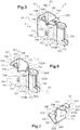
- connection element 1 On the figures 1 to 16 , on the one hand, and 17 to 18, on the other hand, there is shown a two exemplary embodiments of the connection element 1 according to the invention.
- connection element 1 is intended to be integrated into an electrical device, for example into a socket.
- the electrical apparatus according to the invention comprises at least one connection element for the electrical connection of an electrical wire.
- this electrical device constitutes a socket for the electrical connection of said electrical wire and of a connection pin belonging to another electrical device.
- connection element 1 comprises for this purpose a conductive body 100 comprising a housing 110 adapted to receive at least one stripped core 4 of an electric wire 2 ( figure 16 and 18 ) and a cell 120 adapted to receive the connection pin of the electrical plug (not shown) to bring the electrical wire into electrical contact with the connection pin.
- connection element 1 further comprises a leaf spring 200 adapted on the one hand to clamp the electric wire 2 introduced into the housing 110 against a base wall 103 of this housing 110, and on the other hand to tighten the spindle connection inserted into the connection socket 120 ( figures 1 , 5 , 8, 11 , 13, 14 , 15, 16 , 17 and 18 ).
- the electric wire 2 more precisely comprises a stripped core 4 wrapped in an insulating sheath 3 ( figures 16 and 18 ).
- the leaf spring 200 is adapted to press the stripped core 4 stripped of the conductive wire 2 inserted in the housing 110 against the base wall 103 ( figures 16 and 18 ) of this housing 110 and is adapted to press at least one wall of the connection socket 120 against the connection pin, when the latter is introduced into said connection socket 120.
- connection element 1 extends generally along a longitudinal axis X1 orthogonal to a direction of insertion I of the connection pin in the socket 120.
- the direction of insertion I corresponds to the longitudinal axis of the socket. 120 reception ( figures 1 , 5 , 8 , 13 , 14 and 17 ).
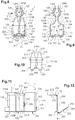
- connection element 1 The body 100 of the connection element 1 is more particularly shown in the figures 1, 2, 4 , 5, 6 , 8, 9, 11 , 13, 14 and 17 .
- the body 100 is made of a first material having a first electrical conductivity satisfactory for conducting the electrical current between the connection pin and the electrical wire 2.
- a conductive metal for example copper or an alloy containing copper.
- the body 100 is here formed of a folded metal strip.
- This body 100 here comprises two lateral wings 101, 102 which extend from the base wall 103, generally along the longitudinal axis X1.
- the base wall 103 is substantially flat and extends perpendicular to the longitudinal axis X1 of the connection element 1 ( figures 8,9 and 17 ).
- Each side wing 101, 102 forms, successively from the base wall 103, a main side wall 111, 112 of the housing 110, an intermediate part 121, 122 curved inwardly of the connection element 1 and a wall curved 123, 124 towards the outside of the connection element, which partially delimits the cell 120 ( figures 1, 2 , 5, 6 , 8, 9 , 13, 14 and 17 ).
- the side walls 111, 112 of the housing 110 are flat and extend at right angles from the base wall 103.
- This base wall 103 then forms a third side wall of the housing 110 ( figures 1, 2, 4 , 5 , 8, 9 and 17 ).
- the housing 110 of the connection element 1 then has a generally parallelepipedal shape delimited by the two main side walls 111, 112, the base wall 103 and said intermediate parts 121, 122 of the side wings 101, 102 ( figures 1, 2 , 5, 6 , 8, 9 , 13, 14 and 17 ).
- This housing 110 is thus practically closed on four sides by said side walls 111, 112, 103 and said intermediate parts 121, 122 of the side wings 101, 102.
- the housing 110 thus constitutes a space for inserting the electric wire into the connection element 100, which here extends in a direction E1 parallel to the direction of insertion I of the connection pin in the socket ( figures 2 , 6 , 9 and 11 ).
- the direction E1 of insertion of the electric wire is therefore here orthogonal to the longitudinal axis X1 of the connection element 1.
- the housing 110 is open along this direction E1.
- the base wall 103 of the housing 110 has a puncture 105, forming two walls 106 which rise from the internal face of this base wall 103, parallel to the side walls 111, 112 of the housing 110 ( figures 5, 6 , 8 9 and 17 ), towards the interior of the housing 110.
- These walls 106 extend longitudinally in the direction E1 of insertion of the electric wire into the housing, over a large part of the height of the housing 110 ( figures 1, 2 , 5, 6 , 8, 9 , 13, 14 and 17 ).
- each wall 106 defines with the side wall 111, 112 of the adjacent housing 110, an insertion corridor 107, 108 ( figure 9 ) of the stripped core 4 of the electric wire 2, which guides the introduction of the stripped core 4 of the electric wire 2 into this housing 110.
- the internal face of the base wall 103 of the body 100 is further provided with a contact element 115 ( figures 8, 9 , 15, 16 , 18 ) made of a second material having a contact resistance with the stripped core of the electric wire less than the contact resistance between the first material and this stripped core of the electric wire, against which said spring blade 200 is adapted to press said stripped core 4 of the conductive wire 2 when the latter is inserted into connection element 1.
- a contact element 115 figures 8, 9 , 15, 16 , 18
- This second material is different from the first material.
- This contact element 115 thus has a limited extent with respect to that of the base wall 103.
- It can have different shapes. It may in particular be in the form of a contact grain or of a pellet, but other shapes are also possible, for example a strip shape.
- the contact element 115 may have a circular shape, with a diameter of between 1 and 2 millimeters, for example equal to 1.5 millimeters. It can also have any other suitable shape, for example with an overall dimension of between 1 and 2 millimeters.
- the corresponding dimensions of the housing are here for example 8 millimeters wide and 11 millimeters high along the insertion direction E1 for the base wall 103, and 7 millimeters long along the longitudinal axis X1.
- the total length of the connection element along this longitudinal axis X1 is here 18 millimeters.
- Each contact element 115 is fixed on the internal face of the base wall 103. In particular, each contact element 115 is fixed in or on the base wall 103.
- the base wall 103 to include a plurality of contact elements 115 against which the leaf spring 200 is suitable for pressing simultaneously or not the stripped core 4 of the electric wire 2.
- Each contact element 115 is adapted to route the electric current from the stripped core of the electric wire in contact with it to the body 100.
- the body 100 is adapted to route the electric current from each contact element 115 to the connection pin plugged into the receiving cell 120.
- connection 1 here more precisely comprises two contact elements 115.
- the contact elements 115 are arranged on the internal face of the base wall 103 such that the leaf spring 200 flattens the stripped core 4 of the electric wire 2 inserted in the housing 110 against at least one of the contact elements. 115.
- each contact element 115 is arranged in one of the insertion corridors 107, 108 delimited between the walls 106 and the side walls 111, 112 adjacent ( figures 8 and 9 ), near the entrance to apartment 110.
- the entrance to the housing 110 corresponds to the open face of the housing 110 located closest to the second end portion 220 of the leaf spring 200, which will be described in more detail later.
- the contact element can be placed in the middle of the passage for inserting the stripped core of the electric wire, or at any point ensuring electrical contact between the contact element and the stripped core of the electric wire.
- a contact element 115 is provided in each of the two insertion passages 107, 108 of the housing 110, and the stripped core 4 of the electric wire 2 is therefore brought into contact with one of the two contact elements 115 which that is the insertion corridor 107, 108 in which it is introduced.
- a plurality of contact elements can be provided in each insertion passage of the housing.
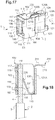
- each insertion passage 107, 108 of the housing 110 two contact elements 115 are provided in each insertion passage 107, 108 of the housing 110. These contact elements are here placed near the entrance and the exit of the housing 110. With the exception of the number d 'contact elements arranged on the internal face of each insertion passage, the connection element according to the second embodiment of the figures 17 and 18 is entirely similar to that of the first exemplary embodiment.
- the stripped core is then pressed against at least one of the two contact elements 115 of the insertion passage 107, 108 in which it is inserted.
- the electric wire is biased in a direction orthogonal to the direction of insertion E1.
- the stripped core 4 of the electric wire can then be placed in the housing in a direction inclined with respect to the direction of insertion E1.
- the presence of two contact elements 115 makes it possible to ensure that the stripped core 4 of the electric wire 2 is in contact with at least one of the two contact elements 115. For example, if the electric wire is pulled from the receiving cell side (to the left on the figure 18 ), the stripped core 4 of the electric wire remains in contact with the contact element 115 arranged near the outlet of the housing 110. If the electric wire is pulled from the side opposite to the receiving cell (to the right on the figure 18 ), the stripped core 4 of the electric wire remains in contact with the contact element 115 arranged near the entrance to the housing 110.
- the contact between the contact element 115 and the stripped core of the electric wire is exerted here on a small area of the stripped core due to the small dimensions of the contact element or elements.
- Said second material preferably contains tin, silver, gold or another precious metal such as palladium, rhodium or platinum.
- copper or tinned brass that is to say copper or raw brass covered with tin, a copper / tin alloy, tin, an alloy of metals including gold, silver or another precious metal such as palladium, rhodium or platinum or a metal such as brass coated with gold, silver or another precious metal such as palladium, rhodium or platinum.
- Copper or brass can be coated with tin, gold, silver for example by a method of electroplating, compacting, co-rolling or co-rolling with solder.
- the contact resistance existing between the second material and the stripped core of the electric wire can be measured by any method known to those skilled in the art.
- the contact resistance can in particular be measured for the application of a low current, of the order for example of 10 to 100 milliAmps, and / or for the application of the nominal current of the connection element 1, for example. between 16 and 20 Amps.
- the contact resistance between the second material and the stripped core of the electric wire and the contact resistance between the first material and the stripped core of the electric wire, measured for the same value of the intensity of the electric current, will preferably be compared.
- the contact resistance can be measured under the operating conditions of the connection element, that is to say in the chemical and mechanical environment of use and after some aging of the connection element.
- the contact resistance between the second material and the stripped core of the electric wire will preferably be compared with the contact resistance between the first material and the stripped core of the electric wire measured for similar operating conditions.
- the contact resistance between the first material and the stripped core of the electric wire is for example measured in a contact element similar to that of the invention, but comprising no contact element.
- This contact resistance depends in particular on the characteristics of hardness, sensitivity to mechanical stresses and resistance to chemical attacks of the material.
- the oxides which may form on the surface of the contact element are cracked when the stripped core of the electrical wire is pressed against this contact element, which reduces the risk of damage. contact resistance between the stripped core of the electric wire and the contact element.
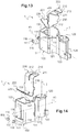
- each contact element 115 belongs to a rivet 117 (see in particular figures 13 to 16 ).
- the base wall 103 is thus equipped with two rivets 117 made from said second conductive material. These are rivets 117 made of pewter.
- Each rivet 117 is riveted to the base wall 103, through an orifice 116 of this base wall 103 ( figure 14 ).
- Each rivet 117 has two ends 115, 118 which project from said base wall 103 ( figures 15, 16 and 18 ).
- the internal end 115 of the rivet 117 then protrudes from the wall 103, towards the interior of the housing 110 ( figures 15, 16 and 18 ), and constitutes the contact element 115.
- This contact element 115 then has for example a thickness projecting from the base wall 103 of between 0.3 and 0.4 millimeters.
- the contact element belongs to a patch attached to said internal face of the base wall of the housing.
- This patch is for example welded to said internal face of the base wall at the point where the internal end 115 of the rivet 117 protrudes in the exemplary embodiment detailed here.
- the two side walls 111, 112 of the housing 110 are extended by the two curved intermediate parts 121, 122 which approach one another, then by the two curved walls 123, 124 which define the cell 120 between them.
- This cell 120 has the overall shape of a cylindrical sleeve, the longitudinal axis of which extends in the direction of insertion I ( figures 1, 2 , 5, 6 and 17 ).
- the intermediate parts 121, 122 of the side wings 101, 102 connect the edges of the main side walls 111, 112 to the arched walls 123, 124 of the cell 120.
- Each intermediate part 121, 122 successively comprises, from the corresponding main side wall 111, 112, a fold 104 towards the inside of the connection element 1, a curved portion 121A, 122A towards the outside, and a portion plane 121B, 122B.
- the two flat portions 121B, 122B extend parallel to one another, close to one another ( figures 2 , 5 and 8 ).
- the fold 104 here has a radius of curvature smaller than that of the arched portion 121A, 122A ( figures 5, 6 and 9 ).
- Each of the flat portions 121B, 122B is extended by one of the arched walls 123, 124 partially forming the cell 120.
- Each arched wall 123, 124 is arched towards the inside of the connection element 1 and has, along of the insertion direction I, one end 123A, 124A which is flared so as to facilitate the insertion of the connection pin in the socket 120 ( figures 1, 2 , 6 , 8, 9 and 17 ).
- the entry of the housing 110 and the flared entry of the cell 120 are arranged on either side of the connection element 1, imposing a direction of insertion of the electric wire and the pin. opposite connection.
- the leaf spring 200 has the shape shown on the figures 3 , 7 , 10 and 12 to 18 .
- the leaf springs 200 of the first and second exemplary embodiments are identical.
- the leaf spring 200 of the connection element 1 is formed in one piece, by a metal strip, a first end portion 210 of which has a longitudinal slot 210A separating two branches 211, 212 adapted to tighten the curved walls 123, 124 of the cell 120 against the connection pin (not shown) and of which a second end part 220 is adapted to clamp the stripped core of the conductive wire inserted in the housing 110 against the base wall 103 and the contact element 115.
- the first end part 210 has a free end 201 and the second end part 220 has a free end 202.
- the leaf spring 200 has, flat, a substantially rectangular outline, slightly tapered at its first free end 201, which extends along a longitudinal direction.
- the leaf spring 200 thus has an overall S-shape ( figure 12 ), with the first and second end parts 210, 220 which extend respectively from one of said bent portions 234, 233 towards one of the free ends 201, 202 of the leaf spring 200 and a central part 230 located between the two angled portions 233, 234.
- the longitudinal slot 210A here extends in the plane of the leaf spring 200, along the first end part 210, of one of the bent portions 234 and, partially, along the central part 230 of the blade. spring 200 ( figures 3 and 10 ).
- Said two front branches 211, 212 of the first end part 210 extend along a mean plane of the leaf spring 200 and are adapted to move away elastically from one another parallel to this mean plane during the '' inserting the connection pin into the connection element 1.
- the second end part 220 of the leaf spring 200 is also separated into two rear branches 221, 222 by another longitudinal slot 240 ( figure 10 ).
- each of the two rear branches 221, 222 further comprises a notch adapted to match the contour of the stripped core 4 of the electric wire 2 introduced into the housing 110 of the body 100 of the connection element 1 ( figures 8 and 10 ).
- the leaf spring 200 is housed in the body 100 such that the second end part 220 and the third central part 230 of the leaf spring 200 are housed in the housing 110 of the body 100 ( figures 1 , 5 , 15.16 and 18 ).
- the central part 230 of the leaf spring 200 is applied against a part of the internal face of each arched portion 121A, 122A of each intermediate part 121, 122 of each side wing 101, 102 of the body 100 of the connection element 1 It then extends substantially parallel to the direction of insertion I of the connection pin into the socket 120.
- the leaf spring 200 has a width substantially equal, with a clearance, to the width of the insertion space formed internally by the housing 110 of the body 100, with the exception of a central zone of the leaf spring 200 which has a greater width because two ears 231, 232 extend locally from the edge of the leaf spring 200 ( figure 3 ).
- the leaf spring 200 in fact comprises means for maintaining in the housing 110, which cooperate in retaining with complementary means of the body 100 of the connection element 1.
- the central part 230 of the leaf spring 200 comprises the two ears 231, 232 which extend in the plane of this central part 230 of the leaf spring 200, towards the outside of the leaf spring ( figures 3 , 7 and 10 ).
- Each of these ears 231, 232 is received in a window 109 of the body 100 of the connection element 1, located here at the level of the fold 104 connecting the arched portion 121A, 122A of the intermediate part 121, 122 of each side wing 101 , 102 to the side wall 111, 112 corresponding to the housing 110 ( figures 1 , 5 and 11 ).
- the leaf spring 200 is thus mounted by snap-fastening into the body 100 of the connection element 1.
- the shape of the ears 231, 232 allows the leaf spring 200 to be held in the housing 110 during the insertion of the stripped core 4 of the electric wire 2.
- the second end part 220 of the leaf spring 200 extends across the housing 110, and the free end 202 of the second end part 220 of the leaf spring 200 bears against the internal face of the wall. base 103 of housing 110 ( figure 7 ) when no conductive wire is inserted into the housing 110.
- the free end 202 of the second end portion 220 of the leaf spring 200 rests against the contact element 115 at rest.
- the leaf spring 200 can be slightly prestressed so that this second end part 220 of the leaf spring 200 permanently exerts pressure against the internal face of the base wall 103 of the housing 110 and / or on the contact element. 115.
- each of the two rear branches 221, 222 of the second end part 220 of the leaf spring 200 is shaped so as to be housed in one of the two insertion passages 107, 108 of the electric wire .
- each rear branch 221, 222 thus extends across one of the insertion corridors 107, 108, between one of the side walls 111, 112 of the housing 110 and the adjacent wall 106, and rests against the base wall 103 and / or the contact element 115 ( figure 15 ) when the stripped core 4 of the electric wire 2 is outside the housing 110 of the connection element 1.
- the leaf spring may be housed at rest in said housing.
- the free end of each rear branch is not necessarily in contact with the base wall and / or the contact element before the introduction of the stripped core of the electric wire.
- the first end portion 210 of the leaf spring 200 emerges out of the housing 110 and extends in the direction of the cell 120 ( figures 11 and 17 ).
- This first end portion 210 of the leaf spring 200 then extends here substantially perpendicular to the direction of insertion I of the connection pin into the socket.
- the first end part 210 of the leaf spring 200 emerges near the end 123A, 124A flared from the arched part 123, 124 of the side wing 101, 102 ( figures 11 and 17 ).
- a part of the body 100 of the connection element 1 extends in the longitudinal slot 210A, between the front branches 211, 212 of the leaf spring 200. This is a part of the flat portion 121B, 122B of the intermediate part 121, 122 of each side wing 101, 102 of the body 100 of the connection element 1.
- each side wing 101, 102 of the body 100 measured according to the direction of insertion I of the connection pin, is lower at the level of the arched portion 121A, 122A of the intermediate part 121, 122 of this wing lateral 101, 102 than at the level of the flat portion 121B, 122B of the intermediate part 121, 122.
- first end portion 210 of the leaf spring 200 This allows the first end portion 210 of the leaf spring 200 to emerge above the edges of the arched portions 121A, 122A of the intermediate portions 121, 122, such that the free ends of the front branches 211, 212 of the first end part 210 of the leaf spring 200 surround the ends of the flat portions 121B, 122B of the intermediate parts 121, 122 of the side wings 101, 102 ( figures 1 and 5 ).
- the leaf spring 200 is thus adapted to cooperate with said wings of the body 100 so as to limit the spacing of the arched parts 123, 124 of the lateral wings 101, 102 delimiting the cell 120.
- the free ends of the front branches 211, 212 of the first end portion 210 of the leaf spring 200 are in contact. with the flat portions 121B, 122B of the intermediate portions 121, 122 of the side wings 101, 102, without exerting pressure on them.
- the free ends of the front branches of the first end part of the leaf spring may be out of the way. contact with the ends of the flat portions of the intermediate portions of the side wings.
- the free ends of the front branches of the first end part of the leaf spring can pinch the ends of the flat portions of the intermediate parts of the side wings.
- the material of the leaf spring has satisfactory rigidity characteristics to play its role of clamping the electric wire and the connection pin. It does not have to be made from a conductive material, which makes it possible to limit the quantity of conductive material used to manufacture the connection element according to the invention.
- the leaf spring is for example made of steel, in particular of stainless steel.
- connection element 1 According to the connection element 1 according to the invention, the heating of the connection element 1 during the passage of electric current from the electric wire to the connection element is limited.
- the second end part 220 of the leaf spring 200 is adapted to flex slightly around the first transverse axis T1 to allow the introduction of this bare core in the corresponding housing 110.
- the second end part 220 bends towards the central part 230 of the leaf spring 200 so as to free a passage for the stripped core 4 of the electric wire in the corresponding insertion passage ( figure 16 ).
- the second end 220 of the leaf spring 200 tends to return to its non-flexed rest position, thus pressing down on the stripped core 4 of the electric wire. 2 against the internal face of the base wall 103 of the housing 110 and against the contact element 115.
- connection element 1 two electric wires can be introduced into each connection element 1, in the two insertion passages 107, 108 of the housing 110 described above.
- each electric wire is inserted in a direction perpendicular to the longitudinal axis X1 of the connection element 1 and parallel to the insertion direction I of the connection pin.
- Each rear branch 221, 222 is adapted to flex independently of the other rear branch, to allow the insertion of the stripped core 4 of the electric wire 2 in one of the insertion passages 107, 108, independently of the insertion of an electric wire in the other insertion corridor.
- the free end 202 of the biased rear branch 221, 222 then exerts pressure on the stripped core of the electric wire, so as to press it against the contact element 115 and the base wall 103 of the housing 110.
- the stripped core 4 of the electric wire 2 is pressed against the contact element 115 made of the second material having a reduced contact resistance compared to the first material which constitutes the rest of the body of the electrical connection element 1. .
- this contact element 115 interposed between the stripped core 4 of the electric wire 2 and the part of the body 100 made of the first material makes it possible to reduce the overall contact resistance existing between the stripped core 4 of the electric wire 2 and the connection element 1 and thus limit the heating of the assembly during the passage of current.
- connection element according to the invention provided with tin rivets is similar to that of a connection element made entirely of tinned brass, without a contact element.
- connection element 115 has a small size compared to the connection element 1 and requires a small amount of second material to be manufactured. Its installation in the connection element is simple. The connection element 1 according to the invention is therefore inexpensive.
- connection element according to the invention is also limited, because the cutting waste of the material forming the body of the connection element (copper or brass for example) can be easily recycled and are therefore resold at a price close to the purchase price.
- the body is made entirely of tin-plated brass for example, not only does this material cost more to purchase, but it is also more difficult to recycle because the tin must be separated from the brass.
- the cutting waste is then resold at a price much lower than the purchase price.
- the connection element according to the invention is therefore economical to produce.
- connection element the Electrical conduction and clamping functions of the connection pin and the electrical wire are decoupled.
- connection pin tends to move the arched parts 123, 124 of the side wings 101, 102 away from each other.
- the spacing of the flat portions 121B, 122B of the intermediate parts 121, 122 of the lateral wings 101, 102 is for its part strongly limited by the action of the leaf spring 200 on these flat portions 121B, 122B of the intermediate parts 121, 122 of the side wings 101, 102.
- this spacing tends to separate the front branches 211, 212 of the leaf spring 200 in the plane of the leaf spring 200.
- the leaf spring 200 is then urged in a transverse direction.
- the leaf spring 200 has low elasticity in this transverse direction, and only allows a small separation of the flat portions 121B, 122B of the intermediate portions 121, 122 of the side wings 101, 102.
- the leaf spring 200 thus cooperates with said wings of the body 100; 300 so as to oppose the spacing of the arched parts 123, 124 4 of the side wings 101, 102 delimiting the cell 120.
- the leaf springs 200; 400 cooperates with said wings of the body 100 to bring the arched parts 123, 124 of the lateral wings 101, 102 towards one another closer to the other.
- the front branches 211, 212 of the leaf spring 200 recall the flat portions 121B, 122B of the intermediate parts 121, 122 of the side wings 101, 102 towards each other, and with them, the arched parts 123, 124 of the 'cell, so as to bring said curved parts 123, 124 closer to one another.
- the front branches 211, 212 of the leaf spring 200 ensure the clamping of the connection pin against the arched parts 123, 124 of the cell.
- connection element according to the invention as described above can be produced in different ways.
- the body 100 is manufactured by folding back a metal strip of the first conductive material, for example raw brass.
- the windows 109 are drilled in the side wings 101, 102 as well as the puncture 105 and the orifices 116 in the base wall 103. This is preferably done before the folding of the metal strip.
- connection element 1 It is then possible to introduce into each orifice 116 a rivet 117 and fix it, then, finally, bend the strip. This is in particular the case during an automated assembly of the connection element 1.
- Rivet 117 may be preformed or formed from a wire or profile of the second material directly into the connection member.
- a pre-tinned wire with a square section of 1 millimeter side and 1.5 millimeter long is used, crimped into the connection element.
- two pellets made from the second material are welded on the internal face of said base wall 103. This is preferably done before the folding of the metal strip.
- connection element having a single insertion corridor delimited by the housing, into which a single electric wire can be inserted.
- this single corridor one or more contact elements are provided according to the invention.
- connection element may also be a connection element of different geometry, for example in which the space for inserting the electrical wire (s) into the housing extends in a direction perpendicular to the direction of insertion of the pin. in the cell.
- the leaf spring may have a different shape.
- connection element can also be a simpler connection element, comprising only a housing and a leaf spring, such as an automatic terminal, without a socket for receiving a connection pin.
- connection elements and their shape can obviously vary.
Landscapes
- Connections Effected By Soldering, Adhesion, Or Permanent Deformation (AREA)
- Connector Housings Or Holding Contact Members (AREA)
- Details Of Connecting Devices For Male And Female Coupling (AREA)
Claims (13)
- Elektrisches Verbindungselement (1) mit einem metallenen leitenden Körper (100), der aus einem ersten Material gefertigt ist und eine Blattfeder (200) aufnimmt, wobei die Blattfeder (200) dazu ausgelegt ist, die abisolierte Seele (4) eines in das Verbindungselement (1) eingeführten leitenden Drahts (2) gegen die Innenseite einer Wandung (103) des Körpers (100) zu drücken, dadurch gekennzeichnet, daß die Innenseite der Wandung (103) des Körpers (100) mit einem aus einem zweiten, vom ersten Material verschiedenen Material gefertigten Kontaktelement (115) versehen ist, gegen das die Blattfeder (200) die abisolierte Seele (4) des leitenden Drahts (2) drücken soll, wenn diese in das Verbindungselement (1) eingeführt ist, wobei das zweite Material einen geringeren Kontaktwiderstand zur abisolierten Seele des elektrischen Drahts aufweist als den Kontaktwiderstand zwischen dem ersten Material und der abisolierten Seele des elektrischen Drahts.
- Elektrisches Verbindungselement (1) gemäß Anspruch 1, bei dem das zweite Material Zinn, Silber oder Gold enthält.
- Elektrisches Verbindungselement (1) gemäß einem der Ansprüche 1 und 2, bei dem das erste Material Kupfer enthält.
- Elektrisches Verbindungselement (1) gemäß einem der vorangehenden Ansprüche, bei dem wenigstens zwei aus dem zweiten Material hergestellte Kontaktelemente vorgesehen sind und die Blattfeder (200) dazu ausgelegt ist, die abisolierte Seele (4) des elektrischen Drahts (2) gegen wenigstens eins der beiden Kontaktelemente zu drücken.
- Elektrisches Verbindungselement (1) gemäß einem der Ansprüche 1 bis 4, bei dem sich jedes Kontaktelement (115) in Bezug auf die Innenseite der Wandung zum Inneren des Körpers (100) hin hervorstehend erstreckt.
- Elektrisches Verbindungselement (1) gemäß einem der Ansprüche 1 bis 5, bei dem jedes Kontaktelement (115) zu einer durch die Wandung (103) hindurch angebrachten Niete (117) gehört.
- Elektrisches Verbindungselement (1) gemäß einem der Ansprüche 1 bis 5, bei dem jedes Kontaktelement zu einer auf der Innenseite der Wandung angebrachten Pastille gehört.
- Elektrisches Verbindungselement (1) gemäß einem der Ansprüche 1 bis 7, bei dem der Körper 100) wenigstens zwei Einführkanäle (107, 108) aufweist, die dazu ausgelegt sind, das Einführen der abisolierten Seele (4) des elektrischen Drahts (2) in das Verbindungselement (2) zu leiten, wobei jeder der Einführkanäle (107, 108) wenigstens teilweise durch die Innenseite der Wandung (103) des Körpers begrenzt ist und wenigstens ein Kontaktelement (115) in jedem Einführkanal (107, 108) angeordnet ist.
- Elektrisches Gerät mit einem Verbindungselement (1) gemäß einem der vorangehenden Ansprüche für die elektrische Verbindung eines elektrischen Drahts.
- Elektrisches Gerät mit einem Verbindungselement (1) gemäß dem vorangehenden Anspruch, das eine Steckdose für eine elektrische Verbindung des elektrischen Drahts mit einem zu einem anderen elektrischen Gerät gehörenden Anschlußstecker bildet.
- Verfahren zum Herstellen eines elektrischen Verbindungselements (1) gemäß einem der Ansprüche 1 bis 8, das einen aus einem ersten Material gefertigten und eine Blattfeder (200) aufnehmenden metallenen leitenden Körper (100) aufweist, wobei die Blattfeder (200) dazu ausgelegt ist, die abisolierte Seele (4) eines in das Verbindungselement (1) eingeführten leitenden Drahts (2) gegen eine Innenseite einer Wandung (103) des Körpers (100) zu drücken, wobei die Innenseite der Wandung (103) des Körpers (100) mit einem aus einem zweiten Material gefertigten Kontaktelement (115) versehen ist,, das einen geringeren Kontaktwiderstand zur abisolierten Seele des elektrischen Drahts als den Kontaktwiderstand zwischen dem ersten Material und der abisolierten Seele des elektrischen Drahts aufweist, gemäß dem der Körper (100) aus dem ersten Material ausgeschnitten wird, dann das aus dem zweiten Material gefertigte Kontaktelement (115) auf der Innenseite der Wandung (103) des Körpers (100) befestigt wird.
- Herstellungsverfahren gemäß dem vorangehenden Anspruch, gemäß dem das Kontaktelement (115) so geformt wird, daß es zu einer Niete (117) gehört, und ein Loch (116) in die Wandung (103) des Körpers (100) gebohrt wird und dort die aus dem zweiten Material gefertigte Niete (117) befestigt wird.
- Herstellungsverfahren gemäß Anspruch 11, gemäß dem das Kontaktelement (115) so geformt wird, daß es zu einer Pastille gehört, und die aus dem zweiten Material gefertigte Pastille auf eine Innenseite der Wandung gelötet wird.
Applications Claiming Priority (2)
| Application Number | Priority Date | Filing Date | Title |
|---|---|---|---|
| FR1662557A FR3060873B1 (fr) | 2016-12-15 | 2016-12-15 | Element de connexion electrique muni d’un element de contact |
| PCT/FR2017/053575 WO2018109402A1 (fr) | 2016-12-15 | 2017-12-14 | Element de connexion electrique muni d'un element de contact |
Publications (2)
| Publication Number | Publication Date |
|---|---|
| EP3555963A1 EP3555963A1 (de) | 2019-10-23 |
| EP3555963B1 true EP3555963B1 (de) | 2021-10-06 |
Family
ID=58455183
Family Applications (1)
| Application Number | Title | Priority Date | Filing Date |
|---|---|---|---|
| EP17822424.2A Active EP3555963B1 (de) | 2016-12-15 | 2017-12-14 | Elektrisches verbindungselement mit einem kontaktelement und herstellungsverfahren dafür |
Country Status (6)
| Country | Link |
|---|---|
| EP (1) | EP3555963B1 (de) |
| CN (1) | CN110088982B (de) |
| ES (1) | ES2902205T3 (de) |
| FR (1) | FR3060873B1 (de) |
| RU (1) | RU2747849C2 (de) |
| WO (1) | WO2018109402A1 (de) |
Families Citing this family (2)
| Publication number | Priority date | Publication date | Assignee | Title |
|---|---|---|---|---|
| FR3126067B1 (fr) | 2021-08-04 | 2023-12-15 | Legrand France | Borne femelle de connexion électrique pour prise de courant, mécanisme de prise de courant et prise de courant associés |
| CN114204287B (zh) * | 2021-12-21 | 2022-11-15 | 山东特瑞电力器材有限公司 | 一种防断裂铜铝设备线夹 |
Citations (2)
| Publication number | Priority date | Publication date | Assignee | Title |
|---|---|---|---|---|
| US20110076900A1 (en) * | 2009-09-29 | 2011-03-31 | Keswani Sushil N | One-piece conductive clip for push-in wire connector |
| DE202013001487U1 (de) * | 2013-02-18 | 2013-03-11 | Phoenix Contact Gmbh & Co. Kg | Stoßstromoptimierte Federklemme |
Family Cites Families (11)
| Publication number | Priority date | Publication date | Assignee | Title |
|---|---|---|---|---|
| FR2748352B1 (fr) * | 1996-05-03 | 1998-07-17 | Arnould App Electr | Socle de branchement pour reseau de transmission, en particulier pour reseau telephonique ou informatique |
| FR2769410B1 (fr) * | 1997-10-06 | 2000-03-31 | Legrand Sa | Bloc de contact pour socle de prise de courant |
| ATE496406T1 (de) * | 2002-04-12 | 2011-02-15 | Weidmueller Interface | Anschlussvorrichtung für leiter |
| CN2881998Y (zh) * | 2006-01-06 | 2007-03-21 | 郑松存 | 铜铝并沟线夹 |
| US7267571B1 (en) * | 2006-11-03 | 2007-09-11 | 3M Innovative Properties Company | Double wall connector |
| FR2936367B1 (fr) * | 2008-09-22 | 2013-01-18 | Integration Tech Et Cablage Itec | Connecteur electrique |
| DE202009013335U1 (de) * | 2009-07-21 | 2010-12-02 | Weidmüller Interface GmbH & Co. KG | Anschlussvorrichtung und Rangierklemme |
| CN102832467B (zh) * | 2012-08-21 | 2015-05-13 | 江门市创艺电器有限公司 | 一种导线连接器 |
| DE102013101410A1 (de) * | 2013-02-13 | 2014-08-14 | Wago Verwaltungsgesellschaft Mbh | Federkraftklemmanschluss und Leiteranschlussklemme |
| DE202013105944U1 (de) * | 2013-12-26 | 2014-01-22 | Wago Verwaltungsgesellschaft Mbh | Federkraft-Klemmanschluss und Steckverbinder hiermit |
| DE202015008280U1 (de) * | 2015-12-01 | 2015-12-14 | Switchlab (Shanghai) Co., Ltd. | Verbesserter Aufbau einer elektrischen Anschlussklemme mit Pfad |
-
2016
- 2016-12-15 FR FR1662557A patent/FR3060873B1/fr not_active Expired - Fee Related
-
2017
- 2017-12-14 RU RU2019116288A patent/RU2747849C2/ru active
- 2017-12-14 CN CN201780077749.8A patent/CN110088982B/zh active Active
- 2017-12-14 ES ES17822424T patent/ES2902205T3/es active Active
- 2017-12-14 WO PCT/FR2017/053575 patent/WO2018109402A1/fr not_active Ceased
- 2017-12-14 EP EP17822424.2A patent/EP3555963B1/de active Active
Patent Citations (2)
| Publication number | Priority date | Publication date | Assignee | Title |
|---|---|---|---|---|
| US20110076900A1 (en) * | 2009-09-29 | 2011-03-31 | Keswani Sushil N | One-piece conductive clip for push-in wire connector |
| DE202013001487U1 (de) * | 2013-02-18 | 2013-03-11 | Phoenix Contact Gmbh & Co. Kg | Stoßstromoptimierte Federklemme |
Also Published As
| Publication number | Publication date |
|---|---|
| EP3555963A1 (de) | 2019-10-23 |
| BR112019010810A2 (pt) | 2019-10-01 |
| FR3060873B1 (fr) | 2020-08-14 |
| CN110088982A (zh) | 2019-08-02 |
| RU2747849C2 (ru) | 2021-05-17 |
| WO2018109402A1 (fr) | 2018-06-21 |
| RU2019116288A (ru) | 2020-11-27 |
| ES2902205T3 (es) | 2022-03-25 |
| CN110088982B (zh) | 2021-06-01 |
| FR3060873A1 (fr) | 2018-06-22 |
| RU2019116288A3 (de) | 2020-11-27 |
Similar Documents
| Publication | Publication Date | Title |
|---|---|---|
| EP3496213B1 (de) | Impedanzanpassungsteil für steckverbinder, der auf einem kabel mit isolierten elektrischen drähten montiert ist | |
| EP2195886B1 (de) | Kontaktclip | |
| EP3555963B1 (de) | Elektrisches verbindungselement mit einem kontaktelement und herstellungsverfahren dafür | |
| EP3227966B1 (de) | Elektrisches verbindungselement, das einen stromdrahtisolierungsmantel penetriert | |
| CH631293A5 (fr) | Contact electrique. | |
| FR2990570A1 (fr) | Embout de branchement pour cable d'alimentation electrique isole et procede de fabrication de cet embout de branchement | |
| EP3336967B1 (de) | Elektrisches anschlusselement | |
| EP1928058B1 (de) | Automatische elektrische Verbindungsklemme | |
| EP2850697B1 (de) | Verbinder für abgeschirmtes stromkabel und entsprechendes montageverfahren | |
| FR3028356A1 (fr) | Borne de connexion electrique a vis imperdable | |
| EP0786159B1 (de) | Elektrische anschlussklemme mit verspannfechern | |
| FR2835974A1 (fr) | Dispositif de connexion a deplacement d'isolant | |
| EP2843766B1 (de) | Elektrische Vorrichtung, die einen gedruckten elektrischen Schaltkreis auf einer Halterungsplatte und eine elektrische Anschlussklemme umfasst | |
| EP3633690A1 (de) | Mehradriges stromkabel | |
| EP0753898A1 (de) | Verbindungsanordnung, sein Herstellverfahren, und elektrische Vorrichtung mit einem solchen Verbindungsanordnung | |
| EP4131659B1 (de) | Steckdosenmechanismus und entsprechende steckdose | |
| FR3060215A1 (fr) | Element de connexion electrique a percage de gaine isolante d’un fil electrique | |
| FR3086808A1 (fr) | Connecteur | |
| FR2968138A1 (fr) | Ensemble de liaison electrique forme par un cable electrique haute tension et un dispositif de connexion | |
| EP0268502B1 (de) | Klammerförmiges Kabelendstück für Zündverteilerdeckel | |
| FR2732516A1 (fr) | Fiche de connexion pour cable coaxial | |
| WO2023011946A1 (fr) | Borne de connexion automatique comprenant deux zones de contact et mécanisme d'appareillage électrique associé | |
| FR3000619A1 (fr) | Organe de raccordement de conducteurs sur une borne unique | |
| FR2917245A1 (fr) | Dispositif de raccordement entre un fil electrique ecrante et un fil de terre. | |
| FR2999347A1 (fr) | Connecteur type rj45 perfectionne |
Legal Events
| Date | Code | Title | Description |
|---|---|---|---|
| STAA | Information on the status of an ep patent application or granted ep patent |
Free format text: STATUS: UNKNOWN |
|
| STAA | Information on the status of an ep patent application or granted ep patent |
Free format text: STATUS: THE INTERNATIONAL PUBLICATION HAS BEEN MADE |
|
| PUAI | Public reference made under article 153(3) epc to a published international application that has entered the european phase |
Free format text: ORIGINAL CODE: 0009012 |
|
| STAA | Information on the status of an ep patent application or granted ep patent |
Free format text: STATUS: REQUEST FOR EXAMINATION WAS MADE |
|
| 17P | Request for examination filed |
Effective date: 20190628 |
|
| AK | Designated contracting states |
Kind code of ref document: A1 Designated state(s): AL AT BE BG CH CY CZ DE DK EE ES FI FR GB GR HR HU IE IS IT LI LT LU LV MC MK MT NL NO PL PT RO RS SE SI SK SM TR |
|
| AX | Request for extension of the european patent |
Extension state: BA ME |
|
| DAV | Request for validation of the european patent (deleted) | ||
| DAX | Request for extension of the european patent (deleted) | ||
| STAA | Information on the status of an ep patent application or granted ep patent |
Free format text: STATUS: EXAMINATION IS IN PROGRESS |
|
| 17Q | First examination report despatched |
Effective date: 20200713 |
|
| GRAP | Despatch of communication of intention to grant a patent |
Free format text: ORIGINAL CODE: EPIDOSNIGR1 |
|
| STAA | Information on the status of an ep patent application or granted ep patent |
Free format text: STATUS: GRANT OF PATENT IS INTENDED |
|
| INTG | Intention to grant announced |
Effective date: 20210507 |
|
| GRAS | Grant fee paid |
Free format text: ORIGINAL CODE: EPIDOSNIGR3 |
|
| GRAA | (expected) grant |
Free format text: ORIGINAL CODE: 0009210 |
|
| STAA | Information on the status of an ep patent application or granted ep patent |
Free format text: STATUS: THE PATENT HAS BEEN GRANTED |
|
| AK | Designated contracting states |
Kind code of ref document: B1 Designated state(s): AL AT BE BG CH CY CZ DE DK EE ES FI FR GB GR HR HU IE IS IT LI LT LU LV MC MK MT NL NO PL PT RO RS SE SI SK SM TR |
|
| REG | Reference to a national code |
Ref country code: GB Ref legal event code: FG4D Free format text: NOT ENGLISH |
|
| REG | Reference to a national code |
Ref country code: CH Ref legal event code: EP Ref country code: AT Ref legal event code: REF Ref document number: 1437004 Country of ref document: AT Kind code of ref document: T Effective date: 20211015 |
|
| REG | Reference to a national code |
Ref country code: IE Ref legal event code: FG4D Free format text: LANGUAGE OF EP DOCUMENT: FRENCH |
|
| REG | Reference to a national code |
Ref country code: DE Ref legal event code: R096 Ref document number: 602017047257 Country of ref document: DE |
|
| REG | Reference to a national code |
Ref country code: LT Ref legal event code: MG9D |
|
| REG | Reference to a national code |
Ref country code: NL Ref legal event code: MP Effective date: 20211006 |
|
| REG | Reference to a national code |
Ref country code: AT Ref legal event code: MK05 Ref document number: 1437004 Country of ref document: AT Kind code of ref document: T Effective date: 20211006 |
|
| REG | Reference to a national code |
Ref country code: ES Ref legal event code: FG2A Ref document number: 2902205 Country of ref document: ES Kind code of ref document: T3 Effective date: 20220325 |
|
| PG25 | Lapsed in a contracting state [announced via postgrant information from national office to epo] |
Ref country code: RS Free format text: LAPSE BECAUSE OF FAILURE TO SUBMIT A TRANSLATION OF THE DESCRIPTION OR TO PAY THE FEE WITHIN THE PRESCRIBED TIME-LIMIT Effective date: 20211006 Ref country code: LT Free format text: LAPSE BECAUSE OF FAILURE TO SUBMIT A TRANSLATION OF THE DESCRIPTION OR TO PAY THE FEE WITHIN THE PRESCRIBED TIME-LIMIT Effective date: 20211006 Ref country code: FI Free format text: LAPSE BECAUSE OF FAILURE TO SUBMIT A TRANSLATION OF THE DESCRIPTION OR TO PAY THE FEE WITHIN THE PRESCRIBED TIME-LIMIT Effective date: 20211006 Ref country code: BG Free format text: LAPSE BECAUSE OF FAILURE TO SUBMIT A TRANSLATION OF THE DESCRIPTION OR TO PAY THE FEE WITHIN THE PRESCRIBED TIME-LIMIT Effective date: 20220106 Ref country code: AT Free format text: LAPSE BECAUSE OF FAILURE TO SUBMIT A TRANSLATION OF THE DESCRIPTION OR TO PAY THE FEE WITHIN THE PRESCRIBED TIME-LIMIT Effective date: 20211006 |
|
| PG25 | Lapsed in a contracting state [announced via postgrant information from national office to epo] |
Ref country code: IS Free format text: LAPSE BECAUSE OF FAILURE TO SUBMIT A TRANSLATION OF THE DESCRIPTION OR TO PAY THE FEE WITHIN THE PRESCRIBED TIME-LIMIT Effective date: 20220206 Ref country code: SE Free format text: LAPSE BECAUSE OF FAILURE TO SUBMIT A TRANSLATION OF THE DESCRIPTION OR TO PAY THE FEE WITHIN THE PRESCRIBED TIME-LIMIT Effective date: 20211006 Ref country code: PT Free format text: LAPSE BECAUSE OF FAILURE TO SUBMIT A TRANSLATION OF THE DESCRIPTION OR TO PAY THE FEE WITHIN THE PRESCRIBED TIME-LIMIT Effective date: 20220207 Ref country code: PL Free format text: LAPSE BECAUSE OF FAILURE TO SUBMIT A TRANSLATION OF THE DESCRIPTION OR TO PAY THE FEE WITHIN THE PRESCRIBED TIME-LIMIT Effective date: 20211006 Ref country code: NO Free format text: LAPSE BECAUSE OF FAILURE TO SUBMIT A TRANSLATION OF THE DESCRIPTION OR TO PAY THE FEE WITHIN THE PRESCRIBED TIME-LIMIT Effective date: 20220106 Ref country code: NL Free format text: LAPSE BECAUSE OF FAILURE TO SUBMIT A TRANSLATION OF THE DESCRIPTION OR TO PAY THE FEE WITHIN THE PRESCRIBED TIME-LIMIT Effective date: 20211006 Ref country code: LV Free format text: LAPSE BECAUSE OF FAILURE TO SUBMIT A TRANSLATION OF THE DESCRIPTION OR TO PAY THE FEE WITHIN THE PRESCRIBED TIME-LIMIT Effective date: 20211006 Ref country code: HR Free format text: LAPSE BECAUSE OF FAILURE TO SUBMIT A TRANSLATION OF THE DESCRIPTION OR TO PAY THE FEE WITHIN THE PRESCRIBED TIME-LIMIT Effective date: 20211006 Ref country code: GR Free format text: LAPSE BECAUSE OF FAILURE TO SUBMIT A TRANSLATION OF THE DESCRIPTION OR TO PAY THE FEE WITHIN THE PRESCRIBED TIME-LIMIT Effective date: 20220107 |
|
| REG | Reference to a national code |
Ref country code: DE Ref legal event code: R097 Ref document number: 602017047257 Country of ref document: DE |
|
| PG25 | Lapsed in a contracting state [announced via postgrant information from national office to epo] |
Ref country code: SM Free format text: LAPSE BECAUSE OF FAILURE TO SUBMIT A TRANSLATION OF THE DESCRIPTION OR TO PAY THE FEE WITHIN THE PRESCRIBED TIME-LIMIT Effective date: 20211006 Ref country code: SK Free format text: LAPSE BECAUSE OF FAILURE TO SUBMIT A TRANSLATION OF THE DESCRIPTION OR TO PAY THE FEE WITHIN THE PRESCRIBED TIME-LIMIT Effective date: 20211006 Ref country code: RO Free format text: LAPSE BECAUSE OF FAILURE TO SUBMIT A TRANSLATION OF THE DESCRIPTION OR TO PAY THE FEE WITHIN THE PRESCRIBED TIME-LIMIT Effective date: 20211006 Ref country code: MC Free format text: LAPSE BECAUSE OF FAILURE TO SUBMIT A TRANSLATION OF THE DESCRIPTION OR TO PAY THE FEE WITHIN THE PRESCRIBED TIME-LIMIT Effective date: 20211006 Ref country code: EE Free format text: LAPSE BECAUSE OF FAILURE TO SUBMIT A TRANSLATION OF THE DESCRIPTION OR TO PAY THE FEE WITHIN THE PRESCRIBED TIME-LIMIT Effective date: 20211006 Ref country code: DK Free format text: LAPSE BECAUSE OF FAILURE TO SUBMIT A TRANSLATION OF THE DESCRIPTION OR TO PAY THE FEE WITHIN THE PRESCRIBED TIME-LIMIT Effective date: 20211006 Ref country code: CZ Free format text: LAPSE BECAUSE OF FAILURE TO SUBMIT A TRANSLATION OF THE DESCRIPTION OR TO PAY THE FEE WITHIN THE PRESCRIBED TIME-LIMIT Effective date: 20211006 |
|
| REG | Reference to a national code |
Ref country code: CH Ref legal event code: PL |
|
| PLBE | No opposition filed within time limit |
Free format text: ORIGINAL CODE: 0009261 |
|
| STAA | Information on the status of an ep patent application or granted ep patent |
Free format text: STATUS: NO OPPOSITION FILED WITHIN TIME LIMIT |
|
| 26N | No opposition filed |
Effective date: 20220707 |
|
| REG | Reference to a national code |
Ref country code: BE Ref legal event code: MM Effective date: 20211231 |
|
| GBPC | Gb: european patent ceased through non-payment of renewal fee |
Effective date: 20220106 |
|
| PG25 | Lapsed in a contracting state [announced via postgrant information from national office to epo] |
Ref country code: LU Free format text: LAPSE BECAUSE OF NON-PAYMENT OF DUE FEES Effective date: 20211214 Ref country code: IE Free format text: LAPSE BECAUSE OF NON-PAYMENT OF DUE FEES Effective date: 20211214 Ref country code: GB Free format text: LAPSE BECAUSE OF NON-PAYMENT OF DUE FEES Effective date: 20220106 Ref country code: AL Free format text: LAPSE BECAUSE OF FAILURE TO SUBMIT A TRANSLATION OF THE DESCRIPTION OR TO PAY THE FEE WITHIN THE PRESCRIBED TIME-LIMIT Effective date: 20211006 |
|
| PG25 | Lapsed in a contracting state [announced via postgrant information from national office to epo] |
Ref country code: SI Free format text: LAPSE BECAUSE OF FAILURE TO SUBMIT A TRANSLATION OF THE DESCRIPTION OR TO PAY THE FEE WITHIN THE PRESCRIBED TIME-LIMIT Effective date: 20211006 Ref country code: BE Free format text: LAPSE BECAUSE OF NON-PAYMENT OF DUE FEES Effective date: 20211231 |
|
| PG25 | Lapsed in a contracting state [announced via postgrant information from national office to epo] |
Ref country code: LI Free format text: LAPSE BECAUSE OF NON-PAYMENT OF DUE FEES Effective date: 20211231 Ref country code: CH Free format text: LAPSE BECAUSE OF NON-PAYMENT OF DUE FEES Effective date: 20211231 |
|
| PG25 | Lapsed in a contracting state [announced via postgrant information from national office to epo] |
Ref country code: CY Free format text: LAPSE BECAUSE OF FAILURE TO SUBMIT A TRANSLATION OF THE DESCRIPTION OR TO PAY THE FEE WITHIN THE PRESCRIBED TIME-LIMIT Effective date: 20211006 |
|
| PG25 | Lapsed in a contracting state [announced via postgrant information from national office to epo] |
Ref country code: HU Free format text: LAPSE BECAUSE OF FAILURE TO SUBMIT A TRANSLATION OF THE DESCRIPTION OR TO PAY THE FEE WITHIN THE PRESCRIBED TIME-LIMIT; INVALID AB INITIO Effective date: 20171214 |
|
| PG25 | Lapsed in a contracting state [announced via postgrant information from national office to epo] |
Ref country code: MK Free format text: LAPSE BECAUSE OF FAILURE TO SUBMIT A TRANSLATION OF THE DESCRIPTION OR TO PAY THE FEE WITHIN THE PRESCRIBED TIME-LIMIT Effective date: 20211006 |
|
| PG25 | Lapsed in a contracting state [announced via postgrant information from national office to epo] |
Ref country code: MT Free format text: LAPSE BECAUSE OF FAILURE TO SUBMIT A TRANSLATION OF THE DESCRIPTION OR TO PAY THE FEE WITHIN THE PRESCRIBED TIME-LIMIT Effective date: 20211006 |
|
| PG25 | Lapsed in a contracting state [announced via postgrant information from national office to epo] |
Ref country code: TR Free format text: LAPSE BECAUSE OF FAILURE TO SUBMIT A TRANSLATION OF THE DESCRIPTION OR TO PAY THE FEE WITHIN THE PRESCRIBED TIME-LIMIT Effective date: 20211006 |
|
| PGFP | Annual fee paid to national office [announced via postgrant information from national office to epo] |
Ref country code: DE Payment date: 20251126 Year of fee payment: 9 |
|
| PGFP | Annual fee paid to national office [announced via postgrant information from national office to epo] |
Ref country code: IT Payment date: 20251119 Year of fee payment: 9 |
|
| PGFP | Annual fee paid to national office [announced via postgrant information from national office to epo] |
Ref country code: FR Payment date: 20251120 Year of fee payment: 9 |
|
| PGFP | Annual fee paid to national office [announced via postgrant information from national office to epo] |
Ref country code: ES Payment date: 20260102 Year of fee payment: 9 |