EP3556621B1 - Clapet de limitation de pression - Google Patents
Clapet de limitation de pression Download PDFInfo
- Publication number
- EP3556621B1 EP3556621B1 EP19164716.3A EP19164716A EP3556621B1 EP 3556621 B1 EP3556621 B1 EP 3556621B1 EP 19164716 A EP19164716 A EP 19164716A EP 3556621 B1 EP3556621 B1 EP 3556621B1
- Authority
- EP
- European Patent Office
- Prior art keywords
- housing
- piston
- pressure
- switching
- spring
- Prior art date
- Legal status (The legal status is an assumption and is not a legal conclusion. Google has not performed a legal analysis and makes no representation as to the accuracy of the status listed.)
- Active
Links
Images

Classifications
-
- G—PHYSICS
- G05—CONTROLLING; REGULATING
- G05D—SYSTEMS FOR CONTROLLING OR REGULATING NON-ELECTRIC VARIABLES
- G05D16/00—Control of fluid pressure
- G05D16/04—Control of fluid pressure without auxiliary power
- G05D16/10—Control of fluid pressure without auxiliary power the sensing element being a piston or plunger
- G05D16/107—Control of fluid pressure without auxiliary power the sensing element being a piston or plunger with a spring-loaded piston in combination with a spring-loaded slideable obturator that move together over range of motion during normal operation
-
- B—PERFORMING OPERATIONS; TRANSPORTING
- B60—VEHICLES IN GENERAL
- B60T—VEHICLE BRAKE CONTROL SYSTEMS OR PARTS THEREOF; BRAKE CONTROL SYSTEMS OR PARTS THEREOF, IN GENERAL; ARRANGEMENT OF BRAKING ELEMENTS ON VEHICLES IN GENERAL; PORTABLE DEVICES FOR PREVENTING UNWANTED MOVEMENT OF VEHICLES; VEHICLE MODIFICATIONS TO FACILITATE COOLING OF BRAKES
- B60T15/00—Construction arrangement, or operation of valves incorporated in power brake systems and not covered by groups B60T11/00 or B60T13/00
- B60T15/02—Application and release valves
- B60T15/36—Other control devices or valves characterised by definite functions
- B60T15/48—Other control devices or valves characterised by definite functions for filling reservoirs
- B60T15/50—Other control devices or valves characterised by definite functions for filling reservoirs with means for limiting or relieving pressure in reservoirs
Definitions
- the invention relates to a pressure limiting valve, comprising a housing, a switching piston adjustable in the housing in the direction of a longitudinal axis of the housing between a filling position, a pressure limiting position and a venting position, a switching piston actuated by the switching piston and releasing a venting channel in the venting position of the switching piston, a spring-loaded sequence valve, a switching piston switching spring loading in the direction of its filling position, an adjusting screw means for pretensioning the switching spring, and a tensioning spring pretensioning a piston of the sequence valve to rest on the switching piston.
- Pressure relief valves are used to maintain a predetermined operating pressure in a pressure medium system, for example a compressed air system of a vehicle. Accordingly, they are each arranged between a pressure medium source, which provides a pressure above the desired operating pressure, and the compressed air consumers in the compressed air system.
- a typical field of application for such pressure relief valves are compressed air systems for vehicle brake systems.
- a pressure medium source supplies a pressure medium which is fed via an inlet connection of the pressure relief valve to a connecting chamber formed in the housing. If the spring-loaded actuating piston rests against a mechanical stop of the housing in its lower actuating position, then a piston of the sequence valve is pushed away from its valve seat and a specified filling position of the pressure relief valve is reached. In this filling position, a fluid connection is released from the inlet port to the connecting chamber, which is connected to the pressure medium system or to at least one of its compressed air consumers via an outlet port on the housing.
- the switching piston acted upon by the pressure medium is moved by the piston of the sequence valve against the force of the switching spring, which is adjusted to the specified operating pressure, into a so-called pressure limiting position in which the connection between the inlet connector and the outlet connector is blocked. If the operating pressure falls below the target pressure due to the consumption of pressure medium, this connection is released again until the target pressure is reached again and so on.
- the switching piston If, for operational reasons, the operating pressure rises above the setpoint pressure, the switching piston is pushed axially further away from the mechanical stop of the housing into a venting position, in which the sequence valve controlled by the switching piston releases a flow path to a venting channel formed centrally in this, whereby the pressure drops again in the pressure medium system downstream behind the pressure limiting valve and the switching piston returns to its pressure limiting position at the mechanical stop of the housing.
- a pressure relief valve which works on the principle just described.
- the switching spring is pretensioned by means of an adjusting screw arranged adjustably in the bottom of the housing with the interposition of a transmission bell, the adjusting screw resting on the base of the bell and the switching spring being supported on an edge flange of the bell. It has been shown that as a result of the low structural rigidity of this arrangement, the spring characteristics and, as a result, the operating pressure in the system can change in an uncontrolled manner.
- the invention is based on the object of creating a pressure relief valve of the type mentioned in the preamble of claim 1, which is simpler in terms of production and assembly and therefore cheaper than known generic pressure relief valves, and in which deviations from the specified target pressure due to a lack of structural rigidity are excluded are.
- the invention is based on a pressure limiting valve, comprising a housing, a spring-loaded sequence valve that can be adjusted in the housing in the direction of a housing longitudinal axis between a filling position, a pressure limiting position and a venting position, a spring-loaded sequence valve that can be actuated by the switching piston and that releases a venting channel in the venting position of the switching piston, a switching spring loading the switching piston in the direction of its filling position, an adjusting screw means for biasing the switching spring, and a tensioning spring biasing a piston of the sequence valve to rest on the switching piston.
- the housing is designed in one piece and largely has the geometry of a tubular body open at both ends, that the pretensioning adjusting screw means as a screwable into an axial end of the housing, having a contact surface for the associated end of the switching spring Screw cap is formed, and that the tension spring is axially pretensioned by means of an insert bushing which can be inserted into the other end of the housing remote from the screw cap.
- the geometry of the housing as a tubular body open at both ends allows the switching piston with the entire system that biases it into its filling position from a first side of the housing, and the sequence valve with its system that biases it in the opposite direction from the second side of the housing to be installed, the spring preloading the switching piston
- the screw cap on the one hand and the insert bushing which prestresses the tension spring for the sequence valve on the other hand close the respectively assigned ends of the housing.
- the screw cap that clamps the switching spring in accordance with the specified operating pressure (target pressure) directly forms an axial contact surface for the switching spring without going through other components, so that the design is simplified and, due to the stable support of the switching spring on the screw cap, its reliable function is guaranteed. There is no need to screw two housing parts together, so that the assembly of the pressure relief valve is simplified.
- the insert socket is fastened in the housing by means of a bayonet lock i.
- the insertion of the insert socket into the housing is simple in this way and can be carried out in an extremely short time.
- An advantageous embodiment provides that, on the one hand, on the insert bushing and, on the other hand, on the housing, there are formed anti-rotation means that engage in the assembled state of the insert bushing. As a result, an automatic loosening of the insert bushing, for example under operating conditions associated with vibrations, is excluded.
- a further embodiment of the pressure relief valve provides that a first, radially outer pipe socket, which extends in the direction of the axial center of the housing and accommodates the tension spring, is formed on the insert sleeve. and that the piston of the sequence valve has the shape of an annular groove that is open towards the radially outer pipe socket and slipped over its axially inner end. The piston of the sequence valve or its radially outer annular groove wall is guided approximately telescopically at the axially inner end of the radially outer pipe socket of the insert socket.
- a second pipe socket is arranged radially inside the first pipe socket and concentric to this, which is open at its two axial ends and with its axially inner end a central opening in the piston of the sequence valve axially penetrated.
- the second pipe socket serves here as a ventilation channel, which means that the ventilation does not take place here via the movable piston but via the fixed insert bushing.
- the invention provides that the axially outwardly facing open end of the second, radially inner pipe socket of the insert socket is covered by an outwardly pivotable elastic valve flap which is attached to the pipe socket trained fastening means is held on this. This valve flap closes the path from the outside to the inside, but it opens during the venting process.
- the switching piston In order to enable pressure equalization between the piston sides of the switching piston, that is to say the lower side of the piston and the upper side of the piston during a piston movement, the switching piston is penetrated by a compensation opening connecting the two piston sides.
- a structural embodiment of the pressure relief valve according to the invention provides that a connecting chamber formed in the housing is in each case directly connected to the associated inlet port and outlet port formed integrally on the housing.
- the pressure-limiting valve is connected to the pressure medium source via the inlet connection by means of suitable pressure medium lines and via the outlet connection connected to the pressure medium system or to its compressed air consumer.
- a preferred embodiment of the invention provides that the insert socket is made from a plastic material.
- the insert socket is made from a plastic material.
- the screw cap consists of a plastic, which makes it light-weight and inexpensive to manufacture.
- the pressure relief valve 2 shown initially has a housing 4 in the form of a tubular body open at its two axial ends, a switching piston 8 adjustable in the housing 4 in the direction of the housing longitudinal axis 6, and a switching piston 8 which loads the switching piston 8 in the axially inward direction into the housing 4 Switching spring 12.
- the switching spring 12 is supported with its upper axial end on a contact surface 15 of a screw cap 14 which is screwed into the upper end of the housing 4 by means of a sealed screw thread 10. By screwing the screw cap 14 into the housing 4 at different depths, the axial preload of the switching spring 12 is set.
- a sequence valve 16 cooperating with the switching piston 8 is arranged in the essentially cylindrical cavity of the housing 4, the piston 17 of which is prestressed by means of a tension spring 18 in the direction of the axial center of the housing 4.
- the tension spring 18 is axially pretensioned by means of an insert bushing 20 inserted into the lower end of the housing 4.
- the insert socket 20 is preferably made of a plastic material, and it is held in the housing 4 by means of a bayonet catch 56, as will be explained in detail below.
- the switching spring 12 and the tension spring 18 are recognizable as helical compression springs with different spring force effects.
- the insert bushing 20 has a base 21 on which a first, radially outer pipe socket 22 concentric to the housing longitudinal axis 6 is formed, in the cylindrical cavity of which the tension spring 18 is received.
- the piston 17 of the sequence valve 16 has the shape of an annular groove that is open towards the radially outer pipe socket 22 and slipped over the axially inner end 26 of the outer pipe socket 22.
- the piston 17 or its radially outer annular groove wall is guided coaxially to the housing longitudinal axis 6 on the radially outer pipe socket 22 in a telescopic manner and is tilt-proof.
- a second pipe socket 24 is formed on the insert bushing 20 and is arranged radially inside the first pipe socket 22 and arranged concentrically to it, which is essentially open at its two axial ends, and the axially inner end 26 of which has a central opening in the piston 17 of the sequence valve 16 axially penetrated, so that this piston 17 is additionally guided on the radially inner pipe socket 24.
- the switching piston 8 can be positioned in a manner known per se in a filling position, not shown, resting against an axial stop 28 of the housing 4, in which the piston 17 of the sequence valve 16 is lifted from an associated axial sealing seat 30 on the housing 4, thereby creating a flow path from an inlet port 32 of the housing 4 releases via a connection chamber 34 formed in the housing 4 to an outlet port 36 of the housing 4.
- the switching piston 8 in the in Fig. 1 Be positioned in the pressure limiting position shown, in which the piston 17 of the sequence valve 16 rests axially on the sealing seat 30 of the housing 4 and blocks the flow path from the inlet connector 32 to the outlet connector 36.
- the switching piston 8 can be displaced in an upper venting position, not shown, near the screw cap, in which a central, tubular connecting piece 38 formed on the switching piston 8 radially on the inside and axially on the inside is lifted axially from the piston 17 of the sequence valve 16 and thus a flow path from the connecting chamber 34 to the vent channel 40 formed by the radially inner pipe socket 24 of the sequence valve 16.
- the radially inner pipe socket 24 of the sequence valve 16 is open to the atmosphere via its lower open end, so that compressed air can be blown off there.
- the bottom 21 of the insert bushing 20 has a central opening in the axial extension of the ventilation channel 40, over which three retaining arms 42a, 42b, 42c extend.
- the three holding arms 42a, 42b, 42c are connected to one another centrally in the opening of the bottom 21 of the insert socket 20 and there form a fastening element 44, onto which an elastic valve flap 46 is clipped by means of its central bore 47, which prevents the ingress of water and dirt prevented in the venting channel 40, but not hindered an escape of air during the venting process.
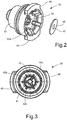
- Fig. 3 shows the insert sleeve 20 without the valve flap 46
- Fig. 2 the elastic valve flap 46 is shown close to the insert bushing 20 prior to its assembly
- Fig. 1 shows the valve flap 46 in the assembled state.
- the illustrated insert bushing 20 has at its axially lower end remote from the shift piston two radially protruding connecting flanges 48, 49, which are formed with associated inner flange segments at the lower axial end of the housing 4 50, 52 cooperate and form the bayonet lock 56 mentioned.
- To assemble the insert bushing 20 it is inserted axially into the housing 4 against the force of the tension spring 18 and then rotated about its longitudinal axis, the outer flange segments 48, 49 of the insert bushing 20 engaging behind the associated inner flange segments 50, 52 of the housing 4. When the correct rotational position is reached, the outer flange segments 48, 49 are arranged radially on the outside in a respective circular segment-shaped locking opening 51, 53 of the housing 4.
- a central compensation opening 54 connecting the two piston sides is formed, by means of which pressure equalization between the upper and lower cylinder chambers of the housing 4 is possible during a switching movement of the switching piston.
- the actuating piston 8 and the insert bushing 20 are each sealed against the housing 4 by means of a sealing ring 9, 23.
Landscapes
- Engineering & Computer Science (AREA)
- Physics & Mathematics (AREA)
- Transportation (AREA)
- Mechanical Engineering (AREA)
- Fluid Mechanics (AREA)
- General Physics & Mathematics (AREA)
- Automation & Control Theory (AREA)
- Safety Valves (AREA)
Claims (9)
- Valve de limitation de pression (2), présentant un boîtier (4), un piston de commutation (8) déplaçable dans le boîtier (4) dans la direction d'un axe longitudinal du boîtier (6) entre une position de remplissage, une position de limitation de pression et une position de désaérage, une valve de séquence (16) sollicitée par ressort, pouvant être actionnée par le piston de commutation (8), libérant un canal de désaérage (40) dans la position de désaérage du piston de commutation (8), un ressort de commutation (12) sollicitant le piston de commutation (8) dans la direction de sa position de remplissage, un moyen de vissage d'ajustement pour précontraindre le ressort de commutation (12) et un ressort de tensionnement (18) précontraignant un piston (17) de la valve de séquence (16) en direction d'une application contre le piston de commutation (8), le boîtier (4) étant réalisé d'une seule pièce et présentant essentiellement la géométrie d'un corps tubulaire ouvert aux deux extrémités, le moyen de vissage d'ajustement précontraignant étant réalisé sous la forme d'un couvercle vissable (14) pouvant être vissé dans une extrémité axiale du boîtier (4), présentant une surface d'appui (15) pour l'extrémité associée du ressort de commutation (12), le ressort de tensionnement (18) étant précontraint axialement au moyen d'une douille d'insertion (20) pouvant être insérée dans l'autre extrémité du boîtier (4) éloignée du couvercle vissable, caractérisée en ce que la douille d'insertion (20) est fixée dans le boîtier (4) au moyen d'une fermeture à baïonnette (56).
- Valve de limitation de pression selon la revendication 1, caractérisée en ce que des moyens antirotation (58, 59) coopérants, s'encliquetant dans l'état monté de la douille d'insertion (20), sont réalisés d'une part au niveau de la douille d'insertion (20) et d'autre part au niveau du boîtier (4).
- Valve de limitation de pression selon l'une quelconque des revendications 1 et 2, caractérisée en ce qu'une première tubulure radialement extérieure (22) recevant le ressort de tensionnement (18), s'étendant dans la direction de l'intérieur du boîtier (4), est réalisée au niveau de la douille d'insertion (20), et en ce que le piston (17) de la valve de séquence (16) présente la forme d'une rainure annulaire, ouverte vers la tubulure radialement extérieure (22) et rabattue par-dessus son extrémité axiale intérieure.
- Valve de limitation de pression selon la revendication 3, caractérisée en ce qu'une deuxième tubulure (24), disposée radialement à l'intérieur de la première tubulure (22) et concentrique par rapport à celle-ci, est disposée au niveau de la douille d'insertion (20), laquelle est ouverte au niveau de ses deux extrémités axiales et traverse axialement, avec son extrémité axialement intérieure (26), une ouverture centrale dans le piston (17) de la valve de séquence (16) .
- Valve de limitation de pression selon la revendication 4, caractérisée en ce que l'extrémité ouverte tournée axialement vers l'extérieur de la tubulure radialement intérieure (24) de la douille d'insertion (20) est recouverte par un clapet de valve élastique (46) pouvant pivoter axialement vers l'extérieur, qui est retenu, au moyen de moyens de fixation (42a, 42b, 42c) réalisés au niveau de la tubulure radialement intérieure (24), contre cette dernière.
- Valve de limitation de pression selon l'une quelconque des revendications 1 à 5, caractérisée en ce que le piston de commutation (8) est traversé par une ouverture d'équilibrage (54) reliant les deux côtés du piston.
- Valve de limitation de pression selon l'une quelconque des revendications 1 à 6, caractérisée en ce qu'une chambre de liaison (34) réalisée dans le boîtier (4) est à chaque fois en liaison directe avec la tubulure d'entrée (32) et la tubulure de sortie (36) associées réalisées intégralement sur le boîtier (4).
- Valve de limitation de pression selon l'une quelconque des revendications 1 à 7, caractérisée en ce que la douille d'insertion (20) se compose d'un matériau en plastique.
- Valve de limitation de pression selon l'une quelconque des revendications 1 à 8, caractérisée en ce que le couvercle vissable (14) se compose d'un plastique.
Applications Claiming Priority (1)
| Application Number | Priority Date | Filing Date | Title |
|---|---|---|---|
| DE102018108976.7A DE102018108976A1 (de) | 2018-04-16 | 2018-04-16 | Druckbegrenzungsventil |
Publications (2)
| Publication Number | Publication Date |
|---|---|
| EP3556621A1 EP3556621A1 (fr) | 2019-10-23 |
| EP3556621B1 true EP3556621B1 (fr) | 2020-08-26 |
Family
ID=65911002
Family Applications (1)
| Application Number | Title | Priority Date | Filing Date |
|---|---|---|---|
| EP19164716.3A Active EP3556621B1 (fr) | 2018-04-16 | 2019-03-22 | Clapet de limitation de pression |
Country Status (2)
| Country | Link |
|---|---|
| EP (1) | EP3556621B1 (fr) |
| DE (1) | DE102018108976A1 (fr) |
Families Citing this family (3)
| Publication number | Priority date | Publication date | Assignee | Title |
|---|---|---|---|---|
| DE102018121718A1 (de) | 2018-09-06 | 2020-03-12 | Knorr-Bremse Systeme für Nutzfahrzeuge GmbH | Führungshülse zum Führen einer Manschette eines Relaisventils für einen elektropneumatischen Modulator für eine Bremsanlage für ein Fahrzeug, Führungshülsenvorrichtung mit einer Führungshülse, Relaisventil mit einer Führungshülsenvorrichtung und Verfahren zum Herstellen eines Relaisventils |
| CN112393010B (zh) * | 2020-11-13 | 2022-06-03 | 中国航发沈阳发动机研究所 | 一种燃气轮机电磁阀控放气阀 |
| EP4140840B1 (fr) | 2021-08-31 | 2024-03-13 | ZF CV Systems Europe BV | Soupape de purge pour un dispositif de séchage par air et dispositif de séchage par air et système à base d'air pressurisé et véhicule commercial |
Family Cites Families (9)
| Publication number | Priority date | Publication date | Assignee | Title |
|---|---|---|---|---|
| US3559688A (en) * | 1965-06-04 | 1971-02-02 | Mack Trucks | Fluid pressure regulating valve |
| DE2032006A1 (de) * | 1970-06-29 | 1972-01-13 | Robert Bosch Gmbh, 7000 Stuttgart | Druckregeleinnchtung |
| DE2922837A1 (de) * | 1979-06-06 | 1980-12-18 | Bosch Gmbh Robert | Druckbegrenzungsventil |
| US5234026A (en) * | 1992-06-29 | 1993-08-10 | Tescom Corporation | Pressure reducing regulator |
| DE4344416A1 (de) | 1993-12-24 | 1995-06-29 | Wabco Vermoegensverwaltung | Druckbegrenzungseinrichtung |
| US7575020B2 (en) * | 2006-08-28 | 2009-08-18 | Gm Global Technology Operations, Inc. | Multi stage pressure regulator |
| DE102016117607A1 (de) * | 2016-09-19 | 2018-03-22 | Knorr-Bremse Systeme für Nutzfahrzeuge GmbH | Druckregelventil für ein Luftaufbereitungssystem eines Nutzfahrzeugs |
| JP6769808B2 (ja) * | 2016-09-29 | 2020-10-14 | 株式会社ジェイテクト | 減圧弁装置 |
| EP3502824A1 (fr) * | 2017-12-19 | 2019-06-26 | WABCO Europe BVBA | Soupape de limitation de pression, système d'alimentation en air comprimé |
-
2018
- 2018-04-16 DE DE102018108976.7A patent/DE102018108976A1/de not_active Withdrawn
-
2019
- 2019-03-22 EP EP19164716.3A patent/EP3556621B1/fr active Active
Non-Patent Citations (1)
| Title |
|---|
| None * |
Also Published As
| Publication number | Publication date |
|---|---|
| DE102018108976A1 (de) | 2019-10-17 |
| EP3556621A1 (fr) | 2019-10-23 |
Similar Documents
| Publication | Publication Date | Title |
|---|---|---|
| EP0471142A2 (fr) | Soupape de réglage de la pression pour l'installation dans un conduit de purge d'un moteur à combustion interne | |
| EP1555154A1 (fr) | Tubulure de remplissage pour le remplissage de combustible dans un réservoir d'un véhicule | |
| EP3556621B1 (fr) | Clapet de limitation de pression | |
| DE2427528A1 (de) | Drosselventil, insbesondere fuer einen kraftfahrzeug-kuehlwasserkreislauf | |
| DE3151567C2 (de) | Abblase- und Rückschlagventil | |
| EP2962022B1 (fr) | Soupape de trop-plein | |
| EP1314921B1 (fr) | Vanne d'arret automatique | |
| CH666527A5 (de) | Magnetventil. | |
| DE19647027B4 (de) | Heizkörperventil | |
| DE20016214U1 (de) | Drosselventil zur selbsttätigen Regelung des Drucks im Kurbelgehäuse einer Brennkraftmaschine | |
| DE102010012018A1 (de) | Entlüftungsventil | |
| WO2020144213A1 (fr) | Soupape à sièges | |
| DE102021122477B4 (de) | Druckausgleichsvorrichtung | |
| DE3729326C2 (de) | Reifendruck-Steuerventil II | |
| DE102016103549B3 (de) | Ventilvorrichtung für eine Verbrennungskraftmaschine | |
| EP0038978A2 (fr) | Dispositif de réglage de pression avec indicateur pour au moins deux récipients sous pression interconnectés | |
| EP1001196B1 (fr) | Soupape de limitation de pression, en particulier pour des véhicules | |
| DE19912249C2 (de) | Ventil für eine Milchleitung | |
| DE102021100029A1 (de) | Arretiersystem | |
| EP4146964B1 (fr) | Soupape de commutation de vapeur de carburant et soupape de ventilation pour un moteur à combustion interne | |
| EP4146963B1 (fr) | Commutateur à vapeur de carburant et soupape de ventilation pour un moteur à combustion interne | |
| EP3477168B1 (fr) | Valve et système de freinage pneumatique | |
| DE102009015976B4 (de) | Ventil mit drehbarem Ventilglied | |
| EP2134994B1 (fr) | Dispositif de blocage d'un passage de fluide par une partie en forme de conduit au moyen d'un clapet antiretour, en particulier dans un appareil menager | |
| WO2021223890A1 (fr) | Soupape de commutation de vapeur de carburant et soupape de ventilation pour un moteur à combustion interne |
Legal Events
| Date | Code | Title | Description |
|---|---|---|---|
| PUAI | Public reference made under article 153(3) epc to a published international application that has entered the european phase |
Free format text: ORIGINAL CODE: 0009012 |
|
| STAA | Information on the status of an ep patent application or granted ep patent |
Free format text: STATUS: THE APPLICATION HAS BEEN PUBLISHED |
|
| AK | Designated contracting states |
Kind code of ref document: A1 Designated state(s): AL AT BE BG CH CY CZ DE DK EE ES FI FR GB GR HR HU IE IS IT LI LT LU LV MC MK MT NL NO PL PT RO RS SE SI SK SM TR |
|
| AX | Request for extension of the european patent |
Extension state: BA ME |
|
| STAA | Information on the status of an ep patent application or granted ep patent |
Free format text: STATUS: REQUEST FOR EXAMINATION WAS MADE |
|
| 17P | Request for examination filed |
Effective date: 20200423 |
|
| RBV | Designated contracting states (corrected) |
Designated state(s): AL AT BE BG CH CY CZ DE DK EE ES FI FR GB GR HR HU IE IS IT LI LT LU LV MC MK MT NL NO PL PT RO RS SE SI SK SM TR |
|
| GRAP | Despatch of communication of intention to grant a patent |
Free format text: ORIGINAL CODE: EPIDOSNIGR1 |
|
| STAA | Information on the status of an ep patent application or granted ep patent |
Free format text: STATUS: GRANT OF PATENT IS INTENDED |
|
| RIC1 | Information provided on ipc code assigned before grant |
Ipc: G05D 16/10 20060101ALI20200507BHEP Ipc: B60T 15/50 20060101AFI20200507BHEP |
|
| INTG | Intention to grant announced |
Effective date: 20200605 |
|
| GRAS | Grant fee paid |
Free format text: ORIGINAL CODE: EPIDOSNIGR3 |
|
| GRAA | (expected) grant |
Free format text: ORIGINAL CODE: 0009210 |
|
| STAA | Information on the status of an ep patent application or granted ep patent |
Free format text: STATUS: THE PATENT HAS BEEN GRANTED |
|
| AK | Designated contracting states |
Kind code of ref document: B1 Designated state(s): AL AT BE BG CH CY CZ DE DK EE ES FI FR GB GR HR HU IE IS IT LI LT LU LV MC MK MT NL NO PL PT RO RS SE SI SK SM TR |
|
| REG | Reference to a national code |
Ref country code: GB Ref legal event code: FG4D Free format text: NOT ENGLISH |
|
| REG | Reference to a national code |
Ref country code: CH Ref legal event code: EP |
|
| REG | Reference to a national code |
Ref country code: DE Ref legal event code: R096 Ref document number: 502019000168 Country of ref document: DE |
|
| REG | Reference to a national code |
Ref country code: AT Ref legal event code: REF Ref document number: 1306092 Country of ref document: AT Kind code of ref document: T Effective date: 20200915 |
|
| REG | Reference to a national code |
Ref country code: IE Ref legal event code: FG4D Free format text: LANGUAGE OF EP DOCUMENT: GERMAN |
|
| REG | Reference to a national code |
Ref country code: LT Ref legal event code: MG4D |
|
| PG25 | Lapsed in a contracting state [announced via postgrant information from national office to epo] |
Ref country code: PT Free format text: LAPSE BECAUSE OF FAILURE TO SUBMIT A TRANSLATION OF THE DESCRIPTION OR TO PAY THE FEE WITHIN THE PRESCRIBED TIME-LIMIT Effective date: 20201228 Ref country code: HR Free format text: LAPSE BECAUSE OF FAILURE TO SUBMIT A TRANSLATION OF THE DESCRIPTION OR TO PAY THE FEE WITHIN THE PRESCRIBED TIME-LIMIT Effective date: 20200826 Ref country code: LT Free format text: LAPSE BECAUSE OF FAILURE TO SUBMIT A TRANSLATION OF THE DESCRIPTION OR TO PAY THE FEE WITHIN THE PRESCRIBED TIME-LIMIT Effective date: 20200826 Ref country code: SE Free format text: LAPSE BECAUSE OF FAILURE TO SUBMIT A TRANSLATION OF THE DESCRIPTION OR TO PAY THE FEE WITHIN THE PRESCRIBED TIME-LIMIT Effective date: 20200826 Ref country code: BG Free format text: LAPSE BECAUSE OF FAILURE TO SUBMIT A TRANSLATION OF THE DESCRIPTION OR TO PAY THE FEE WITHIN THE PRESCRIBED TIME-LIMIT Effective date: 20201126 Ref country code: GR Free format text: LAPSE BECAUSE OF FAILURE TO SUBMIT A TRANSLATION OF THE DESCRIPTION OR TO PAY THE FEE WITHIN THE PRESCRIBED TIME-LIMIT Effective date: 20201127 Ref country code: FI Free format text: LAPSE BECAUSE OF FAILURE TO SUBMIT A TRANSLATION OF THE DESCRIPTION OR TO PAY THE FEE WITHIN THE PRESCRIBED TIME-LIMIT Effective date: 20200826 Ref country code: NO Free format text: LAPSE BECAUSE OF FAILURE TO SUBMIT A TRANSLATION OF THE DESCRIPTION OR TO PAY THE FEE WITHIN THE PRESCRIBED TIME-LIMIT Effective date: 20201126 |
|
| REG | Reference to a national code |
Ref country code: NL Ref legal event code: MP Effective date: 20200826 |
|
| PG25 | Lapsed in a contracting state [announced via postgrant information from national office to epo] |
Ref country code: PL Free format text: LAPSE BECAUSE OF FAILURE TO SUBMIT A TRANSLATION OF THE DESCRIPTION OR TO PAY THE FEE WITHIN THE PRESCRIBED TIME-LIMIT Effective date: 20200826 Ref country code: RS Free format text: LAPSE BECAUSE OF FAILURE TO SUBMIT A TRANSLATION OF THE DESCRIPTION OR TO PAY THE FEE WITHIN THE PRESCRIBED TIME-LIMIT Effective date: 20200826 Ref country code: NL Free format text: LAPSE BECAUSE OF FAILURE TO SUBMIT A TRANSLATION OF THE DESCRIPTION OR TO PAY THE FEE WITHIN THE PRESCRIBED TIME-LIMIT Effective date: 20200826 Ref country code: LV Free format text: LAPSE BECAUSE OF FAILURE TO SUBMIT A TRANSLATION OF THE DESCRIPTION OR TO PAY THE FEE WITHIN THE PRESCRIBED TIME-LIMIT Effective date: 20200826 Ref country code: IS Free format text: LAPSE BECAUSE OF FAILURE TO SUBMIT A TRANSLATION OF THE DESCRIPTION OR TO PAY THE FEE WITHIN THE PRESCRIBED TIME-LIMIT Effective date: 20201226 |
|
| PG25 | Lapsed in a contracting state [announced via postgrant information from national office to epo] |
Ref country code: SM Free format text: LAPSE BECAUSE OF FAILURE TO SUBMIT A TRANSLATION OF THE DESCRIPTION OR TO PAY THE FEE WITHIN THE PRESCRIBED TIME-LIMIT Effective date: 20200826 Ref country code: RO Free format text: LAPSE BECAUSE OF FAILURE TO SUBMIT A TRANSLATION OF THE DESCRIPTION OR TO PAY THE FEE WITHIN THE PRESCRIBED TIME-LIMIT Effective date: 20200826 Ref country code: DK Free format text: LAPSE BECAUSE OF FAILURE TO SUBMIT A TRANSLATION OF THE DESCRIPTION OR TO PAY THE FEE WITHIN THE PRESCRIBED TIME-LIMIT Effective date: 20200826 Ref country code: CZ Free format text: LAPSE BECAUSE OF FAILURE TO SUBMIT A TRANSLATION OF THE DESCRIPTION OR TO PAY THE FEE WITHIN THE PRESCRIBED TIME-LIMIT Effective date: 20200826 Ref country code: EE Free format text: LAPSE BECAUSE OF FAILURE TO SUBMIT A TRANSLATION OF THE DESCRIPTION OR TO PAY THE FEE WITHIN THE PRESCRIBED TIME-LIMIT Effective date: 20200826 |
|
| RAP4 | Party data changed (patent owner data changed or rights of a patent transferred) |
Owner name: ZF CV SYSTEMS EUROPE BV |
|
| REG | Reference to a national code |
Ref country code: DE Ref legal event code: R097 Ref document number: 502019000168 Country of ref document: DE |
|
| PG25 | Lapsed in a contracting state [announced via postgrant information from national office to epo] |
Ref country code: AL Free format text: LAPSE BECAUSE OF FAILURE TO SUBMIT A TRANSLATION OF THE DESCRIPTION OR TO PAY THE FEE WITHIN THE PRESCRIBED TIME-LIMIT Effective date: 20200826 Ref country code: ES Free format text: LAPSE BECAUSE OF FAILURE TO SUBMIT A TRANSLATION OF THE DESCRIPTION OR TO PAY THE FEE WITHIN THE PRESCRIBED TIME-LIMIT Effective date: 20200826 |
|
| PG25 | Lapsed in a contracting state [announced via postgrant information from national office to epo] |
Ref country code: SK Free format text: LAPSE BECAUSE OF FAILURE TO SUBMIT A TRANSLATION OF THE DESCRIPTION OR TO PAY THE FEE WITHIN THE PRESCRIBED TIME-LIMIT Effective date: 20200826 |
|
| PLBE | No opposition filed within time limit |
Free format text: ORIGINAL CODE: 0009261 |
|
| STAA | Information on the status of an ep patent application or granted ep patent |
Free format text: STATUS: NO OPPOSITION FILED WITHIN TIME LIMIT |
|
| PG25 | Lapsed in a contracting state [announced via postgrant information from national office to epo] |
Ref country code: IT Free format text: LAPSE BECAUSE OF FAILURE TO SUBMIT A TRANSLATION OF THE DESCRIPTION OR TO PAY THE FEE WITHIN THE PRESCRIBED TIME-LIMIT Effective date: 20200826 |
|
| 26N | No opposition filed |
Effective date: 20210527 |
|
| PG25 | Lapsed in a contracting state [announced via postgrant information from national office to epo] |
Ref country code: SI Free format text: LAPSE BECAUSE OF FAILURE TO SUBMIT A TRANSLATION OF THE DESCRIPTION OR TO PAY THE FEE WITHIN THE PRESCRIBED TIME-LIMIT Effective date: 20200826 |
|
| REG | Reference to a national code |
Ref country code: DE Ref legal event code: R081 Ref document number: 502019000168 Country of ref document: DE Owner name: ZF CV SYSTEMS EUROPE BV, BE Free format text: FORMER OWNER: WABCO EUROPE BVBA, BRUESSEL, BE |
|
| PG25 | Lapsed in a contracting state [announced via postgrant information from national office to epo] |
Ref country code: MC Free format text: LAPSE BECAUSE OF FAILURE TO SUBMIT A TRANSLATION OF THE DESCRIPTION OR TO PAY THE FEE WITHIN THE PRESCRIBED TIME-LIMIT Effective date: 20200826 |
|
| REG | Reference to a national code |
Ref country code: BE Ref legal event code: MM Effective date: 20210331 |
|
| PG25 | Lapsed in a contracting state [announced via postgrant information from national office to epo] |
Ref country code: IE Free format text: LAPSE BECAUSE OF NON-PAYMENT OF DUE FEES Effective date: 20210322 Ref country code: LU Free format text: LAPSE BECAUSE OF NON-PAYMENT OF DUE FEES Effective date: 20210322 |
|
| PG25 | Lapsed in a contracting state [announced via postgrant information from national office to epo] |
Ref country code: BE Free format text: LAPSE BECAUSE OF NON-PAYMENT OF DUE FEES Effective date: 20210331 |
|
| REG | Reference to a national code |
Ref country code: CH Ref legal event code: PL |
|
| PG25 | Lapsed in a contracting state [announced via postgrant information from national office to epo] |
Ref country code: LI Free format text: LAPSE BECAUSE OF NON-PAYMENT OF DUE FEES Effective date: 20220331 Ref country code: CH Free format text: LAPSE BECAUSE OF NON-PAYMENT OF DUE FEES Effective date: 20220331 |
|
| PG25 | Lapsed in a contracting state [announced via postgrant information from national office to epo] |
Ref country code: CY Free format text: LAPSE BECAUSE OF FAILURE TO SUBMIT A TRANSLATION OF THE DESCRIPTION OR TO PAY THE FEE WITHIN THE PRESCRIBED TIME-LIMIT Effective date: 20200826 |
|
| P01 | Opt-out of the competence of the unified patent court (upc) registered |
Effective date: 20230528 |
|
| PG25 | Lapsed in a contracting state [announced via postgrant information from national office to epo] |
Ref country code: HU Free format text: LAPSE BECAUSE OF FAILURE TO SUBMIT A TRANSLATION OF THE DESCRIPTION OR TO PAY THE FEE WITHIN THE PRESCRIBED TIME-LIMIT; INVALID AB INITIO Effective date: 20190322 |
|
| PG25 | Lapsed in a contracting state [announced via postgrant information from national office to epo] |
Ref country code: MK Free format text: LAPSE BECAUSE OF FAILURE TO SUBMIT A TRANSLATION OF THE DESCRIPTION OR TO PAY THE FEE WITHIN THE PRESCRIBED TIME-LIMIT Effective date: 20200826 |
|
| PG25 | Lapsed in a contracting state [announced via postgrant information from national office to epo] |
Ref country code: TR Free format text: LAPSE BECAUSE OF FAILURE TO SUBMIT A TRANSLATION OF THE DESCRIPTION OR TO PAY THE FEE WITHIN THE PRESCRIBED TIME-LIMIT Effective date: 20200826 |
|
| PG25 | Lapsed in a contracting state [announced via postgrant information from national office to epo] |
Ref country code: MT Free format text: LAPSE BECAUSE OF FAILURE TO SUBMIT A TRANSLATION OF THE DESCRIPTION OR TO PAY THE FEE WITHIN THE PRESCRIBED TIME-LIMIT Effective date: 20200826 |
|
| PGFP | Annual fee paid to national office [announced via postgrant information from national office to epo] |
Ref country code: DE Payment date: 20241231 Year of fee payment: 7 |
|
| PGFP | Annual fee paid to national office [announced via postgrant information from national office to epo] |
Ref country code: FR Payment date: 20250210 Year of fee payment: 7 |
|
| PGFP | Annual fee paid to national office [announced via postgrant information from national office to epo] |
Ref country code: GB Payment date: 20250102 Year of fee payment: 7 |
|
| REG | Reference to a national code |
Ref country code: AT Ref legal event code: MM01 Ref document number: 1306092 Country of ref document: AT Kind code of ref document: T Effective date: 20240322 |
|
| PG25 | Lapsed in a contracting state [announced via postgrant information from national office to epo] |
Ref country code: AT Free format text: LAPSE BECAUSE OF NON-PAYMENT OF DUE FEES Effective date: 20240322 |