EP3557059A1 - Volumetrische membranpumpe - Google Patents
Volumetrische membranpumpe Download PDFInfo
- Publication number
- EP3557059A1 EP3557059A1 EP19161805.7A EP19161805A EP3557059A1 EP 3557059 A1 EP3557059 A1 EP 3557059A1 EP 19161805 A EP19161805 A EP 19161805A EP 3557059 A1 EP3557059 A1 EP 3557059A1
- Authority
- EP
- European Patent Office
- Prior art keywords
- piston
- guide cylinder
- pump
- centre position
- dead centre
- Prior art date
- Legal status (The legal status is an assumption and is not a legal conclusion. Google has not performed a legal analysis and makes no representation as to the accuracy of the status listed.)
- Granted
Links
Images
Classifications
-
- F—MECHANICAL ENGINEERING; LIGHTING; HEATING; WEAPONS; BLASTING
- F04—POSITIVE - DISPLACEMENT MACHINES FOR LIQUIDS; PUMPS FOR LIQUIDS OR ELASTIC FLUIDS
- F04B—POSITIVE-DISPLACEMENT MACHINES FOR LIQUIDS; PUMPS
- F04B43/00—Machines, pumps, or pumping installations having flexible working members
- F04B43/02—Machines, pumps, or pumping installations having flexible working members having plate-like flexible members, e.g. diaphragms
- F04B43/06—Pumps having fluid drive
-
- F—MECHANICAL ENGINEERING; LIGHTING; HEATING; WEAPONS; BLASTING
- F04—POSITIVE - DISPLACEMENT MACHINES FOR LIQUIDS; PUMPS FOR LIQUIDS OR ELASTIC FLUIDS
- F04B—POSITIVE-DISPLACEMENT MACHINES FOR LIQUIDS; PUMPS
- F04B53/00—Component parts, details or accessories not provided for in, or of interest apart from, groups F04B1/00 - F04B23/00 or F04B39/00 - F04B47/00
- F04B53/06—Venting
Definitions
- the present invention relates to a volumetric membrane pump suitable for being used in the agricultural field, for example for spraying protective liquids, fertilizing liquids or liquids of other type over the crops.
- volumetric membrane pumps comprise a guide cylinder, a flexible membrane placed to close an axial end of the guide cylinder, a head suitable for cooperating with the membrane to define a pumping chamber, and a piston fixed to the membrane and slidingly housed in the guide cylinder.
- the piston is connected to a drive kinematism, typically of the connecting rod-crank type, which allows it to slide between an upper dead centre position and a lower dead centre position.
- the piston By sliding towards the lower dead centre position, the piston performs a suction stroke in which it drags the membrane away from the head, thus increasing the volume of the pumping chamber and sucking liquid through an inlet valve.
- the piston By sliding vice versa towards the upper dead centre position, the piston performs a compression stroke in which it pushes the membrane close to the head, thus reducing the volume of the pumping chamber and pushing the liquid out through an outlet valve.
- the drive kinematism generally is enclosed in a casing, which internal volume is filled with lubricating oil so as to keep lubricated the piston and the other movable parts of the pump.
- the guide cylinder has at least one passage which when the piston is in the lower dead centre position, is suitable for placing the internal volume of the casing in communication with an intermediate chamber defined inside the guide cylinder between the membrane and the top of the piston.
- the lubricating oil also fills the intermediate chamber of the cylinder and being incompressible, allows actively supporting the membrane during the compression stroke, thus transferring the thrust exerted by the piston to it in substantially uniform manner.
- the piston also compresses the air inside the intermediate chamber, thus creating a vacuum in the volume of oil behind the membrane that affects the operation and duration thereof.
- volumetric membrane pump comprising:
- the air possibly trapped inside the intermediate chamber may always and easily flow towards the internal volume of the casing through the secondary passage without stagnating and therefore without creating that vacuum in the volume of oil behind the membrane that could worsen the operation and duration thereof.
- the secondary passage may be made in the guide cylinder.
- This solution provides a very simple construction method for placing the intermediate chamber of the guide cylinder in communication with the internal volume of the casing.
- the secondary passage may have a passing through cross-section which extension is less than 0.2 mm 2 , and more preferably, less than 0.05 mm 2 .
- the secondary passage generates a rather increased hydraulic resistance which even though it allows the outlet of the air, it allows keeping the lubricating oil inside the intermediate chamber also during the compression stroke of the piston, or it at least allows having only a minimum leak that does not affect the pressure of the lubricating oil in the intermediate chamber in an apparent manner.
- the secondary passage may be made in the shape of a through hole, which may have a diameter less than 0.5 mm, and more preferably, less than or equal to 0.2 mm.
- the pump may comprise a plurality of secondary passages, which may be for example, arranged angularly equidistant from one another about a longitudinal axis of the guide cylinder.
- the invention relates to a volumetric membrane pump 100 for pumping fluids, in particular for pumping liquids.
- the pump 100 may be used in the agricultural field for pumping protective liquids, fertilizing liquids or liquids of other type towards specific dispensing nozzles intended to spray or in any case dispense such liquids over the crops.
- the pump 100 it is not excluded for the pump 100 to also be used in other fields and/or for pumping other types of fluids.
- the pump 100 may comprise a drive shaft 105 that is suitable for rotating on itself about its middle axis X.
- the rotation of the drive shaft 105 may be obtained by means of direct or indirect connection with a thermic engine, for example with the motor of an agricultural tractor through a power take-off, or with an electric motor.
- the pump 100 also comprises a guide cylinder or sleeve 110 having a longitudinal axis Y that may be oriented perpendicularly to the middle axis X of the drive shaft 105.
- a piston 115 is slidingly housed inside the guide cylinder 110, which piston is connected to the drive shaft 105 through a kinematism 120 that is suitable for transforming the rotary movement of the drive shaft 105 into a linear and reciprocating movement of the piston 115 inside the guide cylinder 110.
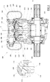
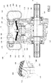
- the piston 115 is cyclically suitable for moving between a lower dead centre position, in which it is at the minimum distance from the drive shaft 105 (see fig. 2 ) and an upper dead centre position, in which it is at the maximum distance from the drive shaft 105 (see fig. 1 ).
- a coaxial sealing ring 200 may be interposed between the outer side surface of the piston 115 and the inner side surface of the guide cylinder 12, which coaxial sealing ring may be axially blocked inside a corresponding cavity made in the piston 115.
- the kinematism 120 comprises an eccentric 125 rigidly fixed to the drive shaft 105, for example made in a single piece therewith, and a connecting rod 130 articulated to said eccentric 125 and to a transverse pin 135 of the piston 115.
- the eccentric 125 may have a substantially cylindrical shape with axis parallel to but spaced apart from the middle axis X of the drive shaft 105.
- a thrust linkage is obtained capable of transforming the rotary movement of the drive shaft 105 into a reciprocating movement of the piston 115.
- the pump 100 also comprises a casing 140 that cooperates with the guide cylinder 110 and with the piston 115 to define a closed internal volume 145 that contains the kinematism 120, i.e. in the example, at least the connecting rod 130, the eccentric 125 and the transverse pin 135.
- the internal volume 145 may also contain bench bearings for the drive shaft 105 and/or a stretch of the drive shaft 105 comprised between said bench bearings.
- the guide cylinder 110 may be shaped so as to at least partially extend inside the casing 140, substantially in cantilevered manner, so that an annular gap belonging to the internal volume 145 is defined between the outer side surface of the guide cylinder 110 and the inner surface of the casing 140.
- the internal volume 145 is completely filled with lubricating oil, a function of which is to keep the piston 115 and the kinematism 120 lubricated.
- the casing 140 is made as a separate body with respect to the guide cylinder 110, to which it may be fixed by means of threaded members.
- the guide cylinder 110 and the casing 140 do not exclude for the guide cylinder 110 and the casing 140 to have a different geometry and/or to be made in a single piece.
- a flexible membrane 150 which may be made of elastomeric material (typically rubber).
- the flexible membrane 150 is interposed and blocked between the free end of the guide cylinder 110 and a head 155, which may be fixed to said guide cylinder 110 and/or to the casing 140, for example by means of threaded members, and is suitable for cooperating with the flexible membrane 150 to define a pumping chamber 160.
- the head 155 may be provided with an automatic inlet valve 165 suitable for selectively placing the pumping chamber 160 in communication with an inlet manifold 170, and with an automatic outlet valve 175 suitable for selectively placing the pumping chamber 160 in communication with a delivery manifold 180.
- the piston 115 is positioned outside the pumping chamber 160 and is fixed to the flexible membrane 150.
- the outer surface of the flexible membrane 150 i.e. the one facing the drive shaft 105, may be placed in contact with and fixed to the thrust surface (or top) of the piston 115, for example by means of a screw 185 and a fixing washer 190 placed in middle position both with respect to the flexible membrane 150 and with respect to the piston 115.
- An intermediate chamber 195 is further defined inside the guide cylinder 110, between the flexible membrane 150 and the top of the piston 115.
- the intermediate chamber 195 is in communication with the internal volume 145 of the casing 140 through one or more primary passages 205, each of which may be made in the shape of a through hole that radially crosses the wall of the guide cylinder 110.
- two primary passages 205 are shown, arranged on diametrically opposite sides of the guide cylinder 110. However, it is not excluded in other embodiments for there to be a larger number of primary passages 205, possibly arranged angularly equidistant from one another with respect to the longitudinal axis Y of the guide cylinder 110.
- the sealing ring 200 when the piston 115 is in the lower dead centre position, the sealing ring 200 is positioned below or at least at the aforesaid primary passages 205, thus allowing the latter to create a direct communication between the intermediate chamber 195 and the internal volume 145 of the casing 140. In this manner, when the internal volume 145 of the casing 140 is filled with the lubricating oil, the latter may also penetrate and completely fill the intermediate chamber 195, thus creating a lubricating oil cushion which concurs to transmitting the thrust exerted by the piston 115 during the compression stroke, to the flexible membrane 150.
- the sealing ring 200 first moves above the primary passages 205, closing the communication with the internal volume 145 of the casing 140, and then pressurizes the lubricating oil contained in the intermediate chamber 195, which by being incompressible, transmits the pressure directly to the flexible membrane 150, thus deforming it.
- the pump 100 further comprises one or more secondary passages 210, each of which is suitable for placing the intermediate chamber 195 in communication with the internal volume 145 of the casing 140 also when the piston 115 is in upper dead centre position and, preferably, for any position of the piston 115 inside the guide cylinder 110.
- Each of these secondary passages 210 may be made in the guide cylinder 110, for example in the shape of a through hole which crosses the side wall of the guide cylinder 110 close to the flexible membrane 150.
- each secondary passage 210 it is preferable for each secondary passage 210 to make available a sufficiently large cross section of passage to allow the evacuation of any air locks that may accumulate in the intermediate chamber 195, for example during the filling step with the lubricating oil, but sufficiently small enough to prevent the outlet of the lubricating oil during the compression stroke of the piston 115, or at least so as to allow only a minimum leak that does not affect the pressure of the lubricating oil in the intermediate chamber 195 in an apparent manner.
- each secondary passage 210 it is preferable for the passing through cross-section of each secondary passage 210 to have an extension which is less than 0.2 mm 2 , and more preferably less than 0.05 mm 2 .
- each secondary passage 210 may be made like a through hole having a diameter less than 0.5 mm, and more preferably, less than or equal to 0.2 mm.
- Such through hole may also have a rectilinear but inclined extension with respect to the longitudinal axis Y of the guide cylinder 110, for example with an efferent end in the intermediate chamber 195 that is placed closer to the flexible membrane 150 with respect to the opposite efferent end in the internal volume 145 of the casing 140.
- two identical secondary passages 210 are shown, arranged on diametrically opposite sides of the guide cylinder 110. However, it is not excluded in other embodiments for there to be a greater number of secondary passages 210, possibly arranged angularly equidistant from one another with respect to the longitudinal axis Y of the guide cylinder 110.
- each primary passage 205 preferably is greater with respect to the cross section of passage of each secondary passage 210 so that during the filling step of the pump 100, the lubricating oil may easily flow into and fill the intermediate chamber 195, as explained above.
Landscapes
- Engineering & Computer Science (AREA)
- Mechanical Engineering (AREA)
- General Engineering & Computer Science (AREA)
- Reciprocating Pumps (AREA)
Applications Claiming Priority (1)
| Application Number | Priority Date | Filing Date | Title |
|---|---|---|---|
| IT102018000004722A IT201800004722A1 (it) | 2018-04-19 | 2018-04-19 | Pompa volumetrica a membrana |
Publications (2)
| Publication Number | Publication Date |
|---|---|
| EP3557059A1 true EP3557059A1 (de) | 2019-10-23 |
| EP3557059B1 EP3557059B1 (de) | 2020-11-11 |
Family
ID=62952257
Family Applications (1)
| Application Number | Title | Priority Date | Filing Date |
|---|---|---|---|
| EP19161805.7A Active EP3557059B1 (de) | 2018-04-19 | 2019-03-11 | Volumetrische membranpumpe |
Country Status (3)
| Country | Link |
|---|---|
| EP (1) | EP3557059B1 (de) |
| DK (1) | DK3557059T3 (de) |
| IT (1) | IT201800004722A1 (de) |
Cited By (1)
| Publication number | Priority date | Publication date | Assignee | Title |
|---|---|---|---|---|
| DE102024202261A1 (de) * | 2024-03-11 | 2025-09-11 | Robert Bosch Gesellschaft mit beschränkter Haftung | Membranpumpe |
Citations (5)
| Publication number | Priority date | Publication date | Assignee | Title |
|---|---|---|---|---|
| US3075468A (en) * | 1960-04-06 | 1963-01-29 | Hills Mccanna Co | Hydraulically actuated diaphragm pump |
| US5246351A (en) * | 1991-12-17 | 1993-09-21 | Lews Herbert Ott Gmbh & Co. | Hydraulically driven diaphragm pump with diaphragm stroke limitation |
| WO2000068574A1 (en) * | 1999-05-11 | 2000-11-16 | Milton Roy Company | Multifunction valve |
| WO2004106884A1 (en) * | 2003-05-16 | 2004-12-09 | Wanner Engineering, Inc. | Diaphragm pump |
| EP2921705A1 (de) * | 2014-03-20 | 2015-09-23 | Annovi Reverberi S.p.A. | Membranplattengruppe für Membranpumpen |
-
2018
- 2018-04-19 IT IT102018000004722A patent/IT201800004722A1/it unknown
-
2019
- 2019-03-11 EP EP19161805.7A patent/EP3557059B1/de active Active
- 2019-03-11 DK DK19161805.7T patent/DK3557059T3/da active
Patent Citations (5)
| Publication number | Priority date | Publication date | Assignee | Title |
|---|---|---|---|---|
| US3075468A (en) * | 1960-04-06 | 1963-01-29 | Hills Mccanna Co | Hydraulically actuated diaphragm pump |
| US5246351A (en) * | 1991-12-17 | 1993-09-21 | Lews Herbert Ott Gmbh & Co. | Hydraulically driven diaphragm pump with diaphragm stroke limitation |
| WO2000068574A1 (en) * | 1999-05-11 | 2000-11-16 | Milton Roy Company | Multifunction valve |
| WO2004106884A1 (en) * | 2003-05-16 | 2004-12-09 | Wanner Engineering, Inc. | Diaphragm pump |
| EP2921705A1 (de) * | 2014-03-20 | 2015-09-23 | Annovi Reverberi S.p.A. | Membranplattengruppe für Membranpumpen |
Cited By (1)
| Publication number | Priority date | Publication date | Assignee | Title |
|---|---|---|---|---|
| DE102024202261A1 (de) * | 2024-03-11 | 2025-09-11 | Robert Bosch Gesellschaft mit beschränkter Haftung | Membranpumpe |
Also Published As
| Publication number | Publication date |
|---|---|
| DK3557059T3 (da) | 2021-02-15 |
| IT201800004722A1 (it) | 2019-10-19 |
| EP3557059B1 (de) | 2020-11-11 |
Similar Documents
| Publication | Publication Date | Title |
|---|---|---|
| EP2860396B1 (de) | Pumpe | |
| EP0985825B1 (de) | Kolbenpumpe für Schmiermittel | |
| EP2684386B1 (de) | Pumpenkopf-auslassöffnung | |
| US3666382A (en) | Pump | |
| US4790728A (en) | Dual-rigid-hollow-stem actuators in opposite-phase slurry pump drive having variable pumping speed and force | |
| CN109416039B (zh) | 活塞泵和密封圈 | |
| EP3557059B1 (de) | Volumetrische membranpumpe | |
| US8226383B2 (en) | Downhole pump | |
| CN110345371A (zh) | 自润滑泵的喉部密封件 | |
| CN206092576U (zh) | 一种双作用伸缩油缸 | |
| US1432041A (en) | Pump | |
| US9341173B2 (en) | Lance pump with a ram | |
| EP3578811B1 (de) | Volumetrische kolbenpumpe | |
| EP2058517A1 (de) | Pumpe | |
| US7661935B2 (en) | High pressure pump | |
| US2446748A (en) | etter | |
| US3199457A (en) | Reciprocating pump | |
| DE1001111B (de) | Membrankolbenpumpe, insbesondere zur Foerderung von Fluessigkeiten aus grossen Tiefen | |
| RU227071U1 (ru) | Мембранно-поршневой насос для подачи рабочей жидкости опрыскивателя | |
| KR200149505Y1 (ko) | 슬라이딩 개폐식 플런저 펌프 | |
| KR20100003932A (ko) | 이송 피스톤 펌프 | |
| SU603767A1 (ru) | Насос | |
| US3298317A (en) | High pressure variable volume pump | |
| RU171538U1 (ru) | Скважинная насосная установка | |
| RU2578777C1 (ru) | Плунжерный насос высокого давления |
Legal Events
| Date | Code | Title | Description |
|---|---|---|---|
| PUAI | Public reference made under article 153(3) epc to a published international application that has entered the european phase |
Free format text: ORIGINAL CODE: 0009012 |
|
| STAA | Information on the status of an ep patent application or granted ep patent |
Free format text: STATUS: THE APPLICATION HAS BEEN PUBLISHED |
|
| AK | Designated contracting states |
Kind code of ref document: A1 Designated state(s): AL AT BE BG CH CY CZ DE DK EE ES FI FR GB GR HR HU IE IS IT LI LT LU LV MC MK MT NL NO PL PT RO RS SE SI SK SM TR |
|
| AX | Request for extension of the european patent |
Extension state: BA ME |
|
| STAA | Information on the status of an ep patent application or granted ep patent |
Free format text: STATUS: REQUEST FOR EXAMINATION WAS MADE |
|
| 17P | Request for examination filed |
Effective date: 20200416 |
|
| RBV | Designated contracting states (corrected) |
Designated state(s): AL AT BE BG CH CY CZ DE DK EE ES FI FR GB GR HR HU IE IS IT LI LT LU LV MC MK MT NL NO PL PT RO RS SE SI SK SM TR |
|
| GRAP | Despatch of communication of intention to grant a patent |
Free format text: ORIGINAL CODE: EPIDOSNIGR1 |
|
| STAA | Information on the status of an ep patent application or granted ep patent |
Free format text: STATUS: GRANT OF PATENT IS INTENDED |
|
| RIC1 | Information provided on ipc code assigned before grant |
Ipc: F04B 53/06 20060101ALI20200527BHEP Ipc: F04B 43/06 20060101ALI20200527BHEP Ipc: F04B 43/02 20060101AFI20200527BHEP |
|
| INTG | Intention to grant announced |
Effective date: 20200615 |
|
| GRAS | Grant fee paid |
Free format text: ORIGINAL CODE: EPIDOSNIGR3 |
|
| GRAA | (expected) grant |
Free format text: ORIGINAL CODE: 0009210 |
|
| STAA | Information on the status of an ep patent application or granted ep patent |
Free format text: STATUS: THE PATENT HAS BEEN GRANTED |
|
| AK | Designated contracting states |
Kind code of ref document: B1 Designated state(s): AL AT BE BG CH CY CZ DE DK EE ES FI FR GB GR HR HU IE IS IT LI LT LU LV MC MK MT NL NO PL PT RO RS SE SI SK SM TR |
|
| REG | Reference to a national code |
Ref country code: GB Ref legal event code: FG4D |
|
| REG | Reference to a national code |
Ref country code: CH Ref legal event code: EP |
|
| REG | Reference to a national code |
Ref country code: AT Ref legal event code: REF Ref document number: 1333726 Country of ref document: AT Kind code of ref document: T Effective date: 20201115 |
|
| REG | Reference to a national code |
Ref country code: DE Ref legal event code: R096 Ref document number: 602019001238 Country of ref document: DE |
|
| REG | Reference to a national code |
Ref country code: IE Ref legal event code: FG4D |
|
| REG | Reference to a national code |
Ref country code: DK Ref legal event code: T3 Effective date: 20210210 |
|
| REG | Reference to a national code |
Ref country code: NL Ref legal event code: MP Effective date: 20201111 |
|
| REG | Reference to a national code |
Ref country code: AT Ref legal event code: MK05 Ref document number: 1333726 Country of ref document: AT Kind code of ref document: T Effective date: 20201111 |
|
| PG25 | Lapsed in a contracting state [announced via postgrant information from national office to epo] |
Ref country code: NO Free format text: LAPSE BECAUSE OF FAILURE TO SUBMIT A TRANSLATION OF THE DESCRIPTION OR TO PAY THE FEE WITHIN THE PRESCRIBED TIME-LIMIT Effective date: 20210211 Ref country code: GR Free format text: LAPSE BECAUSE OF FAILURE TO SUBMIT A TRANSLATION OF THE DESCRIPTION OR TO PAY THE FEE WITHIN THE PRESCRIBED TIME-LIMIT Effective date: 20210212 Ref country code: RS Free format text: LAPSE BECAUSE OF FAILURE TO SUBMIT A TRANSLATION OF THE DESCRIPTION OR TO PAY THE FEE WITHIN THE PRESCRIBED TIME-LIMIT Effective date: 20201111 Ref country code: PT Free format text: LAPSE BECAUSE OF FAILURE TO SUBMIT A TRANSLATION OF THE DESCRIPTION OR TO PAY THE FEE WITHIN THE PRESCRIBED TIME-LIMIT Effective date: 20210311 Ref country code: FI Free format text: LAPSE BECAUSE OF FAILURE TO SUBMIT A TRANSLATION OF THE DESCRIPTION OR TO PAY THE FEE WITHIN THE PRESCRIBED TIME-LIMIT Effective date: 20201111 |
|
| PG25 | Lapsed in a contracting state [announced via postgrant information from national office to epo] |
Ref country code: SE Free format text: LAPSE BECAUSE OF FAILURE TO SUBMIT A TRANSLATION OF THE DESCRIPTION OR TO PAY THE FEE WITHIN THE PRESCRIBED TIME-LIMIT Effective date: 20201111 Ref country code: PL Free format text: LAPSE BECAUSE OF FAILURE TO SUBMIT A TRANSLATION OF THE DESCRIPTION OR TO PAY THE FEE WITHIN THE PRESCRIBED TIME-LIMIT Effective date: 20201111 Ref country code: IS Free format text: LAPSE BECAUSE OF FAILURE TO SUBMIT A TRANSLATION OF THE DESCRIPTION OR TO PAY THE FEE WITHIN THE PRESCRIBED TIME-LIMIT Effective date: 20210311 Ref country code: LV Free format text: LAPSE BECAUSE OF FAILURE TO SUBMIT A TRANSLATION OF THE DESCRIPTION OR TO PAY THE FEE WITHIN THE PRESCRIBED TIME-LIMIT Effective date: 20201111 Ref country code: BG Free format text: LAPSE BECAUSE OF FAILURE TO SUBMIT A TRANSLATION OF THE DESCRIPTION OR TO PAY THE FEE WITHIN THE PRESCRIBED TIME-LIMIT Effective date: 20210211 Ref country code: AT Free format text: LAPSE BECAUSE OF FAILURE TO SUBMIT A TRANSLATION OF THE DESCRIPTION OR TO PAY THE FEE WITHIN THE PRESCRIBED TIME-LIMIT Effective date: 20201111 |
|
| REG | Reference to a national code |
Ref country code: LT Ref legal event code: MG9D |
|
| PG25 | Lapsed in a contracting state [announced via postgrant information from national office to epo] |
Ref country code: HR Free format text: LAPSE BECAUSE OF FAILURE TO SUBMIT A TRANSLATION OF THE DESCRIPTION OR TO PAY THE FEE WITHIN THE PRESCRIBED TIME-LIMIT Effective date: 20201111 |
|
| PG25 | Lapsed in a contracting state [announced via postgrant information from national office to epo] |
Ref country code: LT Free format text: LAPSE BECAUSE OF FAILURE TO SUBMIT A TRANSLATION OF THE DESCRIPTION OR TO PAY THE FEE WITHIN THE PRESCRIBED TIME-LIMIT Effective date: 20201111 Ref country code: RO Free format text: LAPSE BECAUSE OF FAILURE TO SUBMIT A TRANSLATION OF THE DESCRIPTION OR TO PAY THE FEE WITHIN THE PRESCRIBED TIME-LIMIT Effective date: 20201111 Ref country code: CZ Free format text: LAPSE BECAUSE OF FAILURE TO SUBMIT A TRANSLATION OF THE DESCRIPTION OR TO PAY THE FEE WITHIN THE PRESCRIBED TIME-LIMIT Effective date: 20201111 Ref country code: EE Free format text: LAPSE BECAUSE OF FAILURE TO SUBMIT A TRANSLATION OF THE DESCRIPTION OR TO PAY THE FEE WITHIN THE PRESCRIBED TIME-LIMIT Effective date: 20201111 Ref country code: SK Free format text: LAPSE BECAUSE OF FAILURE TO SUBMIT A TRANSLATION OF THE DESCRIPTION OR TO PAY THE FEE WITHIN THE PRESCRIBED TIME-LIMIT Effective date: 20201111 Ref country code: SM Free format text: LAPSE BECAUSE OF FAILURE TO SUBMIT A TRANSLATION OF THE DESCRIPTION OR TO PAY THE FEE WITHIN THE PRESCRIBED TIME-LIMIT Effective date: 20201111 |
|
| REG | Reference to a national code |
Ref country code: DE Ref legal event code: R097 Ref document number: 602019001238 Country of ref document: DE |
|
| PLBE | No opposition filed within time limit |
Free format text: ORIGINAL CODE: 0009261 |
|
| STAA | Information on the status of an ep patent application or granted ep patent |
Free format text: STATUS: NO OPPOSITION FILED WITHIN TIME LIMIT |
|
| 26N | No opposition filed |
Effective date: 20210812 |
|
| PG25 | Lapsed in a contracting state [announced via postgrant information from national office to epo] |
Ref country code: NL Free format text: LAPSE BECAUSE OF FAILURE TO SUBMIT A TRANSLATION OF THE DESCRIPTION OR TO PAY THE FEE WITHIN THE PRESCRIBED TIME-LIMIT Effective date: 20201111 Ref country code: AL Free format text: LAPSE BECAUSE OF FAILURE TO SUBMIT A TRANSLATION OF THE DESCRIPTION OR TO PAY THE FEE WITHIN THE PRESCRIBED TIME-LIMIT Effective date: 20201111 Ref country code: MC Free format text: LAPSE BECAUSE OF FAILURE TO SUBMIT A TRANSLATION OF THE DESCRIPTION OR TO PAY THE FEE WITHIN THE PRESCRIBED TIME-LIMIT Effective date: 20201111 |
|
| PG25 | Lapsed in a contracting state [announced via postgrant information from national office to epo] |
Ref country code: SI Free format text: LAPSE BECAUSE OF FAILURE TO SUBMIT A TRANSLATION OF THE DESCRIPTION OR TO PAY THE FEE WITHIN THE PRESCRIBED TIME-LIMIT Effective date: 20201111 |
|
| REG | Reference to a national code |
Ref country code: BE Ref legal event code: MM Effective date: 20210331 |
|
| PG25 | Lapsed in a contracting state [announced via postgrant information from national office to epo] |
Ref country code: ES Free format text: LAPSE BECAUSE OF FAILURE TO SUBMIT A TRANSLATION OF THE DESCRIPTION OR TO PAY THE FEE WITHIN THE PRESCRIBED TIME-LIMIT Effective date: 20201111 Ref country code: IE Free format text: LAPSE BECAUSE OF NON-PAYMENT OF DUE FEES Effective date: 20210311 Ref country code: LU Free format text: LAPSE BECAUSE OF NON-PAYMENT OF DUE FEES Effective date: 20210311 |
|
| PG25 | Lapsed in a contracting state [announced via postgrant information from national office to epo] |
Ref country code: IS Free format text: LAPSE BECAUSE OF FAILURE TO SUBMIT A TRANSLATION OF THE DESCRIPTION OR TO PAY THE FEE WITHIN THE PRESCRIBED TIME-LIMIT Effective date: 20210311 |
|
| PG25 | Lapsed in a contracting state [announced via postgrant information from national office to epo] |
Ref country code: BE Free format text: LAPSE BECAUSE OF NON-PAYMENT OF DUE FEES Effective date: 20210331 |
|
| REG | Reference to a national code |
Ref country code: CH Ref legal event code: PL |
|
| PG25 | Lapsed in a contracting state [announced via postgrant information from national office to epo] |
Ref country code: LI Free format text: LAPSE BECAUSE OF NON-PAYMENT OF DUE FEES Effective date: 20220331 Ref country code: CH Free format text: LAPSE BECAUSE OF NON-PAYMENT OF DUE FEES Effective date: 20220331 |
|
| P01 | Opt-out of the competence of the unified patent court (upc) registered |
Effective date: 20230513 |
|
| PG25 | Lapsed in a contracting state [announced via postgrant information from national office to epo] |
Ref country code: CY Free format text: LAPSE BECAUSE OF FAILURE TO SUBMIT A TRANSLATION OF THE DESCRIPTION OR TO PAY THE FEE WITHIN THE PRESCRIBED TIME-LIMIT Effective date: 20201111 |
|
| PG25 | Lapsed in a contracting state [announced via postgrant information from national office to epo] |
Ref country code: HU Free format text: LAPSE BECAUSE OF FAILURE TO SUBMIT A TRANSLATION OF THE DESCRIPTION OR TO PAY THE FEE WITHIN THE PRESCRIBED TIME-LIMIT; INVALID AB INITIO Effective date: 20190311 |
|
| PG25 | Lapsed in a contracting state [announced via postgrant information from national office to epo] |
Ref country code: MK Free format text: LAPSE BECAUSE OF FAILURE TO SUBMIT A TRANSLATION OF THE DESCRIPTION OR TO PAY THE FEE WITHIN THE PRESCRIBED TIME-LIMIT Effective date: 20201111 |
|
| PG25 | Lapsed in a contracting state [announced via postgrant information from national office to epo] |
Ref country code: MT Free format text: LAPSE BECAUSE OF FAILURE TO SUBMIT A TRANSLATION OF THE DESCRIPTION OR TO PAY THE FEE WITHIN THE PRESCRIBED TIME-LIMIT Effective date: 20201111 |
|
| PGFP | Annual fee paid to national office [announced via postgrant information from national office to epo] |
Ref country code: DE Payment date: 20250327 Year of fee payment: 7 |
|
| PGFP | Annual fee paid to national office [announced via postgrant information from national office to epo] |
Ref country code: DK Payment date: 20250325 Year of fee payment: 7 |
|
| PGFP | Annual fee paid to national office [announced via postgrant information from national office to epo] |
Ref country code: FR Payment date: 20250325 Year of fee payment: 7 |
|
| PGFP | Annual fee paid to national office [announced via postgrant information from national office to epo] |
Ref country code: IT Payment date: 20250128 Year of fee payment: 7 Ref country code: GB Payment date: 20250327 Year of fee payment: 7 |
|
| PG25 | Lapsed in a contracting state [announced via postgrant information from national office to epo] |
Ref country code: TR Free format text: LAPSE BECAUSE OF FAILURE TO SUBMIT A TRANSLATION OF THE DESCRIPTION OR TO PAY THE FEE WITHIN THE PRESCRIBED TIME-LIMIT Effective date: 20201111 |