EP3557096A1 - Entraînement à vis à bille à élément de transmission de forces et à compensation d'équilibrage et méthode - Google Patents
Entraînement à vis à bille à élément de transmission de forces et à compensation d'équilibrage et méthode Download PDFInfo
- Publication number
- EP3557096A1 EP3557096A1 EP18168493.7A EP18168493A EP3557096A1 EP 3557096 A1 EP3557096 A1 EP 3557096A1 EP 18168493 A EP18168493 A EP 18168493A EP 3557096 A1 EP3557096 A1 EP 3557096A1
- Authority
- EP
- European Patent Office
- Prior art keywords
- recess
- spindle nut
- transmission element
- ball screw
- spindle
- Prior art date
- Legal status (The legal status is an assumption and is not a legal conclusion. Google has not performed a legal analysis and makes no representation as to the accuracy of the status listed.)
- Granted
Links
Images

Classifications
-
- F—MECHANICAL ENGINEERING; LIGHTING; HEATING; WEAPONS; BLASTING
- F16—ENGINEERING ELEMENTS AND UNITS; GENERAL MEASURES FOR PRODUCING AND MAINTAINING EFFECTIVE FUNCTIONING OF MACHINES OR INSTALLATIONS; THERMAL INSULATION IN GENERAL
- F16H—GEARING
- F16H25/00—Gearings comprising primarily only cams, cam-followers and screw-and-nut mechanisms
- F16H25/18—Gearings comprising primarily only cams, cam-followers and screw-and-nut mechanisms for conveying or interconverting oscillating or reciprocating motions
- F16H25/20—Screw mechanisms
- F16H25/22—Screw mechanisms with balls, rollers, or similar members between the co-operating parts; Elements essential to the use of such members
- F16H25/2204—Screw mechanisms with balls, rollers, or similar members between the co-operating parts; Elements essential to the use of such members with balls
- F16H25/2209—Screw mechanisms with balls, rollers, or similar members between the co-operating parts; Elements essential to the use of such members with balls with arrangements for taking up backlash
-
- B—PERFORMING OPERATIONS; TRANSPORTING
- B62—LAND VEHICLES FOR TRAVELLING OTHERWISE THAN ON RAILS
- B62D—MOTOR VEHICLES; TRAILERS
- B62D5/00—Power-assisted or power-driven steering
- B62D5/04—Power-assisted or power-driven steering electrical, e.g. using an electric servo-motor connected to, or forming part of, the steering gear
- B62D5/0442—Conversion of rotational into longitudinal movement
- B62D5/0445—Screw drives
- B62D5/0448—Ball nuts
-
- F—MECHANICAL ENGINEERING; LIGHTING; HEATING; WEAPONS; BLASTING
- F16—ENGINEERING ELEMENTS AND UNITS; GENERAL MEASURES FOR PRODUCING AND MAINTAINING EFFECTIVE FUNCTIONING OF MACHINES OR INSTALLATIONS; THERMAL INSULATION IN GENERAL
- F16H—GEARING
- F16H25/00—Gearings comprising primarily only cams, cam-followers and screw-and-nut mechanisms
- F16H25/18—Gearings comprising primarily only cams, cam-followers and screw-and-nut mechanisms for conveying or interconverting oscillating or reciprocating motions
- F16H25/20—Screw mechanisms
- F16H25/22—Screw mechanisms with balls, rollers, or similar members between the co-operating parts; Elements essential to the use of such members
-
- F—MECHANICAL ENGINEERING; LIGHTING; HEATING; WEAPONS; BLASTING
- F16—ENGINEERING ELEMENTS AND UNITS; GENERAL MEASURES FOR PRODUCING AND MAINTAINING EFFECTIVE FUNCTIONING OF MACHINES OR INSTALLATIONS; THERMAL INSULATION IN GENERAL
- F16H—GEARING
- F16H25/00—Gearings comprising primarily only cams, cam-followers and screw-and-nut mechanisms
- F16H25/18—Gearings comprising primarily only cams, cam-followers and screw-and-nut mechanisms for conveying or interconverting oscillating or reciprocating motions
- F16H25/20—Screw mechanisms
- F16H25/22—Screw mechanisms with balls, rollers, or similar members between the co-operating parts; Elements essential to the use of such members
- F16H25/2204—Screw mechanisms with balls, rollers, or similar members between the co-operating parts; Elements essential to the use of such members with balls
- F16H25/2214—Screw mechanisms with balls, rollers, or similar members between the co-operating parts; Elements essential to the use of such members with balls with elements for guiding the circulating balls
-
- F—MECHANICAL ENGINEERING; LIGHTING; HEATING; WEAPONS; BLASTING
- F16—ENGINEERING ELEMENTS AND UNITS; GENERAL MEASURES FOR PRODUCING AND MAINTAINING EFFECTIVE FUNCTIONING OF MACHINES OR INSTALLATIONS; THERMAL INSULATION IN GENERAL
- F16H—GEARING
- F16H25/00—Gearings comprising primarily only cams, cam-followers and screw-and-nut mechanisms
- F16H25/18—Gearings comprising primarily only cams, cam-followers and screw-and-nut mechanisms for conveying or interconverting oscillating or reciprocating motions
- F16H25/20—Screw mechanisms
- F16H25/24—Elements essential to such mechanisms, e.g. screws, nuts
-
- F—MECHANICAL ENGINEERING; LIGHTING; HEATING; WEAPONS; BLASTING
- F16—ENGINEERING ELEMENTS AND UNITS; GENERAL MEASURES FOR PRODUCING AND MAINTAINING EFFECTIVE FUNCTIONING OF MACHINES OR INSTALLATIONS; THERMAL INSULATION IN GENERAL
- F16H—GEARING
- F16H25/00—Gearings comprising primarily only cams, cam-followers and screw-and-nut mechanisms
- F16H25/18—Gearings comprising primarily only cams, cam-followers and screw-and-nut mechanisms for conveying or interconverting oscillating or reciprocating motions
- F16H25/20—Screw mechanisms
- F16H2025/2062—Arrangements for driving the actuator
- F16H2025/2096—Arrangements for driving the actuator using endless flexible members
-
- F—MECHANICAL ENGINEERING; LIGHTING; HEATING; WEAPONS; BLASTING
- F16—ENGINEERING ELEMENTS AND UNITS; GENERAL MEASURES FOR PRODUCING AND MAINTAINING EFFECTIVE FUNCTIONING OF MACHINES OR INSTALLATIONS; THERMAL INSULATION IN GENERAL
- F16H—GEARING
- F16H25/00—Gearings comprising primarily only cams, cam-followers and screw-and-nut mechanisms
- F16H25/18—Gearings comprising primarily only cams, cam-followers and screw-and-nut mechanisms for conveying or interconverting oscillating or reciprocating motions
- F16H25/20—Screw mechanisms
- F16H25/24—Elements essential to such mechanisms, e.g. screws, nuts
- F16H2025/2445—Supports or other means for compensating misalignment or offset between screw and nut
-
- F—MECHANICAL ENGINEERING; LIGHTING; HEATING; WEAPONS; BLASTING
- F16—ENGINEERING ELEMENTS AND UNITS; GENERAL MEASURES FOR PRODUCING AND MAINTAINING EFFECTIVE FUNCTIONING OF MACHINES OR INSTALLATIONS; THERMAL INSULATION IN GENERAL
- F16H—GEARING
- F16H25/00—Gearings comprising primarily only cams, cam-followers and screw-and-nut mechanisms
- F16H25/18—Gearings comprising primarily only cams, cam-followers and screw-and-nut mechanisms for conveying or interconverting oscillating or reciprocating motions
- F16H25/20—Screw mechanisms
- F16H25/22—Screw mechanisms with balls, rollers, or similar members between the co-operating parts; Elements essential to the use of such members
- F16H25/2204—Screw mechanisms with balls, rollers, or similar members between the co-operating parts; Elements essential to the use of such members with balls
- F16H25/2214—Screw mechanisms with balls, rollers, or similar members between the co-operating parts; Elements essential to the use of such members with balls with elements for guiding the circulating balls
- F16H25/2223—Cross over deflectors between adjacent thread turns, e.g. S-form deflectors connecting neighbouring threads
Definitions
- the present invention is concerned with a ball screw, in particular with the spindle nut encompassing force transmission element, which utilizes features of the spindle nut for power dissipation, which in turn serve to balance the imbalance.
- a ball screw or ball screw (KGT) is usually called a Wälzschraubtrieb with balls as rolling elements.
- a ball screw works as a helical gear, the lower or translation is determined by the dimensioning of the threaded spindle, more precisely by the pitch of the thread.
- Ball screws are used in many technical applications, especially in mechanical engineering and preferably in machine tools. Increasingly, however, ball screws are also used as longitudinal drives in areas where hitherto mostly hydraulic systems have been used, e.g. in injection molding machines and power steering systems. In addition, ball screws also play an increasing role in electromechanical and electro-hydraulic brake systems, where ball screw are used as a replacement for hydraulic brake cylinder or parallel to known brake systems as an actuator of brake assist systems.
- FIG. 1 A ball screw according to the prior art is in FIG. 1 displayed.
- the main components of the ball screw 10 include a threaded spindle 12 and a spindle encompassing this spindle nut 14. Between these two components run balls in operation, the threads of the threaded spindle 12 as well as the spindle nut 14 are complementary and coordinated so that they Ball guides act.
- the spindle nut 14 consists of a nut body 13 which has (at least) an opening 17 for a ball deflection 15.
- This ball deflection 15 is shown here as an insert element, which is sunk in the opening 17.
- the deflection has the task to lift the balls at a first location from the ball guide between the spindle nut 14 and threaded spindle 12 and due to a second location.
- the ball return thus represents a bypass that bridges at least one, often multiple threads of the nut-spindle system. This creates a closed circulation path for the balls of the ball screw 10.
- the spindle nut Due to the construction of the spindle nut, this is often not symmetrical about its central axis of rotation. Especially the ball return or ball deflection ensures that the main axis of inertia of the spindle nut no longer coincides with the axis of rotation, which is defined by the axial center axis 18 of the spindle.
- One method of eliminating the imbalance is to provide as identical as possible mirror-symmetrical recesses as for the ball deflection (s) in the spindle nut and mounted offset by 180 ° axially.
- two socleh Aus GmbHsaus principle can be provided axially offset by 120 °. In terms of an imbalance caused by the ball deflection, however, this is complicated because of the complicated geometry.
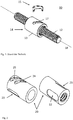
- FIG. 2 shows a spindle nut body 20 with two recesses 24 and 25, which are provided for ball return channels openings (recesses or recesses).
- Two recesses 22, 23 are provided to compensate for the imbalance caused by the ball deflection (s).
- the recesses 22, 23 are shown as grooves with a flat bottom, which is advantageous in terms of manufacturing technology, but deviates from the aforementioned recipe of the mirror-symmetrical recesses.
- Ball screw are usually used so that either the threaded spindle is stationary and is driven so that the spindle nut can move along the spindle or vice versa.
- both spindle and spindle nut elements be provided, which allow the component to securely hold or drive; in other words, to introduce or deduce a torque.
- gears are used for this, which can be manufactured as a separate component and pressed onto the spindle nut, welded or glued.
- other power transmission elements are conceivable as friction wheels, pulleys or the like.
- the term force transmission element should therefore be understood to mean all machine elements which allow torques to be transmitted to or from the spindle nut.
- the DE 10 2008 002 627 A1 describes a ball screw whose spindle nut has compensation means which counteract an imbalance resulting from the one-sided ball return and are arranged and dimensioned such that a principal axis of inertia of the ball nut approaches the axis of rotation of the threaded spindle at least. Said document achieves this by additional recesses on the inside of the spindle nut.
- the font DE 10 2016 120 249.5 proposes to use flat recesses on the outside of the spindle nut as a compensating means. These have the advantage that they are easier to implement in terms of manufacturing technology.
- the present invention has set itself the goal, starting from the prior art, to propose a spindle nut, which improves the power or torque dissipation between a power transmission element and the spindle nut and at the same time to minimize the effort for the preparation of the compensation means for the imbalance.
- At least one recess on the outside of a threaded spindle is arranged and dimensioned so that it serves as a groove or stop surface for receiving a complementary feature of a force transmission element and at the same time forms part of the unbalance (co-) compensating recess.
- this arrangement and dimensioning causes a principal axis of inertia of the spindle nut and force transmission element combination to coincide at least approximately with an operational axis of rotation of the combination. or attachment parts) designed as a substantially cylindrical body having recesses for the ball deflections.
- both solutions increase the cost and / or the installation cost of a ball screw.
- the present invention proposes that at least one recess 38, 48 on the outside, more precisely, the lateral surface of the spindle nut 34, 44, arranged and dimensioned so that it serves as the force transmission element (force) attack surface or groove for torque transmission and at the same time contributes to the unbalance compensation of the spindle nut.
- force force
- attack surface here in a first design step, a surface portion of the surface of the spindle nut is defined, which is created deviating from the geometric shape of the spindle nut to allow a required (ie specified or predetermined) torque transmission between the power transmission element and spindle nut.
- this surface is not narrow to be understood as only those surface elements to which forces can be transmitted effectively (to which force components normal to the surface act), but as in the case of a groove or recess 22, 23, 38, the entire surface of the created recess for this purpose.
- This attack surface is at least dimensioned so that the desired torque can be safely transmitted, for example as a stop surface or groove in the spindle nut.
- the complementary designed feature (key or driver) is then located on the power transmission element.
- the recess 38, 48 should preferably be designed flat. Flat here means that the recess is not trench or slot-shaped, but has the shape of a depression whose smallest extension in width is several times greater than the depth of the depression.
- FIGS. 5 to 9 show by way of example that with a flat recess according to the definition of this invention, the width b of the recess (as stated) is at least 3 times as large as the maximum radial recess t.
- the points at which the recess begins are selected here; formulated differently, where the deviation from the original outer geometry of the spindle nut 34, 44 begins.
- the measurement of b takes place in a cross-sectional plane to the axis of rotation.
- the recess t is defined as the maximum, radially measured depth deviation of the recess of the original outer geometry of the spindle nut 34, 44.
- a recess preferably has the shape of a rectangle with rounded corners or corresponds to the shape of a flat oblong hole, as in FIG FIG. 3 , Feature 38 illustrated.
- the outer lines of this surface are preferably arranged so that the straight portions of the outer line of this surface are parallel or perpendicular to the central longitudinal axis of the spindle nut.
- the recess may be square or in the form of a circle or an oval, taking into account the above-mentioned condition of a planar design.
- FIGS. 5 to 9 show examples of cuts through a ball screw after FIG. 4 along a plane E, wherein the proportions of force transmitting member 49 and spindle nut 44 are not to scale.
- the threaded spindle 42 shown in cross section was only hinted at. Exemplary design options for recesses are shown, as they can be realized in the context of the invention.
- the recess is realized as a flat, planar, in cross-section as a circle segment applied material removal.
- the secant is not executed as a straight line, but as a radially inwardly curved floor.
- material removal from the spindle nut circumference are realized as a wide trench with vertically radially sloping walls and a uniform depth t, whereby the bottom of the trench describes a circular arc.
- FIG. 8 where the floor is flat.
- FIG. 9 shows a polygon profile, which on one side of the Symmetry deviates. This would not have to be done parallel to a polygon side, but could also be done "on the corner", which does not change the inventive principle, however.
- the recess will have a flat bottom which, depending on the technical design, forms a peripheral, recessed edge to the lateral surface of the nut body ( FIG. 8 ) or in places flat, so without edge step, can open into the cylinder surface of the parent body ( FIG. 5 ).
- the depth of the recess should be chosen so that the fatigue strength of the spindle nut body is not compromised. Depending on the wall thickness of the spindle nut body, the depth of the recess will therefore be a few tenths of a millimeter to a few millimeters.
- the recess may have a plurality of depth gradations, that is to say several planes whose bottom surfaces fulfill the aforementioned condition of a lateral surface, each with a different radius to the spindle nut longitudinal axis or as a staggering of planar surfaces of the aforementioned type. These thus stepped surfaces thus form essentially a step-shaped funnel.
- the determinants b and t can also be applied to this type of design.
- the recess is now arranged on the circumference, that it reduces the imbalance generated by the ball deflections or - if that is not possible, only as little as possible increased.
- the force transmission element itself must be placed at a technically predetermined location on the outside of the spindle nut - at which point of the circumference, however, the recess (force application surface) is arranged, is within certain limits freely selectable. Therefore, of course, those placements are preferred that can already contribute to reducing the imbalance.
- the power transmission element itself eg in the form of a patch gear
- because of its rotational symmetry itself does not provide a different moment of inertia, it can be disregarded in the unbalance compensation.
- a fourth design step taking into account the replenishment of at least parts of the recess by material of the force transmission element taking place by the force transmission element.
- a surface recess defined and arranged according to these geometric specifications as an "attack surface” is now enlarged in a fifth design step until no further decrease in imbalance can be achieved.
- the recess along the longitudinal axis of the spindle nut 34, 44 is extended. This material removal is realized, which is not required as an attack surface or contact surface between the spindle nut 34,44 and the power transmission element 39, 49 or is available, but primarily the unbalance compensation is used.
- a sixth design step instead of one recess, two or more such recessed surfaces may be provided, for which the above-mentioned dimensioning rules (design step two) also apply.
- This further recess (s) can / may, but need / must not serve as a force introduction point for the force transmission element 50, but can be designed as a pure compensation element for balancing. This may be necessary if, for example, a single recess is out of the question for reasons of stability or such a large surface is not available in one piece.
- Such surfaces are preferably displaced laterally on the spindle nut body or along the longitudinal axis on the circumference.
- planar recess weakens the wall thickness of the spindle nut only insignificantly and above all has no through holes in the interior of the ball screw result.
- it can ideally be produced in a fixture with the recesses for the ball deflections from the outside. For this, e.g. a milling cutter are used.
- the dynamic unbalance is hereby removed by removing material instead of adding balance weights.
- a person skilled in the art can, on the basis of the teaching of the invention, implement a solution in various ways. It can with the help of numerical simulation models the moment of inertia the spindle nut-force transmission element combination are calculated and tested different variants.
- the design steps listed above then serve as frame parameters in the calculation or simulation. Furthermore, by means of tests on different prototypes, an optimization on a corresponding test bench can be determined step by step.
- the design steps described above are a preferred implementation method. In individual cases (depending on the specifications), the sequence of steps can be changed without deviating significantly from the inventive concept.
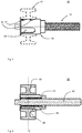
- FIG. 3 shows an ensemble of a ball screw 30, consisting of a threaded spindle 32 and a spindle nut 34, and the possible position for a power transmission element 39 (marked in phantom). It can be seen that in this embodiment both the openings 36, 37 for the ball deflection (s) would be covered by the force transmission element 39 as well as the recess 38.
- FIG. 4 an embodiment according to the invention is shown in cross section. It can be seen the ensemble of a ball screw 40, consisting of a threaded spindle 42 and a spindle nut 44. In the space between the threaded spindle and the spindle nut balls 43 are shown, the ball deflection is located outside the cutting plane. As can be seen at the lower edge of the spindle nut 44, the recess 48 (equivalent to recess 38 in FIG FIG. 3 ) is covered by the force transmission element 49. The force transmission element 49 fills at this point thus (depending on the design in part) a gap and thus partially compensates for the resulting loss of material. Also plotted is the section plane E, which in the FIGS. 5 to 9 is being used.
- FIGS. 5 to 9 show in cross section exactly those overlap region of the force transmission element 49, the positive and non-positive, the spindle nut 44 encloses.
- the location of a threaded spindle 42 is indicated.
- the proportions of threaded spindle 42, spindle nut 44 and power transmission element 49 are not to scale, the representation is to be understood as a sketch.
- FIG. 5 is the recess (corresponding to features 22, 23, 38, 48) designed as a flat, flat, recognizable in cross section as a circle segment flattening.
- This design can be achieved, for example, by planer grinding or milling, by a machining process or cold forming.
- the width b is determined by the deviation from the original outer contour.
- the maximum depth t of material removal is measured radially from the central axis to the outside, as the maximum difference between the radius of the original and the actual outer contour.
- the secant is not executed as a straight line, but as a radially inwardly curved floor.
- the width is measured as in FIG. 5 , the depth t is in turn defined as the maximum, radial deviation from the original outer contour.
- the material removal are realized as a wide trench with vertically radially sloping walls and a uniform depth t, whereby the bottom of the trench describes a circular arc at a constant distance from the central axis.
- FIG. 8 shows FIG. 8 where the floor is flattened in comparison flat.
- FIG. 9 shows a polygon profile (here hexagon), which deviates from the symmetry on one side. This would not have to be done parallel to a polygon side, but could also be done "over corner", which would lead to an irregular heptagon.
- this recess will have a flat bottom which, depending on the technical design, forms a peripheral, recessed edge to the lateral surface of the nut body ( FIG. 8 ) or in places flat, so without marginal stage, can open into the cylinder surface of the parent body (as in FIG. 5 ).
- the depth of the recess should be chosen so that the fatigue strength of the spindle nut body is not compromised. Depending on the wall thickness of the spindle nut body, the depth of the recess will therefore be a few tenths of a millimeter to a few millimeters.
Landscapes
- Engineering & Computer Science (AREA)
- General Engineering & Computer Science (AREA)
- Mechanical Engineering (AREA)
- Chemical & Material Sciences (AREA)
- Combustion & Propulsion (AREA)
- Transportation (AREA)
- Transmission Devices (AREA)
- Surgical Instruments (AREA)
- Motor Power Transmission Devices (AREA)
Priority Applications (5)
| Application Number | Priority Date | Filing Date | Title |
|---|---|---|---|
| EP18168493.7A EP3557096B1 (fr) | 2018-04-20 | 2018-04-20 | Méthode de compensation d'équilibrage et entraînement à vis à bille comprenant un élément de transmission de forces dimensionné avec cette méthode |
| ES18168493T ES2919562T3 (es) | 2018-04-20 | 2018-04-20 | Método de compensación del desequilibrio y accionamiento de husillo de bolas con elemento de transmisión de potencia según este método |
| PL18168493.7T PL3557096T3 (pl) | 2018-04-20 | 2018-04-20 | Sposób kompensacji niewyważenia i śruba pociągowa toczna z elementem przeniesienia siły według tego sposobu |
| CN201910315319.6A CN110388431B (zh) | 2018-04-20 | 2019-04-19 | 滚珠丝杠和用于补偿不平衡度的方法 |
| US16/389,242 US10948057B2 (en) | 2018-04-20 | 2019-04-19 | Ball screw drive with force transmission element and imbalance compensation |
Applications Claiming Priority (1)
| Application Number | Priority Date | Filing Date | Title |
|---|---|---|---|
| EP18168493.7A EP3557096B1 (fr) | 2018-04-20 | 2018-04-20 | Méthode de compensation d'équilibrage et entraînement à vis à bille comprenant un élément de transmission de forces dimensionné avec cette méthode |
Publications (2)
| Publication Number | Publication Date |
|---|---|
| EP3557096A1 true EP3557096A1 (fr) | 2019-10-23 |
| EP3557096B1 EP3557096B1 (fr) | 2022-04-13 |
Family
ID=62044565
Family Applications (1)
| Application Number | Title | Priority Date | Filing Date |
|---|---|---|---|
| EP18168493.7A Active EP3557096B1 (fr) | 2018-04-20 | 2018-04-20 | Méthode de compensation d'équilibrage et entraînement à vis à bille comprenant un élément de transmission de forces dimensionné avec cette méthode |
Country Status (5)
| Country | Link |
|---|---|
| US (1) | US10948057B2 (fr) |
| EP (1) | EP3557096B1 (fr) |
| CN (1) | CN110388431B (fr) |
| ES (1) | ES2919562T3 (fr) |
| PL (1) | PL3557096T3 (fr) |
Cited By (2)
| Publication number | Priority date | Publication date | Assignee | Title |
|---|---|---|---|---|
| US11473657B2 (en) * | 2020-03-25 | 2022-10-18 | Sfs Intec Holding Ag | Ball screw, spindle nut and method for producing a spindle nut |
| DE102023100756A1 (de) * | 2023-01-13 | 2024-07-18 | Schaeffler Technologies AG & Co. KG | Kugelgewindetrieb |
Families Citing this family (3)
| Publication number | Priority date | Publication date | Assignee | Title |
|---|---|---|---|---|
| JP2019039519A (ja) * | 2017-08-28 | 2019-03-14 | 株式会社ジェイテクト | ボールねじ装置、ボールねじ装置の製造方法及びボールねじ装置を備えたステアリング装置 |
| US11365791B1 (en) * | 2020-12-04 | 2022-06-21 | Schaeffler Technologies AG & Co. KG | Ball nut drive assembly |
| EP4361464A1 (fr) * | 2022-12-22 | 2024-05-01 | SFS Group International AG | Vis à billes et utilisation d'une vis à billes comme élément d'actionnement dans un système d'amplification de freinage ou comme élément d'actionnement dans un frein |
Citations (7)
| Publication number | Priority date | Publication date | Assignee | Title |
|---|---|---|---|---|
| US5809838A (en) * | 1995-05-30 | 1998-09-22 | Nsk Ltd. | Ball screw device with means for maintaining balance |
| JPH11344094A (ja) * | 1998-05-29 | 1999-12-14 | Sumitomo Heavy Ind Ltd | ナット回転用ボ−ルねじ |
| DE10022715A1 (de) * | 1999-05-10 | 2000-12-21 | Nsk Ltd | Kugelumlaufspindel |
| DE102008002627A1 (de) | 2008-06-25 | 2009-12-31 | Zf Lenksysteme Gmbh | Elektrische Servolenkung |
| JP2010048276A (ja) * | 2008-08-19 | 2010-03-04 | Ntn Corp | ボールねじ |
| DE102010046613A1 (de) * | 2010-09-25 | 2012-03-29 | Volkswagen Ag | Getriebe |
| EP2713078A1 (fr) * | 2012-09-28 | 2014-04-02 | Steering Solutions IP Holding Corporation | Poulie entraînée en résine de nylon |
Family Cites Families (12)
| Publication number | Priority date | Publication date | Assignee | Title |
|---|---|---|---|---|
| JP2976578B2 (ja) * | 1991-05-30 | 1999-11-10 | 株式会社日立製作所 | ロータのバランス修正方法 |
| DE102004040362A1 (de) * | 2004-08-20 | 2006-02-23 | Ina-Schaeffler Kg | Kugelgewindetrieb |
| US20110100143A1 (en) * | 2008-02-06 | 2011-05-05 | John Stanley Borza | Ball Screw and Nut Assembly |
| DE102009038086A1 (de) * | 2009-08-19 | 2011-02-24 | Schaeffler Technologies Gmbh & Co. Kg | Kugelgewindetrieb |
| DE102010025589A1 (de) * | 2010-06-29 | 2011-12-29 | Schaeffler Technologies Gmbh & Co. Kg | Kugelgewindetrieb |
| DE102010034697A1 (de) * | 2010-08-18 | 2012-02-23 | Volkswagen Ag | Kugelgewindetrieb |
| JP5897874B2 (ja) * | 2011-11-11 | 2016-04-06 | Ntn株式会社 | 電動リニアアクチュエータ |
| DE102012215395A1 (de) * | 2012-08-30 | 2014-03-06 | Schaeffler Technologies AG & Co. KG | Kugelgewindetrieb |
| DE102014219256B4 (de) * | 2014-09-24 | 2016-05-04 | Schaeffler Technologies AG & Co. KG | Kugelgewindetrieb |
| DE102015000487B3 (de) * | 2015-01-14 | 2016-02-18 | Fisw Steuerungstechnik Gmbh | Kugelgewindetrieb |
| DE102015214859B4 (de) * | 2015-08-04 | 2017-12-14 | Schaeffler Technologies AG & Co. KG | Kugelgewindetrieb |
| DE102016120249A1 (de) | 2016-10-24 | 2018-04-26 | Sfs Intec Holding Ag | Kugelgewindetrieb und verfahren zum ausgleich seiner unwucht |
-
2018
- 2018-04-20 EP EP18168493.7A patent/EP3557096B1/fr active Active
- 2018-04-20 PL PL18168493.7T patent/PL3557096T3/pl unknown
- 2018-04-20 ES ES18168493T patent/ES2919562T3/es active Active
-
2019
- 2019-04-19 CN CN201910315319.6A patent/CN110388431B/zh active Active
- 2019-04-19 US US16/389,242 patent/US10948057B2/en active Active
Patent Citations (7)
| Publication number | Priority date | Publication date | Assignee | Title |
|---|---|---|---|---|
| US5809838A (en) * | 1995-05-30 | 1998-09-22 | Nsk Ltd. | Ball screw device with means for maintaining balance |
| JPH11344094A (ja) * | 1998-05-29 | 1999-12-14 | Sumitomo Heavy Ind Ltd | ナット回転用ボ−ルねじ |
| DE10022715A1 (de) * | 1999-05-10 | 2000-12-21 | Nsk Ltd | Kugelumlaufspindel |
| DE102008002627A1 (de) | 2008-06-25 | 2009-12-31 | Zf Lenksysteme Gmbh | Elektrische Servolenkung |
| JP2010048276A (ja) * | 2008-08-19 | 2010-03-04 | Ntn Corp | ボールねじ |
| DE102010046613A1 (de) * | 2010-09-25 | 2012-03-29 | Volkswagen Ag | Getriebe |
| EP2713078A1 (fr) * | 2012-09-28 | 2014-04-02 | Steering Solutions IP Holding Corporation | Poulie entraînée en résine de nylon |
Cited By (2)
| Publication number | Priority date | Publication date | Assignee | Title |
|---|---|---|---|---|
| US11473657B2 (en) * | 2020-03-25 | 2022-10-18 | Sfs Intec Holding Ag | Ball screw, spindle nut and method for producing a spindle nut |
| DE102023100756A1 (de) * | 2023-01-13 | 2024-07-18 | Schaeffler Technologies AG & Co. KG | Kugelgewindetrieb |
Also Published As
| Publication number | Publication date |
|---|---|
| EP3557096B1 (fr) | 2022-04-13 |
| PL3557096T3 (pl) | 2022-09-19 |
| US20190323586A1 (en) | 2019-10-24 |
| CN110388431A (zh) | 2019-10-29 |
| CN110388431B (zh) | 2024-09-10 |
| US10948057B2 (en) | 2021-03-16 |
| ES2919562T3 (es) | 2022-07-27 |
Similar Documents
| Publication | Publication Date | Title |
|---|---|---|
| EP3557096B1 (fr) | Méthode de compensation d'équilibrage et entraînement à vis à bille comprenant un élément de transmission de forces dimensionné avec cette méthode | |
| EP4038271B1 (fr) | Pale de rotor d'éolienne et procédé de liaison de deux segments de pale de rotor | |
| DE69502550T2 (de) | Profilanpassung für Vielwalzengerüste | |
| EP2603340B1 (fr) | Porte-outil | |
| DE3916314A1 (de) | Verfahren und vorrichtung zum feststellen der erforderlichen anstellung von waelzlagern in getrieben | |
| EP3909710A1 (fr) | Tête de fraisage, machine de traitement et procédé de fonctionnement d'une machine de traitement | |
| WO2015106895A1 (fr) | Axe de satellite à bride vissable | |
| EP1754030B1 (fr) | Securite antisurcharge pour element dynamometrique | |
| EP2685615A1 (fr) | Equilibrage amélioré d'un rotor | |
| EP0939248A2 (fr) | Dispositif d'engrenage avec denture extérieure | |
| EP2435721A1 (fr) | Liaison arbre-moyeu à profil polygonal | |
| DE69515181T2 (de) | Exzentergetriebe | |
| AT521959A4 (de) | Zahnrad | |
| EP2359029B1 (fr) | Transmission | |
| DE102020003346B3 (de) | Umfangsstabmesserkopf | |
| EP3312473B1 (fr) | Vis à billes et procédé de compensation de son balourd | |
| DE3708746C1 (de) | Kupplungsanordnung zum drehfesten biegesteifen Verbinden von miteinander zu verbindenden Teilen | |
| DE602005006042T2 (de) | Vorrichtung zur Umwandlung einer rotierenden Bewegung in eine lineare Bewegung. | |
| DE102008036743A1 (de) | Getriebe mit Slots | |
| DE102019212221A1 (de) | Wellgetriebe | |
| DE102019212220B4 (de) | Wellgetriebe | |
| DE20320068U1 (de) | Verbindung zweier Maschinenteile | |
| DE102019104125B4 (de) | Kugelgewindetrieb mit Verdrehsicherung | |
| WO2022058431A1 (fr) | Coussinet élastomère, ensemble coussinet et palier d'éolienne pour éoliennes | |
| DE19509768C2 (de) | Lager |
Legal Events
| Date | Code | Title | Description |
|---|---|---|---|
| PUAI | Public reference made under article 153(3) epc to a published international application that has entered the european phase |
Free format text: ORIGINAL CODE: 0009012 |
|
| STAA | Information on the status of an ep patent application or granted ep patent |
Free format text: STATUS: THE APPLICATION HAS BEEN PUBLISHED |
|
| AK | Designated contracting states |
Kind code of ref document: A1 Designated state(s): AL AT BE BG CH CY CZ DE DK EE ES FI FR GB GR HR HU IE IS IT LI LT LU LV MC MK MT NL NO PL PT RO RS SE SI SK SM TR |
|
| AX | Request for extension of the european patent |
Extension state: BA ME |
|
| STAA | Information on the status of an ep patent application or granted ep patent |
Free format text: STATUS: REQUEST FOR EXAMINATION WAS MADE |
|
| 17P | Request for examination filed |
Effective date: 20200423 |
|
| RBV | Designated contracting states (corrected) |
Designated state(s): AL AT BE BG CH CY CZ DE DK EE ES FI FR GB GR HR HU IE IS IT LI LT LU LV MC MK MT NL NO PL PT RO RS SE SI SK SM TR |
|
| RIC1 | Information provided on ipc code assigned before grant |
Ipc: F16H 25/20 20060101ALN20211019BHEP Ipc: B62D 5/04 20060101ALN20211019BHEP Ipc: F16H 25/24 20060101ALI20211019BHEP Ipc: F16H 25/22 20060101AFI20211019BHEP |
|
| GRAP | Despatch of communication of intention to grant a patent |
Free format text: ORIGINAL CODE: EPIDOSNIGR1 |
|
| STAA | Information on the status of an ep patent application or granted ep patent |
Free format text: STATUS: GRANT OF PATENT IS INTENDED |
|
| RIC1 | Information provided on ipc code assigned before grant |
Ipc: F16H 25/20 20060101ALN20211202BHEP Ipc: B62D 5/04 20060101ALN20211202BHEP Ipc: F16H 25/24 20060101ALI20211202BHEP Ipc: F16H 25/22 20060101AFI20211202BHEP |
|
| INTG | Intention to grant announced |
Effective date: 20220105 |
|
| GRAS | Grant fee paid |
Free format text: ORIGINAL CODE: EPIDOSNIGR3 |
|
| GRAA | (expected) grant |
Free format text: ORIGINAL CODE: 0009210 |
|
| STAA | Information on the status of an ep patent application or granted ep patent |
Free format text: STATUS: THE PATENT HAS BEEN GRANTED |
|
| RAP3 | Party data changed (applicant data changed or rights of an application transferred) |
Owner name: SFS GROUP INTERNATIONAL AG |
|
| AK | Designated contracting states |
Kind code of ref document: B1 Designated state(s): AL AT BE BG CH CY CZ DE DK EE ES FI FR GB GR HR HU IE IS IT LI LT LU LV MC MK MT NL NO PL PT RO RS SE SI SK SM TR |
|
| REG | Reference to a national code |
Ref country code: GB Ref legal event code: FG4D Free format text: NOT ENGLISH |
|
| REG | Reference to a national code |
Ref country code: CH Ref legal event code: EP |
|
| REG | Reference to a national code |
Ref country code: DE Ref legal event code: R096 Ref document number: 502018009370 Country of ref document: DE |
|
| REG | Reference to a national code |
Ref country code: IE Ref legal event code: FG4D Free format text: LANGUAGE OF EP DOCUMENT: GERMAN |
|
| REG | Reference to a national code |
Ref country code: AT Ref legal event code: REF Ref document number: 1483641 Country of ref document: AT Kind code of ref document: T Effective date: 20220515 |
|
| REG | Reference to a national code |
Ref country code: RO Ref legal event code: EPE |
|
| REG | Reference to a national code |
Ref country code: SE Ref legal event code: TRGR |
|
| REG | Reference to a national code |
Ref country code: ES Ref legal event code: FG2A Ref document number: 2919562 Country of ref document: ES Kind code of ref document: T3 Effective date: 20220727 |
|
| REG | Reference to a national code |
Ref country code: LT Ref legal event code: MG9D |
|
| REG | Reference to a national code |
Ref country code: NL Ref legal event code: MP Effective date: 20220413 |
|
| PG25 | Lapsed in a contracting state [announced via postgrant information from national office to epo] |
Ref country code: NL Free format text: LAPSE BECAUSE OF FAILURE TO SUBMIT A TRANSLATION OF THE DESCRIPTION OR TO PAY THE FEE WITHIN THE PRESCRIBED TIME-LIMIT Effective date: 20220413 |
|
| PG25 | Lapsed in a contracting state [announced via postgrant information from national office to epo] |
Ref country code: PT Free format text: LAPSE BECAUSE OF FAILURE TO SUBMIT A TRANSLATION OF THE DESCRIPTION OR TO PAY THE FEE WITHIN THE PRESCRIBED TIME-LIMIT Effective date: 20220816 Ref country code: NO Free format text: LAPSE BECAUSE OF FAILURE TO SUBMIT A TRANSLATION OF THE DESCRIPTION OR TO PAY THE FEE WITHIN THE PRESCRIBED TIME-LIMIT Effective date: 20220713 Ref country code: LT Free format text: LAPSE BECAUSE OF FAILURE TO SUBMIT A TRANSLATION OF THE DESCRIPTION OR TO PAY THE FEE WITHIN THE PRESCRIBED TIME-LIMIT Effective date: 20220413 Ref country code: HR Free format text: LAPSE BECAUSE OF FAILURE TO SUBMIT A TRANSLATION OF THE DESCRIPTION OR TO PAY THE FEE WITHIN THE PRESCRIBED TIME-LIMIT Effective date: 20220413 Ref country code: GR Free format text: LAPSE BECAUSE OF FAILURE TO SUBMIT A TRANSLATION OF THE DESCRIPTION OR TO PAY THE FEE WITHIN THE PRESCRIBED TIME-LIMIT Effective date: 20220714 Ref country code: FI Free format text: LAPSE BECAUSE OF FAILURE TO SUBMIT A TRANSLATION OF THE DESCRIPTION OR TO PAY THE FEE WITHIN THE PRESCRIBED TIME-LIMIT Effective date: 20220413 Ref country code: BG Free format text: LAPSE BECAUSE OF FAILURE TO SUBMIT A TRANSLATION OF THE DESCRIPTION OR TO PAY THE FEE WITHIN THE PRESCRIBED TIME-LIMIT Effective date: 20220713 |
|
| PG25 | Lapsed in a contracting state [announced via postgrant information from national office to epo] |
Ref country code: RS Free format text: LAPSE BECAUSE OF FAILURE TO SUBMIT A TRANSLATION OF THE DESCRIPTION OR TO PAY THE FEE WITHIN THE PRESCRIBED TIME-LIMIT Effective date: 20220413 Ref country code: LV Free format text: LAPSE BECAUSE OF FAILURE TO SUBMIT A TRANSLATION OF THE DESCRIPTION OR TO PAY THE FEE WITHIN THE PRESCRIBED TIME-LIMIT Effective date: 20220413 Ref country code: IS Free format text: LAPSE BECAUSE OF FAILURE TO SUBMIT A TRANSLATION OF THE DESCRIPTION OR TO PAY THE FEE WITHIN THE PRESCRIBED TIME-LIMIT Effective date: 20220813 |
|
| REG | Reference to a national code |
Ref country code: BE Ref legal event code: MM Effective date: 20220430 |
|
| REG | Reference to a national code |
Ref country code: DE Ref legal event code: R097 Ref document number: 502018009370 Country of ref document: DE |
|
| PG25 | Lapsed in a contracting state [announced via postgrant information from national office to epo] |
Ref country code: SM Free format text: LAPSE BECAUSE OF FAILURE TO SUBMIT A TRANSLATION OF THE DESCRIPTION OR TO PAY THE FEE WITHIN THE PRESCRIBED TIME-LIMIT Effective date: 20220413 Ref country code: SK Free format text: LAPSE BECAUSE OF FAILURE TO SUBMIT A TRANSLATION OF THE DESCRIPTION OR TO PAY THE FEE WITHIN THE PRESCRIBED TIME-LIMIT Effective date: 20220413 Ref country code: MC Free format text: LAPSE BECAUSE OF FAILURE TO SUBMIT A TRANSLATION OF THE DESCRIPTION OR TO PAY THE FEE WITHIN THE PRESCRIBED TIME-LIMIT Effective date: 20220413 Ref country code: LU Free format text: LAPSE BECAUSE OF NON-PAYMENT OF DUE FEES Effective date: 20220420 Ref country code: EE Free format text: LAPSE BECAUSE OF FAILURE TO SUBMIT A TRANSLATION OF THE DESCRIPTION OR TO PAY THE FEE WITHIN THE PRESCRIBED TIME-LIMIT Effective date: 20220413 Ref country code: DK Free format text: LAPSE BECAUSE OF FAILURE TO SUBMIT A TRANSLATION OF THE DESCRIPTION OR TO PAY THE FEE WITHIN THE PRESCRIBED TIME-LIMIT Effective date: 20220413 |
|
| PLBE | No opposition filed within time limit |
Free format text: ORIGINAL CODE: 0009261 |
|
| STAA | Information on the status of an ep patent application or granted ep patent |
Free format text: STATUS: NO OPPOSITION FILED WITHIN TIME LIMIT |
|
| PG25 | Lapsed in a contracting state [announced via postgrant information from national office to epo] |
Ref country code: BE Free format text: LAPSE BECAUSE OF NON-PAYMENT OF DUE FEES Effective date: 20220430 |
|
| 26N | No opposition filed |
Effective date: 20230116 |
|
| PG25 | Lapsed in a contracting state [announced via postgrant information from national office to epo] |
Ref country code: AL Free format text: LAPSE BECAUSE OF FAILURE TO SUBMIT A TRANSLATION OF THE DESCRIPTION OR TO PAY THE FEE WITHIN THE PRESCRIBED TIME-LIMIT Effective date: 20220413 |
|
| PG25 | Lapsed in a contracting state [announced via postgrant information from national office to epo] |
Ref country code: IE Free format text: LAPSE BECAUSE OF NON-PAYMENT OF DUE FEES Effective date: 20220420 |
|
| PG25 | Lapsed in a contracting state [announced via postgrant information from national office to epo] |
Ref country code: SI Free format text: LAPSE BECAUSE OF FAILURE TO SUBMIT A TRANSLATION OF THE DESCRIPTION OR TO PAY THE FEE WITHIN THE PRESCRIBED TIME-LIMIT Effective date: 20220413 |
|
| P01 | Opt-out of the competence of the unified patent court (upc) registered |
Effective date: 20230622 |
|
| PG25 | Lapsed in a contracting state [announced via postgrant information from national office to epo] |
Ref country code: HU Free format text: LAPSE BECAUSE OF FAILURE TO SUBMIT A TRANSLATION OF THE DESCRIPTION OR TO PAY THE FEE WITHIN THE PRESCRIBED TIME-LIMIT; INVALID AB INITIO Effective date: 20180420 |
|
| PG25 | Lapsed in a contracting state [announced via postgrant information from national office to epo] |
Ref country code: MK Free format text: LAPSE BECAUSE OF FAILURE TO SUBMIT A TRANSLATION OF THE DESCRIPTION OR TO PAY THE FEE WITHIN THE PRESCRIBED TIME-LIMIT Effective date: 20220413 Ref country code: CY Free format text: LAPSE BECAUSE OF FAILURE TO SUBMIT A TRANSLATION OF THE DESCRIPTION OR TO PAY THE FEE WITHIN THE PRESCRIBED TIME-LIMIT Effective date: 20220413 |
|
| PG25 | Lapsed in a contracting state [announced via postgrant information from national office to epo] |
Ref country code: TR Free format text: LAPSE BECAUSE OF FAILURE TO SUBMIT A TRANSLATION OF THE DESCRIPTION OR TO PAY THE FEE WITHIN THE PRESCRIBED TIME-LIMIT Effective date: 20220413 |
|
| PG25 | Lapsed in a contracting state [announced via postgrant information from national office to epo] |
Ref country code: MT Free format text: LAPSE BECAUSE OF FAILURE TO SUBMIT A TRANSLATION OF THE DESCRIPTION OR TO PAY THE FEE WITHIN THE PRESCRIBED TIME-LIMIT Effective date: 20220413 |
|
| PG25 | Lapsed in a contracting state [announced via postgrant information from national office to epo] |
Ref country code: BG Free format text: LAPSE BECAUSE OF FAILURE TO SUBMIT A TRANSLATION OF THE DESCRIPTION OR TO PAY THE FEE WITHIN THE PRESCRIBED TIME-LIMIT Effective date: 20220413 |
|
| PG25 | Lapsed in a contracting state [announced via postgrant information from national office to epo] |
Ref country code: BG Free format text: LAPSE BECAUSE OF FAILURE TO SUBMIT A TRANSLATION OF THE DESCRIPTION OR TO PAY THE FEE WITHIN THE PRESCRIBED TIME-LIMIT Effective date: 20220413 |
|
| PGFP | Annual fee paid to national office [announced via postgrant information from national office to epo] |
Ref country code: PL Payment date: 20250408 Year of fee payment: 8 Ref country code: DE Payment date: 20250417 Year of fee payment: 8 |
|
| PGFP | Annual fee paid to national office [announced via postgrant information from national office to epo] |
Ref country code: ES Payment date: 20250519 Year of fee payment: 8 Ref country code: GB Payment date: 20250423 Year of fee payment: 8 |
|
| PGFP | Annual fee paid to national office [announced via postgrant information from national office to epo] |
Ref country code: IT Payment date: 20250430 Year of fee payment: 8 |
|
| PGFP | Annual fee paid to national office [announced via postgrant information from national office to epo] |
Ref country code: FR Payment date: 20250425 Year of fee payment: 8 |
|
| PGFP | Annual fee paid to national office [announced via postgrant information from national office to epo] |
Ref country code: CH Payment date: 20250501 Year of fee payment: 8 |
|
| PGFP | Annual fee paid to national office [announced via postgrant information from national office to epo] |
Ref country code: RO Payment date: 20250414 Year of fee payment: 8 Ref country code: AT Payment date: 20250416 Year of fee payment: 8 |
|
| PGFP | Annual fee paid to national office [announced via postgrant information from national office to epo] |
Ref country code: CZ Payment date: 20250404 Year of fee payment: 8 |
|
| PGFP | Annual fee paid to national office [announced via postgrant information from national office to epo] |
Ref country code: SE Payment date: 20250423 Year of fee payment: 8 |