EP3557552B1 - Verfahren und vorrichtung zur omnidirektionalen und sabotagesicheren manipulationsdetektion - Google Patents
Verfahren und vorrichtung zur omnidirektionalen und sabotagesicheren manipulationsdetektion Download PDFInfo
- Publication number
- EP3557552B1 EP3557552B1 EP19168760.7A EP19168760A EP3557552B1 EP 3557552 B1 EP3557552 B1 EP 3557552B1 EP 19168760 A EP19168760 A EP 19168760A EP 3557552 B1 EP3557552 B1 EP 3557552B1
- Authority
- EP
- European Patent Office
- Prior art keywords
- security device
- magnetic field
- mounting bracket
- magnetometer
- voltages
- Prior art date
- Legal status (The legal status is an assumption and is not a legal conclusion. Google has not performed a legal analysis and makes no representation as to the accuracy of the status listed.)
- Active
Links
Images




Classifications
-
- G—PHYSICS
- G08—SIGNALLING
- G08B—SIGNALLING SYSTEMS, e.g. PERSONAL CALLING SYSTEMS; ORDER TELEGRAPHS; ALARM SYSTEMS
- G08B13/00—Burglar, theft or intruder alarms
- G08B13/22—Electrical actuation
- G08B13/24—Electrical actuation by interference with electromagnetic field distribution
-
- G—PHYSICS
- G08—SIGNALLING
- G08B—SIGNALLING SYSTEMS, e.g. PERSONAL CALLING SYSTEMS; ORDER TELEGRAPHS; ALARM SYSTEMS
- G08B29/00—Checking or monitoring of signalling or alarm systems; Prevention or correction of operating errors, e.g. preventing unauthorised operation
- G08B29/02—Monitoring continuously signalling or alarm systems
- G08B29/04—Monitoring of the detection circuits
- G08B29/046—Monitoring of the detection circuits prevention of tampering with detection circuits
-
- G—PHYSICS
- G08—SIGNALLING
- G08B—SIGNALLING SYSTEMS, e.g. PERSONAL CALLING SYSTEMS; ORDER TELEGRAPHS; ALARM SYSTEMS
- G08B13/00—Burglar, theft or intruder alarms
- G08B13/18—Actuation by interference with heat, light, or radiation of shorter wavelength; Actuation by intruding sources of heat, light, or radiation of shorter wavelength
- G08B13/189—Actuation by interference with heat, light, or radiation of shorter wavelength; Actuation by intruding sources of heat, light, or radiation of shorter wavelength using passive radiation detection systems
- G08B13/194—Actuation by interference with heat, light, or radiation of shorter wavelength; Actuation by intruding sources of heat, light, or radiation of shorter wavelength using passive radiation detection systems using image scanning and comparing systems
- G08B13/196—Actuation by interference with heat, light, or radiation of shorter wavelength; Actuation by intruding sources of heat, light, or radiation of shorter wavelength using passive radiation detection systems using image scanning and comparing systems using television cameras
- G08B13/19617—Surveillance camera constructional details
- G08B13/19632—Camera support structures, e.g. attachment means, poles
-
- G—PHYSICS
- G08—SIGNALLING
- G08B—SIGNALLING SYSTEMS, e.g. PERSONAL CALLING SYSTEMS; ORDER TELEGRAPHS; ALARM SYSTEMS
- G08B25/00—Alarm systems in which the location of the alarm condition is signalled to a central station, e.g. fire or police telegraphic systems
- G08B25/01—Alarm systems in which the location of the alarm condition is signalled to a central station, e.g. fire or police telegraphic systems characterised by the transmission medium
- G08B25/10—Alarm systems in which the location of the alarm condition is signalled to a central station, e.g. fire or police telegraphic systems characterised by the transmission medium using wireless transmission systems
-
- H—ELECTRICITY
- H04—ELECTRIC COMMUNICATION TECHNIQUE
- H04N—PICTORIAL COMMUNICATION, e.g. TELEVISION
- H04N7/00—Television systems
- H04N7/18—Closed-circuit television [CCTV] systems, i.e. systems in which the video signal is not broadcast
Definitions
- determining the changes in the magnetic field based upon the voltages obtained from the magnetometer comprises storing a reference voltage that represents the magnetic field at the security device for an initial position of the security device within the mounting bracket, and comparing the voltages obtained from the magnetometer to the reference voltage to determine whether the obtained voltages have changed as compared to the reference voltage.
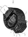
- the housing 40 includes a front portion 39, a middle portion 29, and a back portion 19.
- the middle portion 29 fastens to the front portion 39 via screws 31.
- the back portion 19 attaches to the middle portion 29 via a snap fit, in one example.
- These portions are typically made from plastic or other lightweight material that can be formed/molded to meet design and assembly considerations.
- Batteries 36 are located within the back portion 19 and the middle portion 29 of the housing 40.
- the batteries 36 provide a source of input power to the sensor module 60, the anti-tampering system, and the motion sensor system 21.
- the batteries 36 are attached to a rear side of the middle portion 29 of the housing 40, via a pull tab 37.
- the back portion 19 is a removable cover for the batteries 36.
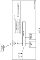
- Fig. 6 is a block diagram that illustrates various components of the sensor module 60.
- step 706 the controller 50 obtains another voltage from the magnetic field sensor 54 of the magnetometer 30.
- the controller 50 compares the obtained voltage to the reference voltage 129.
- the controller 50 polls the magnetic field sensor 54 on the order of 100 milliseconds to obtain its voltage.
- the polling interval is as large as 1 to 5 seconds to conserve the batteries 36.
- step 712 the controller 50 determines if the obtained voltage is less than the minimum voltage 109. If the voltage is less than the minimum voltage 109, the method transitions to step 714. Otherwise, the method transitions to the beginning of step 706 to obtain a new voltage from the magnetic field sensor 54.
Landscapes
- Physics & Mathematics (AREA)
- General Physics & Mathematics (AREA)
- Engineering & Computer Science (AREA)
- Multimedia (AREA)
- Signal Processing (AREA)
- Electromagnetism (AREA)
- Computer Security & Cryptography (AREA)
- Computer Networks & Wireless Communication (AREA)
- Business, Economics & Management (AREA)
- Emergency Management (AREA)
- Alarm Systems (AREA)
- Burglar Alarm Systems (AREA)
Claims (15)
- Sicherheitsvorrichtungsanordnung (10), umfassend:eine Montagehalterung (14);eine Sicherheitsvorrichtung (12), die in der Montagehalterung (14) sitzt und um eine Ausrichtungsachse drehbar ist;einen an der Montagehalterung befestigten Permanentmagneten (28);ein in der Sicherheitsvorrichtung (12) enthaltenes Magnetometer (30) zum Erkennen eines durch den Permanentmagneten erzeugten Magnetfeldes; undeine Steuervorrichtung (50), die Änderungen des durch das Magnetometer (30) erkannten Magnetfeldes bestimmt, die eine Drehung der Sicherheitsvorrichtung (12) innerhalb der Montagehalterung (14) anzeigen,wobei die Steuervorrichtung (50) als Reaktion darauf, dass die bestimmten Änderungen des Magnetfelds außerhalb eines zulässigen Bereichs liegen, bestimmt, dass die Drehung der Sicherheitsvorrichtung (12) innerhalb der Montagehalterung (14) mit einer Manipulation der Sicherheitsvorrichtung (12) verknüpft ist.
- Sicherheitsvorrichtungsanordnung (10) gemäß Anspruch 1, wobei die Montagehalterung (14) einen Körper (68) und einen sich von dem Körper (68) erstreckenden oberen Abschnitt enthält, und wobei die Ausrichtungsachse (39) durch die Mitte des oberen Abschnitts (38) der Montagehalterung (14) und entlang des Körpers (68) der Montagehalterung (14) verläuft.
- Sicherheitsvorrichtungsanordnung (10) gemäß Anspruch 2, wobei die Sicherheitsvorrichtung (12) ein abnehmbar mit der Montagehalterung (14) verbindbares Gehäuse (40) enthält und wobei, wenn die Sicherheitsvorrichtung (12) vollständig in der Montagehalterung (14) sitzt, die Ausrichtungsachse (39) durch die Mitte des Gehäuses (40) der Sicherheitsvorrichtung (12) verläuft.
- Sicherheitsvorrichtungsanordnung (10) gemäß einem der vorhergehenden Ansprüche, wobei die Montagehalterung (14) enthält:einen an einer Fläche befestigten Körper (68) und einen in dem Körper enthalten Auswerfer (58),wobei der Auswerfer (58) abnehmbar an dem Körper (68) angebracht ist und an einer gleichen Fläche wie der Körper (68) befestigt ist, und wobei der Permanentmagnet (28) an dem Auswerfer (58) angebracht ist.
- Sicherheitsvorrichtungsanordnung (10) gemäß einem der vorhergehenden Ansprüche, wobei die Sicherheitsvorrichtung (12) ein Bewegungsdetektor (12) oder eine Überwachungskamera ist.
- Sicherheitsvorrichtungsanordnung (10) gemäß einem der vorhergehenden Ansprüche, wobei die Sicherheitsvorrichtung (12) eine Branderkennungsvorrichtung umfasst.
- Sicherheitsvorrichtungsanordnung (10) gemäß einem der vorhergehenden Ansprüche, wobei das Magnetometer (30) einen Hall-Effekt-Sensor und einen ferromagnetischen Kern (18) enthält.
- Sicherheitsvorrichtungsanordnung (10) gemäß einem der vorhergehenden Ansprüche, wobei das Magnetometer (30) einen zeitlichen Spannungsverlauf erzeugt, der das erkannte Magnetfeld des Permanentmagneten (28) repräsentiert, und wobei die Steuervorrichtung (50) die Spannungen aus dem Magnetometer (30) erhält und die Änderungen in dem Magnetfeld, die die Drehung der Sicherheitsvorrichtung (12) anzeigen, basierend auf den aus dem Magnetometer (30) erhaltenen Spannungen bestimmt.
- Sicherheitsvorrichtungsanordnung (10) gemäß Anspruch 8, wobei die Steuervorrichtung (50) das erkannte Magnetfeld repräsentierende Spannungen speichert und wobei die Steuervorrichtung (50) bestimmt, dass die die Drehung der Sicherheitsvorrichtung (12) anzeigenden Änderungen des Magnetfelds mit der Manipulation der Sicherheitsvorrichtung (12) verknüpft sind, wenn durch das Magnetometer (30) erhaltene aktuelle Spannungen die Änderungen anzeigen.
- Sicherheitsvorrichtungsanordnung (10) gemäß einem der vorhergehenden Ansprüche, wobei die Sicherheitsvorrichtung (12) ein Gehäuse (40) enthält, das im Allgemeinen zylindrisch ist.
- Verfahren zum Erkennen von Manipulation an einer Sicherheitsvorrichtung (12), umfassend:Erkennen eines durch einen an der Halterung (14) angebrachten Permanentmagneten (28) erzeugten Magnetfeldes durch ein Magnetometer (30), das in der Sicherheitsvorrichtung (12) enthalten ist, die in einer Montagehalterung (14) sitzt und um eine Ausrichtungsachse drehbar ist;Bestimmen von Änderungen in dem durch das Magnetometer (30) erkannten Magnetfeld, die eine Drehung der Sicherheitsvorrichtung (12) innerhalb der Montagehalterung (14) anzeigen; und als Reaktion darauf, dass die bestimmten Änderungen in dem Magnetfeld außerhalb eines zulässigen Bereichs liegen, Bestimmen, dass die Drehung der Sicherheitsvorrichtung (12) innerhalb der Montagehalterung (14) mit der Manipulation an der Sicherheitsvorrichtung (12) verknüpft ist.
- Verfahren gemäß Anspruch 11, wobei die Sicherheitsvorrichtung (12) ein abnehmbar mit der Montagehalterung (14) verbindbares Gehäuse (40) enthält und wobei, wenn die Sicherheitsvorrichtung (12) vollständig in der Montagehalterung (14) sitzt, die Ausrichtungsachse (39) durch die Mitte des Gehäuses (40) der Sicherheitsvorrichtung (12) verläuft.
- Verfahren gemäß Anspruch 11, wobei das Bestimmen der Änderungen des die Drehung der Sicherheitsvorrichtung (12) innerhalb der Montagehalterung (14) anzeigenden Magnetfeldes umfasst:Erzeugen eines das Magnetfeld repräsentierenden zeitlichen Spannungsverlaufs durch das in der Sicherheitsvorrichtung (12) enthaltene Magnetometer (30) ;Erhalten von aktuellen Spannungen aus dem Magnetometer (30); undBestimmen der Änderungen des Magnetfeldes basierend auf den aus dem Magnetometer (30) erhaltenen aktuellen Spannungen.
- Verfahren gemäß Anspruch 13, wobei das Bestimmen der Änderungen des Magnetfeldes basierend auf den aus dem Magnetometer (30) erhaltenen aktuellen Spannungen umfasst:Speichern von Referenzspannungen, die das Magnetfeld an der Sicherheitsvorrichtung (12) für eine Anfangsstellung der Sicherheitsvorrichtung (12) repräsentieren; undVergleichen der aus dem Magnetometer (30) erhaltenen aktuellen Spannungen mit den Referenzspannungen, um zu bestimmen, ob sich die aktuellen Spannungen im Vergleich zu den Referenzspannungen geändert haben.
- Verfahren gemäß Anspruch 14, wobei das Bestimmen, dass die aktuellen Spannungen die Manipulation der Sicherheitsvorrichtung (12) anzeigen, ferner als Reaktion erfolgt auf:
Bestimmen, dass die aktuellen Spannungen größer als eine Maximalspannung sind, die einen Maximalwert des Magnetfeldes repräsentiert, oder dass die aktuellen Spannungen kleiner als eine Minimalspannung sind, die einen Minimalwert des Magnetfeldes repräsentiert.
Applications Claiming Priority (1)
| Application Number | Priority Date | Filing Date | Title |
|---|---|---|---|
| US15/953,624 US10565842B2 (en) | 2018-04-16 | 2018-04-16 | Method and device for omnidirectional and anti-sabotage anti-tampering detection |
Publications (2)
| Publication Number | Publication Date |
|---|---|
| EP3557552A1 EP3557552A1 (de) | 2019-10-23 |
| EP3557552B1 true EP3557552B1 (de) | 2021-06-09 |
Family
ID=66105259
Family Applications (1)
| Application Number | Title | Priority Date | Filing Date |
|---|---|---|---|
| EP19168760.7A Active EP3557552B1 (de) | 2018-04-16 | 2019-04-11 | Verfahren und vorrichtung zur omnidirektionalen und sabotagesicheren manipulationsdetektion |
Country Status (2)
| Country | Link |
|---|---|
| US (1) | US10565842B2 (de) |
| EP (1) | EP3557552B1 (de) |
Cited By (1)
| Publication number | Priority date | Publication date | Assignee | Title |
|---|---|---|---|---|
| EP4144193A1 (de) * | 2020-04-29 | 2023-03-08 | Essence Security International Ltd. | Sicherheitsvorrichtung |
Families Citing this family (8)
| Publication number | Priority date | Publication date | Assignee | Title |
|---|---|---|---|---|
| US10755554B2 (en) * | 2018-09-28 | 2020-08-25 | Nortek Security & Control Llc | Vector magnetic tamper detection for sensors |
| WO2020099521A1 (en) * | 2018-11-13 | 2020-05-22 | Tyco Fire & Security Gmbh | Contact sensor with masking detection feature |
| US12078694B2 (en) | 2019-07-30 | 2024-09-03 | Google Llc | Sensor-based tamper detection for mounted electronic devices |
| EP3819887A1 (de) * | 2019-11-07 | 2021-05-12 | Heim, Mark | Gefahrenmelder und verfahren zum betreiben eines gefahrenmelders |
| ES2976588T3 (es) * | 2020-01-10 | 2024-08-05 | Verisure Sarl | Un conjunto de alarma |
| DE102020201959B4 (de) * | 2020-02-17 | 2021-10-28 | Continental Automotive Gmbh | Magnetfeldsensor mit einem Gerätegehäuse |
| US11852957B2 (en) | 2020-09-22 | 2023-12-26 | Google Llc | Thermal-control system for a security camera and associated security camera |
| US20250109971A1 (en) * | 2023-10-02 | 2025-04-03 | Carrier Corporation | Tamper-proof sensor assembly |
Family Cites Families (12)
| Publication number | Priority date | Publication date | Assignee | Title |
|---|---|---|---|---|
| EP1227452A1 (de) | 2001-01-19 | 2002-07-31 | Siemens Building Technologies AG | Sicherheitssystem und Gefahrenmelder zur Überwachung von Gefahrenkenngrössen |
| WO2003019492A1 (en) * | 2001-08-23 | 2003-03-06 | Johnny Pollard | Fire detection system |
| US7388484B2 (en) * | 2005-08-16 | 2008-06-17 | Honeywell International Inc. | Conductive tamper switch for security devices |
| US7528717B2 (en) * | 2006-06-14 | 2009-05-05 | Honeywell International Inc. | Tamper detection mechanism for blind installation of circular sensors |
| US7728720B2 (en) * | 2006-07-28 | 2010-06-01 | Deere & Company | System and method for monitoring a status of a member of a vehicle |
| US7667600B2 (en) | 2006-12-16 | 2010-02-23 | Roc2Loc, Inc. | Methods and apparatus for security device removal detection |
| EP2269177A4 (de) * | 2008-03-24 | 2014-01-22 | Strata Proximity Systems Llc | Einstellung eines elektromagnetischen felds zur proximitätsdetektion |
| GB2487560B (en) | 2011-01-26 | 2013-09-04 | Thorn Security | Fire detector unit |
| WO2014047078A1 (en) * | 2012-09-18 | 2014-03-27 | Vootner Goushe Llc | Sensor system for protection of artworks and other valuable objects |
| US20170228603A1 (en) * | 2013-03-15 | 2017-08-10 | August Home, Inc. | Door lock system with wide view camera |
| US10051347B2 (en) * | 2013-08-02 | 2018-08-14 | Stephen Hollis | Displacement sensor |
| US9739637B2 (en) * | 2014-10-31 | 2017-08-22 | Allegro Microsystems, Llc | Magnetic field motion sensor and related techniques |
-
2018
- 2018-04-16 US US15/953,624 patent/US10565842B2/en active Active
-
2019
- 2019-04-11 EP EP19168760.7A patent/EP3557552B1/de active Active
Non-Patent Citations (1)
| Title |
|---|
| None * |
Cited By (1)
| Publication number | Priority date | Publication date | Assignee | Title |
|---|---|---|---|---|
| EP4144193A1 (de) * | 2020-04-29 | 2023-03-08 | Essence Security International Ltd. | Sicherheitsvorrichtung |
Also Published As
| Publication number | Publication date |
|---|---|
| US20190318595A1 (en) | 2019-10-17 |
| US10565842B2 (en) | 2020-02-18 |
| EP3557552A1 (de) | 2019-10-23 |
Similar Documents
| Publication | Publication Date | Title |
|---|---|---|
| EP3557552B1 (de) | Verfahren und vorrichtung zur omnidirektionalen und sabotagesicheren manipulationsdetektion | |
| EP3082115B1 (de) | Geführtes installationsfeedback für einen öffnungssensor | |
| EP3665663B1 (de) | Nah-fern-sicherheitssensor | |
| US12474420B2 (en) | Sensor-based tamper detection for mounted electronic devices | |
| US7187280B2 (en) | Alarm system with thin profile | |
| US9947189B2 (en) | Home automation device for monitoring the movement of a swinging wing and method for enhancing the reliability of such a device | |
| US20160323118A1 (en) | Self-Identifying, Multi-Function Sensor Device and Monitoring System Including Same | |
| EP3625780B1 (de) | System und verfahren zum automatischen deaktivieren eines eindringungserkennungssystems | |
| EP3249623B1 (de) | Sensor und verfahren zur erfassung eines eindringens | |
| EP3142089B1 (de) | Benachrichtigung bezüglich einer system-scharfschaltung auf basis von einer ble-position | |
| CN207409080U (zh) | 一种门磁装置 | |
| JPH1061273A (ja) | 引戸用見張番システム | |
| US20080031607A1 (en) | Burglar alarm monitoring apparatus | |
| EP4252209B1 (de) | Überwachungssystemkomponente | |
| US20190311591A1 (en) | Fire extinguisher monitoring system and method | |
| KR200301032Y1 (ko) | 태양전지가 구비된 방범경보장치용 감지센서단말 | |
| US12597324B2 (en) | Intrusion detection system, apparatus and method | |
| US12424076B2 (en) | Enhanced visual and audio device for use in access control systems | |
| EP4550287A1 (de) | Sicherheitsperipheriegerät | |
| CN107369280A (zh) | 一种门磁装置 | |
| US9741219B1 (en) | Tamper-proof building alarm system | |
| CA2919039A1 (en) | Smart lookdown function switch design for intrusion detectors | |
| US20180225942A1 (en) | Audible sensor chip | |
| KR20030008870A (ko) | 홈 방범시스템 및 제어방법 | |
| GB2572328A (en) | Security system |
Legal Events
| Date | Code | Title | Description |
|---|---|---|---|
| PUAI | Public reference made under article 153(3) epc to a published international application that has entered the european phase |
Free format text: ORIGINAL CODE: 0009012 |
|
| STAA | Information on the status of an ep patent application or granted ep patent |
Free format text: STATUS: REQUEST FOR EXAMINATION WAS MADE |
|
| 17P | Request for examination filed |
Effective date: 20190411 |
|
| AK | Designated contracting states |
Kind code of ref document: A1 Designated state(s): AL AT BE BG CH CY CZ DE DK EE ES FI FR GB GR HR HU IE IS IT LI LT LU LV MC MK MT NL NO PL PT RO RS SE SI SK SM TR |
|
| AX | Request for extension of the european patent |
Extension state: BA ME |
|
| GRAP | Despatch of communication of intention to grant a patent |
Free format text: ORIGINAL CODE: EPIDOSNIGR1 |
|
| STAA | Information on the status of an ep patent application or granted ep patent |
Free format text: STATUS: GRANT OF PATENT IS INTENDED |
|
| INTG | Intention to grant announced |
Effective date: 20201104 |
|
| GRAS | Grant fee paid |
Free format text: ORIGINAL CODE: EPIDOSNIGR3 |
|
| GRAA | (expected) grant |
Free format text: ORIGINAL CODE: 0009210 |
|
| STAA | Information on the status of an ep patent application or granted ep patent |
Free format text: STATUS: THE PATENT HAS BEEN GRANTED |
|
| AK | Designated contracting states |
Kind code of ref document: B1 Designated state(s): AL AT BE BG CH CY CZ DE DK EE ES FI FR GB GR HR HU IE IS IT LI LT LU LV MC MK MT NL NO PL PT RO RS SE SI SK SM TR |
|
| REG | Reference to a national code |
Ref country code: GB Ref legal event code: FG4D |
|
| REG | Reference to a national code |
Ref country code: CH Ref legal event code: EP Ref country code: AT Ref legal event code: REF Ref document number: 1401142 Country of ref document: AT Kind code of ref document: T Effective date: 20210615 |
|
| REG | Reference to a national code |
Ref country code: DE Ref legal event code: R096 Ref document number: 602019005169 Country of ref document: DE |
|
| REG | Reference to a national code |
Ref country code: IE Ref legal event code: FG4D |
|
| REG | Reference to a national code |
Ref country code: LT Ref legal event code: MG9D |
|
| PG25 | Lapsed in a contracting state [announced via postgrant information from national office to epo] |
Ref country code: FI Free format text: LAPSE BECAUSE OF FAILURE TO SUBMIT A TRANSLATION OF THE DESCRIPTION OR TO PAY THE FEE WITHIN THE PRESCRIBED TIME-LIMIT Effective date: 20210609 Ref country code: HR Free format text: LAPSE BECAUSE OF FAILURE TO SUBMIT A TRANSLATION OF THE DESCRIPTION OR TO PAY THE FEE WITHIN THE PRESCRIBED TIME-LIMIT Effective date: 20210609 Ref country code: LT Free format text: LAPSE BECAUSE OF FAILURE TO SUBMIT A TRANSLATION OF THE DESCRIPTION OR TO PAY THE FEE WITHIN THE PRESCRIBED TIME-LIMIT Effective date: 20210609 Ref country code: BG Free format text: LAPSE BECAUSE OF FAILURE TO SUBMIT A TRANSLATION OF THE DESCRIPTION OR TO PAY THE FEE WITHIN THE PRESCRIBED TIME-LIMIT Effective date: 20210909 |
|
| REG | Reference to a national code |
Ref country code: AT Ref legal event code: MK05 Ref document number: 1401142 Country of ref document: AT Kind code of ref document: T Effective date: 20210609 |
|
| REG | Reference to a national code |
Ref country code: NL Ref legal event code: MP Effective date: 20210609 |
|
| PG25 | Lapsed in a contracting state [announced via postgrant information from national office to epo] |
Ref country code: GR Free format text: LAPSE BECAUSE OF FAILURE TO SUBMIT A TRANSLATION OF THE DESCRIPTION OR TO PAY THE FEE WITHIN THE PRESCRIBED TIME-LIMIT Effective date: 20210910 Ref country code: LV Free format text: LAPSE BECAUSE OF FAILURE TO SUBMIT A TRANSLATION OF THE DESCRIPTION OR TO PAY THE FEE WITHIN THE PRESCRIBED TIME-LIMIT Effective date: 20210609 Ref country code: NO Free format text: LAPSE BECAUSE OF FAILURE TO SUBMIT A TRANSLATION OF THE DESCRIPTION OR TO PAY THE FEE WITHIN THE PRESCRIBED TIME-LIMIT Effective date: 20210909 Ref country code: SE Free format text: LAPSE BECAUSE OF FAILURE TO SUBMIT A TRANSLATION OF THE DESCRIPTION OR TO PAY THE FEE WITHIN THE PRESCRIBED TIME-LIMIT Effective date: 20210609 Ref country code: RS Free format text: LAPSE BECAUSE OF FAILURE TO SUBMIT A TRANSLATION OF THE DESCRIPTION OR TO PAY THE FEE WITHIN THE PRESCRIBED TIME-LIMIT Effective date: 20210609 |
|
| PG25 | Lapsed in a contracting state [announced via postgrant information from national office to epo] |
Ref country code: SM Free format text: LAPSE BECAUSE OF FAILURE TO SUBMIT A TRANSLATION OF THE DESCRIPTION OR TO PAY THE FEE WITHIN THE PRESCRIBED TIME-LIMIT Effective date: 20210609 Ref country code: NL Free format text: LAPSE BECAUSE OF FAILURE TO SUBMIT A TRANSLATION OF THE DESCRIPTION OR TO PAY THE FEE WITHIN THE PRESCRIBED TIME-LIMIT Effective date: 20210609 Ref country code: RO Free format text: LAPSE BECAUSE OF FAILURE TO SUBMIT A TRANSLATION OF THE DESCRIPTION OR TO PAY THE FEE WITHIN THE PRESCRIBED TIME-LIMIT Effective date: 20210609 Ref country code: PT Free format text: LAPSE BECAUSE OF FAILURE TO SUBMIT A TRANSLATION OF THE DESCRIPTION OR TO PAY THE FEE WITHIN THE PRESCRIBED TIME-LIMIT Effective date: 20211011 Ref country code: AT Free format text: LAPSE BECAUSE OF FAILURE TO SUBMIT A TRANSLATION OF THE DESCRIPTION OR TO PAY THE FEE WITHIN THE PRESCRIBED TIME-LIMIT Effective date: 20210609 Ref country code: CZ Free format text: LAPSE BECAUSE OF FAILURE TO SUBMIT A TRANSLATION OF THE DESCRIPTION OR TO PAY THE FEE WITHIN THE PRESCRIBED TIME-LIMIT Effective date: 20210609 Ref country code: SK Free format text: LAPSE BECAUSE OF FAILURE TO SUBMIT A TRANSLATION OF THE DESCRIPTION OR TO PAY THE FEE WITHIN THE PRESCRIBED TIME-LIMIT Effective date: 20210609 Ref country code: EE Free format text: LAPSE BECAUSE OF FAILURE TO SUBMIT A TRANSLATION OF THE DESCRIPTION OR TO PAY THE FEE WITHIN THE PRESCRIBED TIME-LIMIT Effective date: 20210609 Ref country code: ES Free format text: LAPSE BECAUSE OF FAILURE TO SUBMIT A TRANSLATION OF THE DESCRIPTION OR TO PAY THE FEE WITHIN THE PRESCRIBED TIME-LIMIT Effective date: 20210609 |
|
| PG25 | Lapsed in a contracting state [announced via postgrant information from national office to epo] |
Ref country code: PL Free format text: LAPSE BECAUSE OF FAILURE TO SUBMIT A TRANSLATION OF THE DESCRIPTION OR TO PAY THE FEE WITHIN THE PRESCRIBED TIME-LIMIT Effective date: 20210609 |
|
| REG | Reference to a national code |
Ref country code: DE Ref legal event code: R097 Ref document number: 602019005169 Country of ref document: DE |
|
| PLBE | No opposition filed within time limit |
Free format text: ORIGINAL CODE: 0009261 |
|
| STAA | Information on the status of an ep patent application or granted ep patent |
Free format text: STATUS: NO OPPOSITION FILED WITHIN TIME LIMIT |
|
| PG25 | Lapsed in a contracting state [announced via postgrant information from national office to epo] |
Ref country code: DK Free format text: LAPSE BECAUSE OF FAILURE TO SUBMIT A TRANSLATION OF THE DESCRIPTION OR TO PAY THE FEE WITHIN THE PRESCRIBED TIME-LIMIT Effective date: 20210609 |
|
| 26N | No opposition filed |
Effective date: 20220310 |
|
| PG25 | Lapsed in a contracting state [announced via postgrant information from national office to epo] |
Ref country code: AL Free format text: LAPSE BECAUSE OF FAILURE TO SUBMIT A TRANSLATION OF THE DESCRIPTION OR TO PAY THE FEE WITHIN THE PRESCRIBED TIME-LIMIT Effective date: 20210609 |
|
| PG25 | Lapsed in a contracting state [announced via postgrant information from national office to epo] |
Ref country code: IT Free format text: LAPSE BECAUSE OF FAILURE TO SUBMIT A TRANSLATION OF THE DESCRIPTION OR TO PAY THE FEE WITHIN THE PRESCRIBED TIME-LIMIT Effective date: 20210609 |
|
| REG | Reference to a national code |
Ref country code: CH Ref legal event code: PL |
|
| REG | Reference to a national code |
Ref country code: BE Ref legal event code: MM Effective date: 20220430 |
|
| PG25 | Lapsed in a contracting state [announced via postgrant information from national office to epo] |
Ref country code: MC Free format text: LAPSE BECAUSE OF FAILURE TO SUBMIT A TRANSLATION OF THE DESCRIPTION OR TO PAY THE FEE WITHIN THE PRESCRIBED TIME-LIMIT Effective date: 20210609 Ref country code: LU Free format text: LAPSE BECAUSE OF NON-PAYMENT OF DUE FEES Effective date: 20220411 Ref country code: LI Free format text: LAPSE BECAUSE OF NON-PAYMENT OF DUE FEES Effective date: 20220430 Ref country code: CH Free format text: LAPSE BECAUSE OF NON-PAYMENT OF DUE FEES Effective date: 20220430 |
|
| PG25 | Lapsed in a contracting state [announced via postgrant information from national office to epo] |
Ref country code: BE Free format text: LAPSE BECAUSE OF NON-PAYMENT OF DUE FEES Effective date: 20220430 |
|
| PG25 | Lapsed in a contracting state [announced via postgrant information from national office to epo] |
Ref country code: IE Free format text: LAPSE BECAUSE OF NON-PAYMENT OF DUE FEES Effective date: 20220411 |
|
| PG25 | Lapsed in a contracting state [announced via postgrant information from national office to epo] |
Ref country code: HU Free format text: LAPSE BECAUSE OF FAILURE TO SUBMIT A TRANSLATION OF THE DESCRIPTION OR TO PAY THE FEE WITHIN THE PRESCRIBED TIME-LIMIT; INVALID AB INITIO Effective date: 20190411 |
|
| PG25 | Lapsed in a contracting state [announced via postgrant information from national office to epo] |
Ref country code: MK Free format text: LAPSE BECAUSE OF FAILURE TO SUBMIT A TRANSLATION OF THE DESCRIPTION OR TO PAY THE FEE WITHIN THE PRESCRIBED TIME-LIMIT Effective date: 20210609 Ref country code: CY Free format text: LAPSE BECAUSE OF FAILURE TO SUBMIT A TRANSLATION OF THE DESCRIPTION OR TO PAY THE FEE WITHIN THE PRESCRIBED TIME-LIMIT Effective date: 20210609 |
|
| PG25 | Lapsed in a contracting state [announced via postgrant information from national office to epo] |
Ref country code: MT Free format text: LAPSE BECAUSE OF FAILURE TO SUBMIT A TRANSLATION OF THE DESCRIPTION OR TO PAY THE FEE WITHIN THE PRESCRIBED TIME-LIMIT Effective date: 20210609 |
|
| PGFP | Annual fee paid to national office [announced via postgrant information from national office to epo] |
Ref country code: DE Payment date: 20250428 Year of fee payment: 7 |
|
| PGFP | Annual fee paid to national office [announced via postgrant information from national office to epo] |
Ref country code: FR Payment date: 20250424 Year of fee payment: 7 |
|
| PG25 | Lapsed in a contracting state [announced via postgrant information from national office to epo] |
Ref country code: TR Free format text: LAPSE BECAUSE OF FAILURE TO SUBMIT A TRANSLATION OF THE DESCRIPTION OR TO PAY THE FEE WITHIN THE PRESCRIBED TIME-LIMIT Effective date: 20210609 |
|
| PGFP | Annual fee paid to national office [announced via postgrant information from national office to epo] |
Ref country code: GB Payment date: 20260304 Year of fee payment: 8 |