EP3557552B1 - Procédé et dispositif de détection inviolable omnidirectionnelle et anti-sabotage - Google Patents
Procédé et dispositif de détection inviolable omnidirectionnelle et anti-sabotage Download PDFInfo
- Publication number
- EP3557552B1 EP3557552B1 EP19168760.7A EP19168760A EP3557552B1 EP 3557552 B1 EP3557552 B1 EP 3557552B1 EP 19168760 A EP19168760 A EP 19168760A EP 3557552 B1 EP3557552 B1 EP 3557552B1
- Authority
- EP
- European Patent Office
- Prior art keywords
- security device
- magnetic field
- mounting bracket
- magnetometer
- voltages
- Prior art date
- Legal status (The legal status is an assumption and is not a legal conclusion. Google has not performed a legal analysis and makes no representation as to the accuracy of the status listed.)
- Active
Links
Images




Classifications
-
- G—PHYSICS
- G08—SIGNALLING
- G08B—SIGNALLING SYSTEMS, e.g. PERSONAL CALLING SYSTEMS; ORDER TELEGRAPHS; ALARM SYSTEMS
- G08B13/00—Burglar, theft or intruder alarms
- G08B13/22—Electrical actuation
- G08B13/24—Electrical actuation by interference with electromagnetic field distribution
-
- G—PHYSICS
- G08—SIGNALLING
- G08B—SIGNALLING SYSTEMS, e.g. PERSONAL CALLING SYSTEMS; ORDER TELEGRAPHS; ALARM SYSTEMS
- G08B29/00—Checking or monitoring of signalling or alarm systems; Prevention or correction of operating errors, e.g. preventing unauthorised operation
- G08B29/02—Monitoring continuously signalling or alarm systems
- G08B29/04—Monitoring of the detection circuits
- G08B29/046—Monitoring of the detection circuits prevention of tampering with detection circuits
-
- G—PHYSICS
- G08—SIGNALLING
- G08B—SIGNALLING SYSTEMS, e.g. PERSONAL CALLING SYSTEMS; ORDER TELEGRAPHS; ALARM SYSTEMS
- G08B13/00—Burglar, theft or intruder alarms
- G08B13/18—Actuation by interference with heat, light, or radiation of shorter wavelength; Actuation by intruding sources of heat, light, or radiation of shorter wavelength
- G08B13/189—Actuation by interference with heat, light, or radiation of shorter wavelength; Actuation by intruding sources of heat, light, or radiation of shorter wavelength using passive radiation detection systems
- G08B13/194—Actuation by interference with heat, light, or radiation of shorter wavelength; Actuation by intruding sources of heat, light, or radiation of shorter wavelength using passive radiation detection systems using image scanning and comparing systems
- G08B13/196—Actuation by interference with heat, light, or radiation of shorter wavelength; Actuation by intruding sources of heat, light, or radiation of shorter wavelength using passive radiation detection systems using image scanning and comparing systems using television cameras
- G08B13/19617—Surveillance camera constructional details
- G08B13/19632—Camera support structures, e.g. attachment means, poles
-
- G—PHYSICS
- G08—SIGNALLING
- G08B—SIGNALLING SYSTEMS, e.g. PERSONAL CALLING SYSTEMS; ORDER TELEGRAPHS; ALARM SYSTEMS
- G08B25/00—Alarm systems in which the location of the alarm condition is signalled to a central station, e.g. fire or police telegraphic systems
- G08B25/01—Alarm systems in which the location of the alarm condition is signalled to a central station, e.g. fire or police telegraphic systems characterised by the transmission medium
- G08B25/10—Alarm systems in which the location of the alarm condition is signalled to a central station, e.g. fire or police telegraphic systems characterised by the transmission medium using wireless transmission systems
-
- H—ELECTRICITY
- H04—ELECTRIC COMMUNICATION TECHNIQUE
- H04N—PICTORIAL COMMUNICATION, e.g. TELEVISION
- H04N7/00—Television systems
- H04N7/18—Closed-circuit television [CCTV] systems, i.e. systems in which the video signal is not broadcast
Definitions
- determining the changes in the magnetic field based upon the voltages obtained from the magnetometer comprises storing a reference voltage that represents the magnetic field at the security device for an initial position of the security device within the mounting bracket, and comparing the voltages obtained from the magnetometer to the reference voltage to determine whether the obtained voltages have changed as compared to the reference voltage.
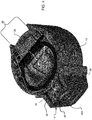
- the housing 40 includes a front portion 39, a middle portion 29, and a back portion 19.
- the middle portion 29 fastens to the front portion 39 via screws 31.
- the back portion 19 attaches to the middle portion 29 via a snap fit, in one example.
- These portions are typically made from plastic or other lightweight material that can be formed/molded to meet design and assembly considerations.
- Batteries 36 are located within the back portion 19 and the middle portion 29 of the housing 40.
- the batteries 36 provide a source of input power to the sensor module 60, the anti-tampering system, and the motion sensor system 21.
- the batteries 36 are attached to a rear side of the middle portion 29 of the housing 40, via a pull tab 37.
- the back portion 19 is a removable cover for the batteries 36.
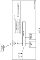
- Fig. 6 is a block diagram that illustrates various components of the sensor module 60.
- step 706 the controller 50 obtains another voltage from the magnetic field sensor 54 of the magnetometer 30.
- the controller 50 compares the obtained voltage to the reference voltage 129.
- the controller 50 polls the magnetic field sensor 54 on the order of 100 milliseconds to obtain its voltage.
- the polling interval is as large as 1 to 5 seconds to conserve the batteries 36.
- step 712 the controller 50 determines if the obtained voltage is less than the minimum voltage 109. If the voltage is less than the minimum voltage 109, the method transitions to step 714. Otherwise, the method transitions to the beginning of step 706 to obtain a new voltage from the magnetic field sensor 54.
Landscapes
- Physics & Mathematics (AREA)
- General Physics & Mathematics (AREA)
- Engineering & Computer Science (AREA)
- Multimedia (AREA)
- Signal Processing (AREA)
- Electromagnetism (AREA)
- Computer Security & Cryptography (AREA)
- Computer Networks & Wireless Communication (AREA)
- Business, Economics & Management (AREA)
- Emergency Management (AREA)
- Alarm Systems (AREA)
- Burglar Alarm Systems (AREA)
Claims (15)
- Ensemble (10) de dispositif de sécurité, comportant :un support (14) de montage ;un dispositif (12) de sécurité qui repose et peut tourner à l'intérieur du support (14) de montage autour d'un axe d'orientation ;un aimant permanent (28) fixé au support de montage ;un magnétomètre (30) contenu à l'intérieur du dispositif (12) de sécurité pour détecter un champ magnétique généré par l'aimant permanent ; etun moyen (50) de commande qui détermine des variations du champ magnétique détecté par le magnétomètre (30) qui sont indicatives d'une rotation du dispositif (12) de sécurité à l'intérieur du support (14) de montage, le moyen (50) de commande déterminant, en réponse au fait que les variations déterminées du champ magnétique se trouvent au-delà d'une plage autorisée, que la rotation du dispositif (12) de sécurité à l'intérieur du support (14) de montage est associée à une altération du dispositif (12) de sécurité.
- Ensemble (10) de dispositif de sécurité selon la revendication 1, le support (14) de montage comprenant un corps (68) et une partie supérieure s'étendant à partir du corps (68), et l'axe d'orientation (39) passant par le centre de la partie supérieure (38) du support (14) de montage et le long du corps (68) du support (14) de montage.
- Ensemble (10) de dispositif de sécurité selon la revendication 2, le dispositif (12) de sécurité comprenant un boîtier (40) qui peut être lié de façon amovible au support (14) de montage, et l'axe d'orientation (39) passant par le centre du boîtier (40) du dispositif (12) de sécurité lorsque le dispositif (12) de sécurité repose entièrement à l'intérieur du support (14) de montage.
- Ensemble (10) de dispositif de sécurité selon l'une quelconque des revendications précédentes, le support (14) de montage comprenant :
un corps (68) qui se monte sur une surface et un extracteur (58) compris à l'intérieur du corps, l'extracteur (58) étant fixé de façon amovible au corps (68) et se montant sur une même surface que le corps (68), et l'aimant permanent (28) étant fixé à l'extracteur (58). - Ensemble (10) de dispositif de sécurité selon l'une quelconque des revendications précédentes, le dispositif (12) de sécurité étant un détecteur (12) de mouvement ou une caméra de surveillance.
- Ensemble (10) de dispositif de sécurité selon l'une quelconque des revendications précédentes, le dispositif (12) de sécurité comportant un dispositif de détection d'incendie.
- Ensemble (10) de dispositif de sécurité selon l'une quelconque des revendications précédentes, le magnétomètre (30) comprenant un capteur à effet Hall et un noyau ferromagnétique (18).
- Ensemble (10) de dispositif de sécurité selon l'une quelconque des revendications précédentes, le magnétomètre (30) produisant des tensions dans le temps qui représentent le champ magnétique détecté de l'aimant permanent (28), et le moyen (50) de commande obtenant les tensions à partir du magnétomètre (30), et déterminant les variations du champ magnétique indicatives de la rotation du dispositif (12) de sécurité d'après les tensions obtenues à partir du magnétomètre (30).
- Ensemble (10) de dispositif de sécurité selon la revendication 8, le moyen (50) de commande stockant des tensions qui représentent le champ magnétique détecté, et le moyen (50) de commande déterminant que les variations du champ magnétique indicatives de la rotation du dispositif (12) de sécurité sont associées à l'altération du dispositif (12) de sécurité lorsque des tensions actuelles obtenues par le magnétomètre (30) indiquent les variations.
- Ensemble (10) de dispositif de sécurité selon l'une quelconque des revendications précédentes, le dispositif (12) de sécurité comprenant un boîtier (40) qui est généralement cylindrique.
- Procédé de détection d'une altération d'un dispositif (12) de sécurité, comportant les étapes consistant à :faire détecter, par un magnétomètre (30) contenu à l'intérieur du dispositif (12) de sécurité qui repose et peut tourner à l'intérieur d'un support (14) de montage autour d'un axe d'orientation, un champ magnétique généré par un aimant permanent (28) fixé au support (14) de montage ;déterminer des variations du champ magnétique détecté par le magnétomètre (30) qui sont indicatives d'une rotation du dispositif (12) de sécurité à l'intérieur du support (14) de montage ; etdéterminer, en réponse au fait que les variations déterminées du champ magnétique se trouvent au-delà d'une plage autorisée, que la rotation du dispositif (12) de sécurité à l'intérieur du support (14) de montage est associée à l'altération du dispositif (12) de sécurité.
- Procédé selon la revendication 11, le dispositif (12) de sécurité comprenant un boîtier (40) qui peut être lié de façon amovible au support (14) de montage, et l'axe d'orientation (39) passant par le centre du boîtier (40) du dispositif (12) de sécurité lorsque le dispositif (12) de sécurité repose entièrement à l'intérieur du support (14) de montage.
- Procédé selon la revendication 11, la détermination des variations du champ magnétique qui sont indicatives de la rotation du dispositif (12) de sécurité à l'intérieur du support (14) de montage comportant :la production, par le magnétomètre (30) contenu à l'intérieur du dispositif (12) de sécurité, de tensions dans le temps qui représentent le champ magnétique ;l'obtention de tensions actuelles à partir du magnétomètre (30) ; etla détermination des variations du champ magnétique d'après les tensions actuelles obtenues à partir du magnétomètre (30).
- Procédé selon la revendication 13, la détermination des variations du champ magnétique d'après les tensions actuelles obtenues à partir du magnétomètre (30) comportant :le stockage de tensions de référence qui représentent le champ magnétique au niveau du dispositif (12) de sécurité pour une position initiale du dispositif (12) de sécurité ; etla comparaison des tensions actuelles obtenues à partir du magnétomètre (30) aux tensions de référence pour déterminer si les tensions actuelles ont changé en comparaison des tensions de référence.
- Procédé selon la revendication 14, la détermination du fait que les tensions actuelles indiquent l'altération du dispositif (12) de sécurité ayant en outre lieu en réponse à :
la détermination du fait que les tensions actuelles sont supérieures à une tension maximum qui représente une valeur maximum du champ magnétique, ou que les tensions actuelles sont inférieures à une tension minimum qui représente une valeur minimum du champ magnétique.
Applications Claiming Priority (1)
| Application Number | Priority Date | Filing Date | Title |
|---|---|---|---|
| US15/953,624 US10565842B2 (en) | 2018-04-16 | 2018-04-16 | Method and device for omnidirectional and anti-sabotage anti-tampering detection |
Publications (2)
| Publication Number | Publication Date |
|---|---|
| EP3557552A1 EP3557552A1 (fr) | 2019-10-23 |
| EP3557552B1 true EP3557552B1 (fr) | 2021-06-09 |
Family
ID=66105259
Family Applications (1)
| Application Number | Title | Priority Date | Filing Date |
|---|---|---|---|
| EP19168760.7A Active EP3557552B1 (fr) | 2018-04-16 | 2019-04-11 | Procédé et dispositif de détection inviolable omnidirectionnelle et anti-sabotage |
Country Status (2)
| Country | Link |
|---|---|
| US (1) | US10565842B2 (fr) |
| EP (1) | EP3557552B1 (fr) |
Cited By (1)
| Publication number | Priority date | Publication date | Assignee | Title |
|---|---|---|---|---|
| EP4144193A1 (fr) * | 2020-04-29 | 2023-03-08 | Essence Security International Ltd. | Dispositif de sécurité |
Families Citing this family (8)
| Publication number | Priority date | Publication date | Assignee | Title |
|---|---|---|---|---|
| US10755554B2 (en) * | 2018-09-28 | 2020-08-25 | Nortek Security & Control Llc | Vector magnetic tamper detection for sensors |
| WO2020099521A1 (fr) * | 2018-11-13 | 2020-05-22 | Tyco Fire & Security Gmbh | Capteur de contact avec fonctionnalité de détection de masquage |
| US12078694B2 (en) | 2019-07-30 | 2024-09-03 | Google Llc | Sensor-based tamper detection for mounted electronic devices |
| EP3819887A1 (fr) * | 2019-11-07 | 2021-05-12 | Heim, Mark | Avertisseur de danger et procédé de fonctionnement d'un avertisseur de danger |
| ES2976588T3 (es) * | 2020-01-10 | 2024-08-05 | Verisure Sarl | Un conjunto de alarma |
| DE102020201959B4 (de) * | 2020-02-17 | 2021-10-28 | Continental Automotive Gmbh | Magnetfeldsensor mit einem Gerätegehäuse |
| US11852957B2 (en) | 2020-09-22 | 2023-12-26 | Google Llc | Thermal-control system for a security camera and associated security camera |
| US20250109971A1 (en) * | 2023-10-02 | 2025-04-03 | Carrier Corporation | Tamper-proof sensor assembly |
Family Cites Families (12)
| Publication number | Priority date | Publication date | Assignee | Title |
|---|---|---|---|---|
| EP1227452A1 (fr) | 2001-01-19 | 2002-07-31 | Siemens Building Technologies AG | Système de sécurité et avertisseur de danger pour surveiller des paramètres de risque |
| WO2003019492A1 (fr) * | 2001-08-23 | 2003-03-06 | Johnny Pollard | Systeme de detection d'incendie |
| US7388484B2 (en) * | 2005-08-16 | 2008-06-17 | Honeywell International Inc. | Conductive tamper switch for security devices |
| US7528717B2 (en) * | 2006-06-14 | 2009-05-05 | Honeywell International Inc. | Tamper detection mechanism for blind installation of circular sensors |
| US7728720B2 (en) * | 2006-07-28 | 2010-06-01 | Deere & Company | System and method for monitoring a status of a member of a vehicle |
| US7667600B2 (en) | 2006-12-16 | 2010-02-23 | Roc2Loc, Inc. | Methods and apparatus for security device removal detection |
| EP2269177A4 (fr) * | 2008-03-24 | 2014-01-22 | Strata Proximity Systems Llc | Ajustement de champ électromagnétique pour une détection de proximité |
| GB2487560B (en) | 2011-01-26 | 2013-09-04 | Thorn Security | Fire detector unit |
| WO2014047078A1 (fr) * | 2012-09-18 | 2014-03-27 | Vootner Goushe Llc | Système de détection pour la protection d'œuvres artistiques et d'autres objets de valeur |
| US20170228603A1 (en) * | 2013-03-15 | 2017-08-10 | August Home, Inc. | Door lock system with wide view camera |
| US10051347B2 (en) * | 2013-08-02 | 2018-08-14 | Stephen Hollis | Displacement sensor |
| US9739637B2 (en) * | 2014-10-31 | 2017-08-22 | Allegro Microsystems, Llc | Magnetic field motion sensor and related techniques |
-
2018
- 2018-04-16 US US15/953,624 patent/US10565842B2/en active Active
-
2019
- 2019-04-11 EP EP19168760.7A patent/EP3557552B1/fr active Active
Non-Patent Citations (1)
| Title |
|---|
| None * |
Cited By (1)
| Publication number | Priority date | Publication date | Assignee | Title |
|---|---|---|---|---|
| EP4144193A1 (fr) * | 2020-04-29 | 2023-03-08 | Essence Security International Ltd. | Dispositif de sécurité |
Also Published As
| Publication number | Publication date |
|---|---|
| US20190318595A1 (en) | 2019-10-17 |
| US10565842B2 (en) | 2020-02-18 |
| EP3557552A1 (fr) | 2019-10-23 |
Similar Documents
| Publication | Publication Date | Title |
|---|---|---|
| EP3557552B1 (fr) | Procédé et dispositif de détection inviolable omnidirectionnelle et anti-sabotage | |
| EP3082115B1 (fr) | Rétroaction d'installation guidée pour un capteur d'ouverture | |
| EP3665663B1 (fr) | Capteur de sécurité proche-éloigné | |
| US12474420B2 (en) | Sensor-based tamper detection for mounted electronic devices | |
| US7187280B2 (en) | Alarm system with thin profile | |
| US9947189B2 (en) | Home automation device for monitoring the movement of a swinging wing and method for enhancing the reliability of such a device | |
| US20160323118A1 (en) | Self-Identifying, Multi-Function Sensor Device and Monitoring System Including Same | |
| EP3625780B1 (fr) | Système et procédé pour désarmer automatiquement un système de détection d'intrusion | |
| EP3249623B1 (fr) | Capteur et procédé de détection d'intrusion | |
| EP3142089B1 (fr) | Notification sur l' armement d' un système basée sur une position ble | |
| CN207409080U (zh) | 一种门磁装置 | |
| JPH1061273A (ja) | 引戸用見張番システム | |
| US20080031607A1 (en) | Burglar alarm monitoring apparatus | |
| EP4252209B1 (fr) | Composant de système de surveillance | |
| US20190311591A1 (en) | Fire extinguisher monitoring system and method | |
| KR200301032Y1 (ko) | 태양전지가 구비된 방범경보장치용 감지센서단말 | |
| US12597324B2 (en) | Intrusion detection system, apparatus and method | |
| US12424076B2 (en) | Enhanced visual and audio device for use in access control systems | |
| EP4550287A1 (fr) | Périphérique de sécurité | |
| CN107369280A (zh) | 一种门磁装置 | |
| US9741219B1 (en) | Tamper-proof building alarm system | |
| CA2919039A1 (fr) | Modele d'interrupteur de fonction de verrouillage intelligent destine aux detecteurs d'intrusion | |
| US20180225942A1 (en) | Audible sensor chip | |
| KR20030008870A (ko) | 홈 방범시스템 및 제어방법 | |
| GB2572328A (en) | Security system |
Legal Events
| Date | Code | Title | Description |
|---|---|---|---|
| PUAI | Public reference made under article 153(3) epc to a published international application that has entered the european phase |
Free format text: ORIGINAL CODE: 0009012 |
|
| STAA | Information on the status of an ep patent application or granted ep patent |
Free format text: STATUS: REQUEST FOR EXAMINATION WAS MADE |
|
| 17P | Request for examination filed |
Effective date: 20190411 |
|
| AK | Designated contracting states |
Kind code of ref document: A1 Designated state(s): AL AT BE BG CH CY CZ DE DK EE ES FI FR GB GR HR HU IE IS IT LI LT LU LV MC MK MT NL NO PL PT RO RS SE SI SK SM TR |
|
| AX | Request for extension of the european patent |
Extension state: BA ME |
|
| GRAP | Despatch of communication of intention to grant a patent |
Free format text: ORIGINAL CODE: EPIDOSNIGR1 |
|
| STAA | Information on the status of an ep patent application or granted ep patent |
Free format text: STATUS: GRANT OF PATENT IS INTENDED |
|
| INTG | Intention to grant announced |
Effective date: 20201104 |
|
| GRAS | Grant fee paid |
Free format text: ORIGINAL CODE: EPIDOSNIGR3 |
|
| GRAA | (expected) grant |
Free format text: ORIGINAL CODE: 0009210 |
|
| STAA | Information on the status of an ep patent application or granted ep patent |
Free format text: STATUS: THE PATENT HAS BEEN GRANTED |
|
| AK | Designated contracting states |
Kind code of ref document: B1 Designated state(s): AL AT BE BG CH CY CZ DE DK EE ES FI FR GB GR HR HU IE IS IT LI LT LU LV MC MK MT NL NO PL PT RO RS SE SI SK SM TR |
|
| REG | Reference to a national code |
Ref country code: GB Ref legal event code: FG4D |
|
| REG | Reference to a national code |
Ref country code: CH Ref legal event code: EP Ref country code: AT Ref legal event code: REF Ref document number: 1401142 Country of ref document: AT Kind code of ref document: T Effective date: 20210615 |
|
| REG | Reference to a national code |
Ref country code: DE Ref legal event code: R096 Ref document number: 602019005169 Country of ref document: DE |
|
| REG | Reference to a national code |
Ref country code: IE Ref legal event code: FG4D |
|
| REG | Reference to a national code |
Ref country code: LT Ref legal event code: MG9D |
|
| PG25 | Lapsed in a contracting state [announced via postgrant information from national office to epo] |
Ref country code: FI Free format text: LAPSE BECAUSE OF FAILURE TO SUBMIT A TRANSLATION OF THE DESCRIPTION OR TO PAY THE FEE WITHIN THE PRESCRIBED TIME-LIMIT Effective date: 20210609 Ref country code: HR Free format text: LAPSE BECAUSE OF FAILURE TO SUBMIT A TRANSLATION OF THE DESCRIPTION OR TO PAY THE FEE WITHIN THE PRESCRIBED TIME-LIMIT Effective date: 20210609 Ref country code: LT Free format text: LAPSE BECAUSE OF FAILURE TO SUBMIT A TRANSLATION OF THE DESCRIPTION OR TO PAY THE FEE WITHIN THE PRESCRIBED TIME-LIMIT Effective date: 20210609 Ref country code: BG Free format text: LAPSE BECAUSE OF FAILURE TO SUBMIT A TRANSLATION OF THE DESCRIPTION OR TO PAY THE FEE WITHIN THE PRESCRIBED TIME-LIMIT Effective date: 20210909 |
|
| REG | Reference to a national code |
Ref country code: AT Ref legal event code: MK05 Ref document number: 1401142 Country of ref document: AT Kind code of ref document: T Effective date: 20210609 |
|
| REG | Reference to a national code |
Ref country code: NL Ref legal event code: MP Effective date: 20210609 |
|
| PG25 | Lapsed in a contracting state [announced via postgrant information from national office to epo] |
Ref country code: GR Free format text: LAPSE BECAUSE OF FAILURE TO SUBMIT A TRANSLATION OF THE DESCRIPTION OR TO PAY THE FEE WITHIN THE PRESCRIBED TIME-LIMIT Effective date: 20210910 Ref country code: LV Free format text: LAPSE BECAUSE OF FAILURE TO SUBMIT A TRANSLATION OF THE DESCRIPTION OR TO PAY THE FEE WITHIN THE PRESCRIBED TIME-LIMIT Effective date: 20210609 Ref country code: NO Free format text: LAPSE BECAUSE OF FAILURE TO SUBMIT A TRANSLATION OF THE DESCRIPTION OR TO PAY THE FEE WITHIN THE PRESCRIBED TIME-LIMIT Effective date: 20210909 Ref country code: SE Free format text: LAPSE BECAUSE OF FAILURE TO SUBMIT A TRANSLATION OF THE DESCRIPTION OR TO PAY THE FEE WITHIN THE PRESCRIBED TIME-LIMIT Effective date: 20210609 Ref country code: RS Free format text: LAPSE BECAUSE OF FAILURE TO SUBMIT A TRANSLATION OF THE DESCRIPTION OR TO PAY THE FEE WITHIN THE PRESCRIBED TIME-LIMIT Effective date: 20210609 |
|
| PG25 | Lapsed in a contracting state [announced via postgrant information from national office to epo] |
Ref country code: SM Free format text: LAPSE BECAUSE OF FAILURE TO SUBMIT A TRANSLATION OF THE DESCRIPTION OR TO PAY THE FEE WITHIN THE PRESCRIBED TIME-LIMIT Effective date: 20210609 Ref country code: NL Free format text: LAPSE BECAUSE OF FAILURE TO SUBMIT A TRANSLATION OF THE DESCRIPTION OR TO PAY THE FEE WITHIN THE PRESCRIBED TIME-LIMIT Effective date: 20210609 Ref country code: RO Free format text: LAPSE BECAUSE OF FAILURE TO SUBMIT A TRANSLATION OF THE DESCRIPTION OR TO PAY THE FEE WITHIN THE PRESCRIBED TIME-LIMIT Effective date: 20210609 Ref country code: PT Free format text: LAPSE BECAUSE OF FAILURE TO SUBMIT A TRANSLATION OF THE DESCRIPTION OR TO PAY THE FEE WITHIN THE PRESCRIBED TIME-LIMIT Effective date: 20211011 Ref country code: AT Free format text: LAPSE BECAUSE OF FAILURE TO SUBMIT A TRANSLATION OF THE DESCRIPTION OR TO PAY THE FEE WITHIN THE PRESCRIBED TIME-LIMIT Effective date: 20210609 Ref country code: CZ Free format text: LAPSE BECAUSE OF FAILURE TO SUBMIT A TRANSLATION OF THE DESCRIPTION OR TO PAY THE FEE WITHIN THE PRESCRIBED TIME-LIMIT Effective date: 20210609 Ref country code: SK Free format text: LAPSE BECAUSE OF FAILURE TO SUBMIT A TRANSLATION OF THE DESCRIPTION OR TO PAY THE FEE WITHIN THE PRESCRIBED TIME-LIMIT Effective date: 20210609 Ref country code: EE Free format text: LAPSE BECAUSE OF FAILURE TO SUBMIT A TRANSLATION OF THE DESCRIPTION OR TO PAY THE FEE WITHIN THE PRESCRIBED TIME-LIMIT Effective date: 20210609 Ref country code: ES Free format text: LAPSE BECAUSE OF FAILURE TO SUBMIT A TRANSLATION OF THE DESCRIPTION OR TO PAY THE FEE WITHIN THE PRESCRIBED TIME-LIMIT Effective date: 20210609 |
|
| PG25 | Lapsed in a contracting state [announced via postgrant information from national office to epo] |
Ref country code: PL Free format text: LAPSE BECAUSE OF FAILURE TO SUBMIT A TRANSLATION OF THE DESCRIPTION OR TO PAY THE FEE WITHIN THE PRESCRIBED TIME-LIMIT Effective date: 20210609 |
|
| REG | Reference to a national code |
Ref country code: DE Ref legal event code: R097 Ref document number: 602019005169 Country of ref document: DE |
|
| PLBE | No opposition filed within time limit |
Free format text: ORIGINAL CODE: 0009261 |
|
| STAA | Information on the status of an ep patent application or granted ep patent |
Free format text: STATUS: NO OPPOSITION FILED WITHIN TIME LIMIT |
|
| PG25 | Lapsed in a contracting state [announced via postgrant information from national office to epo] |
Ref country code: DK Free format text: LAPSE BECAUSE OF FAILURE TO SUBMIT A TRANSLATION OF THE DESCRIPTION OR TO PAY THE FEE WITHIN THE PRESCRIBED TIME-LIMIT Effective date: 20210609 |
|
| 26N | No opposition filed |
Effective date: 20220310 |
|
| PG25 | Lapsed in a contracting state [announced via postgrant information from national office to epo] |
Ref country code: AL Free format text: LAPSE BECAUSE OF FAILURE TO SUBMIT A TRANSLATION OF THE DESCRIPTION OR TO PAY THE FEE WITHIN THE PRESCRIBED TIME-LIMIT Effective date: 20210609 |
|
| PG25 | Lapsed in a contracting state [announced via postgrant information from national office to epo] |
Ref country code: IT Free format text: LAPSE BECAUSE OF FAILURE TO SUBMIT A TRANSLATION OF THE DESCRIPTION OR TO PAY THE FEE WITHIN THE PRESCRIBED TIME-LIMIT Effective date: 20210609 |
|
| REG | Reference to a national code |
Ref country code: CH Ref legal event code: PL |
|
| REG | Reference to a national code |
Ref country code: BE Ref legal event code: MM Effective date: 20220430 |
|
| PG25 | Lapsed in a contracting state [announced via postgrant information from national office to epo] |
Ref country code: MC Free format text: LAPSE BECAUSE OF FAILURE TO SUBMIT A TRANSLATION OF THE DESCRIPTION OR TO PAY THE FEE WITHIN THE PRESCRIBED TIME-LIMIT Effective date: 20210609 Ref country code: LU Free format text: LAPSE BECAUSE OF NON-PAYMENT OF DUE FEES Effective date: 20220411 Ref country code: LI Free format text: LAPSE BECAUSE OF NON-PAYMENT OF DUE FEES Effective date: 20220430 Ref country code: CH Free format text: LAPSE BECAUSE OF NON-PAYMENT OF DUE FEES Effective date: 20220430 |
|
| PG25 | Lapsed in a contracting state [announced via postgrant information from national office to epo] |
Ref country code: BE Free format text: LAPSE BECAUSE OF NON-PAYMENT OF DUE FEES Effective date: 20220430 |
|
| PG25 | Lapsed in a contracting state [announced via postgrant information from national office to epo] |
Ref country code: IE Free format text: LAPSE BECAUSE OF NON-PAYMENT OF DUE FEES Effective date: 20220411 |
|
| PG25 | Lapsed in a contracting state [announced via postgrant information from national office to epo] |
Ref country code: HU Free format text: LAPSE BECAUSE OF FAILURE TO SUBMIT A TRANSLATION OF THE DESCRIPTION OR TO PAY THE FEE WITHIN THE PRESCRIBED TIME-LIMIT; INVALID AB INITIO Effective date: 20190411 |
|
| PG25 | Lapsed in a contracting state [announced via postgrant information from national office to epo] |
Ref country code: MK Free format text: LAPSE BECAUSE OF FAILURE TO SUBMIT A TRANSLATION OF THE DESCRIPTION OR TO PAY THE FEE WITHIN THE PRESCRIBED TIME-LIMIT Effective date: 20210609 Ref country code: CY Free format text: LAPSE BECAUSE OF FAILURE TO SUBMIT A TRANSLATION OF THE DESCRIPTION OR TO PAY THE FEE WITHIN THE PRESCRIBED TIME-LIMIT Effective date: 20210609 |
|
| PG25 | Lapsed in a contracting state [announced via postgrant information from national office to epo] |
Ref country code: MT Free format text: LAPSE BECAUSE OF FAILURE TO SUBMIT A TRANSLATION OF THE DESCRIPTION OR TO PAY THE FEE WITHIN THE PRESCRIBED TIME-LIMIT Effective date: 20210609 |
|
| PGFP | Annual fee paid to national office [announced via postgrant information from national office to epo] |
Ref country code: DE Payment date: 20250428 Year of fee payment: 7 |
|
| PGFP | Annual fee paid to national office [announced via postgrant information from national office to epo] |
Ref country code: FR Payment date: 20250424 Year of fee payment: 7 |
|
| PG25 | Lapsed in a contracting state [announced via postgrant information from national office to epo] |
Ref country code: TR Free format text: LAPSE BECAUSE OF FAILURE TO SUBMIT A TRANSLATION OF THE DESCRIPTION OR TO PAY THE FEE WITHIN THE PRESCRIBED TIME-LIMIT Effective date: 20210609 |
|
| PGFP | Annual fee paid to national office [announced via postgrant information from national office to epo] |
Ref country code: GB Payment date: 20260304 Year of fee payment: 8 |