EP3558077B1 - Module d'ébouillantage et machine de préparation de boissons - Google Patents
Module d'ébouillantage et machine de préparation de boissons Download PDFInfo
- Publication number
- EP3558077B1 EP3558077B1 EP17826503.9A EP17826503A EP3558077B1 EP 3558077 B1 EP3558077 B1 EP 3558077B1 EP 17826503 A EP17826503 A EP 17826503A EP 3558077 B1 EP3558077 B1 EP 3558077B1
- Authority
- EP
- European Patent Office
- Prior art keywords
- brewing module
- brewing
- capsule
- blowing device
- air
- Prior art date
- Legal status (The legal status is an assumption and is not a legal conclusion. Google has not performed a legal analysis and makes no representation as to the accuracy of the status listed.)
- Active
Links
Images



Classifications
-
- A—HUMAN NECESSITIES
- A47—FURNITURE; DOMESTIC ARTICLES OR APPLIANCES; COFFEE MILLS; SPICE MILLS; SUCTION CLEANERS IN GENERAL
- A47J—KITCHEN EQUIPMENT; COFFEE MILLS; SPICE MILLS; APPARATUS FOR MAKING BEVERAGES
- A47J31/00—Apparatus for making beverages
- A47J31/24—Coffee-making apparatus in which hot water is passed through the filter under pressure, i.e. in which the coffee grounds are extracted under pressure
- A47J31/34—Coffee-making apparatus in which hot water is passed through the filter under pressure, i.e. in which the coffee grounds are extracted under pressure with hot water under liquid pressure
- A47J31/36—Coffee-making apparatus in which hot water is passed through the filter under pressure, i.e. in which the coffee grounds are extracted under pressure with hot water under liquid pressure with mechanical pressure-producing means
- A47J31/3604—Coffee-making apparatus in which hot water is passed through the filter under pressure, i.e. in which the coffee grounds are extracted under pressure with hot water under liquid pressure with mechanical pressure-producing means with a mechanism arranged to move the brewing chamber between loading, infusing and ejecting stations
- A47J31/3623—Cartridges being employed
- A47J31/3633—Means to perform transfer from a loading position to an infusing position
-
- A—HUMAN NECESSITIES
- A47—FURNITURE; DOMESTIC ARTICLES OR APPLIANCES; COFFEE MILLS; SPICE MILLS; SUCTION CLEANERS IN GENERAL
- A47J—KITCHEN EQUIPMENT; COFFEE MILLS; SPICE MILLS; APPARATUS FOR MAKING BEVERAGES
- A47J31/00—Apparatus for making beverages
- A47J31/24—Coffee-making apparatus in which hot water is passed through the filter under pressure, i.e. in which the coffee grounds are extracted under pressure
- A47J31/34—Coffee-making apparatus in which hot water is passed through the filter under pressure, i.e. in which the coffee grounds are extracted under pressure with hot water under liquid pressure
- A47J31/36—Coffee-making apparatus in which hot water is passed through the filter under pressure, i.e. in which the coffee grounds are extracted under pressure with hot water under liquid pressure with mechanical pressure-producing means
- A47J31/3604—Coffee-making apparatus in which hot water is passed through the filter under pressure, i.e. in which the coffee grounds are extracted under pressure with hot water under liquid pressure with mechanical pressure-producing means with a mechanism arranged to move the brewing chamber between loading, infusing and ejecting stations
- A47J31/3623—Cartridges being employed
-
- A—HUMAN NECESSITIES
- A47—FURNITURE; DOMESTIC ARTICLES OR APPLIANCES; COFFEE MILLS; SPICE MILLS; SUCTION CLEANERS IN GENERAL
- A47J—KITCHEN EQUIPMENT; COFFEE MILLS; SPICE MILLS; APPARATUS FOR MAKING BEVERAGES
- A47J31/00—Apparatus for making beverages
- A47J31/44—Parts or details or accessories of beverage-making apparatus
- A47J31/4492—Means to read code provided on ingredient pod or cartridge
-
- A—HUMAN NECESSITIES
- A47—FURNITURE; DOMESTIC ARTICLES OR APPLIANCES; COFFEE MILLS; SPICE MILLS; SUCTION CLEANERS IN GENERAL
- A47J—KITCHEN EQUIPMENT; COFFEE MILLS; SPICE MILLS; APPARATUS FOR MAKING BEVERAGES
- A47J31/00—Apparatus for making beverages
- A47J31/44—Parts or details or accessories of beverage-making apparatus
- A47J31/46—Dispensing spouts, pumps, drain valves or like liquid transporting devices
- A47J31/468—Pumping means
-
- A—HUMAN NECESSITIES
- A47—FURNITURE; DOMESTIC ARTICLES OR APPLIANCES; COFFEE MILLS; SPICE MILLS; SUCTION CLEANERS IN GENERAL
- A47J—KITCHEN EQUIPMENT; COFFEE MILLS; SPICE MILLS; APPARATUS FOR MAKING BEVERAGES
- A47J31/00—Apparatus for making beverages
- A47J31/44—Parts or details or accessories of beverage-making apparatus
- A47J31/60—Cleaning devices
Definitions
- the invention relates to extraction devices for preparing beverages or the like from an extraction material contained in a portion capsule, for example ground coffee.
- a brewing module for an extraction device a capsule recognition module and a beverage preparation machine with such a brewing module and / or capsule recognition module.
- Extraction devices for preparing beverages or the like from an extraction material present in portion packaging are known, for example, as coffee or espresso machines.
- the portion packs are designed as capsules in which the extraction material is, for example, sealed airtight.
- the capsule is pierced, for example on two opposite sides.
- An extraction liquid - generally hot water - is then introduced on the first side.
- the extraction product is discharged from the capsule. This takes place in a so-called brewing module.
- One such has a brewing chamber in which the capsule is received.
- Brewing modules are particularly popular in which the capsule is thrown in and the brewing chamber is closed manually by means of an operating lever or automatically motorized, whereby when the brewing chamber is opened again after the brewing process, the capsule is automatically removed from the brewing chamber and ejected into a capsule container.
- Such brewing modules with automatic capsule ejection are generally horizontal Formed brewing modules, ie the capsule is inserted from above, the closure of the brewing chamber is a horizontal relative movement of two brewing module parts, the brewing liquid flows essentially horizontally, and the capsule container is formed below the brewing chamber.
- One problem area in this context relates to the detection of capsule properties, for example the reading out of information provided on the capsule in order to trigger a brewing process as a function of this information.
- One possibility for this is to provide the capsule with a suitable marking or color combination and to detect it optically. This is done, for example, with a camera. Because the brewing chamber itself is too hot and susceptible to contamination during operation, the information is generally recorded before the brewing process, while the capsule is still outside the brewing chamber, at a capsule detection position. However, practical problems then also arise with such a process carried out in the immediate vicinity of the brewing chamber.
- the object of the invention is to provide a beverage preparation machine and a brewing module for such a machine which overcome the disadvantages of the prior art and which have the simplest possible construction and still allow reliable optical capsule recognition in the vicinity of the brewing chamber.
- the construction should preferably also be suitable for implementation as a manually operated brewing module.
- Such a window element can be a conventional window pane made of a transparent material (for example glass or a transparent plastic) with plane-parallel surfaces, or it can optionally have a lens function.
- the window element can also act as a camera lens of the camera.
- the brewing module is characterized by a mechanically drivable blowing device for generating an air flow, which is arranged to generate an air flow on the side of the window element towards the capsule recognition position.
- the blowing device is mounted in such a way that it is driven by a relative movement of elements of the brewing module, which relative movement is generated by the drive or the transmission mechanism.
- This relative movement of the elements of the brewing module can in particular be a movement that takes place anyway during normal operation, for example the actuation of an actuating element to close the brewing module and / or the closing of the brewing chamber.
- the mentioned elements of the brewing module, which are subject to the relative movement, can in particular be such an actuating element, the second brewing module part, elements of the transmission mechanism and / or parts fixed to the housing.
- the window element is that transparent part of the capsule recognition device that separates the light-sensitive element of the optical sensor from the area where the capsule is located and through which the Capsule detection takes place. If several such transparent elements are present one behind the other, it is the outermost such transparent element, viewed from the camera, which is closest to the capsule recognition position.
- This transparent part is generally a window with or without a lens function (in this context a camera lens is also referred to as a "window" if it simultaneously separates the area of the light-sensitive element from the area of the capsule).
- the air flow is guided over the window on the capsule side in order to counteract fogging of the window and also to clean it.
- the blowing device is driven between two coupling points in that these coupling points are moved relative to one another, specifically in such a way that their distance is reduced or increased. This allows the blower to act in the manner of a bellows.
- the blowing device has a first blowing device element and a second blowing device element, between which an active volume is formed, which can be enlarged or reduced by a relative movement of the first and second blowing device elements.
- the active volume is connected to at least one air connection through which air is sucked into the active volume or air is blown out of the active volume when the first and second blowing device elements are moved relative to one another.
- the blower device can have a cylinder (as a first blower device element) and a piston which is displaceable therein (as a second blower device element), which by movement in the cylinder active volume increases or decreases and thus either sucks air into the cylinder or forces air out of the cylinder. Since the cylinder has two air connections with corresponding valves, a pumping effect can be achieved, with air being sucked in from a certain location when the active volume is increased and blown out to another location near the window element when the volume is reduced.
- the blower can be designed as a bellows in the narrower sense, in that the movement of the coupling points causes a movement of two plates as the blower elements relative to one another, between which a flexible, for example suitably folded membrane surrounds a volume, the size of which is the relative movement changes.
- a flexible, for example suitably folded membrane surrounds a volume, the size of which is the relative movement changes.
- blower devices which can be driven by translatory movements and / or pivoting movements or possibly rotary movements (for example a gear wheel of the transmission mechanism) are also conceivable.
- the drive is a purely mechanical drive.
- the brewing module can have an operating element which can be moved manually between a first and a second operating element position in order to directly or indirectly effect a movement of the second brewing module part relative to the first brewing module part via the transmission mechanism.
- Such a control element then belongs to the mechanical drive or forms it.
- Such an operating element can in particular be an operating lever which can be brought from the first to the second position by a tilting movement from top to bottom. In the second position, for example, the operating lever closes a capsule insertion opening which is formed by a housing of the beverage preparation machine - for example the brewing module.
- the blowing device is arranged between a first coupling point arranged on the operating element and a second coupling point, for example fixed to the housing. If necessary, the mentioned coupling points can be firmly connected to the first or second blowing device element.
- the brewing module can also have an energy store, which is set up to temporarily store energy coupled into the brewing module by moving the operating element from the first to the second position and triggered by a release in a movement from the first brewing module part position to the to implement the second brewing module part position again.
- Such an energy store can in particular be a spring, the operating element then being moved into the second position against the force of the spring and the spring being tensioned as a result. After the release, the spring is relaxed in that the second brewing module part is moved relative to the first brewing module part.
- a damping mechanism can be present which prevents the second brewing module part - or the operating element - from being accelerated too much during the corresponding movement caused by the spring and thus from snapping against a stop.
- a damping mechanism can be formed in the energy store itself or separately therefrom.
- the energy store is a gas pressure spring. This has the advantage that a damping mechanism can be integrated into the spring.
- the energy store exerts, for example, directly or indirectly a force on the second brewing module part in the direction of the second brewing module part position and on the operating element in the direction of the first position:
- the brewing chamber closes, when the energy store is full and the operating element is not blocked, the operating element moves back towards the first position.
- the latter can be used when a preparation process is to be interrupted, ie when the capsule insert opening is to be accessible again so that the capsule can be removed.
- the blowing device can for example be arranged parallel to the energy storage device, i.e. it can be mounted between the same two axes which move relative to one another during operation when charging and discharging the energy storage device.
- Embodiments with an energy store can have a first locking mechanism which is set up, depending on the state, to prevent or release a movement of the second brewing module part away from the first brewing module part position.
- such embodiments can have a second locking mechanism which is set up, depending on the state, to prevent or release a movement of the operating element away from the second operating element position.
- the drive is a motor drive.
- a linear movement of the brewing module parts relative to one another can also be brought about by such a device via the transmission mechanism.
- the blowing device is then preferably driven in that it is arranged between elements of the transmission mechanism, the second brewing module part and / or a point fixed to the housing.
- the blowing device can be arranged between a first coupling point connected to the second brewing module part and a second coupling point, for example fixed to the housing.
- the blowing device is arranged between (other) elements of a lever mechanism which forms the transmission mechanism.
- An arrangement which causes an air flow to the capsule recognition device immediately before the capsule recognition is particularly advantageous. This is particularly the case with arrangements in which the blowing device is actuated directly or via the transmission mechanism by moving the actuating element.
- the second brewing module part is movable relative to the first brewing module part, for example, in that the first brewing module part is mounted fixed to the housing and the second brewing module part is moved relative to the housing, in particular in a linear-translatory manner, in particular horizontally.
- a movement of both brewing module parts relative to the housing or a movement only of the first brewing module part relative to the housing is not excluded.
- the second brewing module part can be an injector, through which the portion capsule is pierced and from which, for example, hot water is introduced as brewing liquid into the portion capsule.
- the first brewing module part can form a discharge device for discharging the extraction product from the capsule.
- it has piercing elements on the extraction side, for example for piercing the capsule on the extraction side or other structures which open the capsule on the extraction side.
- the capsule recognition device is set up to carry out an optical capsule recognition, i.e. to read out optical features of the portion capsule via an optical sensor.
- a lighting means can also be present which illuminates the capsule in a controlled manner.
- the optical sensor is in particular a camera and for this purpose has a camera sensor with a sensor array (for example CCD or CMOS array).
- the program used by the coffee machine for brewing can also be selected on the basis of the recognized capsule type, for example the brewing pressure, the brewing duration and possibly also the temperature and / or other properties can be set depending on whether the inserted capsule is used for the preparation of e.g. ristretto, espresso or lungo is provided.
- Suitable optically readable features are, for example, a bar code, a 2D matrix code (e.g. QR code or Aztec code), a pictogram (icon) and / or a specific color scheme. Also a code according to WO 2016/091859 , WO 2016/091860 and or WO 2016/091861 it is an option.
- the capsule recognition device is assigned to the brewing module, since it belongs to that part of the beverage preparation machine that receives the capsule and interacts with it, which part is called brewing module in this text.
- a brewing module within the meaning of the present text can, but does not have to, be available as a separate, independent and exchangeable module. It can also be composed of various components integrated into the beverage preparation machine.
- the capsule recognition position at which the recognition of the optical features takes place is preferably different from the brewing position and can, for example, be above this.
- the capsule Before or during the movement of the second brewing module part relative to the first brewing module part to close the brewing chamber, in these embodiments the capsule is transported from the capsule recognition position into the brewing position, for example by falling down.
- a holding means which at least partially reaches under the capsule at the capsule recognition position, is withdrawn.
- the blowing device can be connected - for example via an air suction hose - to an area of the beverage preparation machine in which there is particularly dry and / or particularly warm air, in particular in the vicinity of the water heating means.
- an area can lie inside or outside the beverage preparation machine housing.
- the air intake hose leads to a location adjacent to the water heating means where Due to the resulting waste heat, the temperature is slightly higher and the air is therefore preheated.
- the invention also relates to a beverage preparation machine with a brewing module of the type discussed.
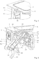
- the brewing module 1 has a brewing module housing 2. Two brewing module parts which can be moved relative to one another are guided in the brewing module housing 2, namely a diverting device 3 and an injector 4.
- the injector 4 has perforation elements for piercing a portion capsule 10 which is at least partially filled with an extraction material, for example ground coffee.
- the injector 4 is set up to introduce a liquid - for example hot water - through the perforation elements or past them into the pierced capsule, the water being able to be supplied via a water supply (not shown) which can for example have a flexible hose.
- the diverting device 3 also has perforation elements, namely extraction-side piercing tips 39.
- perforation elements namely extraction-side piercing tips 39.
- These can, for example, be designed as in FIG WO 2015/039258 or in WO 2010/118544 described or have a different configuration; It is also possible to use principles other than piercing tips, for example with grid-like structures.
- the diversion device has guide means 31 protruding towards the injector side on both sides of the capsule, as shown, for example, in FIG WO 2015/048914 are described, the content of which is expressly referred to here with regard to the functioning of these guide means.
- a capsule is placed between the discharge device 3 and the injector 4, and these are moved towards one another in such a way that a brewing chamber comprising the capsule is formed between them.
- the hot water is supplied to the capsule under pressure by the injector, and the extraction product flows off through the discharge device 3 via a beverage outlet 13 into a drinking vessel placed underneath, for example.
- the relative movement of the second brewing module part (injector) relative to the first brewing module part (diversion device) is achieved in the embodiment described here in that the diversion device 3 is mounted fixed to the housing, while the injector 4 can be moved along the horizontal axis.
- the brewing module As the brewing position located between the diverting device 3 and the injector 4 there is a capsule recognition position, into which the capsule passes after being inserted through a capsule insertion opening.
- the brewing module accordingly has a capsule recognition device 5 with a camera, the structure of which, for example, at least partially corresponds to that shown in FIG WO 2016/087190 corresponds to the structure described.
- the brewing module is designed in particular to hold the capsule inserted through the capsule insertion opening in the capsule recognition position before it moves down into the brewing position after successful capsule recognition and possibly after a further step (e.g. triggering of the brewing by the user).
- a mechanism can be present, for example, which comprises an element which engages under the capsule at the capsule recognition position and can be retracted in an electromechanically controlled manner for the transition to the brewing position.
- Other mechanisms for example purely mechanical, are also conceivable.
- the brewing module has an operating lever 6 which is mounted on a first fixed bearing point 20 and can be pivoted about it.
- the transmission mechanism from the operating lever 6 to the injector 4 is a lever mechanism and comprises a first toggle lever and a second toggle lever.
- the first toggle lever is formed by a first lever arm 21 engaging the operating lever and a second lever arm 22 which are pivotably connected to one another via a first toggle lever pin 23, so that a first knee joint is formed.
- the second toggle lever is formed by a third lever arm 24 and a fourth lever arm 25, which are pivotably connected to one another via a second toggle lever pin 26, so that a second knee joint is formed.
- the third lever arm 24 is mounted on a second fixed bearing point 28 and can be pivoted about it.
- the fourth lever arm 25 engages the injector 4 and is pivotable about a bearing pin 41 of the injector 4.
- the injector 4 is mounted in such a way that it can be positioned between the first brewing module part position (in Fig. 1 shown) and the second brewing module part position (in Fig. 3 visible) can be moved horizontally.
- the second lever arm 22 engages the second knee joint, for example by engaging with the second toggle lever pin 26.
- a gas pressure spring 7 engages on the first knee joint and extends between a third fixed bearing point 29, about which the gas pressure spring is pivotable, and the first knee joint, whereby it is in engagement with the first toggle lever bolt 23, for example.
- the brewing module also has two locking mechanisms.
- a first locking mechanism is configured to prevent a movement of the second brewing module part away from the first brewing module part position.
- the first locking mechanism has a locking bolt 81, for example magnetically triggered axially displaceable, which can be brought into engagement with the third and fourth lever arms in order to prevent the third and fourth lever arm from pivoting relative to one another in the blocked state, which - there the third lever arm with a fixed bearing point is connected - a movement of the injector 4 is also completely prevented.
- a second locking mechanism is set up to block the operating lever 6 relative to the housing 2.
- the second locking mechanism works according to the known so-called ballpoint pen principle.
- a locking sleeve 83 is provided for this purpose, which can be pressed down by the operating lever itself against a spring force and which is guided so that it is rotated by a predetermined angle - for example 90 ° - each time it is pressed down.
- the rotation can, for example, be effected in a manner known per se by a control groove 84 of the locking sleeve, in which a control pin (not visible in the figures) engages.
- the locking sleeve blocks movement of the operating lever away from the second operating element position ( FIGS. 2 and 3 ) by means of locking wings 85 or releases them.
- the setup described enables the following operating sequence: In the open state, in which the operating lever 6 is pivoted upwards, is in the first operating element position ( Fig. 1 ), the capsule 10 can be inserted through the capsule insertion opening and thus reaches the capsule detection position.
- the operating lever moves from the first operating element position to the second operating element position. There the operating lever is locked by the second locking mechanism.
- the brewing module is also closed in the illustrated embodiment, which can also be connected, for example, to the fact that the capsule is shielded from ambient light at the capsule recognition position.
- a corresponding sensor for example a switch, can determine that the operating lever is in the second operating lever position.
- Fig. 2 shows the brewing module during capsule recognition.
- the capsule detection can include, for example, that the capsule 10 is illuminated - a light beam 55 is in Fig. 2 indicated - and the illuminated capsule is detected by the camera, whereupon a code on the capsule or a color or similar is evaluated.
- the capsule Triggered by the successful capsule recognition or by an action by the user, the capsule is then moved downwards and the brewing chamber is closed.
- the blocking is released by the first locking mechanism, for example by an electromagnet, which axially displaces the locking bolt 81 and thus releases it from engagement with the third lever arm 24. Due to the spring force exerted by the gas pressure spring, the first knee joint and, as a result, also the second knee joint are stretched, which moves the injector 4 and closes the brewing chamber while the capsule is in it.
- the brewing process can then take place in a manner known per se, in that hot water under pressure is introduced into the capsule pierced when the brewing chamber is closed and the resulting brewed beverage is diverted from the latter via the diversion device.
- the blocking is released again by the second locking mechanism in that the user pushes the operating lever down slightly, whereupon the user can pull the operating lever upwards. Due to the stiffness of the gas spring, this movement also flexes the second toggle lever and moves it into the in Fig. 1 Brought position shown, whereupon the first locking mechanism can lock the second knee lift. Opening it can also cause the used capsule to fall down into your capsule container.
- a corresponding mechanism is for example in WO 2015/048914 described.
- the user wants to remove the capsule after the capsule has been recognized, instead of moving it to the brewing position and closing the brewing chamber - e.g. if the capsule recognition shows that the selected capsule is not suitable for the desired drink - the user can press the button Lever down to unlock the second locking mechanism. The gas pressure spring then pushes the operating lever back up and the user can remove the capsule from the capsule detection position.
- a blower device 60 functionally corresponding to a bellows — is also connected to the lever mechanism. This has a cylinder 61 and a piston 62 that can be displaced in the cylinder.
- the cylinder 61 is pivotably mounted on the third fixed bearing point 29, while the piston 62 is connected to the first toggle lever pin via a connecting rod, so that the piston 62 in the cylinder is also moved when the gas pressure spring is tensioned or released.
- An active volume, which is increased or decreased by moving the piston 62 in the cylinder, is formed below the piston 62 in the illustrated orientation Fig. 5 left below the piston.
- Two air connections 63, 64 open into the active volume of the cylinder 61.
- a first air connection 63 is connected to an air intake hose 65 through which air can be drawn in.
- the hose leads, for example, to a location inside or outside a beverage preparation machine housing at which it is to be expected that particularly dry and / or particularly warm air is present.
- the air intake hose leads to a location next to the water heating means, where there is a slightly increased temperature due to the resulting waste heat and the air is therefore preheated.
- a connecting hose 66 is connected to a second air connection 64, which leads to an area of the capsule recognition device 5 which, towards the capsule recognition position, directly adjoins a lens or a window between the camera sensor (e.g. with a CCD or CMOS sensor array ) and the capsule detection position and prevents, for example, hot vapors from reaching the camera sensor from the brewing chamber.
- the camera sensor e.g. with a CCD or CMOS sensor array
- the first and the second air connection 62, 63 and / or the corresponding hoses 65, 66 connected thereto are each provided with a valve means - for example.
- a simple valve as it is basically used to inflate balloons - which have the effect that air can only be sucked in through the first air connection but not blown out and, conversely, only air can be blown out through the second air connection but not sucked in.
- the blowing device 60 is arranged parallel to the air pressure spring 7. As a result, when the air pressure spring 7 is tensioned by actuating the operating lever 6, the air present in the cylinder 61 is blown through the connecting hose in front of the lens or the window, which removes any fogging or contamination and / or prevents fogging / soiling. When the gas pressure spring is released when the brewing chamber is closed, the piston is moved back again, whereby air is sucked in.
- a mechanically driven blowing device of the type described can also be arranged in a different location than the one described in the brewing module and actuated by relative movements of elements, for example parallel to the first toggle lever or possibly to the second toggle lever or between the brewing module housing and the injector.
- An arrangement is particularly advantageous which, as in the exemplary embodiment described, causes an air flow to the capsule recognition device immediately before the capsule recognition.
- each lever arm is made up of two lever arm elements which are arranged symmetrically to a vertical center plane, but this is not a requirement.
- the pivot points described in this text are therefore designed as axes of rotation or contain two aligned pivot points, symmetrical to the vertical center plane.
- FIG Figure 6 A machine according to the invention for preparing a brewed beverage from a portion capsule 10, namely here a coffee machine, with a brewing module is shown in FIG Figure 6 shown schematically.
- the brewing module has a water tank 91, a pump 92 for supplying brewing water to the injector 4 and a water heating device 93 (for example, a continuous flow heater).
- the capsule recognition module 5 with camera 50 is in particular located above the brewing chamber. After the capsule recognition process, an inserted capsule can be transported downwards by the action of gravity as described above.
- a capsule container 95 is also arranged below the brewing module, into which the capsules 1 fall or are transported after the brewing process.
- Numeral 98 denotes a coffee cup.
Landscapes
- Engineering & Computer Science (AREA)
- Food Science & Technology (AREA)
- Mechanical Engineering (AREA)
- Apparatus For Making Beverages (AREA)
- Distillation Of Fermentation Liquor, Processing Of Alcohols, Vinegar And Beer (AREA)
Claims (12)
- Module d'infusion pour préparer une boisson infusée à partir d'une capsule de portion, le module d'infusion présentant :- une première partie d'infusion (3) et une deuxième partie d'infusion (4) apte à être déplacée entre une première position de la partie d'infusion et une deuxième position de la partie d'infusion,un déplacement de la deuxième partie d'infusion (4) par rapport à la première partie d'infusion (3) pouvant être entraîné par un entraînement manuel ou motorisé par l'intermédiaire d'un mécanisme de transmission,une chambre d'infusion qui entoure au moins en partie la capsule de portion (10) située en position d'infusion pendant l'opération d'infusion étant formée dans la deuxième position de la partie d'infusion, le module d'infusion étant conçu pour préparer une boisson infusée par introduction d'un liquide d'infusion dans la capsule de portion et faire sortir de la capsule de portion la boisson infusée,- et un ensemble (5) de détection de capsule doté d'un capteur optique qui saisit des propriétés optiques de la capsule de portion (10) placée en position de détection de capsule ainsi que d'un élément de fenêtre en matériau transparent, disposé entre la position de détection de capsule et le capteur optique,caractérisé par
un ensemble de soufflage (60) pouvant être entraîné mécaniquement en vue de former un écoulement d'air et disposé de manière à produire un écoulement d'air sur le côté de l'élément de fenêtre orienté vers la position de détection de capsule en étant entraîné par un déplacement relatif d'éléments du module d'infusion, ce déplacement relatif étant provoqué par l'entraînement ou par le mécanisme de transmission. - Module d'infusion selon la revendication 1, dans lequel l'ensemble de soufflage (60) présente un premier élément de soufflage et un deuxième élément de soufflage entre lesquels se forme un volume actif qui peut augmenter ou diminuer lors d'un déplacement relatif entre le premier et le deuxième élément de l'ensemble de soufflage, le volume actif étant relié à un ou plusieurs raccordements d'air (63, 64) par lesquels de l'air est aspiré dans le volume actif ou refoulé hors du volume actif lors d'un déplacement du premier et du deuxième élément de l'ensemble de soufflage l'un par rapport à l'autre.
- Module d'infusion selon la revendication 2, dans lequel un premier raccordement d'air (63) est doté d'un ou raccordé à une première soupape qui permet uniquement un écoulement d'air dans le volume actif et un deuxième raccordement d'air (64) est doté d'un ou raccordé à une deuxième soupape qui permet uniquement un écoulement d'air hors du volume actif.
- Module d'infusion selon la revendication 2, dans lequel le premier raccordement d'air (63) est relié à un conduit flexible (65) d'aspiration d'air et le deuxième raccordement d'air (64) est relié à un conduit flexible (66) qui conduit à l'élément de fenêtre.
- Module d'infusion selon l'une des revendications 2 à 4, dans lequel le premier élément de l'ensemble de soufflage est un cylindre (61) et le deuxième élément de l'ensemble de soufflage un piston (61) qui peut y coulisser et qui augmente ou diminue le volume actif par son déplacement dans le cylindre.
- Module d'infusion selon l'une des revendications précédentes, dans lequel l'entraînement est un entraînement mécanique et présente un élément d'actionnement (6) apte à être déplacé manuellement entre une première position de l'élément d'actionnement et une deuxième position de l'élément d'actionnement.
- Module d'infusion selon la revendication 6, dans lequel l'ensemble de soufflage (60) est disposé entre un premier point d'accouplement disposé sur l'élément d'actionnement et un deuxième point d'accouplement par exemple fixe sur le boîtier.
- Module d'infusion selon les revendications 6 ou 7, présentant un accumulateur d'énergie (7) conçu pour conserver temporairement l'énergie apportée dans le module d'infusion lors du déplacement de l'élément d'actionnement de la première position à la deuxième position et pour la convertir de nouveau en un déplacement de la première position de la partie du module d'infusion à la deuxième position de la partie du module d'infusion, après libération par un déclenchement.
- Module d'infusion selon la revendication 6, dans lequel l'ensemble de soufflage (60) est disposé parallèlement à l'accumulateur d'énergie (7).
- Module d'infusion selon l'une des revendications précédentes, dans lequel la position de détection de capsule est située au-dessus de la position d'infusion.
- Machine de préparation de boissons, notamment machine à café, présentant une amenée d'eau, un moyen (93) de chauffage de l'eau ainsi qu'un module d'infusion selon l'une des revendications précédentes.
- Machine de préparation de boissons selon la revendication 11, dans laquelle l'ensemble de soufflage présente deux raccordements d'air (63, 64), dont un premier raccordement d'air (63) est relié à un conduit flexible (65) d'aspiration d'air, le conduit flexible (65) d'aspiration d'air conduisant de l'environnement du moyen (93) de chauffage de l'eau à l'ensemble de soufflage pour utiliser la chaleur dégagée par le moyen de chauffage de l'eau.
Priority Applications (1)
| Application Number | Priority Date | Filing Date | Title |
|---|---|---|---|
| PL17826503T PL3558077T3 (pl) | 2016-12-22 | 2017-12-20 | Moduł do zaparzania i maszyna do przygotowywania napojów |
Applications Claiming Priority (2)
| Application Number | Priority Date | Filing Date | Title |
|---|---|---|---|
| EP16206249.1A EP3338601A1 (fr) | 2016-12-22 | 2016-12-22 | Module d'ébouillantage et machine de préparation de boissons |
| PCT/EP2017/083930 WO2018115187A1 (fr) | 2016-12-22 | 2017-12-20 | Module d'infusion et machine de préparation de boissons |
Publications (2)
| Publication Number | Publication Date |
|---|---|
| EP3558077A1 EP3558077A1 (fr) | 2019-10-30 |
| EP3558077B1 true EP3558077B1 (fr) | 2021-02-17 |
Family
ID=57588920
Family Applications (2)
| Application Number | Title | Priority Date | Filing Date |
|---|---|---|---|
| EP16206249.1A Withdrawn EP3338601A1 (fr) | 2016-12-22 | 2016-12-22 | Module d'ébouillantage et machine de préparation de boissons |
| EP17826503.9A Active EP3558077B1 (fr) | 2016-12-22 | 2017-12-20 | Module d'ébouillantage et machine de préparation de boissons |
Family Applications Before (1)
| Application Number | Title | Priority Date | Filing Date |
|---|---|---|---|
| EP16206249.1A Withdrawn EP3338601A1 (fr) | 2016-12-22 | 2016-12-22 | Module d'ébouillantage et machine de préparation de boissons |
Country Status (12)
| Country | Link |
|---|---|
| US (1) | US11284734B2 (fr) |
| EP (2) | EP3338601A1 (fr) |
| JP (1) | JP7051870B2 (fr) |
| KR (1) | KR102444540B1 (fr) |
| CN (1) | CN110113970B (fr) |
| AU (1) | AU2017384677B2 (fr) |
| CA (1) | CA3046855A1 (fr) |
| HU (1) | HUE054787T2 (fr) |
| PL (1) | PL3558077T3 (fr) |
| PT (1) | PT3558077T (fr) |
| RU (1) | RU2745346C2 (fr) |
| WO (1) | WO2018115187A1 (fr) |
Families Citing this family (21)
| Publication number | Priority date | Publication date | Assignee | Title |
|---|---|---|---|---|
| RU2763306C2 (ru) * | 2017-06-22 | 2021-12-28 | Сосьете Де Продюи Нестле С.А. | Устройство для приготовления напитка с насосом с ручным управлением и со средствами управления потоком |
| IT201800007178A1 (it) * | 2018-07-13 | 2020-01-13 | Apparecchiatura per la preparazione di una bevanda, comprendente un dispositivo di acquisizione di immagini | |
| WO2021061553A1 (fr) | 2019-09-24 | 2021-04-01 | Keurig Green Mountain, Inc. | Machine de préparation de boisson à imagerie de capsule |
| TR201917132A2 (tr) * | 2019-11-05 | 2021-05-21 | Arzum Elektrikli Ev Aletleri Sanayi Ve Ticaret Anonim Sirketi | Bi̇r pi̇şi̇rme haznesi̇ ve bu pi̇şi̇rme haznesi̇yle kullanmak i̇çi̇n uygun bi̇r maki̇ne |
| US20240315482A1 (en) * | 2021-07-20 | 2024-09-26 | K-Fee System Gmbh | Beverage Preparation Device |
| US11647860B1 (en) | 2022-05-13 | 2023-05-16 | Sharkninja Operating Llc | Flavored beverage carbonation system |
| US12213617B2 (en) | 2022-05-13 | 2025-02-04 | Sharkninja Operating Llc | Flavored beverage carbonation process |
| US11751585B1 (en) | 2022-05-13 | 2023-09-12 | Sharkninja Operating Llc | Flavored beverage carbonation system |
| US12096880B2 (en) | 2022-05-13 | 2024-09-24 | Sharkninja Operating Llc | Flavorant for beverage carbonation system |
| US12539500B2 (en) | 2022-08-31 | 2026-02-03 | Sharkninja Operating Llc | Additive containers |
| US12103840B2 (en) | 2022-11-17 | 2024-10-01 | Sharkninja Operating Llc | Ingredient container with sealing valve |
| US11634314B1 (en) | 2022-11-17 | 2023-04-25 | Sharkninja Operating Llc | Dosing accuracy |
| US11745996B1 (en) | 2022-11-17 | 2023-09-05 | Sharkninja Operating Llc | Ingredient containers for use with beverage dispensers |
| US11738988B1 (en) | 2022-11-17 | 2023-08-29 | Sharkninja Operating Llc | Ingredient container valve control |
| US12084334B2 (en) | 2022-11-17 | 2024-09-10 | Sharkninja Operating Llc | Ingredient container |
| USD1092208S1 (en) | 2022-12-23 | 2025-09-09 | Sharkninja Operating Llc | Cap of ingredient container |
| USD1091308S1 (en) | 2022-12-23 | 2025-09-02 | Sharkninja Operating Llc | Ingredient container |
| US11925287B1 (en) | 2023-03-22 | 2024-03-12 | Sharkninja Operating Llc | Additive container with inlet tube |
| US11871867B1 (en) | 2023-03-22 | 2024-01-16 | Sharkninja Operating Llc | Additive container with bottom cover |
| US12116257B1 (en) | 2023-03-22 | 2024-10-15 | Sharkninja Operating Llc | Adapter for beverage dispenser |
| US12005408B1 (en) | 2023-04-14 | 2024-06-11 | Sharkninja Operating Llc | Mixing funnel |
Family Cites Families (23)
| Publication number | Priority date | Publication date | Assignee | Title |
|---|---|---|---|---|
| EP2266446A1 (fr) * | 2007-03-29 | 2010-12-29 | Tchibo GmbH | Système doté d'une machine à boisson et de capsules de portions |
| EP2418986B1 (fr) | 2009-04-15 | 2017-03-22 | Qbo Coffee GmbH | Dispositif de sortie d'un produit d'extraction d'un emballage en portion, dispositif de perçage et appareil d'extraction |
| GB2475291B (en) | 2009-11-12 | 2012-03-28 | Kraft Foods R & D Inc | Beverage preparation machines |
| WO2011141532A1 (fr) * | 2010-05-12 | 2011-11-17 | Nestec S.A. | Capsule, système et procédé permettant de préparer une boisson par centrifugation |
| CN101879507B (zh) * | 2010-07-01 | 2012-12-26 | 潮州市强基制药厂 | 胶囊检测机 |
| IN2013CN01312A (fr) * | 2010-08-13 | 2015-08-07 | Koninkl Philips Electronics Nv | |
| CN103442624B (zh) * | 2011-03-14 | 2017-04-26 | 雀巢产品技术援助有限公司 | 自动饮料机 |
| JP6086929B2 (ja) * | 2012-01-25 | 2017-03-01 | キュー・ビー・オー・コーヒー・ゲゼルシャフト・ミット・ベシュレンクテル・ハフツングQbo Coffee Gmbh | ブリューイングモジュール |
| CH707374B1 (de) * | 2012-12-19 | 2016-08-31 | Delica Ag | Getränkezubereitungsmaschine für eine Kapsel und Getränkezubereitungssystem. |
| ITTO20130567A1 (it) * | 2013-07-08 | 2015-01-09 | Lavazza Luigi Spa | Macchina e sistema per la preparazione di prodotti liquidi tramite capsule |
| EP2850980A1 (fr) | 2013-09-20 | 2015-03-25 | Luna Technology Systems LTS GmbH | Dispositif de perforation pour appareil d'infusion |
| EP2856917A1 (fr) * | 2013-10-01 | 2015-04-08 | Luna Technology Systems LTS GmbH | Module d'ébouillantage |
| WO2016005417A1 (fr) * | 2014-07-09 | 2016-01-14 | Nestec S.A. | Unité de traitement de capsules de machine de préparation de boissons |
| EP3190935B1 (fr) * | 2014-09-11 | 2018-12-19 | Luigi Lavazza S.p.A. | Ensemble distributeur pour machines de préparation de produits liquides au moyen de capsules |
| PL3220788T3 (pl) * | 2014-11-20 | 2019-11-29 | Douwe Egberts Bv | Urządzenie do przyrządzania napoju kawowego, system zawierający takie urządzenie, użycie pojemnika z kawą w takim systemie lub urządzeniu oraz sposób przyrządzania napoju kawowego za pomocą takiego urządzenia lub systemu |
| EP3028608A1 (fr) | 2014-12-01 | 2016-06-08 | Qbo Coffee GmbH | Module d'infusion, module de détection de capsule et machine de préparation de boissons |
| EP3031748A1 (fr) | 2014-12-11 | 2016-06-15 | Qbo Coffee GmbH | Capsule de boisson, système de préparation de boisson et procédé d'identification d'une capsule de boisson |
| EP3031749A1 (fr) | 2014-12-11 | 2016-06-15 | Qbo Coffee GmbH | Capsule de boisson, système de préparation de boissons et procédé d'identification d'une capsule de boisson |
| EP3031750A1 (fr) | 2014-12-11 | 2016-06-15 | Qbo Coffee GmbH | Capsule de boisson, système de préparation de boissons et procédé d'identification d'une capsule de boisson |
| KR20160110108A (ko) * | 2015-03-10 | 2016-09-21 | 정우연 | 카트리지 추출용 리셉터클 및 이를 구비한 음료 메이커 |
| CN105147110B (zh) * | 2015-09-29 | 2017-12-26 | 苏州科贝尔实业有限公司 | 一种能够识别胶囊的胶囊饮品冲调机及其识别方法 |
| EP3175746A1 (fr) * | 2015-12-01 | 2017-06-07 | Qbo Coffee GmbH | Machine de préparation de boissons |
| CN105686644B (zh) * | 2016-04-13 | 2018-06-26 | 宁波汉碁电器有限公司 | 一种胶囊饮品的冲泡装置 |
-
2016
- 2016-12-22 EP EP16206249.1A patent/EP3338601A1/fr not_active Withdrawn
-
2017
- 2017-12-20 CN CN201780080130.2A patent/CN110113970B/zh not_active Expired - Fee Related
- 2017-12-20 PL PL17826503T patent/PL3558077T3/pl unknown
- 2017-12-20 KR KR1020197021013A patent/KR102444540B1/ko active Active
- 2017-12-20 WO PCT/EP2017/083930 patent/WO2018115187A1/fr not_active Ceased
- 2017-12-20 US US16/471,822 patent/US11284734B2/en active Active
- 2017-12-20 RU RU2019120783A patent/RU2745346C2/ru active
- 2017-12-20 HU HUE17826503A patent/HUE054787T2/hu unknown
- 2017-12-20 EP EP17826503.9A patent/EP3558077B1/fr active Active
- 2017-12-20 AU AU2017384677A patent/AU2017384677B2/en not_active Ceased
- 2017-12-20 PT PT178265039T patent/PT3558077T/pt unknown
- 2017-12-20 JP JP2019534318A patent/JP7051870B2/ja not_active Expired - Fee Related
- 2017-12-20 CA CA3046855A patent/CA3046855A1/fr not_active Abandoned
Non-Patent Citations (1)
| Title |
|---|
| None * |
Also Published As
| Publication number | Publication date |
|---|---|
| EP3558077A1 (fr) | 2019-10-30 |
| WO2018115187A1 (fr) | 2018-06-28 |
| PT3558077T (pt) | 2021-05-04 |
| RU2019120783A3 (fr) | 2021-02-03 |
| EP3338601A1 (fr) | 2018-06-27 |
| AU2017384677B2 (en) | 2023-08-31 |
| PL3558077T3 (pl) | 2021-08-23 |
| HUE054787T2 (hu) | 2021-10-28 |
| KR20190116268A (ko) | 2019-10-14 |
| CA3046855A1 (fr) | 2018-06-28 |
| JP7051870B2 (ja) | 2022-04-11 |
| RU2019120783A (ru) | 2021-01-22 |
| CN110113970A (zh) | 2019-08-09 |
| CN110113970B (zh) | 2021-08-10 |
| AU2017384677A1 (en) | 2019-07-18 |
| US20200093316A1 (en) | 2020-03-26 |
| JP2020513903A (ja) | 2020-05-21 |
| KR102444540B1 (ko) | 2022-09-16 |
| RU2745346C2 (ru) | 2021-03-24 |
| US11284734B2 (en) | 2022-03-29 |
Similar Documents
| Publication | Publication Date | Title |
|---|---|---|
| EP3558077B1 (fr) | Module d'ébouillantage et machine de préparation de boissons | |
| EP3558075B1 (fr) | Module d'infusion et machine de préparation de boissons | |
| EP3079532B1 (fr) | Module d'infusion, module de détection de capsule et machine de préparation de boissons | |
| DE69909504T2 (de) | Verfahren und gerät zum extrahieren einer geschlossenen kartusche | |
| WO2017093201A1 (fr) | Machine de préparation de boisson | |
| DE69807359T2 (de) | Brühkammer für einen automat zum zubereiten von heissen getränken | |
| DE202004021733U1 (de) | Vorrichtung zur Extraktion einer Kapsel | |
| WO2007016977A1 (fr) | Dispositif d'extraction d'un produit d'extraction contenu dans une capsule a l'aide d'une substance d'extraction liquide | |
| WO2013110206A1 (fr) | Module d'infusion | |
| EP2028982B1 (fr) | Fenêtre mobile sur boîtier de machine à café | |
| WO2017093202A1 (fr) | Machine de préparation de boissons pour la préparation d'une boisson | |
| DE102010063898A1 (de) | Getränkezubereitungsmaschine | |
| CH707374A1 (de) | Getränkezubereitungsmaschine für eine Kapsel und Getränkezubereitungssystem. | |
| EP3291716B1 (fr) | Machine de préparation de boissons | |
| EP3873306B1 (fr) | Machine pour préparer des boissons chaudes | |
| DE202011001184U1 (de) | Teemaschine und Teebeutel | |
| DE20015710U1 (de) | Brühkopf für eine Espressomaschine | |
| EP2223640A1 (fr) | Machine à dosette de café avec bypass | |
| EP3624650A1 (fr) | Module d'infusion et machine de préparation de boisson | |
| WO2017162496A1 (fr) | Système de distribution | |
| DE20210990U1 (de) | Brühkopf für eine Espressomaschine | |
| DE102004046433A1 (de) | Kaffeemaschine mit einer Brühkammer |
Legal Events
| Date | Code | Title | Description |
|---|---|---|---|
| STAA | Information on the status of an ep patent application or granted ep patent |
Free format text: STATUS: UNKNOWN |
|
| STAA | Information on the status of an ep patent application or granted ep patent |
Free format text: STATUS: THE INTERNATIONAL PUBLICATION HAS BEEN MADE |
|
| PUAI | Public reference made under article 153(3) epc to a published international application that has entered the european phase |
Free format text: ORIGINAL CODE: 0009012 |
|
| STAA | Information on the status of an ep patent application or granted ep patent |
Free format text: STATUS: REQUEST FOR EXAMINATION WAS MADE |
|
| 17P | Request for examination filed |
Effective date: 20190618 |
|
| AK | Designated contracting states |
Kind code of ref document: A1 Designated state(s): AL AT BE BG CH CY CZ DE DK EE ES FI FR GB GR HR HU IE IS IT LI LT LU LV MC MK MT NL NO PL PT RO RS SE SI SK SM TR |
|
| AX | Request for extension of the european patent |
Extension state: BA ME |
|
| RIN1 | Information on inventor provided before grant (corrected) |
Inventor name: HILCKMANN, MARIUS Inventor name: KROOS, FRIEDRICH |
|
| DAV | Request for validation of the european patent (deleted) | ||
| DAX | Request for extension of the european patent (deleted) | ||
| REG | Reference to a national code |
Ref country code: HK Ref legal event code: DE Ref document number: 40012286 Country of ref document: HK |
|
| GRAP | Despatch of communication of intention to grant a patent |
Free format text: ORIGINAL CODE: EPIDOSNIGR1 |
|
| STAA | Information on the status of an ep patent application or granted ep patent |
Free format text: STATUS: GRANT OF PATENT IS INTENDED |
|
| INTG | Intention to grant announced |
Effective date: 20200902 |
|
| GRAS | Grant fee paid |
Free format text: ORIGINAL CODE: EPIDOSNIGR3 |
|
| GRAA | (expected) grant |
Free format text: ORIGINAL CODE: 0009210 |
|
| STAA | Information on the status of an ep patent application or granted ep patent |
Free format text: STATUS: THE PATENT HAS BEEN GRANTED |
|
| AK | Designated contracting states |
Kind code of ref document: B1 Designated state(s): AL AT BE BG CH CY CZ DE DK EE ES FI FR GB GR HR HU IE IS IT LI LT LU LV MC MK MT NL NO PL PT RO RS SE SI SK SM TR |
|
| REG | Reference to a national code |
Ref country code: GB Ref legal event code: FG4D Free format text: NOT ENGLISH |
|
| REG | Reference to a national code |
Ref country code: CH Ref legal event code: EP |
|
| REG | Reference to a national code |
Ref country code: DE Ref legal event code: R096 Ref document number: 502017009412 Country of ref document: DE |
|
| REG | Reference to a national code |
Ref country code: AT Ref legal event code: REF Ref document number: 1360315 Country of ref document: AT Kind code of ref document: T Effective date: 20210315 |
|
| REG | Reference to a national code |
Ref country code: IE Ref legal event code: FG4D Free format text: LANGUAGE OF EP DOCUMENT: GERMAN |
|
| REG | Reference to a national code |
Ref country code: PT Ref legal event code: SC4A Ref document number: 3558077 Country of ref document: PT Date of ref document: 20210504 Kind code of ref document: T Free format text: AVAILABILITY OF NATIONAL TRANSLATION Effective date: 20210427 |
|
| REG | Reference to a national code |
Ref country code: RO Ref legal event code: EPE |
|
| REG | Reference to a national code |
Ref country code: NL Ref legal event code: FP |
|
| REG | Reference to a national code |
Ref country code: LT Ref legal event code: MG9D |
|
| PG25 | Lapsed in a contracting state [announced via postgrant information from national office to epo] |
Ref country code: LT Free format text: LAPSE BECAUSE OF FAILURE TO SUBMIT A TRANSLATION OF THE DESCRIPTION OR TO PAY THE FEE WITHIN THE PRESCRIBED TIME-LIMIT Effective date: 20210217 Ref country code: BG Free format text: LAPSE BECAUSE OF FAILURE TO SUBMIT A TRANSLATION OF THE DESCRIPTION OR TO PAY THE FEE WITHIN THE PRESCRIBED TIME-LIMIT Effective date: 20210517 Ref country code: NO Free format text: LAPSE BECAUSE OF FAILURE TO SUBMIT A TRANSLATION OF THE DESCRIPTION OR TO PAY THE FEE WITHIN THE PRESCRIBED TIME-LIMIT Effective date: 20210517 Ref country code: GR Free format text: LAPSE BECAUSE OF FAILURE TO SUBMIT A TRANSLATION OF THE DESCRIPTION OR TO PAY THE FEE WITHIN THE PRESCRIBED TIME-LIMIT Effective date: 20210518 Ref country code: HR Free format text: LAPSE BECAUSE OF FAILURE TO SUBMIT A TRANSLATION OF THE DESCRIPTION OR TO PAY THE FEE WITHIN THE PRESCRIBED TIME-LIMIT Effective date: 20210217 Ref country code: FI Free format text: LAPSE BECAUSE OF FAILURE TO SUBMIT A TRANSLATION OF THE DESCRIPTION OR TO PAY THE FEE WITHIN THE PRESCRIBED TIME-LIMIT Effective date: 20210217 |
|
| PG25 | Lapsed in a contracting state [announced via postgrant information from national office to epo] |
Ref country code: SE Free format text: LAPSE BECAUSE OF FAILURE TO SUBMIT A TRANSLATION OF THE DESCRIPTION OR TO PAY THE FEE WITHIN THE PRESCRIBED TIME-LIMIT Effective date: 20210217 Ref country code: RS Free format text: LAPSE BECAUSE OF FAILURE TO SUBMIT A TRANSLATION OF THE DESCRIPTION OR TO PAY THE FEE WITHIN THE PRESCRIBED TIME-LIMIT Effective date: 20210217 Ref country code: LV Free format text: LAPSE BECAUSE OF FAILURE TO SUBMIT A TRANSLATION OF THE DESCRIPTION OR TO PAY THE FEE WITHIN THE PRESCRIBED TIME-LIMIT Effective date: 20210217 |
|
| PG25 | Lapsed in a contracting state [announced via postgrant information from national office to epo] |
Ref country code: IS Free format text: LAPSE BECAUSE OF FAILURE TO SUBMIT A TRANSLATION OF THE DESCRIPTION OR TO PAY THE FEE WITHIN THE PRESCRIBED TIME-LIMIT Effective date: 20210617 |
|
| REG | Reference to a national code |
Ref country code: HU Ref legal event code: AG4A Ref document number: E054787 Country of ref document: HU |
|
| PG25 | Lapsed in a contracting state [announced via postgrant information from national office to epo] |
Ref country code: SM Free format text: LAPSE BECAUSE OF FAILURE TO SUBMIT A TRANSLATION OF THE DESCRIPTION OR TO PAY THE FEE WITHIN THE PRESCRIBED TIME-LIMIT Effective date: 20210217 Ref country code: EE Free format text: LAPSE BECAUSE OF FAILURE TO SUBMIT A TRANSLATION OF THE DESCRIPTION OR TO PAY THE FEE WITHIN THE PRESCRIBED TIME-LIMIT Effective date: 20210217 |
|
| REG | Reference to a national code |
Ref country code: DE Ref legal event code: R097 Ref document number: 502017009412 Country of ref document: DE |
|
| PG25 | Lapsed in a contracting state [announced via postgrant information from national office to epo] |
Ref country code: DK Free format text: LAPSE BECAUSE OF FAILURE TO SUBMIT A TRANSLATION OF THE DESCRIPTION OR TO PAY THE FEE WITHIN THE PRESCRIBED TIME-LIMIT Effective date: 20210217 Ref country code: SK Free format text: LAPSE BECAUSE OF FAILURE TO SUBMIT A TRANSLATION OF THE DESCRIPTION OR TO PAY THE FEE WITHIN THE PRESCRIBED TIME-LIMIT Effective date: 20210217 |
|
| PLBE | No opposition filed within time limit |
Free format text: ORIGINAL CODE: 0009261 |
|
| STAA | Information on the status of an ep patent application or granted ep patent |
Free format text: STATUS: NO OPPOSITION FILED WITHIN TIME LIMIT |
|
| 26N | No opposition filed |
Effective date: 20211118 |
|
| PG25 | Lapsed in a contracting state [announced via postgrant information from national office to epo] |
Ref country code: ES Free format text: LAPSE BECAUSE OF FAILURE TO SUBMIT A TRANSLATION OF THE DESCRIPTION OR TO PAY THE FEE WITHIN THE PRESCRIBED TIME-LIMIT Effective date: 20210217 Ref country code: AL Free format text: LAPSE BECAUSE OF FAILURE TO SUBMIT A TRANSLATION OF THE DESCRIPTION OR TO PAY THE FEE WITHIN THE PRESCRIBED TIME-LIMIT Effective date: 20210217 |
|
| PG25 | Lapsed in a contracting state [announced via postgrant information from national office to epo] |
Ref country code: SI Free format text: LAPSE BECAUSE OF FAILURE TO SUBMIT A TRANSLATION OF THE DESCRIPTION OR TO PAY THE FEE WITHIN THE PRESCRIBED TIME-LIMIT Effective date: 20210217 |
|
| PG25 | Lapsed in a contracting state [announced via postgrant information from national office to epo] |
Ref country code: IS Free format text: LAPSE BECAUSE OF FAILURE TO SUBMIT A TRANSLATION OF THE DESCRIPTION OR TO PAY THE FEE WITHIN THE PRESCRIBED TIME-LIMIT Effective date: 20210617 |
|
| PG25 | Lapsed in a contracting state [announced via postgrant information from national office to epo] |
Ref country code: MC Free format text: LAPSE BECAUSE OF FAILURE TO SUBMIT A TRANSLATION OF THE DESCRIPTION OR TO PAY THE FEE WITHIN THE PRESCRIBED TIME-LIMIT Effective date: 20210217 |
|
| REG | Reference to a national code |
Ref country code: BE Ref legal event code: MM Effective date: 20211231 |
|
| PG25 | Lapsed in a contracting state [announced via postgrant information from national office to epo] |
Ref country code: LU Free format text: LAPSE BECAUSE OF NON-PAYMENT OF DUE FEES Effective date: 20211220 Ref country code: IE Free format text: LAPSE BECAUSE OF NON-PAYMENT OF DUE FEES Effective date: 20211220 |
|
| PG25 | Lapsed in a contracting state [announced via postgrant information from national office to epo] |
Ref country code: BE Free format text: LAPSE BECAUSE OF NON-PAYMENT OF DUE FEES Effective date: 20211231 |
|
| PGFP | Annual fee paid to national office [announced via postgrant information from national office to epo] |
Ref country code: RO Payment date: 20221214 Year of fee payment: 6 Ref country code: PT Payment date: 20221209 Year of fee payment: 6 Ref country code: NL Payment date: 20221222 Year of fee payment: 6 Ref country code: GB Payment date: 20221223 Year of fee payment: 6 Ref country code: FR Payment date: 20221222 Year of fee payment: 6 Ref country code: DE Payment date: 20221213 Year of fee payment: 6 Ref country code: CZ Payment date: 20221212 Year of fee payment: 6 Ref country code: AT Payment date: 20221222 Year of fee payment: 6 |
|
| PGFP | Annual fee paid to national office [announced via postgrant information from national office to epo] |
Ref country code: HU Payment date: 20221218 Year of fee payment: 6 |
|
| PGFP | Annual fee paid to national office [announced via postgrant information from national office to epo] |
Ref country code: CH Payment date: 20230101 Year of fee payment: 6 |
|
| PGFP | Annual fee paid to national office [announced via postgrant information from national office to epo] |
Ref country code: IT Payment date: 20221228 Year of fee payment: 6 |
|
| PG25 | Lapsed in a contracting state [announced via postgrant information from national office to epo] |
Ref country code: CY Free format text: LAPSE BECAUSE OF FAILURE TO SUBMIT A TRANSLATION OF THE DESCRIPTION OR TO PAY THE FEE WITHIN THE PRESCRIBED TIME-LIMIT Effective date: 20210217 |
|
| P01 | Opt-out of the competence of the unified patent court (upc) registered |
Effective date: 20230613 |
|
| PGFP | Annual fee paid to national office [announced via postgrant information from national office to epo] |
Ref country code: PL Payment date: 20231123 Year of fee payment: 7 |
|
| PG25 | Lapsed in a contracting state [announced via postgrant information from national office to epo] |
Ref country code: MK Free format text: LAPSE BECAUSE OF FAILURE TO SUBMIT A TRANSLATION OF THE DESCRIPTION OR TO PAY THE FEE WITHIN THE PRESCRIBED TIME-LIMIT Effective date: 20210217 |
|
| PG25 | Lapsed in a contracting state [announced via postgrant information from national office to epo] |
Ref country code: TR Free format text: LAPSE BECAUSE OF FAILURE TO SUBMIT A TRANSLATION OF THE DESCRIPTION OR TO PAY THE FEE WITHIN THE PRESCRIBED TIME-LIMIT Effective date: 20210217 |
|
| REG | Reference to a national code |
Ref country code: DE Ref legal event code: R119 Ref document number: 502017009412 Country of ref document: DE |
|
| PG25 | Lapsed in a contracting state [announced via postgrant information from national office to epo] |
Ref country code: CZ Free format text: LAPSE BECAUSE OF NON-PAYMENT OF DUE FEES Effective date: 20231220 |
|
| PG25 | Lapsed in a contracting state [announced via postgrant information from national office to epo] |
Ref country code: CZ Free format text: LAPSE BECAUSE OF NON-PAYMENT OF DUE FEES Effective date: 20231220 Ref country code: RO Free format text: LAPSE BECAUSE OF NON-PAYMENT OF DUE FEES Effective date: 20231220 |
|
| REG | Reference to a national code |
Ref country code: CH Ref legal event code: PL |
|
| PG25 | Lapsed in a contracting state [announced via postgrant information from national office to epo] |
Ref country code: PT Free format text: LAPSE BECAUSE OF NON-PAYMENT OF DUE FEES Effective date: 20240620 |
|
| REG | Reference to a national code |
Ref country code: NL Ref legal event code: MM Effective date: 20240101 |
|
| REG | Reference to a national code |
Ref country code: AT Ref legal event code: MM01 Ref document number: 1360315 Country of ref document: AT Kind code of ref document: T Effective date: 20231220 |
|
| GBPC | Gb: european patent ceased through non-payment of renewal fee |
Effective date: 20231220 |
|
| PG25 | Lapsed in a contracting state [announced via postgrant information from national office to epo] |
Ref country code: PT Free format text: LAPSE BECAUSE OF NON-PAYMENT OF DUE FEES Effective date: 20240620 |
|
| PG25 | Lapsed in a contracting state [announced via postgrant information from national office to epo] |
Ref country code: NL Free format text: LAPSE BECAUSE OF NON-PAYMENT OF DUE FEES Effective date: 20240101 |
|
| PG25 | Lapsed in a contracting state [announced via postgrant information from national office to epo] |
Ref country code: NL Free format text: LAPSE BECAUSE OF NON-PAYMENT OF DUE FEES Effective date: 20240101 Ref country code: MT Free format text: LAPSE BECAUSE OF FAILURE TO SUBMIT A TRANSLATION OF THE DESCRIPTION OR TO PAY THE FEE WITHIN THE PRESCRIBED TIME-LIMIT Effective date: 20210217 |
|
| PG25 | Lapsed in a contracting state [announced via postgrant information from national office to epo] |
Ref country code: DE Free format text: LAPSE BECAUSE OF NON-PAYMENT OF DUE FEES Effective date: 20240702 |
|
| PG25 | Lapsed in a contracting state [announced via postgrant information from national office to epo] |
Ref country code: GB Free format text: LAPSE BECAUSE OF NON-PAYMENT OF DUE FEES Effective date: 20231220 |
|
| PG25 | Lapsed in a contracting state [announced via postgrant information from national office to epo] |
Ref country code: FR Free format text: LAPSE BECAUSE OF NON-PAYMENT OF DUE FEES Effective date: 20231231 |
|
| PG25 | Lapsed in a contracting state [announced via postgrant information from national office to epo] |
Ref country code: CH Free format text: LAPSE BECAUSE OF NON-PAYMENT OF DUE FEES Effective date: 20231231 |
|
| PG25 | Lapsed in a contracting state [announced via postgrant information from national office to epo] |
Ref country code: AT Free format text: LAPSE BECAUSE OF NON-PAYMENT OF DUE FEES Effective date: 20231220 |
|
| PG25 | Lapsed in a contracting state [announced via postgrant information from national office to epo] |
Ref country code: HU Free format text: LAPSE BECAUSE OF NON-PAYMENT OF DUE FEES Effective date: 20231221 |
|
| PG25 | Lapsed in a contracting state [announced via postgrant information from national office to epo] |
Ref country code: HU Free format text: LAPSE BECAUSE OF NON-PAYMENT OF DUE FEES Effective date: 20231221 Ref country code: GB Free format text: LAPSE BECAUSE OF NON-PAYMENT OF DUE FEES Effective date: 20231220 Ref country code: FR Free format text: LAPSE BECAUSE OF NON-PAYMENT OF DUE FEES Effective date: 20231231 Ref country code: DE Free format text: LAPSE BECAUSE OF NON-PAYMENT OF DUE FEES Effective date: 20240702 Ref country code: CH Free format text: LAPSE BECAUSE OF NON-PAYMENT OF DUE FEES Effective date: 20231231 Ref country code: AT Free format text: LAPSE BECAUSE OF NON-PAYMENT OF DUE FEES Effective date: 20231220 |
|
| PG25 | Lapsed in a contracting state [announced via postgrant information from national office to epo] |
Ref country code: IT Free format text: LAPSE BECAUSE OF NON-PAYMENT OF DUE FEES Effective date: 20231220 |
|
| PG25 | Lapsed in a contracting state [announced via postgrant information from national office to epo] |
Ref country code: PL Free format text: LAPSE BECAUSE OF NON-PAYMENT OF DUE FEES Effective date: 20241220 |