EP3558631B2 - Procédé et dispositif pour le moulage par soufflage de récipients présentant une partie de fond mobile - Google Patents
Procédé et dispositif pour le moulage par soufflage de récipients présentant une partie de fond mobile Download PDFInfo
- Publication number
- EP3558631B2 EP3558631B2 EP17821525.7A EP17821525A EP3558631B2 EP 3558631 B2 EP3558631 B2 EP 3558631B2 EP 17821525 A EP17821525 A EP 17821525A EP 3558631 B2 EP3558631 B2 EP 3558631B2
- Authority
- EP
- European Patent Office
- Prior art keywords
- pressure
- plastic
- base part
- plastic parison
- bar
- Prior art date
- Legal status (The legal status is an assumption and is not a legal conclusion. Google has not performed a legal analysis and makes no representation as to the accuracy of the status listed.)
- Active
Links
Images

Classifications
-
- B—PERFORMING OPERATIONS; TRANSPORTING
- B29—WORKING OF PLASTICS; WORKING OF SUBSTANCES IN A PLASTIC STATE IN GENERAL
- B29C—SHAPING OR JOINING OF PLASTICS; SHAPING OF MATERIAL IN A PLASTIC STATE, NOT OTHERWISE PROVIDED FOR; AFTER-TREATMENT OF THE SHAPED PRODUCTS, e.g. REPAIRING
- B29C49/00—Blow-moulding, i.e. blowing a preform or parison to a desired shape within a mould; Apparatus therefor
- B29C49/08—Biaxial stretching during blow-moulding
- B29C49/10—Biaxial stretching during blow-moulding using mechanical means for prestretching
- B29C49/122—Drive means therefor
-
- B—PERFORMING OPERATIONS; TRANSPORTING
- B29—WORKING OF PLASTICS; WORKING OF SUBSTANCES IN A PLASTIC STATE IN GENERAL
- B29C—SHAPING OR JOINING OF PLASTICS; SHAPING OF MATERIAL IN A PLASTIC STATE, NOT OTHERWISE PROVIDED FOR; AFTER-TREATMENT OF THE SHAPED PRODUCTS, e.g. REPAIRING
- B29C49/00—Blow-moulding, i.e. blowing a preform or parison to a desired shape within a mould; Apparatus therefor
- B29C49/28—Blow-moulding apparatus
- B29C49/30—Blow-moulding apparatus having movable moulds or mould parts
- B29C49/36—Blow-moulding apparatus having movable moulds or mould parts rotatable about one axis
-
- B—PERFORMING OPERATIONS; TRANSPORTING
- B29—WORKING OF PLASTICS; WORKING OF SUBSTANCES IN A PLASTIC STATE IN GENERAL
- B29C—SHAPING OR JOINING OF PLASTICS; SHAPING OF MATERIAL IN A PLASTIC STATE, NOT OTHERWISE PROVIDED FOR; AFTER-TREATMENT OF THE SHAPED PRODUCTS, e.g. REPAIRING
- B29C49/00—Blow-moulding, i.e. blowing a preform or parison to a desired shape within a mould; Apparatus therefor
- B29C49/42—Component parts, details or accessories; Auxiliary operations
- B29C49/48—Moulds
-
- B—PERFORMING OPERATIONS; TRANSPORTING
- B29—WORKING OF PLASTICS; WORKING OF SUBSTANCES IN A PLASTIC STATE IN GENERAL
- B29C—SHAPING OR JOINING OF PLASTICS; SHAPING OF MATERIAL IN A PLASTIC STATE, NOT OTHERWISE PROVIDED FOR; AFTER-TREATMENT OF THE SHAPED PRODUCTS, e.g. REPAIRING
- B29C49/00—Blow-moulding, i.e. blowing a preform or parison to a desired shape within a mould; Apparatus therefor
- B29C49/02—Combined blow-moulding and manufacture of the preform or the parison
- B29C2049/023—Combined blow-moulding and manufacture of the preform or the parison using inherent heat of the preform, i.e. 1 step blow moulding
-
- B—PERFORMING OPERATIONS; TRANSPORTING
- B29—WORKING OF PLASTICS; WORKING OF SUBSTANCES IN A PLASTIC STATE IN GENERAL
- B29C—SHAPING OR JOINING OF PLASTICS; SHAPING OF MATERIAL IN A PLASTIC STATE, NOT OTHERWISE PROVIDED FOR; AFTER-TREATMENT OF THE SHAPED PRODUCTS, e.g. REPAIRING
- B29C49/00—Blow-moulding, i.e. blowing a preform or parison to a desired shape within a mould; Apparatus therefor
- B29C49/42—Component parts, details or accessories; Auxiliary operations
- B29C49/48—Moulds
- B29C2049/4879—Moulds characterised by mould configurations
- B29C2049/4892—Mould halves consisting of an independent main and bottom part
-
- B—PERFORMING OPERATIONS; TRANSPORTING
- B29—WORKING OF PLASTICS; WORKING OF SUBSTANCES IN A PLASTIC STATE IN GENERAL
- B29C—SHAPING OR JOINING OF PLASTICS; SHAPING OF MATERIAL IN A PLASTIC STATE, NOT OTHERWISE PROVIDED FOR; AFTER-TREATMENT OF THE SHAPED PRODUCTS, e.g. REPAIRING
- B29C49/00—Blow-moulding, i.e. blowing a preform or parison to a desired shape within a mould; Apparatus therefor
- B29C49/42—Component parts, details or accessories; Auxiliary operations
- B29C49/78—Measuring, controlling or regulating
- B29C49/783—Measuring, controlling or regulating blowing pressure
- B29C2049/7832—Blowing with two or more pressure levels
- B29C2049/7833—Blowing with three or more pressure levels
-
- B—PERFORMING OPERATIONS; TRANSPORTING
- B29—WORKING OF PLASTICS; WORKING OF SUBSTANCES IN A PLASTIC STATE IN GENERAL
- B29C—SHAPING OR JOINING OF PLASTICS; SHAPING OF MATERIAL IN A PLASTIC STATE, NOT OTHERWISE PROVIDED FOR; AFTER-TREATMENT OF THE SHAPED PRODUCTS, e.g. REPAIRING
- B29C2949/00—Indexing scheme relating to blow-moulding
- B29C2949/07—Preforms or parisons characterised by their configuration
- B29C2949/0715—Preforms or parisons characterised by their configuration the preform having one end closed
-
- B—PERFORMING OPERATIONS; TRANSPORTING
- B29—WORKING OF PLASTICS; WORKING OF SUBSTANCES IN A PLASTIC STATE IN GENERAL
- B29C—SHAPING OR JOINING OF PLASTICS; SHAPING OF MATERIAL IN A PLASTIC STATE, NOT OTHERWISE PROVIDED FOR; AFTER-TREATMENT OF THE SHAPED PRODUCTS, e.g. REPAIRING
- B29C49/00—Blow-moulding, i.e. blowing a preform or parison to a desired shape within a mould; Apparatus therefor
- B29C49/02—Combined blow-moulding and manufacture of the preform or the parison
- B29C49/06—Injection blow-moulding
-
- B—PERFORMING OPERATIONS; TRANSPORTING
- B29—WORKING OF PLASTICS; WORKING OF SUBSTANCES IN A PLASTIC STATE IN GENERAL
- B29L—INDEXING SCHEME ASSOCIATED WITH SUBCLASS B29C, RELATING TO PARTICULAR ARTICLES
- B29L2031/00—Other particular articles
- B29L2031/712—Containers; Packaging elements or accessories, Packages
- B29L2031/7158—Bottles
Definitions
- the present invention relates to a method and a device for forming plastic preforms into plastic containers and in particular plastic bottles.
- Such methods and devices have long been known in the art.
- heated plastic preforms are placed into blow molds and pressurized within these molds to form a plastic container or plastic bottle.
- the plastic preforms are typically subjected to different pressure levels. For example, it is known that a pre-blow pressure is first applied to initially expand the container, followed by an intermediate blow pressure and finally a final blow pressure.
- a so-called stretching rod is inserted into the containers to expand them.
- methods are also known in the art in which a base portion of the blow mold is placed onto the containers during the expansion process. Such methods are also referred to as active-base methods.
- the present invention is based on the object of improving such methods, particularly with regard to the shaping of the plastic containers.
- the shaping of the base regions of such containers is to be improved.
- a plastic preform to be expanded is first introduced into a blow mold, said blow mold having at least two side parts and a base part that is movable relative to these side parts in a longitudinal direction of the plastic preform.
- a rod-shaped body is introduced through an opening in the plastic preform into the interior of the plastic preform, in particular in order to expand it in its longitudinal direction.
- the plastic preform is subjected to a first pressure.
- the plastic preform is subjected to a second pressure, wherein this second pressure deviates from the first pressure and is higher than the first pressure.
- the plastic preform is subjected to a third pressure, wherein this third pressure deviates from the second pressure and is higher than the second pressure.
- the base part is advanced towards the plastic preform in the longitudinal direction of the plastic preform.
- the base part be advanced toward the plastic preform while the intermediate blowing pressure (referred to here as the second pressure) is being applied to the plastic preform.
- the intermediate blowing pressure referred to here as the second pressure
- the entire advance movement i.e., while the second pressure is being applied, i.e., the intermediate blowing pressure.
- at least a temporal portion of this movement to occur in a phase other than, for example, during the application of the first pressure to the plastic preform and/or during the application of the third pressure to the plastic preform.
- the base part is advanced towards the plastic preform in the longitudinal direction of the plastic preform.
- the bottom part is advanced particularly during a rinsing phase of the plastic container, and preferably during a period in which the pressure in the container drops again.
- the bottom part can remain advanced toward the plastic preform until the end of this rinsing phase.
- the pressure in the container is preferably lower than during the third pressure application or during the final blow molding. This lower pressure makes it easier to advance the bottom part, since it only has to withstand a lower pressure.
- the base part is advanced towards the plastic preform in the longitudinal direction of the plastic preform in at least two temporally spaced-apart time intervals.
- the described pressures are advantageously not constant during the respective periods.
- the first pressure and the second pressure increase over the course of the respective time periods.
- the second pressure is higher than the first pressure.
- the third pressure is advantageously essentially constant over a predetermined period of time.
- the application of the second pressure to the plastic preform immediately follows the application of the first pressure to the plastic preform.
- the application of the third pressure to the plastic preform immediately follows the application of the second pressure to the plastic preform.
- switching to the different pressures is achieved by switching valves.
- a first valve which regulates or effects the supply of the first pressure to the plastic preforms
- a second valve which regulates or effects the supply of the second pressure
- a valve which effects the supply of the second pressure (more precisely, the supply of air at the second pressure)
- another valve which effects the supply of air at the third pressure
- a transition between the individual pressures is preferably triggered by switching at least one valve and preferably several valves.
- the phase in which the plastic container is subjected to the third pressure is followed by a rinsing phase during which the plastic containers are rinsed.
- This rinsing phase can also be initiated by switching valves, in particular by closing a valve that provides the third pressure P2 and opening a valve that enables the rinsing process instead.
- the pressure during the rinsing phase is lower than the third pressure.
- a movement of the base part is proposed.
- the above-mentioned method steps are carried out in a specific order, they can also occur simultaneously and preferably do so simultaneously.
- the rod-like body it is possible for the rod-like body to be inserted into the plastic preform through the opening of the preform and, at the same time, for the plastic preform to be subjected to the first pressure.
- the aforementioned pressures it is also possible for the aforementioned pressures not to be constant but to be changed over a certain period of time, for example, increased or decreased.
- the rod-like body moves linearly and/or at a constant speed. This means that the rod-like body is inserted into the plastic container with a linear movement. Preferably, the rod-like body is inserted into the plastic preform until it touches its bottom. Thus, the rod-like body is suitable and intended to stretch the plastic preform in its longitudinal direction.
- the bottom part also moves linearly and/or at a constant speed.
- the bottom part is advanced toward the plastic preform and/or toward the aforementioned rod-like body.
- the molded plastic container is removed from the blow mold, particularly after application of the third pressure (and preferably after a rinsing section and a relief section).
- the blow mold is preferably opened in order to be able to insert the plastic preform into it.
- one side part of the blow mold is particularly preferably pivoted relative to the second side part of the blow mold, preferably pivoted relative to an axis that runs parallel to a longitudinal direction of the plastic preform to be expanded.
- the blow mold is closed again by pivoting in the same way.
- the plastic container is moved during its expansion on a predetermined transport path and in particular on a circular transport path.
- the plastic container prefferably be pressurized with compressed air through the rod-like body.
- the compressed air required to expand the plastic preform it would also be possible for the compressed air required to expand the plastic preform to be guided between the rod-like body and a mouth of the plastic preform.
- the blow mold is locked before being pressurized with air, and particularly preferably, the blow mold is unlocked again after being pressurized with air and before opening.
- the rod-like body is at least partially retracted before or during the delivery of the base part. This prevents a collision between the rod-like body and the base part (and possibly with the wall of the plastic preform located therebetween).
- the base part is advanced by a distance which is greater than 5 mm, preferably greater than 10 mm and particularly preferably greater than 15 mm and/or the base part is advanced by a distance of less than 30 mm, preferably less than 25 mm, and particularly preferably less than 20 mm.
- These respective advance distances also depend on the container to be manufactured. However, it has been shown that these relatively short advance distances are particularly suitable for producing or shaping bases.
- the plastic preform or the container produced from it is depressurized after being subjected to the third pressure.
- pressure can be released from the container after the container has been completely blow-molded, so that it can finally be removed from the blow mold.
- the present application primarily refers to the application of pressure to the plastic preform, even though from a certain point in time (at least from the moment the third pressure is applied) a fully formed container already exists within the blow mold.
- the base part is advanced at least temporarily while the plastic preform is subjected to the second pressure. It is possible for the advance movement to also occur temporarily while the first pressure is applied, and particularly preferably, the advance of the base part occurs during a changeover from the first pressure to the second pressure.
- the transitions between the individual pressures are differentiated by a slight decrease in pressure over time.
- This preferably defines the subsequent pressure, for example, the second or third pressure, from a point in time at which it rises again from a minimum value.
- the base part is advanced for a period of time ranging from one second to 20 seconds, preferably from one second to 15 seconds, preferably from two seconds to ten seconds, and particularly preferably from two seconds to five seconds.
- the speed at which the base part is advanced toward the plastic preform is adjustable.
- the second pressure is preferably greater than 3.5 bar, preferably greater than 5 bar, preferably greater than 7 bar, particularly preferably greater than 10 bar, and particularly preferably greater than 12 bar. Furthermore, the second pressure is preferably less than 20 bar, preferably less than 18 bar, and particularly preferably less than 17 bar.
- the rod-like body is at least partially retracted before the plastic preform is subjected to the third pressure.
- the rod-like body is retracted at least as far as is necessary to position the base.
- the rod-like body is completely retracted in a further method step.
- the base part is completely advanced upwards after the plastic preform has been subjected to the third pressure, i.e., onto the plastic preform or the container that has already been formed at this point.
- the first pressure is advantageously in a range between 1 bar and 12 bar, preferably between 1 bar and 10 bar and particularly preferably between 1 bar and 8 bar.
- the third pressure is particularly preferably in a range between 15 bar and 50 bar, preferably between 17 bar and 40 bar, particularly preferably between 20 bar and 40 bar and particularly preferably between 20 bar and 38 bar.
- the base part is at least partially retracted (toward a lower rest position) between the two temporally spaced sections (in which it is advanced toward the plastic preform).
- the base part is first advanced toward the plastic preform, then at least partially retracted again to be advanced toward the plastic preform again.
- the base part is advanced toward the plastic preform multiple times.
- a time period occurs at least partially after the application of the second pressure.
- at least a time period occurs after the start of the application of the second pressure to the plastic preform.
- both feed movements can occur after the second pressure is applied to the plastic preform and also after the third pressure is applied to the plastic preform.
- both feed movements can be performed in a (temporal) period in which the pressure within the plastic container decreases again.
- both time periods occur at least partially after the third pressure has been applied.
- the base part particularly preferably remains in a state in which it is advanced towards the plastic preform for periods of varying lengths. It is possible for this first period (in which the base part is advanced closer to the plastic preform) to be longer, for example during the entire application of the third pressure. Furthermore, it is also possible for the second period to be longer. It is also possible for the first period to be advanced only for a very short time, for example for the base part to be moved upwards and then immediately moved back again.
- the plastic container is subjected to a flushing pressure after being subjected to the third pressure.
- the pressure inside the container drops significantly.
- This flushing pressure is therefore preferably comparable to the pressure of the intermediate blowing, i.e., the second pressure mentioned above.
- the extent to which the pressure inside the container drops during flushing depends on whether or not the blowing air is to be recycled. If such compressed air recycling is provided, the pressure inside the container drops to approximately 15–20 bar. This roughly corresponds to the level of the second pressure, i.e., the intermediate blowing pressure.
- the flushing pressure drops to approximately 6-10 bar, which is about the same magnitude as the pressure during the pre-blowing process, i.e., the first pressure P1. It is advantageous to cool the container during the flushing process, particularly by the compressed air escaping from it. This flushing phase is followed by a relief phase, during which the remaining pressure escapes from the container.
- these individual pressures or the air are provided by at least one and preferably several reservoirs.
- These reservoirs can, for example, be so-called annular channels that serve to store air.
- the highest pressure preferably prevails in the reservoir or annular channel that provides the second pressure. This corresponds approximately to the third pressure, but can be even slightly higher.
- the present invention further relates to a device for forming plastic preforms into plastic bottles, comprising at least one transport device on which a plurality of forming stations are arranged, each of these forming stations having a blow mold, each of which has two side parts that are movable relative to one another for opening and closing the blow mold, and a base part, this base part being movable relative to the side parts in a longitudinal direction of the plastic preform and in a closed state of the blow mold, and the device having at least one application device for applying a gaseous medium, and in particular compressed air, to the plastic preforms in order to expand them, and a control device that controls the application of the gaseous medium to the plastic preforms in such a way that they are first subjected to a first pressure, then to a second pressure that is above the first pressure, and finally to a third pressure that is above the second pressure.
- the device comprises a drive device which is suitable and intended to move the base part relative to the plastic preforms at least temporarily during the application of the third pressure to the plastic preforms.
- the base part can be advanced towards the plastic preform in the longitudinal direction of the plastic preform before the plastic preform is subjected to the third pressure and particularly preferably at least temporarily during the application of the second pressure.
- the base part can be advanced towards the plastic preform in the longitudinal direction of the plastic preform after the plastic preform has been subjected to the third pressure.
- the base part can be delivered onto the plastic preform in the longitudinal direction of the latter in at least two temporally spaced-apart time intervals.
- the second feed serves to create a kink in the floor area.
- the device comprises a rod-like body which can be inserted into the plastic preforms during their expansion in order to stretch them.
- the device also comprises a drive device for driving this rod-like body.
- This drive device can be, in particular but not exclusively, an electric motor, a hydraulic motor, a pneumatic motor, or a magnetic motor.
- the device comprises a control device which also controls the movement of this rod-like body.
- a movement of the rod-like body is at least temporarily coordinated with a movement of the base part. This means that the rod-like body can, for example, be retracted by the same amount as the base part is advanced.
- the two side parts are pivotable relative to one another and particularly preferably pivotable relative to an axis which is parallel to a longitudinal direction of the plastic preform.
- a process cycle is described with reference to a so-called active base/overstroke process.
- the base stroke is preferably limited to a range between 14.9 mm and 19.9 mm.
- the plastic preform is first inserted into the blow mold, and the blow mold is then preferably closed and locked. In this section of the process, the base part or the base mold is in its lower end position.
- the rod-like body or stretching rod is then inserted into the plastic until it touches a tip of the plastic preform.
- the first pressure i.e., pre-blowing
- the rod-like body or the flushing rod is raised and in particular moved into a position of the soil in the final position or coming into the final position.
- the base part is advanced toward the plastic preform or moved to its upper end position. After the end of the third pressure phase (the final blow molding), the base part is in its highest position.
- a further process step involves flushing, with the flushing rod or rod-like body preferably being in a retracted position. Finally, the rod-like body also retracts.
- an intermediate blowing takes place, i.e., the plastic preform is subjected to the second pressure P2.
- the rod-like body retracts at least partially during this process step.
- the base is moved to an upper position after the third pressure is applied, especially during flushing. However, this can also be initiated shortly before flushing begins.
- a standard process preferably runs until the end of the third pressure application, or a process that differs from a standard process only in the stretching path, i.e., the movement path of the rod-like body.
- the rod-like body is retracted, for example, to a position explained in more detail below.
- a rinsing phase takes place, during which the pressure is reduced again and, in particular, the container is rinsed. During this phase, the base part is raised into a so-called boxing phase.
- the internal pressure of the container or the rinsing pressure in this phase is between 4 bar and 20 bar, preferably between 6 and 12 bar.
- the base part is moved upwards again after the end of the rinsing.
- This design also offers the advantage that less force is required to feed the base part. It also requires less pressure in an overstroke unit. Finally, wear on the entire system (seals and stops) can be reduced. In addition, better control can be achieved because the contour is completely blown out. Finally, stresses can also be reduced because the material has more time to recover.
- the base part is moved to a high end position during the intermediate blow molding process, i.e., during the application of the second pressure, thus stretching the base of the container.
- a rinsing process then takes place, and the base part is moved again to its highest and then to its lowest end position to create a bend at which the base can be folded in more easily.
- the end of the blow molding process again occurs as known from the prior art.
- a standard process as described above is carried out up to and including the end of the final blow molding.
- the base part is moved to its highest end position, thus stretching the base of the container. After final stretching, the base part returns to its lowest end position.
- a process to generate the kink now takes place. For this purpose, the base part is moved once again to its highest end position and then back to its lowest end position, thus creating the kink. This generation of the kink can also be achieved by repeating the movement of the base mold several times.
- the base part and the stretch rod are then moved to their final process position, and the finished container is dispensed and transferred to further treatment systems.
- the present invention achieves improved control of the blowing speed. Further control can preferably be achieved by adjusting the second pressure P2. In addition, a larger process window is also possible, as the bubble can develop more slowly. This also results in higher container quality. Improved control of the wall thicknesses can also be achieved; in particular, more constant wall thicknesses can be achieved.
- This second pressure P2 is sometimes also referred to as the intermediate blowing pressure (Pi).
- the base part or a base lifting unit can be operated at different pressures so that the speed of the lift can be influenced.
- the second pressure can also be used to influence the speed of the bubble or the blowing process. This allows for larger process windows to be achieved.
- Fig. 1 shows a roughly schematic view of an apparatus 1 according to the invention for producing plastic containers.
- This apparatus has a support 2 that is rotatable relative to a rotational axis Z and is designed here as a so-called blowing wheel.
- a plurality of forming stations 20 are arranged on this blowing wheel. During the forming of the plastic preforms into plastic containers, these forming stations are moved along the transport path P, i.e., along a circular path.
- Fig. 2 shows a schematic representation of a forming station 20 or one half of such a forming station.
- This has two side part support parts, of which only one side part support part 4 is shown.
- These side part support parts each serve to hold blow mold side parts, whereby here too only the blow mold side part 14 is shown.
- These blow mold side parts, together with a base part 18, form a cavity 15 within which the plastic preforms 10 can be blown into plastic containers.
- the reference symbol L refers to a longitudinal direction of the plastic preform.
- a blow mold support shell 16 is arranged between the side part support part 4 and the blow mold side part 14 (and correspondingly also between the second (not shown) side part support part and the second (not shown) blow mold side part).
- Reference numeral 32 denotes a blowing nozzle, which serves to pressurize the plastic preforms with compressed air. The individual air pressures can be applied to the plastic preform via this pressurizing device.
- Reference numeral 34 denotes the rod-like body or the stretching rod, which can be inserted into the container.
- the base part 18 can be moved in the longitudinal direction L relative to the side parts by a drive device 36, which is only shown schematically. During a movement towards the plastic preform, Fig. 1 understood as an upward movement.
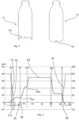
- Fig. 3 shows two representations of a plastic container.
- the left representation shows the geometry of the container before the boxing phase during rinsing.
- the right representation shows a situation after the boxing phase, in which the base 10a of the container was pushed upward to create a kink.
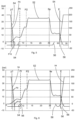
- Fig. 4 shows a first representation of a method not according to the invention.
- Reference numeral 52 refers to the blowing curve or pressure curve.
- the reference symbols P1, Pi, P2, Sp and E or the corresponding vertical lines indicate the respective time periods from which new pressure levels are used.
- the second pressure Pi is also referred to as intermediate blow pressure. It can be seen that starting at a point in time of approximately three seconds, the plastic container is subjected to a specific pressure P1, the pre-blow pressure. At the same time, the stretch rod is moved into the container. Reference numeral 54 indicates the course of the stretch rod movement. Towards the end of the phase in which the first pressure P1 is applied, the rod-like body is retracted slightly, and after a short time, the base part is also moved to an upper position.
- the entire pressure curve preferably has several inflection points (in the mathematical sense, i.e., points at which the second derivative of a corresponding function would change sign).
- the first pressure P1 transitions into the second pressure Pi around a pressure inflection point WP1
- this second pressure Pi in turn transitions into the third pressure P2 around a pressure inflection point WP2.
- the transition from the third pressure P2, also referred to as the finished blowing pressure, to the purging pressure Sp occurs shortly before a sharp drop in pressure, and the transition from the purging pressure Sp to the relief pressure in turn occurs before a sharp drop in pressure.
- Reference numeral 56 accordingly identifies the movement path of the base part.
- the base part remains in the upwardly advanced position throughout the entire phase in which the container is subjected to the third pressure P2.
- the third pressure P2 initially rises to a certain level of approximately 35 bar and remains in this phase for a predetermined period of time, in this case approximately 12 seconds. During this time period, the container is circumferentially formed. After this final blow molding, the container is rinsed (pressure Sp), during which the pressure drops again to a level of approximately 10 bar. Finally, in a final phase E (or during application of the relief pressure E), the container is relieved and the stretch rod is retracted upwards. During this phase, the base part is also reset, as can be seen from the last section of curve 56.
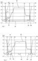
- Fig. 5 shows a further embodiment of the method according to the invention.
- the pressure curve 52 is as already described in the previous methods, i.e., there are no changes here.
- the stretching rod is used as in the Fig. 4 In the embodiment shown, the rod is retracted slightly while the container is still subjected to the first pressure P1.
- Reference symbol P10 indicates the position to which the rod is retracted.
- Reference symbol P0 indicates a further position of the rod.
- the base part is only moved upwards during the rinsing phase or the pressure Sp and is moved back again during the relief phase E.
- the base part remains in an (upper) state directed towards the plastic bottle for the entire duration of the application of the plastic preform or the plastic bottle.
- the pressure curves it can be seen in all designs that they are connected to one another, as mentioned above. In each case, however, the average pressure in the individual phases (pre-blowing, intermediate blowing, and final blowing) is different. This means that the pre-blowing pressure is lower than the average intermediate blowing pressure, and the average intermediate blowing pressure is lower than the final blowing pressure. In other words, the average pressure between the vertical lines P1 and P1 would be lower than the average pressure between the vertical lines P1 and P2, which in turn would be lower than the average pressure between the vertical lines P2 and P3. The average pressure between the lines P3 and P4 is in turn lower than the average pressure between the lines P5 and P6.
- the base part is first advanced onto the plastic preform before or during the application of the second pressure and remains in this upward position until the third pressure P2 is fully applied. Subsequently, in the area between the vertical lines Sp and E, the base part is briefly returned to its starting position and then advanced onto the plastic preform again. According to the invention, this takes place in the area of the unloading phase E. Finally, the base part is moved back to its starting position during the unloading phase.
- the stretch rod movement preferably does not follow these last-described movements of the base part, but remains in a partially retracted position.
- the base part is advanced onto the plastic preform and then retracted again exactly twice. However, it would also be possible for the base part to be advanced onto the plastic preform and then (at least partially) retracted more often than twice, for example three or four times.
- Fig. 7 shows a further design in a variant as shown in Fig. 6 is shown.
- the base part is also moved forward and backward twice, but only after the third pressure P2 has been applied. It can be seen that here the base part is briefly moved toward the plastic preform and immediately returned, before being moved again toward the plastic preform or the now-formed plastic container. In this embodiment, too, the base part is finally moved back to its starting position.
- Fig. 8 shows a further development of the Fig. 6 shown process. It can be seen that here the base part is first fed during the P1 phase and the beginning of the Pi phase. Subsequently, the base part is briefly retracted while the plastic preform is subjected to the third pressure P2 and is fed back onto the plastic preform. According to the invention, the base part is retracted a third time during the rinsing phase Sp, and then fed back onto the plastic preform (or the container already formed at this time) during the relief phase. Thus, the base part is Fig. 8 In the process shown, the blow mold is advanced onto the plastic preform three times and then withdrawn again. This process also allows for better control of the blowing speed. In particular, control is possible by adjusting the second pressure Pi (i.e., the intermediate blow pressure). Container quality can also be improved in this way. Better control of wall thicknesses is also possible.
- the second pressure Pi i.e., the intermediate blow pressure
Landscapes
- Engineering & Computer Science (AREA)
- Manufacturing & Machinery (AREA)
- Mechanical Engineering (AREA)
- Blow-Moulding Or Thermoforming Of Plastics Or The Like (AREA)
Claims (10)
- Procédé destiné à former des préformes en plastique pour en faire des bouteilles en plastique avec les étapes de :- introduction d'une préforme en plastique (10) à dilater dans un moule de soufflage, dans lequel ce moule de soufflage présente au moins deux parties latérales (14) et une partie de fond (18) mobile par rapport à ces parties latérales dans une direction longitudinale (L) de la préforme en plastique (10)- insertion d'un corps (34) en forme de tige à travers un orifice de la préforme en plastique (10) jusqu'à l'intérieur de la préforme en plastique (10)- sollicitation de la préforme en plastique avec une première pression (P1)- sollicitation de la préforme en plastique avec une deuxième pression (Pi), dans lequel cette deuxième pression (Pi) diffère de la première pression (P1) et est plus élevée que la première pression (P1)- sollicitation de la préforme en plastique avec une troisième pression (P2), dans lequel cette troisième pression (P2) diffère de la deuxième pression (Pi) et est plus élevée que la deuxième pression (Pi),caractérisé en ce que
après la sollicitation de la préforme en plastique (10) avec la troisième pression (P2), la partie de fond (18) est présentée, dans la direction longitudinale (L) de la préforme en plastique (10), sur celle-ci. - Procédé selon la revendication 1,
caractérisé en ce que
le corps (34) en forme de tige est retiré au moins partiellement avant ou pendant la présentation de la partie de fond (18). - Procédé selon au moins l'une des revendications précédentes,
caractérisé en ce que
la partie de fond (18) est présentée à une distance qui est supérieure à 5 mm, de préférence supérieure à 10 mm et particulièrement de préférence supérieure à 15 mm et/ou en ce que la partie de fond (18) est présentée à une distance qui est inférieure à 30 mm, de préférence inférieure à 25 mm et particulièrement de préférence inférieure à 20 mm. - Procédé selon au moins l'une des revendications précédentes,
caractérisé en ce que
la préforme en plastique est à nouveau déchargée de la pression après la sollicitation avec la troisième pression (P2). - Procédé selon au moins l'une des revendications précédentes,
caractérisé en ce que
la partie de fond (18) est à nouveau retirée après la sollicitation de la préforme en plastique avec la troisième pression (P2) et de préférence après un rinçage de la préforme en plastique et particulièrement de préférence pendant un déchargement du récipient en plastique usiné hors de la préforme en plastique. - Procédé selon au moins l'une des revendications précédentes,
caractérisé en ce que
le corps en forme de tige est au moins partiellement retiré avant la sollicitation de la préforme en plastique avec la troisième pression (P2). - Procédé selon au moins l'une des revendications précédentes,
caractérisé en ce que
la partie de fond (18) est présentée pendant une durée qui se situe entre 1 sec et 20 sec, de préférence entre 1 sec et 15 sec et de préférence entre 2 sec et 10 sec et particulièrement de préférence entre 2 sec et 5 sec. - Procédé selon au moins l'une des revendications précédentes,
caractérisé en ce que
la deuxième pression est supérieure à 3,5 bar, de préférence supérieure à 5 bar, de préférence supérieure à 7 bar et particulièrement de préférence supérieure à 10 bar et de préférence supérieure à 12 bar et/ou la deuxième pression est inférieure à 20 bar, de préférence inférieure à 18 bar et particulièrement de préférence inférieure à 17 bar. - Procédé selon au moins l'une des revendications précédentes,
caractérisé en ce que
le récipient en plastique est sollicité avec une pression de rinçage (Sp) après la sollicitation avec la troisième pression (P2). - Dispositif destiné à former des préformes en plastique pour en faire des bouteilles en plastique avec au moins un équipement de transport (2) contre lequel sont agencées une pluralité de stations de formage (20), dans lequel chacune de ces stations de formage présente un moule de soufflage, lequel présente respectivement deux parties latérales (14) mobiles l'une par rapport à l'autre pour ouvrir et fermer le moule de soufflage, ainsi qu'une partie de fond (18), dans lequel cette partie de fond (18) est mobile par rapport aux parties latérales (14) dans une direction longitudinale (L) de la préforme en plastique (10) et dans un état fermé du moule de soufflage, et dans lequel le dispositif (1) présente en outre au moins un équipement de sollicitation pour solliciter, avec un milieu sous forme de gaz, les préformes en plastique quant à leur dilatation, ainsi qu'un équipement de commande, lequel commande la sollicitation des préformes en plastique avec le milieu sous forme de gaz de telle sorte que ces dernières soient sollicitées d'abord avec une première pression (P1), puis avec une deuxième pression (Pi) qui est supérieure à la première pression (P1), et enfin avec une troisième pression (P2) qui est supérieure à la deuxième pression (Pi),
caractérisé en ce que
le dispositif présente un équipement d'entraînement (36), lequel est adapté et déterminé pour au moins temporairement déplacer, pendant la sollicitation des préformes en plastique (10), la partie de fond (18) avec celles-ci, dans lequel la partie de fond (18) peut être présentée, après la sollicitation de la préforme en plastique (10) avec la troisième pression (P2), dans la direction longitudinale (L) de la préforme en plastique (10), sur celle-ci.
Applications Claiming Priority (2)
| Application Number | Priority Date | Filing Date | Title |
|---|---|---|---|
| DE102016125586.6A DE102016125586A1 (de) | 2016-12-23 | 2016-12-23 | Verfahren und Vorrichtung zum Blasformen von Behältnissen mit beweglichem Bodenteil |
| PCT/EP2017/082356 WO2018114462A1 (fr) | 2016-12-23 | 2017-12-12 | Procédé et dispositif pour le moulage par soufflage de récipients présentant une partie de fond mobile |
Publications (3)
| Publication Number | Publication Date |
|---|---|
| EP3558631A1 EP3558631A1 (fr) | 2019-10-30 |
| EP3558631B1 EP3558631B1 (fr) | 2021-10-27 |
| EP3558631B2 true EP3558631B2 (fr) | 2025-06-11 |
Family
ID=60812047
Family Applications (1)
| Application Number | Title | Priority Date | Filing Date |
|---|---|---|---|
| EP17821525.7A Active EP3558631B2 (fr) | 2016-12-23 | 2017-12-12 | Procédé et dispositif pour le moulage par soufflage de récipients présentant une partie de fond mobile |
Country Status (5)
| Country | Link |
|---|---|
| US (1) | US11141906B2 (fr) |
| EP (1) | EP3558631B2 (fr) |
| CN (2) | CN110290913B (fr) |
| DE (1) | DE102016125586A1 (fr) |
| WO (1) | WO2018114462A1 (fr) |
Families Citing this family (2)
| Publication number | Priority date | Publication date | Assignee | Title |
|---|---|---|---|---|
| DE102016125586A1 (de) | 2016-12-23 | 2018-06-28 | Krones Aktiengesellschaft | Verfahren und Vorrichtung zum Blasformen von Behältnissen mit beweglichem Bodenteil |
| DE102021128204A1 (de) | 2021-10-28 | 2023-05-04 | Krones Aktiengesellschaft | Verfahren und Vorrichtung zum Umformen von Kunststoffvorformlingen zu Kunststoffbehältnissen mit Verlaufskurvenauswertung |
Family Cites Families (24)
| Publication number | Priority date | Publication date | Assignee | Title |
|---|---|---|---|---|
| US3949034A (en) * | 1972-02-11 | 1976-04-06 | Owens-Illinois, Inc. | Method of making blown plastic containers |
| DE2222535C3 (de) | 1972-05-08 | 1979-10-18 | Heidenreich & Harbeck Zweigniederlassung Der Gildemeister Ag, 2000 Hamburg | Verfahren und Vorrichtung zum Steuern der Einwärtsbewegung eines Stempels einer Blasform beim Herstellen eines Hohlkörpers |
| DE2914938C2 (de) | 1979-04-12 | 1982-11-11 | Mauser-Werke GmbH, 5040 Brühl | Vorrichtung zum Blasformen eines Fasses |
| US4465199A (en) | 1981-06-22 | 1984-08-14 | Katashi Aoki | Pressure resisting plastic bottle |
| SE448967B (sv) | 1983-03-10 | 1987-03-30 | Petainer Sa | Sett och anordning for tillverkning av termoplastbehallare |
| JP3801766B2 (ja) | 1998-01-27 | 2006-07-26 | 株式会社吉野工業所 | ブローエァーの回収方法 |
| US8584879B2 (en) | 2000-08-31 | 2013-11-19 | Co2Pac Limited | Plastic container having a deep-set invertible base and related methods |
| DE202004021780U1 (de) * | 2004-03-25 | 2010-12-09 | Krones Ag | Vorrichtung zum Herstellen eines insbesondere wärmebeständigen Hohlkörpers |
| US7799264B2 (en) | 2006-03-15 | 2010-09-21 | Graham Packaging Company, L.P. | Container and method for blowmolding a base in a partial vacuum pressure reduction setup |
| JP5019810B2 (ja) | 2006-07-18 | 2012-09-05 | 北海製罐株式会社 | 合成樹脂製ボトル及びその製造方法 |
| DE102007015105B4 (de) | 2007-03-29 | 2022-03-10 | Krones Aktiengesellschaft | Vorrichtung zum Blasformen |
| DE102009041013A1 (de) | 2009-09-10 | 2011-03-24 | Krones Ag | Verfahren und Vorrichtung zum Blasformen von Behältern |
| FR2975331B1 (fr) * | 2011-05-19 | 2014-03-07 | Sidel Participations | Procede d'etirage soufflage d'un recipient, comprenant une retraction de la tige d'etirage au cours d'une operation de boxage |
| DE102011110962A1 (de) * | 2011-08-18 | 2013-02-21 | Khs Corpoplast Gmbh | Verfahren und Vorrichtung zur Blasformung von Behältern |
| DE102012110023A1 (de) * | 2012-10-19 | 2014-04-24 | Krones Ag | Blasmaschine mit variablem Zwischendruckniveau |
| FR2998206B1 (fr) * | 2012-11-19 | 2015-01-16 | Sidel Participations | Procede de fabrication de recipients, comprenant une operation retardee de boxage |
| FR2998207B1 (fr) | 2012-11-20 | 2015-01-16 | Sidel Participations | Procede d'etirage soufflage d'un recipient, comprenant une mesure du deplacement de la tige d'etirage au cours d'une operation de boxage |
| EP2764967B1 (fr) | 2013-02-06 | 2015-10-14 | Sidel Participations | Moule pour le soufflage d'un récipient remplissable à chaud à taux d'étirage accrus |
| FR3008337B1 (fr) | 2013-07-09 | 2016-01-22 | Sidel Participations | "procede de formage de recipients comportant des etapes de recyclage du fluide de soufflage au moyen d'un reservoir, la pression dans le reservoir oscillant entre une pression de stockage et une pression de destockage" |
| FR3019486B1 (fr) | 2014-04-02 | 2016-12-23 | Sidel Participations | Procede de fabrication et unite de moulage de recipients a grande course de boxage |
| EP2957515B1 (fr) | 2014-06-18 | 2017-05-24 | Sidel Participations | Récipient doté d'un diaphragme réversible et d'une partie centrale d'épaisseur supérieure |
| FR3029133B1 (fr) | 2014-11-27 | 2016-12-30 | Sidel Participations | Procede de fabrication de recipient a boxage cale sur le soufflage |
| FR3049133B1 (fr) * | 2016-03-15 | 2019-05-03 | Synhapps | Systeme electronique autonome de surveillance de la consommation d'un produit fluide contenu dans un recipient et flacon pulverisateur muni d'un tel systeme |
| DE102016125586A1 (de) | 2016-12-23 | 2018-06-28 | Krones Aktiengesellschaft | Verfahren und Vorrichtung zum Blasformen von Behältnissen mit beweglichem Bodenteil |
-
2016
- 2016-12-23 DE DE102016125586.6A patent/DE102016125586A1/de active Pending
-
2017
- 2017-12-12 CN CN201780079565.5A patent/CN110290913B/zh active Active
- 2017-12-12 EP EP17821525.7A patent/EP3558631B2/fr active Active
- 2017-12-12 WO PCT/EP2017/082356 patent/WO2018114462A1/fr not_active Ceased
- 2017-12-12 CN CN202210115868.0A patent/CN114643693B/zh active Active
- 2017-12-12 US US16/473,219 patent/US11141906B2/en active Active
Also Published As
| Publication number | Publication date |
|---|---|
| CN114643693A (zh) | 2022-06-21 |
| EP3558631A1 (fr) | 2019-10-30 |
| WO2018114462A1 (fr) | 2018-06-28 |
| CN114643693B (zh) | 2024-12-31 |
| US20190315038A1 (en) | 2019-10-17 |
| EP3558631B1 (fr) | 2021-10-27 |
| DE102016125586A1 (de) | 2018-06-28 |
| CN110290913B (zh) | 2022-02-25 |
| CN110290913A (zh) | 2019-09-27 |
| US11141906B2 (en) | 2021-10-12 |
Similar Documents
| Publication | Publication Date | Title |
|---|---|---|
| EP3558633B1 (fr) | Procédé et dispositif pour le moulage par soufflage de contenants à l'aide d'une partie inférieure mobile | |
| EP2218569B1 (fr) | Dispositif de fabrication de récipients en plastique | |
| EP2845716B1 (fr) | Moule de soufflage, machine de formage par soufflage et procédé de formage de préformes en matière plastique en récipients en matière plastique ayant une évacuation d'air | |
| DE102011015666B4 (de) | Verfahren sowie Vorrichtung zur Herstellung von Behältern | |
| EP2740582B1 (fr) | Machine de formage par soufflage et procédé apparenté. | |
| DE2161066B2 (de) | Verfahren und vorrichtung zur herstellung eines hohlkoerpers aus thermoplastischem kunststoff | |
| EP3825097B1 (fr) | Dispositif de formage des préformes en matière plastique pour obtenir des récipients en matière plastique pourvu de soupape proportionnelle | |
| EP2653290B1 (fr) | Machine de formage par soufflage avec refroidissement du sol dans une phase de stabilisation | |
| DE102013103543A1 (de) | Vorrichtung und Verfahren zum Umformen von Kunststoffvorformlingen zu Kunststoffbehältnissen | |
| EP1837156A2 (fr) | Procédé d'extrusion pour préformes en plastique | |
| EP3558631B1 (fr) | Procédé et dispositif pour le moulage par soufflage de récipients présentant une partie de fond mobile | |
| EP3558632B1 (fr) | Procédé et dispositif pour le moulage par soufflage de contenants à l'aide d'une partie inférieure mobile | |
| EP3711925B1 (fr) | Machine de moulage par soufflage pourvu de double clapet anti-retour | |
| EP2272652B1 (fr) | Souffleuse et procédé de fabrication de corps creux | |
| EP2987610B1 (fr) | Remplisseuse de moule destinée à fabriquer et à remplir des récipients en plastique par recyclage de CO2 | |
| EP2987622B1 (fr) | Remplisseuse de moule et procédé de démoulage et de remplissage de récipients | |
| EP2913174A1 (fr) | Machine de formage par soufflage à centrage du fond de moule de soufflage | |
| DE2132674A1 (de) | Verfahren und vorrichtung zum herstellen von hohlkoerpern mit einem halsteil, insbesondere flaschen aus thermoplastischem kunststoff | |
| EP2803469B1 (fr) | Machine de formage par soufflage dotée d'une commande séparée de coussin de pression | |
| EP3088160A1 (fr) | Procede et dispositif de transformation d'ebauches plastiques avec refroidissement de recipient | |
| DE102018119640A1 (de) | Blasformverfahren | |
| DE102014018144A1 (de) | Blasformmaschine mit Zentrierung des Blasformbodens | |
| DE102021130572A1 (de) | Vorrichtung und Verfahren zum Herstellen von Getränkebehältnissen mit verringertem Ausschuss | |
| DE1811452A1 (de) | Verfahren und Vorrichtung zum Herstellen von Hohlkoerpern aus thermoplastischem Kunststoff | |
| WO2018134429A1 (fr) | Procédé pour produire des contenants en matière plastique comprenant des zones de fond mobiles les unes par rapport aux autres, et dispositif de formage correspondant |
Legal Events
| Date | Code | Title | Description |
|---|---|---|---|
| STAA | Information on the status of an ep patent application or granted ep patent |
Free format text: STATUS: UNKNOWN |
|
| STAA | Information on the status of an ep patent application or granted ep patent |
Free format text: STATUS: THE INTERNATIONAL PUBLICATION HAS BEEN MADE |
|
| PUAI | Public reference made under article 153(3) epc to a published international application that has entered the european phase |
Free format text: ORIGINAL CODE: 0009012 |
|
| STAA | Information on the status of an ep patent application or granted ep patent |
Free format text: STATUS: REQUEST FOR EXAMINATION WAS MADE |
|
| 17P | Request for examination filed |
Effective date: 20190723 |
|
| AK | Designated contracting states |
Kind code of ref document: A1 Designated state(s): AL AT BE BG CH CY CZ DE DK EE ES FI FR GB GR HR HU IE IS IT LI LT LU LV MC MK MT NL NO PL PT RO RS SE SI SK SM TR |
|
| AX | Request for extension of the european patent |
Extension state: BA ME |
|
| DAV | Request for validation of the european patent (deleted) | ||
| DAX | Request for extension of the european patent (deleted) | ||
| GRAP | Despatch of communication of intention to grant a patent |
Free format text: ORIGINAL CODE: EPIDOSNIGR1 |
|
| STAA | Information on the status of an ep patent application or granted ep patent |
Free format text: STATUS: GRANT OF PATENT IS INTENDED |
|
| INTG | Intention to grant announced |
Effective date: 20210430 |
|
| TPAC | Observations filed by third parties |
Free format text: ORIGINAL CODE: EPIDOSNTIPA |
|
| GRAJ | Information related to disapproval of communication of intention to grant by the applicant or resumption of examination proceedings by the epo deleted |
Free format text: ORIGINAL CODE: EPIDOSDIGR1 |
|
| GRAL | Information related to payment of fee for publishing/printing deleted |
Free format text: ORIGINAL CODE: EPIDOSDIGR3 |
|
| GRAS | Grant fee paid |
Free format text: ORIGINAL CODE: EPIDOSNIGR3 |
|
| STAA | Information on the status of an ep patent application or granted ep patent |
Free format text: STATUS: REQUEST FOR EXAMINATION WAS MADE |
|
| GRAP | Despatch of communication of intention to grant a patent |
Free format text: ORIGINAL CODE: EPIDOSNIGR1 |
|
| STAA | Information on the status of an ep patent application or granted ep patent |
Free format text: STATUS: GRANT OF PATENT IS INTENDED |
|
| GRAA | (expected) grant |
Free format text: ORIGINAL CODE: 0009210 |
|
| STAA | Information on the status of an ep patent application or granted ep patent |
Free format text: STATUS: THE PATENT HAS BEEN GRANTED |
|
| INTG | Intention to grant announced |
Effective date: 20210915 |
|
| AK | Designated contracting states |
Kind code of ref document: B1 Designated state(s): AL AT BE BG CH CY CZ DE DK EE ES FI FR GB GR HR HU IE IS IT LI LT LU LV MC MK MT NL NO PL PT RO RS SE SI SK SM TR |
|
| REG | Reference to a national code |
Ref country code: GB Ref legal event code: FG4D Free format text: NOT ENGLISH |
|
| REG | Reference to a national code |
Ref country code: CH Ref legal event code: EP |
|
| REG | Reference to a national code |
Ref country code: AT Ref legal event code: REF Ref document number: 1441407 Country of ref document: AT Kind code of ref document: T Effective date: 20211115 |
|
| REG | Reference to a national code |
Ref country code: DE Ref legal event code: R096 Ref document number: 502017011854 Country of ref document: DE |
|
| REG | Reference to a national code |
Ref country code: IE Ref legal event code: FG4D Free format text: LANGUAGE OF EP DOCUMENT: GERMAN |
|
| REG | Reference to a national code |
Ref country code: LT Ref legal event code: MG9D |
|
| REG | Reference to a national code |
Ref country code: NL Ref legal event code: MP Effective date: 20211027 |
|
| PG25 | Lapsed in a contracting state [announced via postgrant information from national office to epo] |
Ref country code: RS Free format text: LAPSE BECAUSE OF FAILURE TO SUBMIT A TRANSLATION OF THE DESCRIPTION OR TO PAY THE FEE WITHIN THE PRESCRIBED TIME-LIMIT Effective date: 20211027 Ref country code: LT Free format text: LAPSE BECAUSE OF FAILURE TO SUBMIT A TRANSLATION OF THE DESCRIPTION OR TO PAY THE FEE WITHIN THE PRESCRIBED TIME-LIMIT Effective date: 20211027 Ref country code: FI Free format text: LAPSE BECAUSE OF FAILURE TO SUBMIT A TRANSLATION OF THE DESCRIPTION OR TO PAY THE FEE WITHIN THE PRESCRIBED TIME-LIMIT Effective date: 20211027 Ref country code: BG Free format text: LAPSE BECAUSE OF FAILURE TO SUBMIT A TRANSLATION OF THE DESCRIPTION OR TO PAY THE FEE WITHIN THE PRESCRIBED TIME-LIMIT Effective date: 20220127 |
|
| PG25 | Lapsed in a contracting state [announced via postgrant information from national office to epo] |
Ref country code: IS Free format text: LAPSE BECAUSE OF FAILURE TO SUBMIT A TRANSLATION OF THE DESCRIPTION OR TO PAY THE FEE WITHIN THE PRESCRIBED TIME-LIMIT Effective date: 20220227 Ref country code: SE Free format text: LAPSE BECAUSE OF FAILURE TO SUBMIT A TRANSLATION OF THE DESCRIPTION OR TO PAY THE FEE WITHIN THE PRESCRIBED TIME-LIMIT Effective date: 20211027 Ref country code: PT Free format text: LAPSE BECAUSE OF FAILURE TO SUBMIT A TRANSLATION OF THE DESCRIPTION OR TO PAY THE FEE WITHIN THE PRESCRIBED TIME-LIMIT Effective date: 20220228 Ref country code: PL Free format text: LAPSE BECAUSE OF FAILURE TO SUBMIT A TRANSLATION OF THE DESCRIPTION OR TO PAY THE FEE WITHIN THE PRESCRIBED TIME-LIMIT Effective date: 20211027 Ref country code: NO Free format text: LAPSE BECAUSE OF FAILURE TO SUBMIT A TRANSLATION OF THE DESCRIPTION OR TO PAY THE FEE WITHIN THE PRESCRIBED TIME-LIMIT Effective date: 20220127 Ref country code: NL Free format text: LAPSE BECAUSE OF FAILURE TO SUBMIT A TRANSLATION OF THE DESCRIPTION OR TO PAY THE FEE WITHIN THE PRESCRIBED TIME-LIMIT Effective date: 20211027 Ref country code: LV Free format text: LAPSE BECAUSE OF FAILURE TO SUBMIT A TRANSLATION OF THE DESCRIPTION OR TO PAY THE FEE WITHIN THE PRESCRIBED TIME-LIMIT Effective date: 20211027 Ref country code: HR Free format text: LAPSE BECAUSE OF FAILURE TO SUBMIT A TRANSLATION OF THE DESCRIPTION OR TO PAY THE FEE WITHIN THE PRESCRIBED TIME-LIMIT Effective date: 20211027 Ref country code: GR Free format text: LAPSE BECAUSE OF FAILURE TO SUBMIT A TRANSLATION OF THE DESCRIPTION OR TO PAY THE FEE WITHIN THE PRESCRIBED TIME-LIMIT Effective date: 20220128 Ref country code: ES Free format text: LAPSE BECAUSE OF FAILURE TO SUBMIT A TRANSLATION OF THE DESCRIPTION OR TO PAY THE FEE WITHIN THE PRESCRIBED TIME-LIMIT Effective date: 20211027 |
|
| REG | Reference to a national code |
Ref country code: DE Ref legal event code: R026 Ref document number: 502017011854 Country of ref document: DE |
|
| PG25 | Lapsed in a contracting state [announced via postgrant information from national office to epo] |
Ref country code: SM Free format text: LAPSE BECAUSE OF FAILURE TO SUBMIT A TRANSLATION OF THE DESCRIPTION OR TO PAY THE FEE WITHIN THE PRESCRIBED TIME-LIMIT Effective date: 20211027 Ref country code: SK Free format text: LAPSE BECAUSE OF FAILURE TO SUBMIT A TRANSLATION OF THE DESCRIPTION OR TO PAY THE FEE WITHIN THE PRESCRIBED TIME-LIMIT Effective date: 20211027 Ref country code: RO Free format text: LAPSE BECAUSE OF FAILURE TO SUBMIT A TRANSLATION OF THE DESCRIPTION OR TO PAY THE FEE WITHIN THE PRESCRIBED TIME-LIMIT Effective date: 20211027 Ref country code: MC Free format text: LAPSE BECAUSE OF FAILURE TO SUBMIT A TRANSLATION OF THE DESCRIPTION OR TO PAY THE FEE WITHIN THE PRESCRIBED TIME-LIMIT Effective date: 20211027 Ref country code: EE Free format text: LAPSE BECAUSE OF FAILURE TO SUBMIT A TRANSLATION OF THE DESCRIPTION OR TO PAY THE FEE WITHIN THE PRESCRIBED TIME-LIMIT Effective date: 20211027 Ref country code: DK Free format text: LAPSE BECAUSE OF FAILURE TO SUBMIT A TRANSLATION OF THE DESCRIPTION OR TO PAY THE FEE WITHIN THE PRESCRIBED TIME-LIMIT Effective date: 20211027 Ref country code: CZ Free format text: LAPSE BECAUSE OF FAILURE TO SUBMIT A TRANSLATION OF THE DESCRIPTION OR TO PAY THE FEE WITHIN THE PRESCRIBED TIME-LIMIT Effective date: 20211027 |
|
| PLBI | Opposition filed |
Free format text: ORIGINAL CODE: 0009260 |
|
| REG | Reference to a national code |
Ref country code: CH Ref legal event code: PL |
|
| PLAX | Notice of opposition and request to file observation + time limit sent |
Free format text: ORIGINAL CODE: EPIDOSNOBS2 |
|
| 26 | Opposition filed |
Opponent name: KHS GMBH Effective date: 20220725 |
|
| REG | Reference to a national code |
Ref country code: BE Ref legal event code: MM Effective date: 20211231 |
|
| GBPC | Gb: european patent ceased through non-payment of renewal fee |
Effective date: 20220127 |
|
| PG25 | Lapsed in a contracting state [announced via postgrant information from national office to epo] |
Ref country code: LU Free format text: LAPSE BECAUSE OF NON-PAYMENT OF DUE FEES Effective date: 20211212 Ref country code: IE Free format text: LAPSE BECAUSE OF NON-PAYMENT OF DUE FEES Effective date: 20211212 Ref country code: GB Free format text: LAPSE BECAUSE OF NON-PAYMENT OF DUE FEES Effective date: 20220127 Ref country code: AL Free format text: LAPSE BECAUSE OF FAILURE TO SUBMIT A TRANSLATION OF THE DESCRIPTION OR TO PAY THE FEE WITHIN THE PRESCRIBED TIME-LIMIT Effective date: 20211027 |
|
| PG25 | Lapsed in a contracting state [announced via postgrant information from national office to epo] |
Ref country code: SI Free format text: LAPSE BECAUSE OF FAILURE TO SUBMIT A TRANSLATION OF THE DESCRIPTION OR TO PAY THE FEE WITHIN THE PRESCRIBED TIME-LIMIT Effective date: 20211027 Ref country code: BE Free format text: LAPSE BECAUSE OF NON-PAYMENT OF DUE FEES Effective date: 20211231 |
|
| PG25 | Lapsed in a contracting state [announced via postgrant information from national office to epo] |
Ref country code: LI Free format text: LAPSE BECAUSE OF NON-PAYMENT OF DUE FEES Effective date: 20211231 Ref country code: CH Free format text: LAPSE BECAUSE OF NON-PAYMENT OF DUE FEES Effective date: 20211231 |
|
| PLBB | Reply of patent proprietor to notice(s) of opposition received |
Free format text: ORIGINAL CODE: EPIDOSNOBS3 |
|
| P01 | Opt-out of the competence of the unified patent court (upc) registered |
Effective date: 20230523 |
|
| PG25 | Lapsed in a contracting state [announced via postgrant information from national office to epo] |
Ref country code: CY Free format text: LAPSE BECAUSE OF FAILURE TO SUBMIT A TRANSLATION OF THE DESCRIPTION OR TO PAY THE FEE WITHIN THE PRESCRIBED TIME-LIMIT Effective date: 20211027 |
|
| PG25 | Lapsed in a contracting state [announced via postgrant information from national office to epo] |
Ref country code: HU Free format text: LAPSE BECAUSE OF FAILURE TO SUBMIT A TRANSLATION OF THE DESCRIPTION OR TO PAY THE FEE WITHIN THE PRESCRIBED TIME-LIMIT; INVALID AB INITIO Effective date: 20171212 |
|
| REG | Reference to a national code |
Ref country code: AT Ref legal event code: MM01 Ref document number: 1441407 Country of ref document: AT Kind code of ref document: T Effective date: 20221212 |
|
| PG25 | Lapsed in a contracting state [announced via postgrant information from national office to epo] |
Ref country code: AT Free format text: LAPSE BECAUSE OF NON-PAYMENT OF DUE FEES Effective date: 20221212 |
|
| PG25 | Lapsed in a contracting state [announced via postgrant information from national office to epo] |
Ref country code: MK Free format text: LAPSE BECAUSE OF FAILURE TO SUBMIT A TRANSLATION OF THE DESCRIPTION OR TO PAY THE FEE WITHIN THE PRESCRIBED TIME-LIMIT Effective date: 20211027 Ref country code: AT Free format text: LAPSE BECAUSE OF NON-PAYMENT OF DUE FEES Effective date: 20221212 |
|
| PG25 | Lapsed in a contracting state [announced via postgrant information from national office to epo] |
Ref country code: TR Free format text: LAPSE BECAUSE OF FAILURE TO SUBMIT A TRANSLATION OF THE DESCRIPTION OR TO PAY THE FEE WITHIN THE PRESCRIBED TIME-LIMIT Effective date: 20211027 |
|
| PG25 | Lapsed in a contracting state [announced via postgrant information from national office to epo] |
Ref country code: MT Free format text: LAPSE BECAUSE OF FAILURE TO SUBMIT A TRANSLATION OF THE DESCRIPTION OR TO PAY THE FEE WITHIN THE PRESCRIBED TIME-LIMIT Effective date: 20211027 |
|
| PUAH | Patent maintained in amended form |
Free format text: ORIGINAL CODE: 0009272 |
|
| STAA | Information on the status of an ep patent application or granted ep patent |
Free format text: STATUS: PATENT MAINTAINED AS AMENDED |
|
| 27A | Patent maintained in amended form |
Effective date: 20250611 |
|
| AK | Designated contracting states |
Kind code of ref document: B2 Designated state(s): AL AT BE BG CH CY CZ DE DK EE ES FI FR GB GR HR HU IE IS IT LI LT LU LV MC MK MT NL NO PL PT RO RS SE SI SK SM TR |
|
| REG | Reference to a national code |
Ref country code: DE Ref legal event code: R102 Ref document number: 502017011854 Country of ref document: DE |
|
| PGFP | Annual fee paid to national office [announced via postgrant information from national office to epo] |
Ref country code: DE Payment date: 20251104 Year of fee payment: 9 |
|
| PGFP | Annual fee paid to national office [announced via postgrant information from national office to epo] |
Ref country code: IT Payment date: 20251121 Year of fee payment: 9 |
|
| PGFP | Annual fee paid to national office [announced via postgrant information from national office to epo] |
Ref country code: FR Payment date: 20251110 Year of fee payment: 9 |
|
| PGFP | Annual fee paid to national office [announced via postgrant information from national office to epo] |
Ref country code: AT Payment date: 20260410 Year of fee payment: 5 |