EP3558785B1 - Ensemble d'attelage, en particulier pour un véhicule ferroviaire - Google Patents
Ensemble d'attelage, en particulier pour un véhicule ferroviaire Download PDFInfo
- Publication number
- EP3558785B1 EP3558785B1 EP17786910.4A EP17786910A EP3558785B1 EP 3558785 B1 EP3558785 B1 EP 3558785B1 EP 17786910 A EP17786910 A EP 17786910A EP 3558785 B1 EP3558785 B1 EP 3558785B1
- Authority
- EP
- European Patent Office
- Prior art keywords
- coupling rod
- coupling
- bearing block
- bearing
- supporting structure
- Prior art date
- Legal status (The legal status is an assumption and is not a legal conclusion. Google has not performed a legal analysis and makes no representation as to the accuracy of the status listed.)
- Active
Links
Images


Classifications
-
- B—PERFORMING OPERATIONS; TRANSPORTING
- B61—RAILWAYS
- B61G—COUPLINGS; DRAUGHT AND BUFFING APPLIANCES
- B61G9/00—Draw-gear
- B61G9/20—Details; Accessories
- B61G9/22—Supporting framework, e.g. cradles; Spring housings
-
- B—PERFORMING OPERATIONS; TRANSPORTING
- B61—RAILWAYS
- B61G—COUPLINGS; DRAUGHT AND BUFFING APPLIANCES
- B61G7/00—Details or accessories
- B61G7/10—Mounting of the couplings on the vehicle
Definitions
- the present invention relates to a clutch arrangement, in particular for a rail vehicle, according to the preamble of claim 1.
- FIG. 7 A previously known in practice generic clutch assembly is shown schematically in figure 7 shown.
- a coupling rod 1 which extends along a longitudinal axis 2 and carries a coupling head 3 in the region of a first axial end, is held in the bearing block 4 on the car body of a rail vehicle, not shown.
- a support structure 7 is provided, which supports the coupling rod 1 from below by means of a supporting spring 16 .
- the support spring 16 keeps the coupling rod 1 at the appropriate height because of its pretension, and because of its spring reserve it allows the necessary up and down movements.
- an opening for the bearing block 4 is provided in a base plate 9, which is attached to the car body.
- This opening is sufficiently large that the coupling rod 1 also fits through the opening in the event of an overload in the longitudinal direction, ie in the direction of the longitudinal axis 2 .
- Such an overload occurs when the rail vehicle collides with an obstacle and is also referred to as a crash.
- An energy dissipation element 8 is provided behind said opening, which deforms in the longitudinal direction when the overload occurs and thereby absorbs at least part of the excess force in the direction of the longitudinal axis 2 .
- the coupling rod 1 can at least partially slip through the opening of the base plate 9 and the connection to the support structure 7 or the support spring 16 is separated, for example by shearing.
- the support structure 7 occupies a comparatively large space below the coupling rod 1 and requires an additional bearing block 17 with which it is connected in an articulated manner to the base plate 9 and is carried by it.
- connection of the support is also an example in JP 2012-81934 A played back.
- EP 2862 777A1 and CN 105083318A disclose versions with the arrangement of the support below the coupling rod and connection.
- An embodiment of a support with the features from the preamble of claim 1 is from WO 2006/117045 A1 known.
- the carrier structure is designed as an element that completely encloses the coupling rod in the circumferential direction and over a partial area in the longitudinal direction.
- the present invention is based on the object of improving the generic clutch arrangement shown in such a way that the support structure takes up less space outside the clutch rod, advantageously has a lower weight and, in particular, changes the power flow as little as possible in the event of an overload and advantageously improves compatibility with the described energy consumption guaranteed.
- a coupling arrangement according to the invention which is particularly suitable for a rail vehicle but can also be used in other vehicles, the coupling arrangement being used, for example, to couple two rail vehicle parts to one another with corresponding coupling arrangements or coupling arrangements that work together, has a coupling rod which extends along a longitudinal axis and carries a coupling head in the region of a first axial end.
- a bearing block is provided, to which the coupling rod is connected in an articulated manner about a vertical axis with a second axial end arranged opposite to the first axial end.
- Connected in an articulated manner about a vertical axis means in particular that the connection creates a mechanically at least essentially rigid coupling in the direction of the longitudinal axis between the coupling rod and the bearing block, possibly apart from possible elastic deflections in particular, but at the same time a sufficiently large angular deflection of the coupling rod relative to the Bearing block and in particular an energy-absorbing element adjoining this and/or compared to a base plate enclosing the bearing block, so that the coupling rod can swing out to the side when cornering.
- a bearing is provided between the pedestal and the drawbar, configured to allow at least limited movement between the drawbar and the pedestal in the vertical direction. This can also be used to achieve height compensation. The movement is achieved, for example, by an elastic bearing. Additionally or alternatively, the bearing block is already movable in the vertical direction.
- a support structure which elastically supports the coupling rod against movement in the vertical direction in order to ensure the aforementioned holding of the coupling rod at the correct height.
- the support structure is positioned in the vertical direction at least predominantly at the level of the bearing block and/or the coupling rod, essentially coaxially with the longitudinal axis. This means that the majority of the support structure protrudes in the vertical direction only slightly beyond the coupling rod, for example by a maximum of half or a third of the way diameter of the coupling rod. It is also possible for the support structure to cling even more closely to the coupling rod, so that the support structure protrudes, for example, by only a quarter of the diameter or less beyond the coupling rod.
- the above statements relate at least to a side plan view in the horizontal direction of the coupling rod.
- the coupling rod is positioned at least substantially coaxially with the longitudinal axis, which means that the central axis or longitudinal axis of the support structure is arranged close to the longitudinal axis of the coupling rod, in particular runs within the outer circumference of the coupling rod, for example with a maximum distance of half a Radius of the tie rod or less, substantially no additional space outside the tie rod is blocked by the support structure.
- the support structure is therefore largely not arranged eccentrically to the coupling rod.
- the coupling arrangement is free of a support structure that is supported in an articulated manner in the radial direction of the coupling rod exclusively on one side outside of the coupling rod, whereby the term supported is to be understood as meaning any suspension of the corresponding component, here the support structure, in which the weight forces of the component and possibly on the Operating forces acting on the component are absorbed by the supporting element, for example by the bearing block or a base plate which is fastened, for example, to the car body.
- the support structure extends above and below the coupling rod and/or above and below the bearing, ie both in a plane above the coupling rod or the bearing and a plane below the coupling rod or the bearing. It goes without saying that the support structure is generally not only provided with planar components, but also advantageously extends in a curved manner around the coupling rod.
- the support structure is pivotally connected to and supported by the bearing block.
- the supporting structure is carried exclusively by the bearing block.
- the support structure is connected to the bearing block in an articulated manner about the same vertical axis as the coupling rod.
- the bearing block is advantageously connected axially to a deformable energy-absorbing element, which in particular has a tubular shape.
- a base plate enclosing the bearing block and/or the energy dissipation element is provided, which is set up to connect the coupling arrangement to a car body of the rail vehicle or to another vehicle component.
- the support structure is articulated, in particular articulated about said vertical axis, to the baseplate and is supported, in particular exclusively, by it.
- the support structure is articulated, in particular articulated about said vertical axis, to the baseplate and is supported, in particular exclusively, by it.
- the support structure is connected in an articulated manner to the bearing block and/or the base plate above and below the coupling rod and/or the bearing and is carried by the corresponding component.
- the support structure has a carrier surrounding the coupling rod over its circumference and at least two lateral guides connected to the carrier, the lateral guides enclosing the coupling rod between them in the horizontal direction.
- the lateral guides can advantageously be connected to one another via a crossbar which runs underneath the coupling rod and supports the coupling rod from below.
- the lateral guides are rigidly connected to the support and the crossbar is elastically connected to the lateral guides, at least in the vertical direction.
- two columns are provided which stand upright on the crossbeam, which are surrounded by the lateral guides over their circumference and are supported in the lateral guides by means of a spring element.
- the bearing can be designed, for example, as a spherical bearing.
- the bearing is designed as an elastic bearing, in particular as a rubber-metal bearing.
- a comparatively wide up and down movement of the coupling rod can be made possible in particular by the illustrated embodiment with the two lateral guides.
- the two lateral guides also contribute to the high bending resistance moment. However, they at least contribute to a more favorable introduction of force into the structure by positively influencing the bending resistance moment in the transition between the guides and the carrier of the support structure.
- the lateral guides have a round, particularly cylindrical surface on the outside and are more or less closely attached to the coupling rod snuggly, a comparatively high rigidity is also achieved in the transverse direction.
- the rigidity in the transverse direction results from the overall curved shape of the carrier of the support structure, with the guides also having the mentioned influence on the rigidity.
- the necessary installation space can still be kept small and a particularly high degree of rigidity can be achieved.
- the support structure can be less clinging to the coupling rod, so that in the event of a crash (overload) a smooth slipping of the coupling rod through the base plate and the support structure is ensured.
- the embodiment allows a comparatively closed form of the support structure, which encloses the coupling rod.
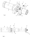
- the support structure 7 connects particularly closely to the coupling rod 1 from the outside. Furthermore, the components of the support structure 7 are essentially positioned coaxially to the coupling rod 1 or its longitudinal axis 2 .
- the coupling rod 1 is movably connected to the bearing block 4 via the spherical elastic bearing 6 .
- the mobility is achieved by the articulated connection around the vertical axis 5 and also by the elasticity of the bearing 6.
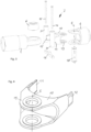
- the bearing block 4 has a tubular structure with a connecting yoke and the coupling rod 1 has in the region of the second axial end has a bearing ring, in which the bearing 6 is introduced, a pin 18 also being provided, which is guided through the joint yoke and the bearing 6 in order to form the desired rotational mobility about the vertical axis 5.
- the bearing block 4 is connected to an energy dissipation element 8 which is positioned coaxially with the coupling rod 1 .
- the bearing block 4 is also surrounded by the base plate 9 on its outer circumference, such that in the event of a crash, the bearing block 4 and possibly the coupling rod 1 can be pushed through the base plate 9 in the direction of the energy dissipation element 8 .
- the support structure 7 is also connected in an articulated manner to the bearing block 4 via the same vertical axis 5, here also by means of the pin 18.
- the support structure 7 has a carrier 10 for this purpose, which has a basic shape closed around the longitudinal axis 2 with an axially connected yoke 19 has, which engages in the yoke of the bearing block 4 and is penetrated by the pin 18 accordingly.
- the carrier 10 has two lateral guides 11, 12 connected in the region of the axial end opposite the joint fork 19, which are provided with hollow cylinders 20, 21 and are connected to one another via the crossbeam 13 supporting the coupling rod 1 from below.
- crossbeam 13 On the crossbeam 13 are two columns 14, 15, for example formed by screws, which are enclosed by the hollow cylinders 20, 21 and are elastically supported in relation to the hollow cylinders 20, 21, so that an elastic springing up and down of the coupling rod 1 in relation to the carrier 10 is made possible.
- the carrier 10 is connected here with the joint yoke 19 outside the joint yoke of the bearing block 4 in an articulated manner via the vertical axis 5 to the base plate 9 . This can be done by means of the pin 18 or via its own pin.
- the carrier 10 does not fit through the opening in the base plate 9, so that in the event of a crash, the coupling tube 1 is separated from the support structure 7, here the crossbeam 13. Accordingly, it is not necessary to separate the lateral guides 11, 12 or the hollow cylinders 20, 21 from the carrier 10.
Landscapes
- Engineering & Computer Science (AREA)
- Mechanical Engineering (AREA)
- Vibration Dampers (AREA)
- Vehicle Body Suspensions (AREA)
- Vibration Prevention Devices (AREA)
- Fittings On The Vehicle Exterior For Carrying Loads, And Devices For Holding Or Mounting Articles (AREA)
Claims (12)
- Agencement d'attelage, notamment pour un véhicule ferroviaire,1.1 avec une barre d'attelage (1), qui s'étend le long d'un axe longitudinal (2) et qui porte une tête d'attelage (3) dans la zone d'une première extrémité axiale ;1.2 avec un bloc de palier (4), auquel la barre d'attelage (1) est raccordée de manière articulée autour d'un axe vertical (5) par une deuxième extrémité axiale agencée à l'opposé de la première extrémité axiale ;1.3 avec un palier (6) entre le bloc de palier (4) et la barre d'attelage (1), qui est adapté pour permettre au moins un mouvement limité entre la barre d'attelage (1) et le bloc de palier (4) dans la direction verticale, et/ou avec un montage du bloc de palier (4) mobile dans la direction verticale ;1.4 avec une structure de soutien (7), qui soutient élastiquement la barre d'attelage (1) contre le mouvement dans la direction verticale ;1.5 la structure de soutien (7) étant positionnée dans la direction verticale au moins principalement à hauteur du bloc de palier (4) et/ou de la barre d'attelage (1) essentiellement coaxialement à l'axe longitudinal (2) et la structure de soutien (7) étant raccordée de manière articulée au bloc de palier (4) au-dessus et au-dessous de la barre d'attelage (1) et/ou du palier (6) et étant portée par celui-ci ;caractérisé en ce quele bloc de palier (4) présente une fourche articulée, un tourillon (18) étant prévu, lequel est guidé à travers la fourche articulée et le palier (6), et la structure de soutien (7) présentant un support (10), qui présente une forme de base fermée autour de l'axe longitudinal (2) avec une fourche articulée (19) se raccordant axialement, qui s'engage dans la fourche articulée du bloc de palier (4) et qui est traversée par le tourillon (18), et le support (10) présentant deux guides latéraux (11, 12) raccordés dans la zone de l'extrémité axiale opposée à la fourche articulée (19), les guides latéraux (11, 12) enserrant entre eux la barre d'attelage (1) dans la direction horizontale et étant reliés entre eux par l'intermédiaire d'une traverse (13) s'étendant au-dessous de la barre d'attelage (1), soutenant la barre d'attelage (1) par le bas et raccordée élastiquement aux guides latéraux (11, 12) au moins dans la direction verticale.
- Agencement d'attelage, notamment pour un véhicule ferroviaire,2.1 avec une barre d'attelage (1), qui s'étend le long d'un axe longitudinal (2) et qui porte une tête d'attelage (3) dans la zone d'une première extrémité axiale ;2.2 avec un bloc de palier (4), auquel la barre d'attelage (1) est raccordée de manière articulée autour d'un axe vertical (5) par une deuxième extrémité axiale agencée à l'opposé de la première extrémité axiale ;2.3 avec un palier (6) entre le bloc de palier (4) et la barre d'attelage (1), qui est adapté pour permettre au moins un mouvement limité entre la barre d'attelage (1) et le bloc de palier (4) dans la direction verticale, et/ou avec un montage du bloc de palier (4) mobile dans la direction verticale ;2.4 avec une structure de soutien (7), qui soutient élastiquement la barre d'attelage (1) contre le mouvement dans la direction verticale ;2.5 la structure de soutien (7) étant positionnée dans la direction verticale au moins principalement à hauteur du bloc de palier (4) et/ou de la barre d'attelage (1) coaxialement à l'axe longitudinal (2) ;2.6 caractérisé en ce que le bloc de palier (4) est raccordé axialement à un élément d'absorption d'énergie déformable (8) et en ce qu'une plaque de base (9) entourant le bloc de palier (4) et/ou l'élément d'absorption d'énergie (8) est prévu, qui est adaptée pour raccorder de manière portante l'agencement d'attelage à une caisse du véhicule ferroviaire ou à un autre composant de véhicule, la structure de soutien (7) étant raccordée de manière articulée à la plaque de base (9) au-dessus et au-dessous de la barre d'attelage (1) et/ou du palier (6) et étant portée exclusivement par celle-ci.
- Agencement d'attelage selon la revendication 1 ou 2, caractérisé en ce que la structure de soutien (7) s'étend au-dessus et au-dessous de la barre d'attelage (1) et/ou au-dessus et au-dessous du palier (6).
- Agencement d'attelage selon la revendication 1, caractérisé en ce que la structure de soutien (7) est raccordée de manière articulée au bloc de palier (4) autour du même axe vertical (5) que la barre d'attelage (1) .
- Agencement d'attelage selon la revendication 2, caractérisé en ce que la structure de soutien (7) est raccordée de manière articulée, notamment de manière articulée autour de l'axe vertical (5), à la plaque de base (9) et est portée par celle-ci.
- Agencement d'attelage selon l'une quelconque des revendications 1, 3 ou 4, caractérisé en ce que la structure de soutien (7) présente un support (10) entourant la barre d'attelage (1) sur sa circonférence et au moins deux guides latéraux (11, 12) raccordés au support (10), les guides latéraux (11, 12) enserrant entre eux la barre d'attelage (1) dans la direction horizontale.
- Agencement d'attelage selon la revendication 6, caractérisé en ce que les guides latéraux (11, 12) sont reliés entre eux par l'intermédiaire d'une traverse (13) s'étendant au-dessous de la barre d'attelage (1), soutenant la barre d'attelage (1) par le bas.
- Agencement d'attelage selon la revendication 7, caractérisé en ce que les guides latéraux (11, 12) sont raccordés de manière rigide au support (10) et la traverse (13) est raccordée élastiquement aux guides latéraux (11, 12) au moins dans la direction verticale.
- Agencement d'attelage selon la revendication 1 ou 8, caractérisé en ce que deux colonnes (14, 15) qui se dressent sur la traverse (13) sont prévues, qui sont entourées par les guides latéraux (11, 12) sur leur circonférence et qui sont portées dans les guides latéraux (11, 12) au moyen d'un élément de ressort.
- Agencement d'attelage selon l'une quelconque des revendications 1 à 9, caractérisé en ce que le palier (6) est réalisé sous forme de palier sphérique.
- Agencement d'attelage selon l'une quelconque des revendications 1 à 10, caractérisé en ce que le palier (6) est réalisé sous forme de palier élastique, notamment sous forme de palier en caoutchouc-métal.
- Agencement d'attelage selon l'une quelconque des revendications 1 à 11, caractérisé en ce que l'agencement d'attelage est exempt d'une structure de soutien portée de manière articulée exclusivement d'un côté à l'extérieur de la barre d'attelage (1) dans la direction radiale de la barre d'attelage (1), notamment portée de manière articulée sur le bloc de palier (4) ou la plaque de base (9).
Applications Claiming Priority (2)
| Application Number | Priority Date | Filing Date | Title |
|---|---|---|---|
| DE102016125087.2A DE102016125087A1 (de) | 2016-12-21 | 2016-12-21 | Kupplungsanordnung, insbesondere für ein Schienenfahrzeug |
| PCT/EP2017/076686 WO2018114087A1 (fr) | 2016-12-21 | 2017-10-19 | Ensemble d'attelage, en particulier pour un véhicule ferroviaire |
Publications (2)
| Publication Number | Publication Date |
|---|---|
| EP3558785A1 EP3558785A1 (fr) | 2019-10-30 |
| EP3558785B1 true EP3558785B1 (fr) | 2023-04-19 |
Family
ID=60138380
Family Applications (1)
| Application Number | Title | Priority Date | Filing Date |
|---|---|---|---|
| EP17786910.4A Active EP3558785B1 (fr) | 2016-12-21 | 2017-10-19 | Ensemble d'attelage, en particulier pour un véhicule ferroviaire |
Country Status (7)
| Country | Link |
|---|---|
| US (1) | US11472448B2 (fr) |
| EP (1) | EP3558785B1 (fr) |
| CN (1) | CN110072757B (fr) |
| DE (1) | DE102016125087A1 (fr) |
| HU (1) | HUE062328T2 (fr) |
| PL (1) | PL3558785T3 (fr) |
| WO (1) | WO2018114087A1 (fr) |
Families Citing this family (6)
| Publication number | Priority date | Publication date | Assignee | Title |
|---|---|---|---|---|
| CN110304097B (zh) * | 2019-07-25 | 2020-05-05 | 中车青岛四方车辆研究所有限公司 | 缓冲装置、钩缓装置及轨道列车 |
| CN110745158A (zh) * | 2019-11-27 | 2020-02-04 | 常州中车铁马科技实业有限公司 | 支撑机构及具有其的对中装置 |
| CN115697811A (zh) * | 2020-06-08 | 2023-02-03 | 德尔纳库普勒斯股份公司 | 用于轨道车辆的联接器和具有联接器的轨道车辆 |
| CN111891168B (zh) * | 2020-07-20 | 2024-06-28 | 中车长春轨道客车股份有限公司 | 一种新型地铁车辆密接式自动车钩防误解钩装置 |
| CN113071528A (zh) * | 2021-04-26 | 2021-07-06 | 大连交通大学 | 柔性抗磨耗车钩托梁装置 |
| EP4653286A1 (fr) * | 2024-05-24 | 2025-11-26 | Voith Patent GmbH | Ensemble embrayage |
Citations (1)
| Publication number | Priority date | Publication date | Assignee | Title |
|---|---|---|---|---|
| EP2862777B1 (fr) * | 2012-06-13 | 2019-06-19 | CRRC Qingdao Sifang Rolling Stock Research Institute Co., Ltd. | Système de suspension installé à l'avant possédant une protection de surcharge |
Family Cites Families (8)
| Publication number | Priority date | Publication date | Assignee | Title |
|---|---|---|---|---|
| DE3015291A1 (de) * | 1980-04-21 | 1982-01-21 | Bergische Stahl-Industrie, 5630 Remscheid | Mittelpufferkupplung, insbesondere fuer schienenfahrzeuge |
| EP1719684B1 (fr) * | 2005-05-03 | 2007-08-15 | Voith Turbo Scharfenberg GmbH & Co. KG | Attelage central pour véhicules ferroviaires |
| PT1955918E (pt) * | 2007-02-08 | 2009-07-16 | Voith Patent Gmbh | Engate central automático de amortecimento |
| JP5307104B2 (ja) * | 2010-10-14 | 2013-10-02 | 株式会社日本製鋼所 | 連結装置 |
| CN102632906B (zh) * | 2012-04-17 | 2014-09-10 | 青岛思锐科技有限公司 | 带过载保护的紧凑式缓冲器 |
| DE102016207256A1 (de) * | 2015-04-29 | 2016-11-03 | Voith Patent Gmbh | Anlenkung zum gelenkigen Verbinden eines wagenkastenseitigen Endbereiches einer Kupplungsstange mit einem Wagenkasten |
| CN105083318B (zh) * | 2015-09-28 | 2016-09-14 | 青岛思锐科技有限公司 | 车钩弹簧垂向支撑装置 |
| CH716577B1 (de) * | 2019-09-12 | 2023-08-31 | Faiveley Transp Schwab Ag | Anlenkungseinrichtung für eine Kupplung, insbesondere eines Schienenfahrzeugs. |
-
2016
- 2016-12-21 DE DE102016125087.2A patent/DE102016125087A1/de not_active Ceased
-
2017
- 2017-10-19 EP EP17786910.4A patent/EP3558785B1/fr active Active
- 2017-10-19 HU HUE17786910A patent/HUE062328T2/hu unknown
- 2017-10-19 PL PL17786910.4T patent/PL3558785T3/pl unknown
- 2017-10-19 WO PCT/EP2017/076686 patent/WO2018114087A1/fr not_active Ceased
- 2017-10-19 CN CN201780077962.9A patent/CN110072757B/zh active Active
-
2019
- 2019-06-20 US US16/447,534 patent/US11472448B2/en active Active
Patent Citations (1)
| Publication number | Priority date | Publication date | Assignee | Title |
|---|---|---|---|---|
| EP2862777B1 (fr) * | 2012-06-13 | 2019-06-19 | CRRC Qingdao Sifang Rolling Stock Research Institute Co., Ltd. | Système de suspension installé à l'avant possédant une protection de surcharge |
Also Published As
| Publication number | Publication date |
|---|---|
| CN110072757B (zh) | 2021-08-31 |
| HUE062328T2 (hu) | 2023-10-28 |
| CN110072757A (zh) | 2019-07-30 |
| US11472448B2 (en) | 2022-10-18 |
| PL3558785T3 (pl) | 2023-08-07 |
| DE102016125087A1 (de) | 2018-06-21 |
| EP3558785A1 (fr) | 2019-10-30 |
| WO2018114087A1 (fr) | 2018-06-28 |
| US20190300027A1 (en) | 2019-10-03 |
Similar Documents
| Publication | Publication Date | Title |
|---|---|---|
| EP3558785B1 (fr) | Ensemble d'attelage, en particulier pour un véhicule ferroviaire | |
| EP3303098B1 (fr) | Système de suspension | |
| DE102015217727A1 (de) | Anschlagkappe | |
| DE102017215112A1 (de) | Schwingungsdämpfer in der Radaufhängung eines Fahrzeugs | |
| WO2017102197A1 (fr) | Dispositif à appuis oscillants de support de moteur | |
| DE102009030633A1 (de) | Achseinbindung für gefederte Fahrzeugachsen sowie Platte zum Einbinden einer Fahrzeugachse | |
| DE4129797C2 (de) | Schwingungstilger | |
| EP3303018B1 (fr) | Ensemble de train de suspension pour un véhicule | |
| DE10019643C2 (de) | Aufhängungsanordnung für eine dynamisch beanspruchte Abgasanlage | |
| DE10338625A1 (de) | Einzelradaufhängung mit einem gekrümmten Lenkerarm | |
| EP3130489A2 (fr) | Suspension de roue pour un véhicule automobile | |
| DE3239006A1 (de) | Fahrzeug mit einem um eine waagerechte achse verschwenkbaren koerperteil, der durch eine hydropneumatische aufhaengung abgestuetzt ist | |
| EP1897776B1 (fr) | Bogie | |
| EP3152094A1 (fr) | Véhicule ferroviaire avec accouplement disposé dans la zone de son côté avant | |
| DE3405173A1 (de) | Radaufhaengung fuer kraftfahrzeuge | |
| DE102020123061B4 (de) | Federelement und Fahrzeugsitz mit Federelement | |
| DE102018006572B4 (de) | Fahrzeugaufhängungsanordnung für mindestens eine Radachse | |
| DE102017200867B4 (de) | Lenkanordnung für ein Fahrzeug | |
| DE60003244T2 (de) | Vorrichtung für eine MacPherson-Typ-Fahrzeugaufhängung | |
| DE1655104B2 (de) | Vorrichtung zur Anlenkung eines als Achsträger dienenden Hilfsrahmens an der Karosserie oder dem Hauptrahmen eines Fahrzeugs | |
| EP2230107B1 (fr) | Suspension de roue pour un véhicule terrestre | |
| EP3390203A1 (fr) | Véhicule doté d'un réservoir sous pression porteur | |
| DE202025101982U1 (de) | Aufhängevorrichtung | |
| DE19748250A1 (de) | Starrachsanordnung | |
| EP3031636A1 (fr) | Module de support de roue |
Legal Events
| Date | Code | Title | Description |
|---|---|---|---|
| STAA | Information on the status of an ep patent application or granted ep patent |
Free format text: STATUS: UNKNOWN |
|
| STAA | Information on the status of an ep patent application or granted ep patent |
Free format text: STATUS: THE INTERNATIONAL PUBLICATION HAS BEEN MADE |
|
| PUAI | Public reference made under article 153(3) epc to a published international application that has entered the european phase |
Free format text: ORIGINAL CODE: 0009012 |
|
| STAA | Information on the status of an ep patent application or granted ep patent |
Free format text: STATUS: REQUEST FOR EXAMINATION WAS MADE |
|
| 17P | Request for examination filed |
Effective date: 20190722 |
|
| AK | Designated contracting states |
Kind code of ref document: A1 Designated state(s): AL AT BE BG CH CY CZ DE DK EE ES FI FR GB GR HR HU IE IS IT LI LT LU LV MC MK MT NL NO PL PT RO RS SE SI SK SM TR |
|
| AX | Request for extension of the european patent |
Extension state: BA ME |
|
| RIN1 | Information on inventor provided before grant (corrected) |
Inventor name: KOLSHORN, KAY UWE Inventor name: SCHIPMANN, RALF Inventor name: JOHANNSEN, ERIK |
|
| RAP1 | Party data changed (applicant data changed or rights of an application transferred) |
Owner name: VOITH PATENT GMBH |
|
| DAV | Request for validation of the european patent (deleted) | ||
| DAX | Request for extension of the european patent (deleted) | ||
| STAA | Information on the status of an ep patent application or granted ep patent |
Free format text: STATUS: EXAMINATION IS IN PROGRESS |
|
| 17Q | First examination report despatched |
Effective date: 20210426 |
|
| GRAP | Despatch of communication of intention to grant a patent |
Free format text: ORIGINAL CODE: EPIDOSNIGR1 |
|
| STAA | Information on the status of an ep patent application or granted ep patent |
Free format text: STATUS: GRANT OF PATENT IS INTENDED |
|
| INTG | Intention to grant announced |
Effective date: 20221108 |
|
| GRAS | Grant fee paid |
Free format text: ORIGINAL CODE: EPIDOSNIGR3 |
|
| GRAA | (expected) grant |
Free format text: ORIGINAL CODE: 0009210 |
|
| STAA | Information on the status of an ep patent application or granted ep patent |
Free format text: STATUS: THE PATENT HAS BEEN GRANTED |
|
| AK | Designated contracting states |
Kind code of ref document: B1 Designated state(s): AL AT BE BG CH CY CZ DE DK EE ES FI FR GB GR HR HU IE IS IT LI LT LU LV MC MK MT NL NO PL PT RO RS SE SI SK SM TR |
|
| REG | Reference to a national code |
Ref country code: GB Ref legal event code: FG4D Free format text: NOT ENGLISH |
|
| REG | Reference to a national code |
Ref country code: DE Ref legal event code: R096 Ref document number: 502017014638 Country of ref document: DE |
|
| REG | Reference to a national code |
Ref country code: CH Ref legal event code: EP |
|
| REG | Reference to a national code |
Ref country code: IE Ref legal event code: FG4D Free format text: LANGUAGE OF EP DOCUMENT: GERMAN |
|
| REG | Reference to a national code |
Ref country code: AT Ref legal event code: REF Ref document number: 1560996 Country of ref document: AT Kind code of ref document: T Effective date: 20230515 |
|
| P01 | Opt-out of the competence of the unified patent court (upc) registered |
Effective date: 20230613 |
|
| REG | Reference to a national code |
Ref country code: SE Ref legal event code: TRGR |
|
| REG | Reference to a national code |
Ref country code: LT Ref legal event code: MG9D |
|
| REG | Reference to a national code |
Ref country code: NL Ref legal event code: MP Effective date: 20230419 |
|
| PG25 | Lapsed in a contracting state [announced via postgrant information from national office to epo] |
Ref country code: NL Free format text: LAPSE BECAUSE OF FAILURE TO SUBMIT A TRANSLATION OF THE DESCRIPTION OR TO PAY THE FEE WITHIN THE PRESCRIBED TIME-LIMIT Effective date: 20230419 |
|
| REG | Reference to a national code |
Ref country code: HU Ref legal event code: AG4A Ref document number: E062328 Country of ref document: HU |
|
| PG25 | Lapsed in a contracting state [announced via postgrant information from national office to epo] |
Ref country code: PT Free format text: LAPSE BECAUSE OF FAILURE TO SUBMIT A TRANSLATION OF THE DESCRIPTION OR TO PAY THE FEE WITHIN THE PRESCRIBED TIME-LIMIT Effective date: 20230821 Ref country code: NO Free format text: LAPSE BECAUSE OF FAILURE TO SUBMIT A TRANSLATION OF THE DESCRIPTION OR TO PAY THE FEE WITHIN THE PRESCRIBED TIME-LIMIT Effective date: 20230719 Ref country code: ES Free format text: LAPSE BECAUSE OF FAILURE TO SUBMIT A TRANSLATION OF THE DESCRIPTION OR TO PAY THE FEE WITHIN THE PRESCRIBED TIME-LIMIT Effective date: 20230419 |
|
| PG25 | Lapsed in a contracting state [announced via postgrant information from national office to epo] |
Ref country code: RS Free format text: LAPSE BECAUSE OF FAILURE TO SUBMIT A TRANSLATION OF THE DESCRIPTION OR TO PAY THE FEE WITHIN THE PRESCRIBED TIME-LIMIT Effective date: 20230419 Ref country code: LV Free format text: LAPSE BECAUSE OF FAILURE TO SUBMIT A TRANSLATION OF THE DESCRIPTION OR TO PAY THE FEE WITHIN THE PRESCRIBED TIME-LIMIT Effective date: 20230419 Ref country code: LT Free format text: LAPSE BECAUSE OF FAILURE TO SUBMIT A TRANSLATION OF THE DESCRIPTION OR TO PAY THE FEE WITHIN THE PRESCRIBED TIME-LIMIT Effective date: 20230419 Ref country code: IS Free format text: LAPSE BECAUSE OF FAILURE TO SUBMIT A TRANSLATION OF THE DESCRIPTION OR TO PAY THE FEE WITHIN THE PRESCRIBED TIME-LIMIT Effective date: 20230819 Ref country code: HR Free format text: LAPSE BECAUSE OF FAILURE TO SUBMIT A TRANSLATION OF THE DESCRIPTION OR TO PAY THE FEE WITHIN THE PRESCRIBED TIME-LIMIT Effective date: 20230419 Ref country code: GR Free format text: LAPSE BECAUSE OF FAILURE TO SUBMIT A TRANSLATION OF THE DESCRIPTION OR TO PAY THE FEE WITHIN THE PRESCRIBED TIME-LIMIT Effective date: 20230720 Ref country code: AL Free format text: LAPSE BECAUSE OF FAILURE TO SUBMIT A TRANSLATION OF THE DESCRIPTION OR TO PAY THE FEE WITHIN THE PRESCRIBED TIME-LIMIT Effective date: 20230419 |
|
| PG25 | Lapsed in a contracting state [announced via postgrant information from national office to epo] |
Ref country code: FI Free format text: LAPSE BECAUSE OF FAILURE TO SUBMIT A TRANSLATION OF THE DESCRIPTION OR TO PAY THE FEE WITHIN THE PRESCRIBED TIME-LIMIT Effective date: 20230419 |
|
| PG25 | Lapsed in a contracting state [announced via postgrant information from national office to epo] |
Ref country code: SK Free format text: LAPSE BECAUSE OF FAILURE TO SUBMIT A TRANSLATION OF THE DESCRIPTION OR TO PAY THE FEE WITHIN THE PRESCRIBED TIME-LIMIT Effective date: 20230419 |
|
| REG | Reference to a national code |
Ref country code: DE Ref legal event code: R097 Ref document number: 502017014638 Country of ref document: DE |
|
| PG25 | Lapsed in a contracting state [announced via postgrant information from national office to epo] |
Ref country code: SM Free format text: LAPSE BECAUSE OF FAILURE TO SUBMIT A TRANSLATION OF THE DESCRIPTION OR TO PAY THE FEE WITHIN THE PRESCRIBED TIME-LIMIT Effective date: 20230419 Ref country code: SK Free format text: LAPSE BECAUSE OF FAILURE TO SUBMIT A TRANSLATION OF THE DESCRIPTION OR TO PAY THE FEE WITHIN THE PRESCRIBED TIME-LIMIT Effective date: 20230419 Ref country code: RO Free format text: LAPSE BECAUSE OF FAILURE TO SUBMIT A TRANSLATION OF THE DESCRIPTION OR TO PAY THE FEE WITHIN THE PRESCRIBED TIME-LIMIT Effective date: 20230419 Ref country code: EE Free format text: LAPSE BECAUSE OF FAILURE TO SUBMIT A TRANSLATION OF THE DESCRIPTION OR TO PAY THE FEE WITHIN THE PRESCRIBED TIME-LIMIT Effective date: 20230419 Ref country code: DK Free format text: LAPSE BECAUSE OF FAILURE TO SUBMIT A TRANSLATION OF THE DESCRIPTION OR TO PAY THE FEE WITHIN THE PRESCRIBED TIME-LIMIT Effective date: 20230419 Ref country code: CZ Free format text: LAPSE BECAUSE OF FAILURE TO SUBMIT A TRANSLATION OF THE DESCRIPTION OR TO PAY THE FEE WITHIN THE PRESCRIBED TIME-LIMIT Effective date: 20230419 |
|
| PLBE | No opposition filed within time limit |
Free format text: ORIGINAL CODE: 0009261 |
|
| STAA | Information on the status of an ep patent application or granted ep patent |
Free format text: STATUS: NO OPPOSITION FILED WITHIN TIME LIMIT |
|
| 26N | No opposition filed |
Effective date: 20240122 |
|
| PG25 | Lapsed in a contracting state [announced via postgrant information from national office to epo] |
Ref country code: SI Free format text: LAPSE BECAUSE OF FAILURE TO SUBMIT A TRANSLATION OF THE DESCRIPTION OR TO PAY THE FEE WITHIN THE PRESCRIBED TIME-LIMIT Effective date: 20230419 |
|
| PG25 | Lapsed in a contracting state [announced via postgrant information from national office to epo] |
Ref country code: SI Free format text: LAPSE BECAUSE OF FAILURE TO SUBMIT A TRANSLATION OF THE DESCRIPTION OR TO PAY THE FEE WITHIN THE PRESCRIBED TIME-LIMIT Effective date: 20230419 Ref country code: IT Free format text: LAPSE BECAUSE OF FAILURE TO SUBMIT A TRANSLATION OF THE DESCRIPTION OR TO PAY THE FEE WITHIN THE PRESCRIBED TIME-LIMIT Effective date: 20230419 Ref country code: MC Free format text: LAPSE BECAUSE OF FAILURE TO SUBMIT A TRANSLATION OF THE DESCRIPTION OR TO PAY THE FEE WITHIN THE PRESCRIBED TIME-LIMIT Effective date: 20230419 |
|
| REG | Reference to a national code |
Ref country code: CH Ref legal event code: PL |
|
| REG | Reference to a national code |
Ref country code: BE Ref legal event code: MM Effective date: 20231031 |
|
| PG25 | Lapsed in a contracting state [announced via postgrant information from national office to epo] |
Ref country code: LU Free format text: LAPSE BECAUSE OF NON-PAYMENT OF DUE FEES Effective date: 20231019 |
|
| GBPC | Gb: european patent ceased through non-payment of renewal fee |
Effective date: 20231019 |
|
| PG25 | Lapsed in a contracting state [announced via postgrant information from national office to epo] |
Ref country code: LU Free format text: LAPSE BECAUSE OF NON-PAYMENT OF DUE FEES Effective date: 20231019 |
|
| PG25 | Lapsed in a contracting state [announced via postgrant information from national office to epo] |
Ref country code: GB Free format text: LAPSE BECAUSE OF NON-PAYMENT OF DUE FEES Effective date: 20231019 |
|
| PG25 | Lapsed in a contracting state [announced via postgrant information from national office to epo] |
Ref country code: CH Free format text: LAPSE BECAUSE OF NON-PAYMENT OF DUE FEES Effective date: 20231031 |
|
| PG25 | Lapsed in a contracting state [announced via postgrant information from national office to epo] |
Ref country code: GB Free format text: LAPSE BECAUSE OF NON-PAYMENT OF DUE FEES Effective date: 20231019 Ref country code: FR Free format text: LAPSE BECAUSE OF NON-PAYMENT OF DUE FEES Effective date: 20231031 Ref country code: CH Free format text: LAPSE BECAUSE OF NON-PAYMENT OF DUE FEES Effective date: 20231031 |
|
| PG25 | Lapsed in a contracting state [announced via postgrant information from national office to epo] |
Ref country code: BE Free format text: LAPSE BECAUSE OF NON-PAYMENT OF DUE FEES Effective date: 20231031 |
|
| PG25 | Lapsed in a contracting state [announced via postgrant information from national office to epo] |
Ref country code: IE Free format text: LAPSE BECAUSE OF NON-PAYMENT OF DUE FEES Effective date: 20231019 |
|
| PG25 | Lapsed in a contracting state [announced via postgrant information from national office to epo] |
Ref country code: IE Free format text: LAPSE BECAUSE OF NON-PAYMENT OF DUE FEES Effective date: 20231019 |
|
| PG25 | Lapsed in a contracting state [announced via postgrant information from national office to epo] |
Ref country code: BG Free format text: LAPSE BECAUSE OF FAILURE TO SUBMIT A TRANSLATION OF THE DESCRIPTION OR TO PAY THE FEE WITHIN THE PRESCRIBED TIME-LIMIT Effective date: 20230419 |
|
| PG25 | Lapsed in a contracting state [announced via postgrant information from national office to epo] |
Ref country code: BG Free format text: LAPSE BECAUSE OF FAILURE TO SUBMIT A TRANSLATION OF THE DESCRIPTION OR TO PAY THE FEE WITHIN THE PRESCRIBED TIME-LIMIT Effective date: 20230419 |
|
| REG | Reference to a national code |
Ref country code: AT Ref legal event code: MM01 Ref document number: 1560996 Country of ref document: AT Kind code of ref document: T Effective date: 20231019 |
|
| PG25 | Lapsed in a contracting state [announced via postgrant information from national office to epo] |
Ref country code: AT Free format text: LAPSE BECAUSE OF NON-PAYMENT OF DUE FEES Effective date: 20231019 |
|
| PG25 | Lapsed in a contracting state [announced via postgrant information from national office to epo] |
Ref country code: AT Free format text: LAPSE BECAUSE OF NON-PAYMENT OF DUE FEES Effective date: 20231019 |
|
| PG25 | Lapsed in a contracting state [announced via postgrant information from national office to epo] |
Ref country code: CY Free format text: LAPSE BECAUSE OF FAILURE TO SUBMIT A TRANSLATION OF THE DESCRIPTION OR TO PAY THE FEE WITHIN THE PRESCRIBED TIME-LIMIT; INVALID AB INITIO Effective date: 20171019 |
|
| PGFP | Annual fee paid to national office [announced via postgrant information from national office to epo] |
Ref country code: HU Payment date: 20251027 Year of fee payment: 9 |
|
| PG25 | Lapsed in a contracting state [announced via postgrant information from national office to epo] |
Ref country code: TR Free format text: LAPSE BECAUSE OF FAILURE TO SUBMIT A TRANSLATION OF THE DESCRIPTION OR TO PAY THE FEE WITHIN THE PRESCRIBED TIME-LIMIT Effective date: 20230419 |
|
| PGFP | Annual fee paid to national office [announced via postgrant information from national office to epo] |
Ref country code: DE Payment date: 20251021 Year of fee payment: 9 |
|
| PGFP | Annual fee paid to national office [announced via postgrant information from national office to epo] |
Ref country code: SE Payment date: 20251021 Year of fee payment: 9 |
|
| PGFP | Annual fee paid to national office [announced via postgrant information from national office to epo] |
Ref country code: PL Payment date: 20251013 Year of fee payment: 9 |