EP3560314B1 - Schneidwerk mit selbsttätiger einstellung der haspelzinkenorientierung - Google Patents
Schneidwerk mit selbsttätiger einstellung der haspelzinkenorientierung Download PDFInfo
- Publication number
- EP3560314B1 EP3560314B1 EP19169583.2A EP19169583A EP3560314B1 EP 3560314 B1 EP3560314 B1 EP 3560314B1 EP 19169583 A EP19169583 A EP 19169583A EP 3560314 B1 EP3560314 B1 EP 3560314B1
- Authority
- EP
- European Patent Office
- Prior art keywords
- reel
- actuator
- crop
- cutting unit
- cutting
- Prior art date
- Legal status (The legal status is an assumption and is not a legal conclusion. Google has not performed a legal analysis and makes no representation as to the accuracy of the status listed.)
- Active
Links
Images

Classifications
-
- A—HUMAN NECESSITIES
- A01—AGRICULTURE; FORESTRY; ANIMAL HUSBANDRY; HUNTING; TRAPPING; FISHING
- A01D—HARVESTING; MOWING
- A01D34/00—Mowers; Mowing apparatus of harvesters
- A01D34/01—Mowers; Mowing apparatus of harvesters characterised by features relating to the type of cutting apparatus
- A01D34/02—Mowers; Mowing apparatus of harvesters characterised by features relating to the type of cutting apparatus having reciprocating cutters
- A01D34/28—Adjusting devices for the cutter-bar
- A01D34/283—Adjustment of the cutter bar in a vertical plane, i.e. to adjust the angle between the cutter bar and the soil
-
- A—HUMAN NECESSITIES
- A01—AGRICULTURE; FORESTRY; ANIMAL HUSBANDRY; HUNTING; TRAPPING; FISHING
- A01D—HARVESTING; MOWING
- A01D41/00—Combines, i.e. harvesters or mowers combined with threshing devices
- A01D41/12—Details of combines
- A01D41/14—Mowing tables
- A01D41/141—Automatic header control
-
- A—HUMAN NECESSITIES
- A01—AGRICULTURE; FORESTRY; ANIMAL HUSBANDRY; HUNTING; TRAPPING; FISHING
- A01D—HARVESTING; MOWING
- A01D57/00—Delivering mechanisms for harvesters or mowers
- A01D57/01—Devices for leading crops to the mowing apparatus
- A01D57/02—Devices for leading crops to the mowing apparatus using reels
- A01D57/03—Devices for leading crops to the mowing apparatus using reels with supplementary controlled movement of the crop-engaging members, e.g. of the tines
-
- A—HUMAN NECESSITIES
- A01—AGRICULTURE; FORESTRY; ANIMAL HUSBANDRY; HUNTING; TRAPPING; FISHING
- A01D—HARVESTING; MOWING
- A01D57/00—Delivering mechanisms for harvesters or mowers
- A01D57/12—Rotating rakes
Definitions
- the present invention relates to a harvesting machine with a cutting unit which is equipped with a cutter bar for cutting crops from a field, a reel with reel tines arranged above the cutter bar and a cross conveyor for conveying the cut crops to a rear discharge opening, wherein the reel comprises reel arms which can be driven about a rotation axis, reel tine carriers which are supported on the reel arms so as to be rotatable about their longitudinal axes and have reel tines attached thereto, and an externally powered actuator connected to an electronic control unit for adjusting the angle of rotation of the reel tine carriers relative to the reel arms, and the electronic control unit can be operated to adjust the actuator depending on at least one property of the crop to be harvested.
- Headers are used in agriculture as harvesting headers on self-propelled harvesters when harvesting grain, usually combine harvesters, although they can also be used as harvesting headers on forage harvesters, for example when harvesting whole crop silage.
- Headers comprise a knife bar, a reel above it, and a cross conveyor which delivers the cut crop to a combine harvester's inclined conveyor or forage harvester's intake conveyor.
- the reel is designed to reach into the standing crop and feed it backwards so that it can be cut by the knife bar and picked up by the cross conveyor.
- the reel typically comprises a number of reel tine carriers attached to reel arms which in turn can be rotated about a central axis extending in the transverse direction. Reel tines are attached to the reel tine carriers.
- the orientation of the fingers over a rotation in the prior art is not radial to the axis of rotation of the reel arms, but essentially oriented downwards, which is achieved by a suitable control, for example using cam tracks ( US 6 170 244 B1 ) or chains ( DE 1 047 516 B ) or gears ( WO 2016/101059 A1 ) can scan a suitably shaped presetting device, e.g. in the form of a control cam.
- Harvesting threshed crops with high throughput and high quality starts at the cutting unit.
- the reel supports the intake of grain and correct use contributes significantly to an even material flow and low cutting unit losses.
- high cutting unit losses can occur and the uneven material flow can impair the function of all subsequent threshing and separating devices are negatively affected, reducing the efficiency of the entire combine harvester.
- the correct adjustment of all adjustable reel parameters requires a lot of experience from the machine operator.
- crops with uniform disturbances over large areas are rare (e.g. lodging grain), but fields with different crop characteristics in adjacent areas are more common (e.g. grain flattened by weather or wild animals).
- the operator would then have to adjust several reel parameters simultaneously in a short space of time. This is becoming increasingly difficult due to ever higher harvesting speeds and ever wider cutting units.
- the adjustable parameters of the reel are the speed, the height and the forward position.
- an automatic adjustment of these parameters based on sensed crop parameters, such as crop height has already been proposed (EP 2 517 549 A1 , DE 10 2016 118 637 A1 ), or a setting of these sizes depending on the cutting height ( EP 0 812 530 A1 ) or an adjustment of the position of the reel in case of cutting losses, which are detected by a camera ( DE 10 2016 202 628 A1 ).
- the DE 10 2016 215 197 A1 an automatic adjustment of an unspecified working parameter of a harvesting header in the event of sensory detection of lodged grain.
- Another adjustable size of the cutting unit is the orientation of the reel tines around the rotation axis of the reel tine carriers.
- this adjustment is carried out by mechanically adjusting a lever attached to the reel (see, for example, DE 1 047 516 B ) to adapt the orientation of the reel tines to the type of crop and conditions.
- a change during the harvesting process is therefore not possible or only possible with a great deal of time and effort, even if the conditions in a field should change during the harvest.
- the US 8 800 256 B2 describes a reel arrangement with a reel tine angle adjustment ring that is adjustable by an actuator to adjust the angle of the reel tines during rotation.
- the adjustment is carried out by an operator in the cab of the combine harvester or automatically based on the forward speed of the combine harvester or the speed of the reel or the density of the crop.
- a remote-controlled adjustment of the orientation of the reel tines is also used in the EP 1 297 735 A1 mentioned, but with the remark that automation of the independent adjustment of the angle of rotation of all reel tine carriers is less desirable due to the high complexity.
- the DE 24 11 153 A1 a cutting unit on a combine harvester in which the height of the reel is automatically controlled by a light barrier at the top of the crop. If the reel is moved all the way down for stored grain, a mechanical forced coupling automatically adjusts the angle of the reel tines backwards in order to better pick up the crop.
- the orientation of the reel teeth can only be changed manually or ( US 8 800 256 B2 ) to adjust them automatically depending on the throughput, the density of the crop or other field conditions or the forward speed of the combine harvester or ( DE 24 11 153 A1 ) by means of a mechanical coupling with the reel height for stored grain. This does not result in optimal acceptance of the harvested crop in all cases.
- reel parameters that are currently available for stored grain ( EP 0 812 530 A1 ) or funding problems ( DE 10 2016 202 628 A1 ), but the orientation of the reel tines is not varied.
- a harvesting machine is equipped with a cutting unit which is provided with a knife bar for cutting crops from a field, a reel with reel tines arranged above the knife bar and a cross conveyor for conveying the cut crops to a rear discharge opening.
- the reel comprises reel arms which can be driven about a rotation axis, reel tine carriers which are supported on the reel arms so as to be rotatable about their longitudinal axes and have reel tines attached to them, and an externally powered actuator connected to an electronic control unit for adjusting the angle of rotation of the reel tine carriers relative to the reel arms.
- the electronic control unit can be operated to adjust the actuator depending on at least one property of the crop to be harvested.
- the characteristics of the crop to be harvested concern the orientation of the crop stalks, i.e. whether it is standing or lying crop (stored grain) and, in the latter case, possibly also the direction in which the stored grain lies and/or a disturbance in the Material flow of the crop in the receiving area of the cutting unit between the knife bar and the cross conveyor, in particular possible conveying problems on the knife bar, on the cross conveyor or in between or winding of the reel.
- the system is particularly suitable for collecting stored grain and is most effective when used in conjunction with an optical sensor that can detect areas of stored grain in the field before the cutting unit and the orientation of the stored grain.
- an optical sensor that can detect areas of stored grain in the field before the cutting unit and the orientation of the stored grain.
- this or an additional optical sensor can also monitor the area around the cutter bar up to the cross conveyor screw for even material flow or for blockages. This sensor should also detect whether the reel is starting to wind or whether cut grain is being thrown back forward via the reel.
- the electronic control unit is connected to a sensor for detecting stored grain located in front of the cutting unit and its orientation and/or a stored map in which positions of stored grain located in front of the cutting unit and its orientation are stored and/or a sensor for detecting irregularities in the conveying behavior of the crop in the receiving area of the cutting unit and is operable to control the actuator depending on the map and/or the signals from at least one of the sensors.
- the electronic control unit can therefore be operated to control the actuator depending on the presence and orientation of stored grain to be picked up.
- the control unit may be operable to control further actuators for adjusting the cutting unit height and/or the position of the reel in the forward direction and/or the position of the reel in the vertical direction and/or the speed of rotation of the reel based on signals from at least one sensor and/or data entered in the map.
- the cutting unit is used in conjunction with a harvesting machine, which can be a combine harvester or a forage harvester.
- the Figure 1 shows a self-propelled harvesting machine 10 in the manner of a combine harvester. It comprises a supporting chassis 12, which is supported on the ground by drivable front wheels 12 and steerable rear wheels 16 and is movable in a forward direction V across a field by the wheels 14, 16.
- the wheels 14 and optionally 16 are set in rotation by drive means (not shown) in order to move the harvesting machine 10 across a field to be harvested.
- direction indications such as front or rear or sideways refer to the forward direction V of the harvesting machine 10, which in the Figure 1 to the left.
- a harvesting attachment in the form of a cutting unit 18 is detachably attached to the front area of the harvesting machine 10 in order to harvest crop 76 in the form of grain or other threshing-ready stalk crops from the field during the harvesting process and to feed them upwards and backwards through an inclined conveyor assembly 20 to an axial threshing assembly 22.
- the mixture of grain and other material that passes through threshing concaves or separating grates of the axial threshing assembly 22 reaches a cleaning device 26. Clean grain obtained from the cleaning device 26 is fed by a grain auger 28 to a grain elevator 30, which conveys it into a grain tank 32.
- the clean grain in the grain tank 32 can be transferred to a transport vehicle by an unloading system with a cross conveyor auger 34 and an unloading auger conveyor 36.
- the crop residues ejected by the axial threshing arrangement 22 are conveyed by means of a conveyor drum 40 fed to a straw chopper 42, which chops it and distributes it over the field across the width of the cutting unit.
- the systems mentioned are driven by an internal combustion engine and are controlled by an operator in a cabin 38.
- the axial threshing arrangement 22 shown with one or more axial threshing and separating rotors is merely an exemplary embodiment and can be replaced by a tangential threshing arrangement with one or more threshing drums and subsequent straw walkers or separating rotors.
- the cutting unit 18 includes a reciprocating knife bar 50 which extends substantially across the entire width of the cutting unit 18.
- the knife bar 50 may be rigid or flexible as is known in the art.
- a reel 52 is attached to the cutting unit 18 and extends substantially across the entire width of the cutting unit 18 (or a portion thereof).
- the outer ends of the reel 52 are supported on arms 54, one of which in the Figure 1 only one is shown.
- the arms 54 have rear ends which are pivoted about axes extending transversely to the forward direction to the frame 56 of the cutting unit 18, which also extends across the width of the cutting unit 18, and extend forwards therefrom.
- Each arm 54 is coupled to an actuator 58 in the form of a hydraulic cylinder which is pivotally pivoted to the frame 56 and to the arm 54.
- the arms 54 and thus the reel 52 are lowered and raised by adjusting (retracting and extending) the actuator 58.
- reel tine supports 64 are supported by reel arms 116 extending radially to the tube 62, which extend across the width of the cutting unit 18 or a portion thereof and to which reel tines 66 are attached.
- a second actuator 68 in the form of a hydraulic cylinder is adapted to adjust the horizontal position of the reel 52 by moving a support bearing of the tube 62 along the arm 54.
- the cutting unit 18 also includes a cross conveyor 112, which may be designed as a screw conveyor (as shown) or conveyor belts, to convey the crop cut by the knife bar 50 to the center of the cutting unit 18 and from there to feed it to the inclined conveyor 20 through a rear opening in the frame 56.
- the height of the cutting unit 18 above the ground is defined by a fourth actuator 70, which rotates the inclined conveyor 20 and thus the cutting unit 18 detachably attached thereto about a horizontal axis 72 extending transversely to the forward direction relative to the chassis 12 of the harvester 10.
- the actuator 70 is controlled by an electronic control unit 46 based on operator input via an operator interface 44 or automatically, with the electronic control unit 46 maintaining the cutting unit 18 at a desired height above the ground or guiding it over the ground with a desired pressure.
- the cutting unit 18 may additionally pivot about a horizontally extending axis in the forward direction to follow the contour of the ground, also controlled by the control unit 46 and an associated actuator.
- An actuator 98 may control the inclination of the cutting unit 18 about the transverse axis relative to the feederhouse 20.
- the length of the cutting table can be controlled by an actuator 102. Accordingly, the horizontal position of the knife bar 50 relative to the frame 56 of the cutting unit 18 can be adjusted by the actuator 102, which is controlled by the operator interface 44 and the electronic control unit 46. Possible embodiments of a cutting unit 18 with a length-adjustable cutting table are shown in the EP 2 803 257 A1 and the WO 03/049532 A1 shown.
- the reel tine supports 64 and thus the reel tines 66 are mounted so as to be rotatable relative to the reel arms 116, which makes it possible to keep the reel tines 66 in a desired, usually approximately vertical, orientation over the entire circumference around the pipe 62.
- Known mechanisms are used for this purpose (cf. DE 1 047 516 B , WO 2016/101059 A1 , US 8 800 256 B2 and EP 1 297 735 A1 , the disclosure of which is incorporated by reference into the present documents) in order to control the rotational position of the reel carrier tines 64 relative to the reel arms 116 depending on the rotational position of the reel arms 116 about the axis of rotation of the tube 62.
- the exact angular position of the reel tine carriers 64 can be changed via a lever 118, which, for example, adjusts the position of a cam track about the central axis of the tube 62.
- a further actuator 114 is provided in order to adjust the lever 118. Accordingly, the actuator 114 can vary the angle of the reel tine carriers 64 about the reel arms 116.
- the state of the art (see DE 1 047 516 B The lever mechanism used for manually adjusting the inclination of the reel tines 66 is therefore replaced by an actuator 114 at one or both ends of the reel 52.
- This can be electric, hydraulic or pneumatic.
- a position measurement (sensor 122) helps to determine the actual inclination or to quickly reach the desired inclination.
- the position measurement can be used to adjust both sides synchronously, or to specifically offset the inclination across the width. can.
- the flexibility of the reel 52 due to its material and structure is utilized. If the reel 52 is made up of several reels 52 arranged side by side, each reel 52 can be equipped with one or two actuators 114, which can be controlled differently from one another if different crop conditions exist across the cutting unit width.
- the control unit 46 can also control an actuator 108 for specifying the propulsion speed of the harvesting machine 10.
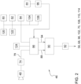
- the Figure 2 shows the electronic control unit 46 and the connected sensors and actuators in detail.
- the electronic control unit 46 comprises a processing unit 86 and a control unit 90.
- a camera 48 is mounted on the front of the roof of the cabin 38 and serves to capture the crop 76 in front of the harvesting machine 10.
- An image processing unit 76 receives the image signals from the camera 74 and sends signals 78 to the processing unit 86.
- the processing unit 86 also receives signals from a position determining device 120, a sensor 122 for detecting the position of the actuator 114, a sensor 80 for detecting the position of the actuator 58, a sensor 82 for detecting the position of the actuator 68, a sensor 84 for detecting the position of the actuator 70, a sensor 104 for detecting the position of the actuator 98 and a sensor 106 for detecting the position of the actuator 102.
- the operator interface 44 is connected via a signal conditioner 96 to the processing unit 86, which is also connected to a memory 124.
- the control unit 90 receives from the signal processing unit 86, on the one hand, signals 88 which contain setpoint values for the working parameters or settings of the actuators 58, 68, 98, 102, 70, 108, 110, 114 and, on the other hand, signals 94 which contain actual values of the working parameters or positions of the actuators 58, 68, 98, 102, 70, 108, 110, 114 and issues corresponding control signals to the actuators 58, 68, 98, 102, 70, 108, 110, 114 (or drivers or valve units or the like connected between the control unit and the actuators 58, 68, 98, 102, 70, 108, 110, 114) in order to transmit the actual values of the working parameters to to adjust the target values.
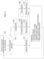
- a first possible mode of operation of the electronic control unit 46 is shown in the Figure 3 shown.
- three data sets are stored in the memory 124 for settings of the actuator 70 for specifying the height of the cutting unit 18 above the ground, the actuator 68 for the position of the reel 52 in the forward direction V, the actuator 58 for the vertical position of the reel 52, the speed of the actuator 110 for specifying the rotational speed of the reel 52 (or the ratio between the reel speed and the forward speed of the harvesting machine 10) and the actuator 114 for the angle of inclination of the reel tines 66.
- the first data set corresponds to normal harvesting operation
- the second data set to stored grain lying in the direction of travel
- the third data set to stored grain lying transversely.
- step 300 the operator monitors the condition of the crop 76 in front of the cutting unit 18. By pressing an associated button on the operator interface 44 (or not pressing a button provided for entering stored grain), he can inform the control unit 46 that there is normal standing grain (step 302). If this is the case, the first data set is called up in step 310 and the actuators 70, 68, 58, 110 and 114 are controlled using the first data set in step 316. If the operator reports via the operator interface 44 that there is stored grain, for which a corresponding button can be pressed, step 304 follows, after which the direction of the stored grain can be entered (steps 306, 308), for which further buttons can be provided on the operator interface 44.
- buttons one of which has a symbol oriented in the forward direction V and one of which has a transverse symbol, e.g. an arrow, the first-mentioned symbol being assigned to step 306 and the second-mentioned symbol to step 308.
- the second data set is called up in step 312 and the actuators 70, 68, 58, 110 and 114 are controlled using the second data set in step 316.
- the third data set is called up in step 314 and the actuators 70, 68, 58, 110 and 114 are controlled using the third data set in step 316. Possible details of these data sets are explained in the discussion of the second embodiment of the procedure of the control unit 46.
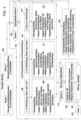
- FIG. 4 a second possible procedure of the electronic control unit 46 is shown.
- This automated procedure uses a first sensor to monitor the crop stock 76 in front of the cutting unit 18 and a second sensor to monitor the material flow in the cutting unit 18.
- the camera 48 with the image processing system 74 takes over the tasks of both sensors.
- the first sensor is used to detect any grain that may be lying in front of the cutting unit 18.
- the image processing system 74 therefore uses the image signals from the camera 48 to detect whether and, if so, in which orientation there is stored grain in front of the cutting unit 18.
- this information can have been obtained in advance, e.g. by means of a drone equipped with a camera that has flown over the field, and stored in a map in the memory 124 and read out based on the position and direction of travel of the harvesting machine 10 determined by the position determination device 120.
- the second sensor serves to monitor the material flow in the cutting unit 18, in particular in the receiving area, ie in the area from the cutter bar 50 to the cross conveyor 112.
- the camera 48 can provide suitable images which are evaluated by the image processing system 74.
- EP 2 143 316 A1 and the DE 10 2016 202 628 A1 which are incorporated by reference into these documents.
- step 400 the processing unit 86 therefore receives the signals 78 from the image processing system, which indicate possible stored grain or disturbances in the material flow in the receiving area of the cutting unit 18.
- Step 400 is followed by step 402, in which it is checked whether the first sensor has detected stored grain. If this is not the case, step 418 follows, in which it is checked whether signals from the second sensor (ie the image processing system 74) indicate to the processing unit 86 that there is a disturbance in the material flow in the receiving area of the cutting unit 18 between the knife bar 50 and the cross conveyor 112. If this is not the case, step 424 follows, in which the processing unit 86 retrieves a series of basic settings for the actuators 70, 68, 58, 110 and 114 from the memory 124. These basic settings can have been entered beforehand by the operator or can be preset at the factory.
- the actuators 70, 68, 58, 110 and 114 are therefore operated with sensible working parameters that are well suited to normal conditions (standing crop 76).
- the reel 52 should only slightly assist the intake of the grain. All settings are such that the reel 52 does not loosen any grains from the ears, or that loosened grains cannot fall to the ground in front of the cutting unit.
- the reel tines 66 should be almost vertical or only slightly set back. The reel 52 only dips into the crop 76 shortly before the knife bar 50. The reel 52 is at a height such that the reel tine carriers 64 can only lightly touch the tips of the ears. When the reel tines 66 dip, the relative movement between the reel tines 66 and the ears should be minimal.
- the horizontal component of the reel speed is only slightly higher than the driving speed, so that the cut grain is only slightly pushed into the cutting unit 18.
- the ratio of reel speed to driving speed is determined using systems for reel speed control that are already in common use. This setting of the four parameters can be saved as a "basic setting" and can be quickly accessed at any time by activating an assigned button on the operator interface 44, analogous to step 310 of the Figure 3 .
- step 404 follows, in which the orientation of the stored grain is determined by the image processing system 74 based on the signals from the first sensor, for which reference is again made to the disclosures of US patent application 62/535043 of July 20, 2017 (published as US 2019/0021226 A1 ) and the DE 10 2016 215 197 A1 is referred to.
- step 408 in which the cutting unit height (actuator 70) is brought to a minimum, i.e. the cutting unit 18 is operated with a floating position of the actuator 70.
- the reel 52 is moved as far forward as possible with the actuator 68, so that the lowest point of the path of the reel tines 66 is located far in front of the knife bar 50.
- the reel 52 is brought into a relatively low position with the actuator 68, which is below the basic position according to step 424.
- the inclination of the reel tines 66 is adjusted far to the rear with the actuator 114, i.e.
- the reel tines 66 extend at the lowest point of their path from the reel tine carrier 64 relatively obliquely backwards and downwards, e.g. at an angle of approx. 45° or up to 60°.
- the speed of the reel 52 is increased by the actuator 110, so that the so-called K factor, which is multiplied by the forward speed of the harvesting machine 10 to determine the speed, is much higher than in the basic setting (step 424).
- K factor which is multiplied by the forward speed of the harvesting machine 10 to determine the speed
- the reel tines 66 should reach under the ears well in front of the knife bar 50, lift the crop 76 (grain) so that it can be cut and then lift it into the cutting unit 18.
- the reel tines 66 are therefore positioned far back, up to 60° for very flat grain. They should be able to slide under the lying ears.
- the reel 52 is positioned far forward so that the reel tine supports 64 reach the lowest point of the track well in front of the knife bar 50 and then come back up again.
- the reel 52 is positioned so low that the reel tines 66 can slide under the ears.
- the speed of the reel 52 is increased significantly so that the crop 76 can be sufficiently lifted before cutting. The minimum speed is such that at least the ears are cut off.
- This setting of the four parameters can be used for step 312 of the Figure 3 can also be saved as a customer-specific setting for stored grain lying in the direction of travel and accessed via an assigned button on the operator interface 44.
- step 412 follows, in which the cutting unit height (actuator 70) is reduced to a minimum, ie the Cutting unit 18 is operated with a floating position of the actuator 70.
- the reel 52 is set in its forward direction to the home position (as in step 424) using the actuator 68.
- the reel 52 is moved to a relatively low position, which is below the home position according to step 424, using the actuator 68.
- the inclination of the reel tines 66 is set to the home position (as in step 424) using the actuator 114.
- the speed of the reel 52 is set to the home position (as in step 424) using the actuator 110.
- ear lifters should be able to move easily under the grain 76 and lift it. Since the cutting table literally slides under the grain 76 until it is cut, it usually slides easily into the cutting unit 18 without additional support.
- the reel tines 66 remain vertical. The horizontal position and the speed remain in the basic setting. If the grain lies across the entire cutting width or at least across most of the cutting width, the reel can be lowered to assist the intake. If it lies across only part of the cutting width, the reel remains at the height of the basic setting, or at the height corresponding to the ear horizon in the standing area.
- step 416 follows in which the cutting unit height (actuator 70) is brought to a minimum, ie the cutting unit 18 is operated with a floating position of the actuator 70.
- the reel 52 is moved forwards with the actuator 68 so that the lowest point of the path of the reel tines 66 is located slightly in front of the cutter bar 50.
- the reel 52 is moved to a relatively low position with the actuator 68, which is below the basic position according to step 424.
- the inclination of the reel tines 66 is adjusted backwards using the actuator 114, ie the reel tines 66 extend backwards and downwards from the reel tine carrier 64 at the lowest point of their path, but less steeply than in step 408.
- the speed of the reel 52 is increased by the actuator 110, so that the so-called K factor, which is multiplied by the forward speed of the harvesting machine 10 to determine the speed, is much higher than in the basic setting (step 424).
- K factor which is multiplied by the forward speed of the harvesting machine 10 to determine the speed
- the reel 52 can help to place the grain 76 on the grain lifters.
- the reel parameters are set as in step 408, with the difference that the reel 52 now engages in the grain just before the grain lifters. If no grain lifters are used, then it only engages just before the knife bar 50.
- This setting of the four parameters can be used for step 314 of the Figure 3 can also be saved as a customer-specific setting for stored grain lying in the direction of travel and accessed via an assigned button on the operator interface 44.
- Steps 402, 408, 412 and 416 are followed by step 418 already mentioned above, in which it is queried whether signals from the second sensor (i.e. the image processing system 74) indicate to the processing unit 86 that there is a disturbance in the material flow in the receiving area of the cutting unit 18 between the knife bar 50 and the cross conveyor 112.
- the second sensor i.e. the image processing system 74
- step 424 follows and otherwise step 420 follows, in which the processing unit 86 instructs the actuator 54 via the control unit 90 to slightly raise the reel 52 (compared to the position after step 408, 410 or 412) or (directly starting from step 402) to lower it compared to the normal position and optionally reduces the speed of the reel 52 by the actuator 110 so that the so-called K factor, which is multiplied by the forward speed of the harvesting machine 10 to determine the speed, is lower than in the basic setting (step 424).
- the reel tines 66 can also be set tilted backwards in order to allow them to engage the jammed material more aggressively. The reel 52 is therefore in a relatively low position until the reel tines 6 briefly brush over the knife bar 50 or over the cutting table. In stubborn cases, the reel speed is also increased.
- step 422 it is checked whether the fault has been eliminated. If this is the case, step 424 follows and otherwise step 426.
- the intervention according to step 420 preferably only takes place for a short time, on the one hand to give the sensor a clear view of the fault and to check the success of the action and on the other hand to reduce the risk that the reel 52 throws over cut grain or even starts to wind itself.
- the sensor should also be able to detect these two cases and at the latest then interrupt an intervention to remove the blockage. The same applies to cases of stored grain, especially if the grain is only lying over a partial width of the cutting unit 18, but is standing in other places.
- the procedure according to step 420 can optionally be repeated one or more times. Only then, if the procedure fails, is a warning issued (step 426) so that the operator can intervene himself.
- the flow charts according to Figure 3 or 4 The actuator settings generated can be overridden in a conventional manner by operator inputs via the operator interface 44 and thus improved if necessary. In addition, they can be fine-tuned by automatic control circuits with closed or open loops.
Landscapes
- Life Sciences & Earth Sciences (AREA)
- Environmental Sciences (AREA)
- Outside Dividers And Delivering Mechanisms For Harvesters (AREA)
- Harvester Elements (AREA)
Description
- Die vorliegende Erfindung bezieht sich auf eine Erntemaschine mit einem Schneidwerk, welches mit einem Messerbalken zum Abschneiden von Erntegut von einem Feld, einer oberhalb des Messerbalkens angeordneten Haspel mit Haspelzinken und einem Querförderer zur Abförderung des abgeschnittenen Ernteguts zu einer rückwärtigen Abgabeöffnung ausgestattet ist, wobei die Haspel um eine Drehachse in Antrieb versetzbare Haspelarme, an den Haspelarmen um ihre Längsachsen drehbar abgestützte Haspelzinkenträger mit daran angebrachten Haspelzinken und einen fremdkraftbetätigten, mit einer elektronischen Steuereinheit verbundenen Aktor zur Verstellung des Drehwinkels der Haspelzinkenträger gegenüber den Haspelarmen umfasst und die elektronische Steuereinheit betreibbar ist, den Aktor abhängig von wenigstens einer Eigenschaft des zu erntenden Ernteguts zu verstellen.
- Schneidwerke dienen in der Landwirtschaft als Erntevorsätze für selbstfahrende Erntemaschinen bei der Getreideernte, in der Regel für Mähdrescher, obwohl sie auch als Erntevorsatz für Feldhäcksler verwendet werden können, beispielsweise bei der Ernte von Ganzpflanzensilage. Schneidwerke umfassen einen Messerbalken, eine darüber angeordnete Haspel und einen Querförderer, der das abgeschnittene Erntegut an einen Schrägförderer des Mähdreschers oder Einzugsförderer des Feldhäckslers abgibt. Die Haspel dient dazu, in den stehenden Bestand des Ernteguts einzugreifen und ihn nach hinten zu fördern, damit es durch den Messerbalken abgeschnitten und vom Querförderer erfasst werden kann. Die Haspel umfasst üblicherweise eine Anzahl an Haspelzinkenträgern, die an Haspelarmen angebracht sind, die ihrerseits um eine mittige, sich in Querrichtung erstreckende Achse in Drehung versetzbar sind. An den Haspelzinkenträgern sind Haspelzinken angebracht. Da die Haspelzinkenträgern gegenüber den Haspelarmen drehbar gelagert sind, ist die Orientierung der Finger über einen Umlauf im Stand der Technik nicht radial zur Drehachse der Haspelarme, sondern im Wesentlichen nach unten orientiert, was durch eine geeignete Steuerung erzielt wird, die beispielsweise unter Verwendung von Nockenbahnen (
US 6 170 244 B1 ) oder Ketten (DE 1 047 516 B ) oder Zahnrädern (WO 2016/101059 A1 ) eine in geeigneter Weise geformte Vorgabeeinrichtung z.B. in Form einer Steuerkurve abtasten kann. - Die Ernte von Druschfrüchten mit hoher Durchsatzleistung und in hoher Qualität beginnt am Schneidwerk. Die Haspel unterstützt die Aufnahme von Getreide und die richtige Anwendung trägt wesentlich zu einem gleichmäßigen Materialfluss und zu geringen Schneidwerksverluste bei. Im umgedrehten Fall können aber bei falscher Einstellung der Parameter hohe Schneidwerksverluste entstehen und durch ungleichmäßigen Materialfluss die Funktion aller nachfolgenden Drusch- und Abscheideorgane negativ beeinträchtigt werden wobei die Effizienz des gesamten Mähdreschers sinkt. Die richtige Anpassung aller verstellbaren Haspelparameter erfordert von dem Maschinenbediener viel Erfahrung.
- Des Weiteren sind durch verbesserte Pflanzenbaumaßnahmen Bestände mit gleichmäßigen Störungen über größere Flächen eher selten (z.B. Lagergetreide), jedoch Felder mit unterschiedlichen Bestandseigenschaften in nebeneinanderliegenden Teilflächen häufiger (z.B. witterungsbedingt oder durch Wild nieder gedrücktes Getreide). Der Bediener müsste dann in kurzer Zeit mehrerer Haspelparameter gleichzeitig einstellen. Auf Grund immer höhere Erntegeschwindigkeiten und immer breiterer Schneidwerke wird das immer schwerer.
- Oftmals sieht man im Feld Streifen mit Lagergetreide. Diese Streifen können durch Überlappung bei der Düngerausbringung verursacht sein. Die partielle Überdüngung kann zu Lagergetreide führen. Solche Lagerstellen, die sich nicht über die gesamte Schneidwerksbreite erstrecken, sind besonders schwer zu handhaben. Die Einstellung des Schneidwerkes kann dann immer nur ein Kompromiss bezüglich dem normal stehenden Getreide und dem liegenden Getreide sein, wobei auch hier eine schnelle Anpassung von mehreren Einstellparametern erforderlich ist.
- Als verstellbare Größen der Haspel sind die Drehzahl, die Höhe und die Vorwärtsposition zu nennen. Im Stand der Technik wurde schon eine selbsttätige Einstellung dieser Größen basierend auf sensierten Erntegutparametern, wie Bestandshöhe, vorgeschlagen (
EP 2 517 549 A1 ,DE 10 2016 118 637 A1 ), oder eine von der Schnitthöhe abhängige Einstellung dieser Größen (EP 0 812 530 A1 ) oder eine Verstellung der Position der Haspel bei Schneidwerksverlusten, die mittels einer Kamera erkannt werden (DE 10 2016 202 628 A1 ). Weiterhin beschreibt dieDE 10 2016 215 197 A1 eine selbsttätige Einstellung eines nicht näher definierten Arbeitsparameters eines Erntevorsatzes im Falle einer sensorischen Erkennung von Lagergetreide. - Eine weitere, verstellbare Größe des Schneidwerks ist die Orientierung der Haspelzinken um die Drehachse der Haspelzinkenträger. Im Stand der Technik wird diese Einstellung durch eine mechanische Verstellung eines an der Haspel angebrachten Hebels durchgeführt (vgl. beispielsweise
DE 1 047 516 B ), um die Orientierung der Haspelzinken an die Erntegutart und -bedingungen anzupassen. Eine Änderung während des Erntevorgangs ist demnach nicht bzw. nur unter hohem zeitlichen Aufwand möglich, auch wenn sich die Bedingungen während der Ernte auf einem Feld ändern sollten. Die als gattungsbildend angeseheneUS 8 800 256 B2 beschreibt eine Haspelanordnung mit einem Haspelzinkenwinkelverstellring, der durch einen Aktor verstellbar ist, um den Winkel der Haspelzinken während des Umlaufs zu verstellen. Die Verstellung erfolgt durch einen Bediener in der Kabine des Mähdreschers oder selbsttätig basierend auf der Vortriebsgeschwindigkeit des Mähdreschers oder der Drehzahl der Haspel oder der Dichte des Ernteguts. Eine ferngesteuerte Verstellung der Orientierung der Haspelzinken wird auch in derEP 1 297 735 A1 erwähnt, jedoch mit der Bemerkung, dass eine Automatisierung der unabhängigen Verstellung der Drehwinkel aller Haspelzinkenträger aufgrund der hohen Komplexität weniger wünschenswert sein dürfte. Schließlich beschreibt dieDE 24 11 153 A1 ein Schneidwerk eines Mähdreschers, bei dem die Höhe der Haspel mittels einer Lichtschranke selbsttätig an der Oberseite des Erntegutbestands geführt wird. Wird die Haspel bei Lagergetreide ganz nach unten geführt, erfolgt durch eine mechanische Zwangskopplung eine selbsttätige Verstellung des Winkels der Haspelzinken nach hinten, um das Erntegut besser aufnehmen zu können. - Im Stand der Technik ist nach alledem vorgesehen, die Orientierung der Haspelzinken nur von Hand zu verändern oder (
US 8 800 256 B2 ) sie allenfalls selbsttätig abhängig vom Durchsatz, der Dichte des Ernteguts oder anderen Feldbedingungen oder von der Vorwärtsgeschwindigkeit des Mähdreschers zu verstellen oder (DE 24 11 153 A1 ) mittels einer mechanischen Kopplung mit der Haspelhöhe bei Lagergetreide zu verstellen. Dadurch wird eine optimale Annahme von Erntegut nicht in allen Fällen erzielt. Es gibt zwar andere Parameter der Haspel, die im Stand der Technik bei Lagergetreide (EP 0 812 530 A1 ) oder Förderproblemen (DE 10 2016 202 628 A1 ) verstellt werden, jedoch wird dabei nicht die Orientierung der Haspelzinken variiert. - Eine Erntemaschine ist mit einem Schneidwerk ausgestattet, welches mit einem Messerbalken zum Abschneiden von Erntegut von einem Feld, einer oberhalb des Messerbalkens angeordneten Haspel mit Haspelzinken und einem Querförderer zur Abförderung des abgeschnittenen Ernteguts zu einer rückwärtigen Abgabeöffnung versehen ist. Die Haspel umfasst um eine Drehachse in Antrieb versetzbare Haspelarme, an den Haspelarmen um ihre Längsachsen drehbar abgestützte Haspelzinkenträger mit daran angebrachten Haspelzinken und einen fremdkraftbetätigten, mit einer elektronischen Steuereinheit verbundenen Aktor zur Verstellung des Drehwinkels der Haspelzinkenträger gegenüber den Haspelarmen. Die elektronische Steuereinheit ist betreibbar, den Aktor abhängig von wenigstens einer Eigenschaft des zu erntenden Ernteguts zu verstellen.
- Die Eigenschaft des zu erntenden Ernteguts betrifft die Orientierung der Halme des Ernteguts, d.h. ob es sich um stehenden oder liegenden Bestand (Lagergetreide) handelt und im zweiten Fall ggf. auch die Richtung, in welcher das Lagergetreide liegt, und/oder eine Störung im Materialfluss des Ernteguts im Annahmebereich des Schneidwerks zwischen dem Messerbalken und dem Querförderer, insbesondere mögliche Förderprobleme am Messerbalken, am Querförderer oder dazwischen oder Wickeln der Haspel.
- Das System ist besonders geeignet für die Aufnahme von Lagergetreide und erreicht die höchste Wirksamkeit in Zusammenhang mit einem optischen Sensor, welcher im Feld bereits vor dem Schneidwerk Stellen mit Lagergetreide und die Ausrichtung des Lagergetreides erkennen kann. Eine weitere Verbesserung ist möglich, wenn dieser oder ein zusätzlicher optischer Sensor auch den Bereich um den Messerbalken bis zur Querförderschnecke auf gleichmäßigen Materialfluss, bzw. auf Verstopfungen überwachen kann. Dieser Sensor soll auch erkennen, ob die Haspel zu wickeln beginnt, bzw. abgeschnittenes Getreide über die Haspel wieder nach vorn geworfen wird.
- Die elektronische Steuereinheit ist mit einem Sensor zur Erkennung vor dem Schneidwerk befindlichen Lagergetreides und von dessen Orientierung und/oder einer abgespeicherten Karte, in der Positionen vor dem Schneidwerk befindlichen Lagergetreides und von dessen Orientierung abgespeichert sind und/oder einem Sensor zur Erkennung von Ungleichmäßigkeiten des Förderverhaltens des Ernteguts im Annahmebereich des Schneidwerks verbunden und betreibbar, den Aktor abhängig von der Karte und/oder den Signalen von mindestens einem der Sensoren anzusteuern.
- Die elektronische Steuereinheit ist demnach betreibbar, den Aktor abhängig von der Anwesenheit und Orientierung von aufzunehmenden Lagergetreide anzusteuern. Alternativ oder zusätzlich besteht die Möglichkeit, die Stauung oder Verstopfung automatisch mit der Haspel zu lösen, falls ein Sensor Ungleichmäßigkeiten im Materialfluss des Ernteguts im Annahmebereich des Schneidwerks, d.h. im Bereich des Messerbalkens oder vor dem Querförderer erkennt.
- Die Steuereinheit kann betreibbar sein, weitere Aktoren zur Verstellung der Schneidwerkshöhe und/oder der Position der Haspel in Vorwärtsrichtung und/oder der Position der Haspel in vertikaler Richtung und/oder der Geschwindigkeit der Drehung der Haspel basierend auf Signalen wenigstens eines Sensors und/oder in der Karte eingetragenen Daten anzusteuern.
- Das Schneidwerk wird in Verbindung mit einer Erntemaschine verwendet, bei der es sich um einen Mähdrescher oder Feldhäcksler handeln kann.
- In den Zeichnungen sind zwei nachfolgend näher beschriebene Ausführungsbeispiele dargestellt, von denen die Ausführungsform nach
Figur 3 nicht unter die Ansprüche fällt. Es zeigen: - Fig. 1
- eine seitliche Ansicht eines selbstfahrenden Mähdreschers mit einem Schneidwerk,
- Fig. 2
- ein Schema der elektronischen Steuereinheit mit den zugehörigen Sensoren und Aktoren,
- Fig. 3
- ein Flussdiagramm einer ersten Vorgehensweise der Steuereinheit und
- Fig. 4
- ein Flussdiagramm einer zweiten Vorgehensweise der Steuereinheit.
- Die
Figur 1 zeigt eine selbstfahrende Erntemaschine 10 in der Art eines Mähdreschers. Sie umfasst ein tragendes Fahrgestell 12, das sich durch antreibbare Vorderräder 12 und durch lenkbare Hinterräder 16 auf dem Boden abstützt und durch die Räder 14, 16 in einer Vorwärtsrichtung V über ein Feld bewegbar ist. Die Räder 14 und optional 16 werden durch Antriebsmittel (nicht gezeigt) in Drehung versetzt, um die Erntemaschine 10 über ein abzuerntendes Feld zu bewegen. Im Folgenden beziehen sich Richtungsangaben, wie vorn oder hinten oder seitlich, auf die Vorwärtsrichtung V der Erntemaschine 10, die in derFigur 1 nach links verläuft. - Am vorderen Bereich der Erntemaschine 10 ist ein Erntevorsatz in Form eines Schneidwerks 18 lösbar angebracht, um während des Erntevorgangs Erntegut 76 in Form von Korn oder anderen, druschfähigen Halmfrüchten vom Feld zu ernten und sie nach oben und hinten durch einen Schrägfördererzusammenbau 20 einem axialen Dreschzusammenbau 22 zuzuführen. Das Gemisch aus Korn und anderem Material, das durch Dreschkörbe oder Trennroste des axialen Dreschzusammenbaus 22 tritt, erreicht eine Reinigungseinrichtung 26. Von der Reinigungseinrichtung 26 gewonnenes, sauberes Korn wird durch eine Körnerschnecke 28 einem Kornelevator 30 zugeführt, der es in einen Korntank 32 fördert. Das saubere Korn im Korntank 32 kann durch ein Entladesystem mit einer Querförderschnecke 34 und einem Entladeschneckenförderer 36 auf ein Transportfahrzeug überladen werden. Die durch die axiale Dreschanordnung 22 ausgestoßenen Erntegutreste werden mittels einer Fördertrommel 40 einem Strohhäcksler 42 zugeführt, der sie häckselt und über die Breite des Schneidwerks über das Feld verteilt. Die erwähnten Systeme werden durch einen Verbrennungsmotor angetrieben und werden durch einen Bediener in einer Kabine 38 kontrolliert. Die gezeigte, axiale Dreschanordnung 22 mit einem oder mehreren axialen Dresch- und Trennrotoren ist lediglich eine beispielhafte Ausführung und kann durch eine tangentiale Dreschanordnung mit einer oder mehreren Dreschtrommeln und nachfolgenden Strohschüttlern oder Trennrotoren ersetzt werden.
- Das Schneidwerk 18 umfasst einen sich hin- und her bewegenden Messerbalken 50, der sich im Wesentlichen über die gesamte Breite des Schneidwerks 18 erstreckt. Der Messerbalken 50 kann, wie im Stand der Technik bekannt, starr oder flexibel sein. Eine Haspel 52 ist am Schneidwerk 18 angebracht und erstreckt sich im Wesentlichen über die gesamte Breite des Schneidwerks 18 (oder einen Teil davon). Die äußeren Enden der Haspel 52 sind an Armen 54 abgestützt, von denen in der
Figur 1 nur einer gezeigt wird. Die Arme 54 haben rückwärtige Enden, die um sich quer zur Vorwärtsrichtung erstreckende Achsen am Rahmen 56 des Schneidwerks, 18, der sich ebenfalls über die Breite des Schneidwerks 18 erstreckt, angelenkt sind und sich von dort nach vorn erstrecken. Jeder Arm 54 ist mit einem Aktor 58 in Form eines hydraulischen Zylinders gekoppelt, der schwenkbar am Rahmen 56 und am Arm 54 angelenkt ist. Die Arme 54 und somit die Haspel 52 werden durch ein Verstellen (Einziehen und Ausstrecken) des Aktors 58 abgesenkt und angehoben. - An einem mittigen Rohr 62, das durch einen kontrollierbaren Antrieb 110 während des Erntebetriebs (in
Figur 1 im Gegenuhrzeigersinn) in Drehung versetzbar ist, sind über sich radial zum Rohr 62 erstreckende Haspelarme 116 Haspelzinkenträger 64 abgestützt, die sich über die Breite des Schneidwerks 18 oder einen Teil davon erstrecken und an denen Haspelzinken 66 angebracht sind. Ein zweiter Aktor 68 in Form eines hydraulischen Zylinders ist angepasst, die horizontale Position der Haspel 52 zu verstellen, indem er eine Stützlagerung des Rohrs 62 entlang des Arms 54 bewegt. Das Schneidwerk 18 umfasst auch einen Querförderer 112, der als Schneckenförderer (wie gezeigt) oder Förderbänder ausgeführt sein kann, um das vom Messerbalken 50 abgeschnittene Erntegut zur Mitte des Schneidwerks 18 zu fördern und es von dort durch eine rückwärtige Öffnung im Rahmen 56 dem Schrägförderer 20 zuzuführen. Die Höhe des Schneidwerks 18 über dem Boden wird durch einen vierten Aktor 70 definiert, welcher den Schrägförderer 20 und somit das lösbar daran befestigte Schneidwerk 18 um eine sich quer zur Vorwärtsrichtung erstreckende, horizontale Achse 72 gegenüber dem Fahrgestell 12 der Erntemaschine 10 verschwenkt. Der Aktor 70 wird durch eine elektronische Steuereinheit 46 basierend auf einer Bedienereingabe über eine Bedienerschnittstelle 44 oder selbsttätig kontrolliert, wobei die elektronische Steuereinheit 46 das Schneidwerk 18 in einer gewünschten Höhe über dem Boden halt oder es mit einem gewünschten Druck über den Boden führt. Wie im Stand der Technik bekannt, kann das Schneidwerk 18 zusätzlich um eine sich horizontal, in Vorwärtsrichtung erstreckende Achse verschwenken, um der Bodenkontur zu folgen, ebenfalls durch die Steuereinheit 46 und einen zugehörigen Aktor kontrolliert. Ein Aktor 98 kann die Neigung des Schneidwerks 18 um die Querachse gegenüber dem Schrägförderer 20 kontrollieren. - Die Länge des Schneidtisches ist durch einen Aktor 102 kontrollierbar. Demnach ist die horizontale Position des Messerbalkens 50 gegenüber dem Rahmen 56 des Schneidwerks 18 durch den Aktor 102 verstellbar, der durch die Bedienerschnittstelle 44 und die elektronische Steuereinheit 46 kontrolliert wird. Mögliche Ausführungsformen eines Schneidwerks 18 mit längenveränderlichem Schneidtisch sind in der
EP 2 803 257 A1 und derWO 03/049532 A1 - Die Haspelzinkenträger64 und somit die Haspelzinken 66 sind gegenüber den Haspelarmen 116 drehbar gelagert, was es ermöglicht, die Haspelzinken 66 über den gesamten Umlauf um das Rohr 62 in einer gewünschten, in der Regel etwa vertikalen Ausrichtung zu halten. Hierzu dienen an sich bekannte Mechanismen (vgl.
DE 1 047 516 B ,WO 2016/101059 A1 ,US 8 800 256 B2 undEP 1 297 735 A1 , deren Offenbarung durch Verweis mit in die vorliegenden Unterlagen aufgenommen wird), um die Drehstellung der Haspelträgerzinken 64 gegenüber den Haspelarmen 116 abhängig von der Drehstellung der Haspelarme 116 um die Drehachse des Rohrs 62 zu kontrollieren. Die genaue Winkelstellung der Haspelzinkenträger 64 ist über einen Hebel 118 veränderbar, der beispielsweise die Position einer Nockenbahn um die Mittelachse des Rohrs 62 verstellt. Es ist ein weiterer Aktor 114 vorgesehen, um den Hebel 118 zu verstellen. Demnach kann der Aktor 114 den Winkel der Haspelzinkenträger 64 um die Haspelarme 116 variieren. - Der im Stand der Technik (s.
DE 1 047 516 B ) verwendete Hebelmechanismus zur manuellen Einstellung der Neigung der Haspelzinken 66 wird demnach an einem oder beiden Enden der Haspel 52 durch einen Aktor 114 ersetzt. Dieser kann elektrisch, hydraulisch oder pneumatisch sein. Eine Positionsmessung (Sensor 122) hilft, die tatsächliche Neigung zu bestimmen oder die Wunschneigung schnell anfahren zu können. Die Positionsmessung kann genutzt werden, um beide Seiten synchron verstellen zu können, oder aber auch, um die Neigung über die Breite gezielt versetzt vornehmen zu können. Dabei wird die material- und strukturbedingte Flexibilität der Haspel 52 ausgenutzt. Sollte sich die Haspel 52 aus mehreren, seitlich nebeneinander angeordneten Haspeln 52 zusammensetzen, kann jede Haspel 52 mit einem oder zwei Aktor(en) 114 ausgestattet werden, die untereinander unterschiedlich angesteuert werden können, falls über die Schneidwerksbreite unterschiedliche Erntegutbedingungen vorliegen sollten. - Die Steuereinheit 46 kann zudem einen Aktor 108 zur Vorgabe der Vortriebsgeschwindigkeit der Erntemaschine 10 kontrollieren.
- Die
Figur 2 zeigt die elektronische Steuereinheit 46 und die angeschlossenen Sensoren und Aktoren im Detail. Die elektronische Steuereinheit 46 umfasst eine Verarbeitungseinheit 86 und eine Kontrolleinheit 90. - Eine Kamera 48 ist an der Vorderseite des Daches der Kabine 38 angebracht und dient dazu, das Erntegut 76 vor der Erntemaschine 10 zu erfassen. Eine Bildverarbeitung 76 erhält die Bildsignale der Kamera 74 und gibt Signale 78 an die Verarbeitungseinheit 86.
- Die Verarbeitungseinheit 86 erhält auch Signale von einer Positionsbestimmungseinrichtung 120, einem Sensor 122 zur Erfassung der Position des Aktors 114, einem Sensor 80 zur Erfassung der Position des Aktors 58, einem Sensor 82 zur Erfassung der Position des Aktors 68, einem Sensor 84 zur Erfassung der Position des Aktors 70, einem Sensor 104 zur Erfassung der Position des Aktors 98 und einem Sensor 106 zur Erfassung der Position des Aktors 102. Die Bedienerschnittstelle 44 ist über einen Signalformer 96 mit der Verarbeitungseinheit 86 verbunden, welche zudem mit einem Speicher 124 verbunden ist. Die Kontrolleinheit 90 erhält von der Signalverarbeitungseinheit 86 einerseits Signale 88, die Sollwerte für die Arbeitsparameter bzw. Einstellungen der Aktoren 58, 68, 98, 102, 70, 108, 110, 114 beinhalten und andererseits Signale 94, die Istwerte der Arbeitsparameter bzw. Positionen der Aktoren 58, 68, 98, 102, 70, 108, 110, 114 beinhalten und gibt entsprechende Kontrollsignale an die Aktoren 58, 68, 98, 102, 70, 108, 110, 114 (bzw. zwischen die Kontrolleinheit und die Aktoren 58, 68, 98, 102, 70, 108, 110, 114 geschaltete Treiber oder Ventileinheiten o. dgl.) ab, um die Istwerte der Arbeitsparameter an die Sollwerte anzupassen.
- Es wäre auch möglich, auf einen oder mehreren der Sensoren 122, 80, 82, 84, 104 und 106 zu verzichten oder deren Signale zu ergänzen, indem man die Signale der Kamera 48 mit dem Bildverarbeitungssystem 74 auswertet, um die aktuellen Betriebsparameter eines oder mehrerer der Aktoren 58, 68, 98, 102, 70, 108, 114 bzw. die derzeitigen Positionen der vom betreffenden Aktor verstellten Elemente zu bestimmen. Hierzu wird auf die
indische Patentanmeldung 201821013464 - Eine erste, mögliche Arbeitsweise der elektronischen Steuereinheit 46 ist in der
Figur 3 dargestellt. Hierbei sind im Speicher 124 drei Datensätze für Einstellungen des Aktors 70 zur Vorgabe der Höhe des Schneidwerks 18 über dem Boden, des Aktors 68 für die Position der Haspel 52 in Vorwärtsrichtung V, des Aktors 58 für die vertikale Position der Haspel 52, die Drehzahl des Aktors 110 zur Vorgabe der Drehgeschwindigkeit der Haspel 52 (bzw. des Verhältnisses zwischen Haspeldrehzahl und Vorwärtsgeschwindigkeit der Erntemaschine 10) und des Aktors 114 für den Neigungswinkel der Haspelzinken 66 abgespeichert. Der erste Datensatz entspricht dem normalen Erntebetrieb, der zweite Datensatz in Fahrtrichtung liegendem Lagergetreide und der dritte Datensatz in Querrichtung liegendem Lagergetreide. - Im Schritt 300 überwacht der Bediener den Zustand des Ernteguts 76 vor dem Schneidwerk 18. Durch Betätigen einer zugeordneten Taste an der Bedienerschnittstelle 44 (oder Nicht-Betätigen einer zur Eingabe von Lagergetreide vorgesehenen Taste) kann er der Steuereinheit 46 mitteilen, dass normal stehendes Getreide vorliegt (Schritt 302). Ist das der Fall, wird im Schritt 310 der erste Datensatz abgerufen und im Schritt 316 die Aktoren 70, 68, 58, 110 und 114 anhand des ersten Datensatzes angesteuert. Teilt der Bediener über die Bedienerschnittstelle 44 mit, das Lagergetreide vorliegt, wozu eine entsprechende Taste betätigt werden kann, folgt der Schritt 304, auf den eine Eingabe der Richtung des Lagergetreides durchgeführt werden kann (Schritte 306, 308), wozu weitere Tasten an der Bedienerschnittstelle 44 vorgesehen sein können. Es besteht auch die Möglichkeit, mittels eines kleinen Joysticks an der Bedienerschnittstelle 44 die Eingaben der Schritte 302 bis 308 durchzuführen. Wenn der Joystick in der Ruheposition ist, entspricht das einer Eingabe stehenden Ernteguts 76, während ein nach vorn oder hinten verstellter Joystick in Vorwärtsrichtung V liegendes Lagergetreide und ein zur Seite verstellter Joystick quer zur Vorwärtsrichtung V liegendes Lagergetreide repräsentiert. Analog kann die Bedienerschnittstelle 44 mit Tasten ausgerüstet sein, von denen eine ein in Vorwärtsrichtung V orientiertes Symbol und eine ein quer gerichtetes Symbol, z.B. einen Pfeil, aufweist, wobei das erstgenannte Symbol dem Schritt 306 und das zweitgenannte Symbol dem Schritt 308 zugeordnet ist. Bei in Fahrtrichtung liegendem Lagergetreide wird im Schritt 312 der zweite Datensatz abgerufen und im Schritt 316 die Aktoren 70, 68, 58, 110 und 114 anhand des zweiten Datensatzes angesteuert. Bei quer zur Fahrtrichtung liegendem Lagergetreide wird im Schritt 314 der dritte Datensatz abgerufen und im Schritt 316 die Aktoren 70, 68, 58, 110 und 114 anhand des dritten Datensatzes angesteuert. Mögliche Einzelheiten zu diesen Datensätzen werden in der Diskussion zur zweiten Ausführungsform der Vorgehensweise der Steuereinheit 46 erläutert.
- In der
Figur 4 wird eine zweite, mögliche Vorgehensweise der elektronischen Steuereinheit 46 dargestellt. Diese automatisierte Vorgehensweise nutzt einen ersten Sensor zur Überwachung des Bestandes des Ernteguts 76 vor dem Schneidwerk 18 und einen zweiten Sensor zur Überwachung des Materialflusses im Schneidwerk 18. Vorzugsweise übernimmt die Kamera 48 mit dem Bildverarbeitungssystem 74 die Aufgaben beider Sensoren. - Der erste Sensor dient dazu, eventuell vor dem Schneidwerk 18 liegendes Lagergetreide zu erkennen. Hierzu wird auf die Offenbarungen der
US-Patentanmeldung 62/535043 vom 20. Juli 2017 US 2019/0021226 A1 ) und derDE 10 2016 215 197 A1 verwiesen, die durch Verweis mit in die vorliegenden Unterlagen aufgenommen werden. Das Bildverarbeitungssystem 74 erkennt demnach anhand der Bildsignale der Kamera 48, ob und ggf. in welcher Orientierung Lagergetreide vor dem Schneidwerk 18 liegt. Diese Information kann alternativ oder zusätzlich schon vorab gewonnen worden sein, z.B. mittels einer mit einer Kamera bestückten Drohne, die über das Feld geflogen ist, und in einer Karte im Speicher 124 abgelegt sein und anhand der mit der Positionsbestimmungseinrichtung 120 bestimmten Position und Fahrtrichtung der Erntemaschine 10 ausgelesen werden. - Der zweite Sensor dient dazu, den Materialfluss im Schneidwerk 18 zu überwachen, insbesondere im Annahmebereich, d.h. im Bereich vom Messerbalken 50 bis zum Querförderer 112. Auch hier kann die Kamera 48 geeignete Bilder liefern, die vom Bildverarbeitungssystem 74 ausgewertet werden. Hierzu sei auf die Offenbarungen der
EP 2 143 316 A1 und derDE 10 2016 202 628 A1 verwiesen, die durch Verweis mit in die vorliegenden Unterlagen aufgenommen werden. - Im Schritt 400 erhält die Verarbeitungseinheit 86 demnach die Signale 78 vom Bildverarbeitungssystem, die auf eventuelles Lagergetreide oder Störungen im Materialfluss im Annahmebereich des Schneidwerks 18 hinweisen.
- Auf den Schritt 400 folgt der Schritt 402, in dem abgefragt wird, ob der erste Sensor Lagergetreide erkannt hat. Ist das nicht der Fall, folgt der Schritt 418, in dem abgefragt wird, ob der Verarbeitungseinheit 86 Signale vom zweiten Sensor (d.h. dem Bildverarbeitungssystem 74) darauf hinweisen, dass eine Störung im Materialfluss im Annahmebereich des Schneidwerks 18 zwischen Messerbalken 50 und Querförderer 112 vorliegt. Ist das nicht der Fall, folgt der Schritt 424, in dem die Verarbeitungseinheit 86 eine Reihe an Grundeinstellungen für die Aktoren 70, 68, 58, 110 und 114 aus dem Speicher 124 abruft. Diese Grundeinstellungen können zuvor durch den Bediener eingegeben worden sein oder werksseitig fest vorgegeben werden. Die Aktoren 70, 68, 58, 110 und 114 werden demnach mit sinnvollen Arbeitsparametern betrieben, die in üblichen Bedingungen (stehendes Erntegut 76) gut geeignet sind. Die Haspel 52 soll den Einzug des Getreides nur leicht unterstützen. Alle Einstellungen sind so, dass durch die Haspel 52 keine Körner aus den Ähren gelöst werden, bzw. gelöste Körner nicht vor dem Schneidwerk auf den Boden fallen können. Die Haspelzinken 66 sollten nahezu senkrecht oder nur ganz leicht nach hinten gestellt stehen. Die Haspel 52 taucht erst kurz vor dem Messerbalken 50 in den Bestand 76 ein. Die Haspel 52 steht in einer Höhe, sodass die Haspelzinkenträger 64 die Spitzen der Ähren nur leicht berühren können. Beim Eintauchen der Haspelzinken 66 soll die Relativbewegung zwischen Haspelzinken 66 und Ähren nur minimal sein. Die horizontale Komponente der Haspelgeschwindigkeit ist nur etwas höher als die Fahrgeschwindigkeit, sodass das abgeschnittene Getreide nur leicht in das Schneidwerk 18 hineingeschoben wird. Das Verhältnis Haspeldrehzahl / Fahrgeschwindigkeit wird mit bereits allgemein üblichen Systemen zur Haspeldrehzahlregelung festgelegt. Diese Einstellung der vier Parameter kann als "Grundeinstellung" gespeichert und durch Aktivierung einer zugeordneten Taste der Bedienerschnittstelle 44 jederzeit schnell angesteuert werden, analog zu Schritt 310 der
Figur 3 . - Ergibt sich in Schritt 402 hingegen, dass der erste Sensor Lagergetreide erkennt, folgt der Schritt 404, in dem die Ausrichtung des Lagergetreides anhand der Signale des ersten Sensors durch das Bildverarbeitungssystem 74 bestimmt wird, wozu wieder auf die Offenbarungen der
US-Patentanmeldung 62/535043 vom 20. Juli 2017 US 2019/0021226 A1 ) und derDE 10 2016 215 197 A1 verwiesen wird. - Liegt das Lagergetreide in Fahrtrichtung mit den Ähren nach vorn (Schritt 406), folgt der Schritt 408, in dem die Schneidwerkshöhe (Aktor 70) auf ein Minimum gebracht wird, d.h. das Schneidwerk 18 wird mit einer Schwimmstellung des Aktors 70 betrieben. Die Haspel 52 wird mit dem Aktor 68 möglichst weit nach vorn verschoben, sodass sich der tiefste Punkt der Bahn der Haspelzinken 66 weit vor dem Messerbalken 50 befindet. Die Haspel 52 wird mit dem Aktor 68 in eine relativ niedrige Position verbracht, die unterhalb der Grundposition gemäß Schritt 424 liegt. Die Neigung der Haspelzinken 66 wird mit dem Aktor 114 weit nach hinten verstellt, d.h. die Haspelzinken 66 erstrecken sich auf dem tiefsten Punkt ihrer Bahn vom Haspelzinkenträger 64 relativ schräg nach hinten und unten, z.B. unter einem Winkel von ca. 45° oder bis zu 60°. Zudem wird die Drehzahl der Haspel 52 durch den Aktor 110 erhöht, sodass der so genannte K-Faktor, der zur Bestimmung der Drehzahl mit der Vorwärtsgeschwindigkeit der Erntemaschine 10 multipliziert wird, weit höher als in der Grundeinstellung (Schritt 424) liegt. Diese Einstellungen eignen sich besonders gut zur Aufnahme von Lagergetreide, dessen Ähren vom Schneidwerk 18 weg nach vorn zeigen, insbesondere innerhalb eines Winkelbereichs von +/- 60° gegenüber der Vorwärtsrichtung V.
- Bei derartigen Bedingungen sind Ährenheber in der Regel wirkungslos. Die Haspelzinken 66 sollen weit vor dem Messerbalken 50 unter die Ähren greifen, das Erntegut 76 (Getreide) anheben, so dass es geschnitten werden kann und dann in das Schneidwerk 18 heben. Die Haspelzinken 66 werden daher weit nach hinten gestellt, bei sehr flach liegendem Getreide bis zu 60°. Sie sollen sich unter die liegenden Ähren schieben können. Die Haspel 52 wird weit nach vorn gestellt, sodass die Haspelzinkenträger 64 bereits weit vor dem Messerbalken 50 den tiefsten Bahnpunkt erreichen und anschließend wieder nach oben kommen. Die Haspel 52 ist so tief gestellt, dass sich die Haspelzinken 66 unter die Ähren schieben können. Die Drehzahl der Haspel 52 wird deutlich erhöht, damit das Erntegut 76 vor dem Schnitt ausreichend angehoben werden kann. Die minimale Drehzahl ist so, dass mindestens die Ähren abgeschnitten werden. Mit weiter steigender Haspeldrehzahl kann auch das Stroh tiefer abgeschnitten werden. Die Ausnutzung dieses Spielraumes ist nützlich, wenn weniger nasses Stroh in die Maschine kommen soll (es besteht ein hohes Risiko, dass liegendes Stroh nässer ist) oder Lagergetreide nur auf einen Teil über der Schnittbreite vorhanden ist (das Risiko, dass die Haspel in dem Bereich mit stehenden Getreide wickelt, steigt mit zunehmender Drehzahl). Diese Einstellung der vier Parameter kann für den Schritt 312 der
Figur 3 ebenfalls als kundenspezifische Einstellung für in Fahrtrichtung liegendes Lagergetreide gespeichert und über eine zugeordnete Taste der Bedienerschnittstelle 44 angefahren werden. - Liegt das Lagergetreide in Fahrtrichtung mit den Ähren nach hinten (Schritt 410), folgt der Schritt 412, in dem die Schneidwerkshöhe (Aktor 70) auf ein Minimum gebracht wird, d.h. das Schneidwerk 18 wird mit einer Schwimmstellung des Aktors 70 betrieben. Die Haspel 52 wird mit dem Aktor 68 in ihrer Vorwärtsrichtung in die Grundposition (wie im Schritt 424) gestellt. Die Haspel 52 wird mit dem Aktor 68 in eine relativ niedrige Position verbracht, die unterhalb der Grundposition gemäß Schritt 424 liegt. Die Neigung der Haspelzinken 66 wird mit dem Aktor 114 in die Grundposition (wie im Schritt 424) gestellt. Zudem wird die Drehzahl der Haspel 52 durch den Aktor 110 in die Grundposition (wie im Schritt 424) gestellt. Diese Einstellungen eignen sich besonders gut zur Aufnahme von Lagergetreide, dessen Ähren zum Schneidwerk 18 hin zeigen, insbesondere innerhalb eines Winkelbereichs von +/-60° gegenüber der Vorwärtsrichtung V.
- In diesem Fall sollten Ährenheber gut unter das Getreide 76 fahren und es anheben können. Da sich bis zum Abschneiden der Schneidwerkstisch förmlich unter das Getreide 76 schiebt rutscht es in der Regel auch ohne zusätzliche Unterstützung leicht in das Schneidwerk 18. Die Haspelzinken 66 bleiben senkrecht gestellt. Die Horizontalposition und die Drehzahl bleichen in der Grundeinstellung. Liegt das Getreide über die gesamte Schnittbreite oder zumindest über den größten Teil der Schnittbreite kann die Haspel gesenkt werden, um den Einzug zu unterstützen. Liegt es nur auf einem Teil über die Schnittbreite bleibt die Haspel in Höhe der Grundeinstellung, bzw. in Höhe entsprechend des Ährenhorizonts im stehenden Bereich. Es besteht auch die Möglichkeit, die Einstellungen nach Schritt 412 für eine Einstellung der
Figur 3 für den Fall in Fahrtrichtung liegenden, mit den Ähren nach hinten orientierten Ernteguts 76 als kundenspezifische Einstellung zu speichern und über eine zugeordnete Taste der Bedienerschnittstelle 44 anzufahren. - Liegt das Lagergetreide quer zur Fahrtrichtung (Schritt 414), folgt der Schritt 416, in dem die Schneidwerkshöhe (Aktor 70) auf ein Minimum gebracht wird, d.h. das Schneidwerk 18 wird mit einer Schwimmstellung des Aktors 70 betrieben. Die Haspel 52 wird mit dem Aktor 68 nach vorn verschoben, sodass sich der tiefste Punkt der Bahn der Haspelzinken 66 geringfügig vor dem Messerbalken 50 befindet. Die Haspel 52 wird mit dem Aktor 68 in eine relativ niedrige Position verbracht, die unterhalb der Grundposition gemäß Schritt 424 liegt. Die Neigung der Haspelzinken 66 wird mit dem Aktor 114 nach hinten verstellt, d.h. die Haspelzinken 66 erstrecken sich auf dem tiefsten Punkt ihrer Bahn vom Haspelzinkenträger 64 nach hinten und unten, aber weniger steil als im Schritt 408. Zudem wird die Drehzahl der Haspel 52 durch den Aktor 110 erhöht, sodass der so genannte K-Faktor, der zur Bestimmung der Drehzahl mit der Vorwärtsgeschwindigkeit der Erntemaschine 10 multipliziert wird, weit höher als in der Grundeinstellung (Schritt 424) liegt. Diese Einstellungen eignen sich besonders gut zur Aufnahme von quer vor dem Schneidwerk 18 liegenden Lagergetreide.
- Auch in diesem Fall ist nicht sicher, ob Ährenheber immer ausreichend unter das Lagergetreide gelangen oder ob sie über einen Teil des liegenden Getreides gleiten und diesen Anteil sogar nach unten drücken. Die Haspel 52 kann helfen, das Getreide 76 auf die Ährenheber zu legen. Die Einstellung der Haspelparameter erfolgt wie im Schritt 408, mit dem Unterschied, dass die Haspel 52 jetzt kurz vor den Ährenheber in das Getreide eingreift. Werden keine Ährenheber verwendet dann erst kurz vor dem Messerbalken 50. Diese Einstellung der vier Parameter kann für den Schritt 314 der
Figur 3 ebenfalls als kundenspezifische Einstellung für in Fahrtrichtung liegendes Lagergetreide gespeichert und über eine zugeordnete Taste der Bedienerschnittstelle 44 angefahren werden. - In Zwischenstellungen des Lagergetreides, die zwischen den Winkeln nach Schritt 414 einerseits und 406 oder 410 andererseits liegen, besteht die Möglichkeit, dass die Verarbeitungseinheit 86 Zwischenwerte der Schritte 416 einerseits und 408 oder 412 andererseits verwendet.
- Auf die Schritte 402, 408, 412 und 416 folgt der bereits oben erwähnte Schritt 418, in dem abgefragt wird, ob der Verarbeitungseinheit 86 Signale vom zweiten Sensor (d.h. dem Bildverarbeitungssystem 74) darauf hinweisen, dass eine Störung im Materialfluss im Annahmebereich des Schneidwerks 18 zwischen Messerbalken 50 und Querförderer 112 vorliegt. Ist das nicht der Fall, folgt der Schritt 424 und anderenfalls der Schritt 420, in dem die Verarbeitungseinheit 86 über die Kontrolleinheit 90 den Aktor 54 anweist, die Haspel 52 (gegenüber der Position nach Schritt 408, 410 oder 412) etwas anzuheben bzw. (direkt ausgehend vom Schritt 402) gegenüber der Normalposition abzusenken und optional die Drehzahl der Haspel 52 durch den Aktor 110 vermindert, sodass der so genannte K-Faktor, der zur Bestimmung der Drehzahl mit der Vorwärtsgeschwindigkeit der Erntemaschine 10 multipliziert wird, niedriger als in der Grundeinstellung (Schritt 424) liegt. Auch können die Haspelzinken 66 nach hinten geneigt eingestellt werden, um sie aggressiver in das gestaute Material eingreifen zu lassen. Die Haspel 52 befindet sich demnach in einer relativ niedrigen Position, bis die Haspelzinken 6 kurz über dem Messerbalken 50 oder über den Schneidtisch streifen. In hartnäckigen Fällen wird zusätzlich die Haspeldrehzahl erhöht.
- Im nachfolgenden Schritt 422 wird abgefragt, ob die Störung beseitigt wurde. Ist das der Fall, folgt der Schritt 424 und anderenfalls der Schritt 426. Der Eingriff nach Schritt 420 erfolgt vorzugsweise nur kurzzeitig, einerseits um dem Sensor wieder freie Sicht auf die Störung zu gewähren und den Erfolg der Aktion zu prüfen und andererseits, um das Risiko zu reduzieren, dass die Haspel 52 geschnittenes Getreide überwirft oder gar selbst zu wickeln beginnt. Diese beiden Fälle soll der Sensor ebenfalls erkennen können und spätestens dann einen Eingriff zur Beseitigung der Verstopfung unterbrechen. Das gleiche gilt für Fälle von Lagergetreide, speziell wenn das Getreide nur über eine Teilbreite des Schneidwerks 18 liegt, aber an anderen Stellen steht. Ist die Verstopfung noch nicht beim ersten Mal gelöst, kann die Prozedur nach Schritt 420 optional noch ein- oder mehrere Male wiederholt werden. Erst danach erfolgt nach Misserfolg eine Warnung (Schritt 426), so dass der Bediener selbst eingreifen kann.
- Es besteht die Möglichkeit, bei der Vorgehensweise nach
Figur 3 an der Bedienerschnittstelle 44 eine Eingabemöglichkeit bereitzustellen, mit welcher der Bediener die Einstellungen nach Schritt 420 abrufen kann, um eine Störung zu beseitigen. - Die von den Flussdiagrammen nach
Figur 3 oder4 erzeugten Einstellungen der Aktoren können in an sich bekannter Weise durch Bedienereingaben mittels der Bedienerschnittstelle 44 übersteuert und somit bei Bedarf verbessert werden. Zudem können sie durch automatische Kontrollkreise mit geschlossenen oder offenen Schleifen noch feinabgestimmt werden.
Claims (2)
- Erntemaschine (10) mit einem Schneidwerk (18), welches mit einem Messerbalken (50) zum Abschneiden von Erntegut (76) von einem Feld, einer oberhalb des Messerbalkens (50) angeordneten Haspel (52) mit Haspelzinken (66) und einem Querförderer (112) zur Abförderung des abgeschnittenen Ernteguts zu einer rückwärtigen Abgabeöffnung ausgestattet ist,wobei die Haspel (52) um eine Drehachse in Antrieb versetzbare Haspelarme (116), an den Haspelarmen (116) um ihre Längsachsen drehbar abgestützte Haspelzinkenträger (64) mit daran angebrachten Haspelzinken (66) und einen fremdkraftbetätigten, mit einer elektronischen Steuereinheit (46) verbundenen Aktor (114) zur Verstellung des Drehwinkels der Haspelzinkenträger (64) gegenüber den Haspelarmen (116) umfasstund die elektronische Steuereinheit (46) betreibbar ist, den Aktor (114) abhängig von wenigstens einer Eigenschaft des zu erntenden Ernteguts zu verstellen,dadurch gekennzeichnet, dass die elektronische Steuereinheit (46) mit einem Sensor zur Erkennung vor dem Schneidwerk befindlichen Lagergetreides und von dessen Orientierung und/oder einer abgespeicherten Karte verbunden ist, in der Positionen vor dem Schneidwerk (18) befindlichen Lagergetreides und von dessen Orientierung abgespeichert sind und betreibbar ist, den Aktor (114) abhängig von der Karte und/oder den Signalen des Sensors abhängig von der Anwesenheit und Orientierung von aufzunehmenden Lagergetreide anzusteuern,und/oder dass die elektronische Steuereinheit (46) mit einem Sensor zur Erkennung von Ungleichmäßigkeiten des Förderverhaltens des Ernteguts im Annahmebereich des Schneidwerks (18) zwischen dem Messerbalken (50) und dem Querförderer (112) verbunden ist und betreibbar ist, den Aktor (114) abhängig den Signalen des Sensors anzusteuern.
- Erntemaschine (10) nach Anspruch 1, wobei die Steuereinheit (46) betreibbar ist, weitere Aktoren (70, 68, 58, 110) zur Verstellung der Schneidwerkshöhe und/oder der Position der Haspel (52) in Vorwärtsrichtung und/oder der Position der Haspel (52) in vertikaler Richtung und/oder der Geschwindigkeit der Drehung der Haspel (52) basierend auf Signalen wenigstens eines Sensors und/oder in der Karte eingetragenen Daten anzusteuern.
Applications Claiming Priority (1)
| Application Number | Priority Date | Filing Date | Title |
|---|---|---|---|
| DE102018206507.1A DE102018206507A1 (de) | 2018-04-26 | 2018-04-26 | Schneidwerk mit selbsttätiger Einstellung der Haspelzinkenorientierung |
Publications (2)
| Publication Number | Publication Date |
|---|---|
| EP3560314A1 EP3560314A1 (de) | 2019-10-30 |
| EP3560314B1 true EP3560314B1 (de) | 2024-10-30 |
Family
ID=66217804
Family Applications (1)
| Application Number | Title | Priority Date | Filing Date |
|---|---|---|---|
| EP19169583.2A Active EP3560314B1 (de) | 2018-04-26 | 2019-04-16 | Schneidwerk mit selbsttätiger einstellung der haspelzinkenorientierung |
Country Status (3)
| Country | Link |
|---|---|
| US (1) | US11044847B2 (de) |
| EP (1) | EP3560314B1 (de) |
| DE (1) | DE102018206507A1 (de) |
Families Citing this family (73)
| Publication number | Priority date | Publication date | Assignee | Title |
|---|---|---|---|---|
| US12010950B2 (en) * | 2017-09-15 | 2024-06-18 | Cnh Industrial America Llc | Cam track adjustment assembly for a harvesting reel |
| US11744180B2 (en) * | 2018-01-29 | 2023-09-05 | Deere & Company | Harvester crop mapping |
| US10827676B2 (en) | 2018-01-29 | 2020-11-10 | Deere & Company | Monitor and control system for a harvester |
| DE102019214486B4 (de) | 2018-09-27 | 2023-07-27 | Deere & Company | Erntevorsatzüberwachung anhand von Erntemengenabweichungen |
| US11957072B2 (en) | 2020-02-06 | 2024-04-16 | Deere & Company | Pre-emergence weed detection and mitigation system |
| US11467605B2 (en) | 2019-04-10 | 2022-10-11 | Deere & Company | Zonal machine control |
| US11178818B2 (en) | 2018-10-26 | 2021-11-23 | Deere & Company | Harvesting machine control system with fill level processing based on yield data |
| US11672203B2 (en) | 2018-10-26 | 2023-06-13 | Deere & Company | Predictive map generation and control |
| US11240961B2 (en) | 2018-10-26 | 2022-02-08 | Deere & Company | Controlling a harvesting machine based on a geo-spatial representation indicating where the harvesting machine is likely to reach capacity |
| US11589509B2 (en) | 2018-10-26 | 2023-02-28 | Deere & Company | Predictive machine characteristic map generation and control system |
| US11079725B2 (en) | 2019-04-10 | 2021-08-03 | Deere & Company | Machine control using real-time model |
| US12069978B2 (en) | 2018-10-26 | 2024-08-27 | Deere & Company | Predictive environmental characteristic map generation and control system |
| US11653588B2 (en) | 2018-10-26 | 2023-05-23 | Deere & Company | Yield map generation and control system |
| US11641800B2 (en) | 2020-02-06 | 2023-05-09 | Deere & Company | Agricultural harvesting machine with pre-emergence weed detection and mitigation system |
| DE102018220337A1 (de) | 2018-11-27 | 2020-05-28 | Deere & Company | Erntevorsatz mit verstellbarer Querförderschnecke |
| US11778945B2 (en) | 2019-04-10 | 2023-10-10 | Deere & Company | Machine control using real-time model |
| US11234366B2 (en) | 2019-04-10 | 2022-02-01 | Deere & Company | Image selection for machine control |
| US11793111B2 (en) * | 2019-11-27 | 2023-10-24 | Cnh Industrial America Llc | Harvesting head reel-mounted laser measurement |
| US12329148B2 (en) | 2020-02-06 | 2025-06-17 | Deere & Company | Predictive weed map and material application machine control |
| US12035648B2 (en) | 2020-02-06 | 2024-07-16 | Deere & Company | Predictive weed map generation and control system |
| US12225846B2 (en) | 2020-02-06 | 2025-02-18 | Deere & Company | Machine control using a predictive map |
| US11477940B2 (en) | 2020-03-26 | 2022-10-25 | Deere & Company | Mobile work machine control based on zone parameter modification |
| BR112022023976A2 (pt) * | 2020-05-29 | 2022-12-20 | Cnh Ind America Llc | Controle de altura de coletor para colheitadeira |
| US11635765B2 (en) | 2020-10-09 | 2023-04-25 | Deere & Company | Crop state map generation and control system |
| US11845449B2 (en) | 2020-10-09 | 2023-12-19 | Deere & Company | Map generation and control system |
| US11711995B2 (en) | 2020-10-09 | 2023-08-01 | Deere & Company | Machine control using a predictive map |
| US12419220B2 (en) | 2020-10-09 | 2025-09-23 | Deere & Company | Predictive map generation and control system |
| US11727680B2 (en) | 2020-10-09 | 2023-08-15 | Deere & Company | Predictive map generation based on seeding characteristics and control |
| US11849672B2 (en) | 2020-10-09 | 2023-12-26 | Deere & Company | Machine control using a predictive map |
| US12422847B2 (en) | 2020-10-09 | 2025-09-23 | Deere & Company | Predictive agricultural model and map generation |
| US11675354B2 (en) | 2020-10-09 | 2023-06-13 | Deere & Company | Machine control using a predictive map |
| US11474523B2 (en) | 2020-10-09 | 2022-10-18 | Deere & Company | Machine control using a predictive speed map |
| US11864483B2 (en) | 2020-10-09 | 2024-01-09 | Deere & Company | Predictive map generation and control system |
| US12069986B2 (en) | 2020-10-09 | 2024-08-27 | Deere & Company | Map generation and control system |
| US20220110258A1 (en) | 2020-10-09 | 2022-04-14 | Deere & Company | Map generation and control system |
| US11889788B2 (en) | 2020-10-09 | 2024-02-06 | Deere & Company | Predictive biomass map generation and control |
| US11983009B2 (en) | 2020-10-09 | 2024-05-14 | Deere & Company | Map generation and control system |
| US11946747B2 (en) | 2020-10-09 | 2024-04-02 | Deere & Company | Crop constituent map generation and control system |
| US11825768B2 (en) | 2020-10-09 | 2023-11-28 | Deere & Company | Machine control using a predictive map |
| US11650587B2 (en) | 2020-10-09 | 2023-05-16 | Deere & Company | Predictive power map generation and control system |
| US11849671B2 (en) | 2020-10-09 | 2023-12-26 | Deere & Company | Crop state map generation and control system |
| US11895948B2 (en) | 2020-10-09 | 2024-02-13 | Deere & Company | Predictive map generation and control based on soil properties |
| US12386354B2 (en) | 2020-10-09 | 2025-08-12 | Deere & Company | Predictive power map generation and control system |
| US12013245B2 (en) | 2020-10-09 | 2024-06-18 | Deere & Company | Predictive map generation and control system |
| US11871697B2 (en) | 2020-10-09 | 2024-01-16 | Deere & Company | Crop moisture map generation and control system |
| US12178158B2 (en) | 2020-10-09 | 2024-12-31 | Deere & Company | Predictive map generation and control system for an agricultural work machine |
| US20220110238A1 (en) | 2020-10-09 | 2022-04-14 | Deere & Company | Machine control using a predictive map |
| US11927459B2 (en) | 2020-10-09 | 2024-03-12 | Deere & Company | Machine control using a predictive map |
| US12550802B2 (en) | 2020-10-08 | 2026-02-17 | Deere & Company | Predictive machine characteristic map generation and control system |
| US11592822B2 (en) | 2020-10-09 | 2023-02-28 | Deere & Company | Machine control using a predictive map |
| US11874669B2 (en) | 2020-10-09 | 2024-01-16 | Deere & Company | Map generation and control system |
| US11844311B2 (en) | 2020-10-09 | 2023-12-19 | Deere & Company | Machine control using a predictive map |
| US12250905B2 (en) | 2020-10-09 | 2025-03-18 | Deere & Company | Machine control using a predictive map |
| US11889787B2 (en) | 2020-10-09 | 2024-02-06 | Deere & Company | Predictive speed map generation and control system |
| US20220117158A1 (en) * | 2020-10-15 | 2022-04-21 | Topcon Positioning Systems, Inc. | Method and apparatus for determining and mapping crop height |
| US12127500B2 (en) | 2021-01-27 | 2024-10-29 | Deere & Company | Machine control using a map with regime zones |
| US12108704B2 (en) * | 2021-05-19 | 2024-10-08 | Deere & Company | Agricultural header reel position control based on header wing position |
| US12433197B2 (en) | 2021-09-03 | 2025-10-07 | Deere & Company | Harvesting machine cutter head with automated posture-based reel finger pitch adjustment |
| US12229886B2 (en) | 2021-10-01 | 2025-02-18 | Deere & Company | Historical crop state model, predictive crop state map generation and control system |
| US12310286B2 (en) | 2021-12-14 | 2025-05-27 | Deere & Company | Crop constituent sensing |
| US12302791B2 (en) | 2021-12-20 | 2025-05-20 | Deere & Company | Crop constituents, predictive mapping, and agricultural harvester control |
| US12245549B2 (en) | 2022-01-11 | 2025-03-11 | Deere & Company | Predictive response map generation and control system |
| US12082531B2 (en) | 2022-01-26 | 2024-09-10 | Deere & Company | Systems and methods for predicting material dynamics |
| US12520759B2 (en) | 2022-01-26 | 2026-01-13 | Deere & Company | Systems and methods for predicting material dynamics |
| US12550821B2 (en) | 2022-03-15 | 2026-02-17 | Deere & Company | Systems and methods for predictive reel control |
| DE102022107016A1 (de) * | 2022-03-24 | 2023-09-28 | Claas Selbstfahrende Erntemaschinen Gmbh | Landwirtschaftliche Erntemaschine sowie Verfahren zur Steuerung einer landwirtschaftlichen Erntemaschine |
| US12295288B2 (en) | 2022-04-05 | 2025-05-13 | Deere &Company | Predictive machine setting map generation and control system |
| US12284934B2 (en) | 2022-04-08 | 2025-04-29 | Deere & Company | Systems and methods for predictive tractive characteristics and control |
| US12298767B2 (en) | 2022-04-08 | 2025-05-13 | Deere & Company | Predictive material consumption map and control |
| US12058951B2 (en) | 2022-04-08 | 2024-08-13 | Deere & Company | Predictive nutrient map and control |
| US12358493B2 (en) | 2022-04-08 | 2025-07-15 | Deere & Company | Systems and methods for predictive power requirements and control |
| US12582035B2 (en) | 2022-04-08 | 2026-03-24 | Deere & Company | Systems and methods for predictive power requirements and control |
| US12426542B2 (en) * | 2022-08-19 | 2025-09-30 | Cnh Industrial America Llc | Harvester reel having adjustable tine bars and method for resetting same |
Family Cites Families (24)
| Publication number | Priority date | Publication date | Assignee | Title |
|---|---|---|---|---|
| DE1047516B (de) | 1953-09-12 | 1958-12-24 | Dechentreiter Maschinenfabrik | Haspel zum Zufuehren des Erntegutes zum Schneidwerk, vorzugsweise an Maehdreschmaschinen |
| DE2411153A1 (de) | 1974-03-08 | 1975-09-25 | Fahr Ag Maschf | Einrichtung zum messen von einflussgroessen fuer die regelung der arbeitsorgane von erntemaschinen, insbesondere maehdrescher |
| DE19623754A1 (de) * | 1996-06-14 | 1997-12-18 | Claas Ohg | Erntemaschine mit einem in seiner Arbeitslage gegenüber dem Boden höhenverstellbaren Vorsatzbearbeitungsgerät |
| CA2180625C (en) * | 1996-07-05 | 2003-09-30 | Francois Talbot | Finger angle adjustment of a pickup reel of a crop harvesting header |
| US6170244B1 (en) | 1999-04-28 | 2001-01-09 | Deere & Company | Cam path for orientating fingers of a harvesting reel |
| US6442918B1 (en) * | 2000-09-27 | 2002-09-03 | Macdon Industries Ltd. | Adjustment of a pickup reel of a crop harvesting header |
| US6591598B2 (en) | 2001-10-01 | 2003-07-15 | Macdon Industries Ltd. | Crop harvesting header with cam controlled movement of the reel fingers |
| UA76007C2 (en) | 2001-12-11 | 2006-06-15 | Reaper for a combine harvester | |
| DE102008032191A1 (de) | 2008-07-09 | 2010-01-14 | Claas Selbstfahrende Erntemaschinen Gmbh | Selbstfahrende Erntemaschine |
| DE102011017621A1 (de) | 2011-04-27 | 2012-10-31 | Deere & Company | Anordnung und Verfahren zur Erfassung der Menge von Pflanzen auf einem Feld |
| DE102011085380A1 (de) * | 2011-10-28 | 2013-05-02 | Deere & Company | Anordnung und Verfahren zur vorausschauenden Untersuchung von mit einer Erntemaschine aufzunehmenden Pflanzen |
| US8800256B2 (en) | 2011-12-23 | 2014-08-12 | Agco Corporation | Tine adjustment for a header |
| US20130160418A1 (en) * | 2011-12-23 | 2013-06-27 | Agco Corporation | Support for Reel or Auger with Single Piece Tube |
| US9763385B2 (en) * | 2012-08-08 | 2017-09-19 | Cnh Industrial America Llc | Automatic control of relative positioning of the cutter bar and reel |
| DE102013208957A1 (de) | 2013-05-15 | 2014-11-20 | Deere & Company | Schneidwerk mit einem längenverstellbaren Schneidtisch |
| WO2016101059A1 (en) | 2014-12-24 | 2016-06-30 | Honey Bee Manufacturing Ltd. | Reel system |
| CA2876686C (en) * | 2014-12-24 | 2021-01-19 | Honey Bee Manufacturing Ltd. | Reel system |
| US9696162B2 (en) | 2015-09-17 | 2017-07-04 | Deere & Company | Mission and path planning using images of crop wind damage |
| DE102016202628B4 (de) | 2016-02-19 | 2025-02-06 | Deere & Company | Sensoranordnung zur Funktionsüberwachung eines Erntevorsatzes |
| DE102016118637A1 (de) | 2016-09-30 | 2018-04-05 | Claas Selbstfahrende Erntemaschinen Gmbh | Mähdrescher mit einem Schneidwerk und Steuerung eines Schneidwerks |
| US10238033B2 (en) * | 2017-02-27 | 2019-03-26 | Cnh Industrial America Llc | Reel finger assembly for a harvesting reel |
| US10182525B2 (en) * | 2017-05-17 | 2019-01-22 | Cnh Industrial America Llc | Feeder and header positioning method |
| EP3678469B1 (de) * | 2017-09-05 | 2023-10-04 | MacDon Industries Ltd. | Erntevorsatz mit nockenverstellkomponente als reaktion auf eine rollenbewegung |
| US10426091B2 (en) * | 2018-11-20 | 2019-10-01 | Honey Bee Manufacturing Ltd. | Pickup reel for a crop harvesting header |
-
2018
- 2018-04-26 DE DE102018206507.1A patent/DE102018206507A1/de not_active Withdrawn
-
2019
- 2019-04-16 EP EP19169583.2A patent/EP3560314B1/de active Active
- 2019-04-25 US US16/394,933 patent/US11044847B2/en active Active
Also Published As
| Publication number | Publication date |
|---|---|
| US11044847B2 (en) | 2021-06-29 |
| US20190327892A1 (en) | 2019-10-31 |
| EP3560314A1 (de) | 2019-10-30 |
| DE102018206507A1 (de) | 2019-10-31 |
Similar Documents
| Publication | Publication Date | Title |
|---|---|---|
| EP3560314A1 (de) | Schneidwerk mit selbsttätiger einstellung der haspelzinkenorientierung | |
| EP3403485B1 (de) | Selbstlernende, korrektureingaben berücksichtigende anordnung zur selbsttätigen kontrolle eines arbeitsparameters einer erntegutförder- und/oder bearbeitungseinrichtung | |
| EP3662741B2 (de) | Landwirtschaftliche arbeitsmaschine sowie verfahren zum betreiben einer landwirtschaftlichen arbeitsmaschine | |
| EP3603379B1 (de) | Anordnung zur selbsttätigen kontrolle des antriebs eines seitlich an einem erntevorsatz angebrachten elements, das zur aufteilung des ernteguts an der grenze zwischen stehen bleibendem und abzuerntenden bestand dient | |
| DE102016202628B4 (de) | Sensoranordnung zur Funktionsüberwachung eines Erntevorsatzes | |
| EP3300580B2 (de) | Mähdrescher mit einem schneidwerk und steuerung eines schneidwerks | |
| EP2143316B1 (de) | Selbstfahrende Erntemaschine | |
| EP3494771B2 (de) | Schnitthöhenautomatik | |
| EP3335541B1 (de) | Verfahren zum betreiben eines schneidwerks | |
| EP3597027B1 (de) | Mähdrescher mit einem schrägförderer mit aktorisch verstellbarer, unterer umlenkwalze | |
| EP3659421B1 (de) | Erntevorsatz mit verstellbarer querförderschnecke | |
| EP2591664A1 (de) | Sieb für eine Reinigungseinrichtung eines Mähdreschers | |
| DE102023127392A1 (de) | System und Verfahren zur automatischen Einstellung von Deckplatten | |
| DE102008001779B4 (de) | Erntevorsatz mit einem Gutaufnehmer und einer Querförderschnecke | |
| EP4252519B1 (de) | Landwirtschaftliche erntemaschine sowie verfahren zur steuerung einer landwirtschaftlichen erntemaschine | |
| EP4154700A1 (de) | Erntemaschine mit bandschneidwerk | |
| DE102011084288A1 (de) | Selbstfahrende Erntemaschine mit pendelnd aufgehängter Lenkachse und pendelwinkelabhängiger Lenkwinkelbegrenzung | |
| DE10359398B3 (de) | Erntegutbergungseinrichtung mit Abstreifelementen | |
| WO2023227169A1 (de) | Pick-up-vorsatzgerät für eine erntemaschine | |
| EP4154697A1 (de) | Fahrerassistenzsystem einer erntemaschine mit bandschneidwerk | |
| DE102018120651A1 (de) | Mähdrescher | |
| DE102022119175A1 (de) | Schneidwerk für eine erntemaschine mit automatischer haspelfingerneigungseinstellung auf positionsbasis | |
| EP4697932A1 (de) | Pick-up-vorsatzgerät für eine erntemaschine | |
| EP4464147A1 (de) | Erntevorsatz für einen mähdrescher zur ernte von erntegut mit an halmen wachsenden körnern | |
| EP4709141A1 (de) | Pick-up-vorsatzgerät für eine erntemaschine |
Legal Events
| Date | Code | Title | Description |
|---|---|---|---|
| PUAI | Public reference made under article 153(3) epc to a published international application that has entered the european phase |
Free format text: ORIGINAL CODE: 0009012 |
|
| STAA | Information on the status of an ep patent application or granted ep patent |
Free format text: STATUS: THE APPLICATION HAS BEEN PUBLISHED |
|
| AK | Designated contracting states |
Kind code of ref document: A1 Designated state(s): AL AT BE BG CH CY CZ DE DK EE ES FI FR GB GR HR HU IE IS IT LI LT LU LV MC MK MT NL NO PL PT RO RS SE SI SK SM TR |
|
| AX | Request for extension of the european patent |
Extension state: BA ME |
|
| STAA | Information on the status of an ep patent application or granted ep patent |
Free format text: STATUS: REQUEST FOR EXAMINATION WAS MADE |
|
| 17P | Request for examination filed |
Effective date: 20200430 |
|
| RBV | Designated contracting states (corrected) |
Designated state(s): AL AT BE BG CH CY CZ DE DK EE ES FI FR GB GR HR HU IE IS IT LI LT LU LV MC MK MT NL NO PL PT RO RS SE SI SK SM TR |
|
| STAA | Information on the status of an ep patent application or granted ep patent |
Free format text: STATUS: EXAMINATION IS IN PROGRESS |
|
| 17Q | First examination report despatched |
Effective date: 20220603 |
|
| GRAP | Despatch of communication of intention to grant a patent |
Free format text: ORIGINAL CODE: EPIDOSNIGR1 |
|
| STAA | Information on the status of an ep patent application or granted ep patent |
Free format text: STATUS: GRANT OF PATENT IS INTENDED |
|
| INTG | Intention to grant announced |
Effective date: 20240715 |
|
| GRAS | Grant fee paid |
Free format text: ORIGINAL CODE: EPIDOSNIGR3 |
|
| GRAA | (expected) grant |
Free format text: ORIGINAL CODE: 0009210 |
|
| STAA | Information on the status of an ep patent application or granted ep patent |
Free format text: STATUS: THE PATENT HAS BEEN GRANTED |
|
| AK | Designated contracting states |
Kind code of ref document: B1 Designated state(s): AL AT BE BG CH CY CZ DE DK EE ES FI FR GB GR HR HU IE IS IT LI LT LU LV MC MK MT NL NO PL PT RO RS SE SI SK SM TR |
|
| REG | Reference to a national code |
Ref country code: GB Ref legal event code: FG4D Free format text: NOT ENGLISH |
|
| REG | Reference to a national code |
Ref country code: CH Ref legal event code: EP |
|
| REG | Reference to a national code |
Ref country code: DE Ref legal event code: R096 Ref document number: 502019012373 Country of ref document: DE |
|
| REG | Reference to a national code |
Ref country code: IE Ref legal event code: FG4D Free format text: LANGUAGE OF EP DOCUMENT: GERMAN |
|
| REG | Reference to a national code |
Ref country code: LT Ref legal event code: MG9D |
|
| REG | Reference to a national code |
Ref country code: NL Ref legal event code: MP Effective date: 20241030 |
|
| PG25 | Lapsed in a contracting state [announced via postgrant information from national office to epo] |
Ref country code: PT Free format text: LAPSE BECAUSE OF FAILURE TO SUBMIT A TRANSLATION OF THE DESCRIPTION OR TO PAY THE FEE WITHIN THE PRESCRIBED TIME-LIMIT Effective date: 20250228 Ref country code: IS Free format text: LAPSE BECAUSE OF FAILURE TO SUBMIT A TRANSLATION OF THE DESCRIPTION OR TO PAY THE FEE WITHIN THE PRESCRIBED TIME-LIMIT Effective date: 20250228 Ref country code: HR Free format text: LAPSE BECAUSE OF FAILURE TO SUBMIT A TRANSLATION OF THE DESCRIPTION OR TO PAY THE FEE WITHIN THE PRESCRIBED TIME-LIMIT Effective date: 20241030 |
|
| PG25 | Lapsed in a contracting state [announced via postgrant information from national office to epo] |
Ref country code: FI Free format text: LAPSE BECAUSE OF FAILURE TO SUBMIT A TRANSLATION OF THE DESCRIPTION OR TO PAY THE FEE WITHIN THE PRESCRIBED TIME-LIMIT Effective date: 20241030 Ref country code: NL Free format text: LAPSE BECAUSE OF FAILURE TO SUBMIT A TRANSLATION OF THE DESCRIPTION OR TO PAY THE FEE WITHIN THE PRESCRIBED TIME-LIMIT Effective date: 20241030 |
|
| PG25 | Lapsed in a contracting state [announced via postgrant information from national office to epo] |
Ref country code: BG Free format text: LAPSE BECAUSE OF FAILURE TO SUBMIT A TRANSLATION OF THE DESCRIPTION OR TO PAY THE FEE WITHIN THE PRESCRIBED TIME-LIMIT Effective date: 20241030 |
|
| PG25 | Lapsed in a contracting state [announced via postgrant information from national office to epo] |
Ref country code: ES Free format text: LAPSE BECAUSE OF FAILURE TO SUBMIT A TRANSLATION OF THE DESCRIPTION OR TO PAY THE FEE WITHIN THE PRESCRIBED TIME-LIMIT Effective date: 20241030 |
|
| PG25 | Lapsed in a contracting state [announced via postgrant information from national office to epo] |
Ref country code: NO Free format text: LAPSE BECAUSE OF FAILURE TO SUBMIT A TRANSLATION OF THE DESCRIPTION OR TO PAY THE FEE WITHIN THE PRESCRIBED TIME-LIMIT Effective date: 20250130 |
|
| PG25 | Lapsed in a contracting state [announced via postgrant information from national office to epo] |
Ref country code: LV Free format text: LAPSE BECAUSE OF FAILURE TO SUBMIT A TRANSLATION OF THE DESCRIPTION OR TO PAY THE FEE WITHIN THE PRESCRIBED TIME-LIMIT Effective date: 20241030 Ref country code: GR Free format text: LAPSE BECAUSE OF FAILURE TO SUBMIT A TRANSLATION OF THE DESCRIPTION OR TO PAY THE FEE WITHIN THE PRESCRIBED TIME-LIMIT Effective date: 20250131 |
|
| PG25 | Lapsed in a contracting state [announced via postgrant information from national office to epo] |
Ref country code: PL Free format text: LAPSE BECAUSE OF FAILURE TO SUBMIT A TRANSLATION OF THE DESCRIPTION OR TO PAY THE FEE WITHIN THE PRESCRIBED TIME-LIMIT Effective date: 20241030 |
|
| PG25 | Lapsed in a contracting state [announced via postgrant information from national office to epo] |
Ref country code: RS Free format text: LAPSE BECAUSE OF FAILURE TO SUBMIT A TRANSLATION OF THE DESCRIPTION OR TO PAY THE FEE WITHIN THE PRESCRIBED TIME-LIMIT Effective date: 20250130 |
|
| PG25 | Lapsed in a contracting state [announced via postgrant information from national office to epo] |
Ref country code: SM Free format text: LAPSE BECAUSE OF FAILURE TO SUBMIT A TRANSLATION OF THE DESCRIPTION OR TO PAY THE FEE WITHIN THE PRESCRIBED TIME-LIMIT Effective date: 20241030 |
|
| PG25 | Lapsed in a contracting state [announced via postgrant information from national office to epo] |
Ref country code: DK Free format text: LAPSE BECAUSE OF FAILURE TO SUBMIT A TRANSLATION OF THE DESCRIPTION OR TO PAY THE FEE WITHIN THE PRESCRIBED TIME-LIMIT Effective date: 20241030 |
|
| PG25 | Lapsed in a contracting state [announced via postgrant information from national office to epo] |
Ref country code: EE Free format text: LAPSE BECAUSE OF FAILURE TO SUBMIT A TRANSLATION OF THE DESCRIPTION OR TO PAY THE FEE WITHIN THE PRESCRIBED TIME-LIMIT Effective date: 20241030 |
|
| PG25 | Lapsed in a contracting state [announced via postgrant information from national office to epo] |
Ref country code: RO Free format text: LAPSE BECAUSE OF FAILURE TO SUBMIT A TRANSLATION OF THE DESCRIPTION OR TO PAY THE FEE WITHIN THE PRESCRIBED TIME-LIMIT Effective date: 20241030 |
|
| PG25 | Lapsed in a contracting state [announced via postgrant information from national office to epo] |
Ref country code: SK Free format text: LAPSE BECAUSE OF FAILURE TO SUBMIT A TRANSLATION OF THE DESCRIPTION OR TO PAY THE FEE WITHIN THE PRESCRIBED TIME-LIMIT Effective date: 20241030 |
|
| PG25 | Lapsed in a contracting state [announced via postgrant information from national office to epo] |
Ref country code: CZ Free format text: LAPSE BECAUSE OF FAILURE TO SUBMIT A TRANSLATION OF THE DESCRIPTION OR TO PAY THE FEE WITHIN THE PRESCRIBED TIME-LIMIT Effective date: 20241030 |
|
| REG | Reference to a national code |
Ref country code: DE Ref legal event code: R097 Ref document number: 502019012373 Country of ref document: DE |
|
| PLBE | No opposition filed within time limit |
Free format text: ORIGINAL CODE: 0009261 |
|
| STAA | Information on the status of an ep patent application or granted ep patent |
Free format text: STATUS: NO OPPOSITION FILED WITHIN TIME LIMIT |
|
| PG25 | Lapsed in a contracting state [announced via postgrant information from national office to epo] |
Ref country code: SE Free format text: LAPSE BECAUSE OF FAILURE TO SUBMIT A TRANSLATION OF THE DESCRIPTION OR TO PAY THE FEE WITHIN THE PRESCRIBED TIME-LIMIT Effective date: 20241030 |
|
| 26N | No opposition filed |
Effective date: 20250731 |
|
| REG | Reference to a national code |
Ref country code: CH Ref legal event code: H13 Free format text: ST27 STATUS EVENT CODE: U-0-0-H10-H13 (AS PROVIDED BY THE NATIONAL OFFICE) Effective date: 20251125 |
|
| PG25 | Lapsed in a contracting state [announced via postgrant information from national office to epo] |
Ref country code: LU Free format text: LAPSE BECAUSE OF NON-PAYMENT OF DUE FEES Effective date: 20250416 |
|
| PG25 | Lapsed in a contracting state [announced via postgrant information from national office to epo] |
Ref country code: MC Free format text: LAPSE BECAUSE OF FAILURE TO SUBMIT A TRANSLATION OF THE DESCRIPTION OR TO PAY THE FEE WITHIN THE PRESCRIBED TIME-LIMIT Effective date: 20241030 |
|
| PG25 | Lapsed in a contracting state [announced via postgrant information from national office to epo] |
Ref country code: CH Free format text: LAPSE BECAUSE OF NON-PAYMENT OF DUE FEES Effective date: 20250430 |
|
| PG25 | Lapsed in a contracting state [announced via postgrant information from national office to epo] |
Ref country code: IE Free format text: LAPSE BECAUSE OF NON-PAYMENT OF DUE FEES Effective date: 20250416 |
|
| REG | Reference to a national code |
Ref country code: AT Ref legal event code: MM01 Ref document number: 1735955 Country of ref document: AT Kind code of ref document: T Effective date: 20250416 |
|
| PG25 | Lapsed in a contracting state [announced via postgrant information from national office to epo] |
Ref country code: LT Free format text: LAPSE BECAUSE OF FAILURE TO SUBMIT A TRANSLATION OF THE DESCRIPTION OR TO PAY THE FEE WITHIN THE PRESCRIBED TIME-LIMIT Effective date: 20241030 |
|
| PGFP | Annual fee paid to national office [announced via postgrant information from national office to epo] |
Ref country code: GB Payment date: 20260427 Year of fee payment: 8 |
|
| PGFP | Annual fee paid to national office [announced via postgrant information from national office to epo] |
Ref country code: IT Payment date: 20260421 Year of fee payment: 8 |
|
| PGFP | Annual fee paid to national office [announced via postgrant information from national office to epo] |
Ref country code: DE Payment date: 20260319 Year of fee payment: 8 |
|
| PG25 | Lapsed in a contracting state [announced via postgrant information from national office to epo] |
Ref country code: AT Free format text: LAPSE BECAUSE OF NON-PAYMENT OF DUE FEES Effective date: 20250416 |
|
| PGFP | Annual fee paid to national office [announced via postgrant information from national office to epo] |
Ref country code: BE Payment date: 20260427 Year of fee payment: 8 |
|
| PGFP | Annual fee paid to national office [announced via postgrant information from national office to epo] |
Ref country code: FR Payment date: 20260427 Year of fee payment: 8 |