EP3560411A2 - Système et appareil permettant d'insérer un instrument dans une cavité corporelle pour effectuer une procédure chirurgicale - Google Patents
Système et appareil permettant d'insérer un instrument dans une cavité corporelle pour effectuer une procédure chirurgicale Download PDFInfo
- Publication number
- EP3560411A2 EP3560411A2 EP19170809.8A EP19170809A EP3560411A2 EP 3560411 A2 EP3560411 A2 EP 3560411A2 EP 19170809 A EP19170809 A EP 19170809A EP 3560411 A2 EP3560411 A2 EP 3560411A2
- Authority
- EP
- European Patent Office
- Prior art keywords
- instrument
- body cavity
- camera
- envelope
- processor circuit
- Prior art date
- Legal status (The legal status is an assumption and is not a legal conclusion. Google has not performed a legal analysis and makes no representation as to the accuracy of the status listed.)
- Pending
Links
Images





Classifications
-
- A—HUMAN NECESSITIES
- A61—MEDICAL OR VETERINARY SCIENCE; HYGIENE
- A61B—DIAGNOSIS; SURGERY; IDENTIFICATION
- A61B34/00—Computer-aided surgery; Manipulators or robots specially adapted for use in surgery
- A61B34/30—Surgical robots
- A61B34/37—Leader-follower robots
-
- A—HUMAN NECESSITIES
- A61—MEDICAL OR VETERINARY SCIENCE; HYGIENE
- A61B—DIAGNOSIS; SURGERY; IDENTIFICATION
- A61B1/00—Instruments for performing medical examinations of the interior of cavities or tubes of the body by visual or photographical inspection, e.g. endoscopes; Illuminating arrangements therefor
- A61B1/00002—Operational features of endoscopes
- A61B1/00004—Operational features of endoscopes characterised by electronic signal processing
- A61B1/00009—Operational features of endoscopes characterised by electronic signal processing of image signals during a use of endoscope
- A61B1/000094—Operational features of endoscopes characterised by electronic signal processing of image signals during a use of endoscope extracting biological structures
-
- A—HUMAN NECESSITIES
- A61—MEDICAL OR VETERINARY SCIENCE; HYGIENE
- A61B—DIAGNOSIS; SURGERY; IDENTIFICATION
- A61B1/00—Instruments for performing medical examinations of the interior of cavities or tubes of the body by visual or photographical inspection, e.g. endoscopes; Illuminating arrangements therefor
- A61B1/00002—Operational features of endoscopes
- A61B1/00004—Operational features of endoscopes characterised by electronic signal processing
- A61B1/00009—Operational features of endoscopes characterised by electronic signal processing of image signals during a use of endoscope
- A61B1/000096—Operational features of endoscopes characterised by electronic signal processing of image signals during a use of endoscope using artificial intelligence
-
- A—HUMAN NECESSITIES
- A61—MEDICAL OR VETERINARY SCIENCE; HYGIENE
- A61B—DIAGNOSIS; SURGERY; IDENTIFICATION
- A61B1/00—Instruments for performing medical examinations of the interior of cavities or tubes of the body by visual or photographical inspection, e.g. endoscopes; Illuminating arrangements therefor
- A61B1/00002—Operational features of endoscopes
- A61B1/00043—Operational features of endoscopes provided with output arrangements
- A61B1/00045—Display arrangement
- A61B1/0005—Display arrangement combining images e.g. side-by-side, superimposed or tiled
-
- A—HUMAN NECESSITIES
- A61—MEDICAL OR VETERINARY SCIENCE; HYGIENE
- A61B—DIAGNOSIS; SURGERY; IDENTIFICATION
- A61B1/00—Instruments for performing medical examinations of the interior of cavities or tubes of the body by visual or photographical inspection, e.g. endoscopes; Illuminating arrangements therefor
- A61B1/00147—Holding or positioning arrangements
- A61B1/00149—Holding or positioning arrangements using articulated arms
-
- A—HUMAN NECESSITIES
- A61—MEDICAL OR VETERINARY SCIENCE; HYGIENE
- A61B—DIAGNOSIS; SURGERY; IDENTIFICATION
- A61B1/00—Instruments for performing medical examinations of the interior of cavities or tubes of the body by visual or photographical inspection, e.g. endoscopes; Illuminating arrangements therefor
- A61B1/313—Instruments for performing medical examinations of the interior of cavities or tubes of the body by visual or photographical inspection, e.g. endoscopes; Illuminating arrangements therefor for introducing through surgical openings, e.g. laparoscopes
-
- A—HUMAN NECESSITIES
- A61—MEDICAL OR VETERINARY SCIENCE; HYGIENE
- A61B—DIAGNOSIS; SURGERY; IDENTIFICATION
- A61B17/00—Surgical instruments, devices or methods
- A61B17/02—Surgical instruments, devices or methods for holding wounds open, e.g. retractors; Tractors
-
- A—HUMAN NECESSITIES
- A61—MEDICAL OR VETERINARY SCIENCE; HYGIENE
- A61B—DIAGNOSIS; SURGERY; IDENTIFICATION
- A61B34/00—Computer-aided surgery; Manipulators or robots specially adapted for use in surgery
- A61B34/20—Surgical navigation systems; Devices for tracking or guiding surgical instruments, e.g. for frameless stereotaxis
-
- A—HUMAN NECESSITIES
- A61—MEDICAL OR VETERINARY SCIENCE; HYGIENE
- A61B—DIAGNOSIS; SURGERY; IDENTIFICATION
- A61B34/00—Computer-aided surgery; Manipulators or robots specially adapted for use in surgery
- A61B34/70—Manipulators specially adapted for use in surgery
- A61B34/74—Manipulators with manual electric input means
-
- A—HUMAN NECESSITIES
- A61—MEDICAL OR VETERINARY SCIENCE; HYGIENE
- A61B—DIAGNOSIS; SURGERY; IDENTIFICATION
- A61B90/00—Instruments, implements or accessories specially adapted for surgery or diagnosis and not covered by any of the groups A61B1/00 - A61B50/00, e.g. for luxation treatment or for protecting wound edges
- A61B90/36—Image-producing devices or illumination devices not otherwise provided for
- A61B90/37—Surgical systems with images on a monitor during operation
-
- G—PHYSICS
- G06—COMPUTING OR CALCULATING; COUNTING
- G06T—IMAGE DATA PROCESSING OR GENERATION, IN GENERAL
- G06T7/00—Image analysis
- G06T7/70—Determining position or orientation of objects or cameras
-
- G—PHYSICS
- G06—COMPUTING OR CALCULATING; COUNTING
- G06T—IMAGE DATA PROCESSING OR GENERATION, IN GENERAL
- G06T7/00—Image analysis
- G06T7/70—Determining position or orientation of objects or cameras
- G06T7/73—Determining position or orientation of objects or cameras using feature-based methods
-
- A—HUMAN NECESSITIES
- A61—MEDICAL OR VETERINARY SCIENCE; HYGIENE
- A61B—DIAGNOSIS; SURGERY; IDENTIFICATION
- A61B34/00—Computer-aided surgery; Manipulators or robots specially adapted for use in surgery
- A61B34/20—Surgical navigation systems; Devices for tracking or guiding surgical instruments, e.g. for frameless stereotaxis
- A61B2034/2046—Tracking techniques
- A61B2034/2055—Optical tracking systems
- A61B2034/2057—Details of tracking cameras
-
- A—HUMAN NECESSITIES
- A61—MEDICAL OR VETERINARY SCIENCE; HYGIENE
- A61B—DIAGNOSIS; SURGERY; IDENTIFICATION
- A61B34/00—Computer-aided surgery; Manipulators or robots specially adapted for use in surgery
- A61B34/20—Surgical navigation systems; Devices for tracking or guiding surgical instruments, e.g. for frameless stereotaxis
- A61B2034/2046—Tracking techniques
- A61B2034/2065—Tracking using image or pattern recognition
-
- A—HUMAN NECESSITIES
- A61—MEDICAL OR VETERINARY SCIENCE; HYGIENE
- A61B—DIAGNOSIS; SURGERY; IDENTIFICATION
- A61B34/00—Computer-aided surgery; Manipulators or robots specially adapted for use in surgery
- A61B34/30—Surgical robots
- A61B2034/302—Surgical robots specifically adapted for manipulations within body cavities, e.g. within abdominal or thoracic cavities
-
- A—HUMAN NECESSITIES
- A61—MEDICAL OR VETERINARY SCIENCE; HYGIENE
- A61B—DIAGNOSIS; SURGERY; IDENTIFICATION
- A61B90/00—Instruments, implements or accessories specially adapted for surgery or diagnosis and not covered by any of the groups A61B1/00 - A61B50/00, e.g. for luxation treatment or for protecting wound edges
- A61B90/30—Devices for illuminating a surgical field, the devices having an interrelation with other surgical devices or with a surgical procedure
- A61B2090/306—Devices for illuminating a surgical field, the devices having an interrelation with other surgical devices or with a surgical procedure using optical fibres
-
- A—HUMAN NECESSITIES
- A61—MEDICAL OR VETERINARY SCIENCE; HYGIENE
- A61B—DIAGNOSIS; SURGERY; IDENTIFICATION
- A61B90/00—Instruments, implements or accessories specially adapted for surgery or diagnosis and not covered by any of the groups A61B1/00 - A61B50/00, e.g. for luxation treatment or for protecting wound edges
- A61B90/30—Devices for illuminating a surgical field, the devices having an interrelation with other surgical devices or with a surgical procedure
- A61B2090/309—Devices for illuminating a surgical field, the devices having an interrelation with other surgical devices or with a surgical procedure using white LEDs
-
- A—HUMAN NECESSITIES
- A61—MEDICAL OR VETERINARY SCIENCE; HYGIENE
- A61B—DIAGNOSIS; SURGERY; IDENTIFICATION
- A61B90/00—Instruments, implements or accessories specially adapted for surgery or diagnosis and not covered by any of the groups A61B1/00 - A61B50/00, e.g. for luxation treatment or for protecting wound edges
- A61B90/36—Image-producing devices or illumination devices not otherwise provided for
- A61B90/37—Surgical systems with images on a monitor during operation
- A61B2090/371—Surgical systems with images on a monitor during operation with simultaneous use of two cameras
-
- A—HUMAN NECESSITIES
- A61—MEDICAL OR VETERINARY SCIENCE; HYGIENE
- A61B—DIAGNOSIS; SURGERY; IDENTIFICATION
- A61B34/00—Computer-aided surgery; Manipulators or robots specially adapted for use in surgery
- A61B34/10—Computer-aided planning, simulation or modelling of surgical operations
-
- A—HUMAN NECESSITIES
- A61—MEDICAL OR VETERINARY SCIENCE; HYGIENE
- A61B—DIAGNOSIS; SURGERY; IDENTIFICATION
- A61B34/00—Computer-aided surgery; Manipulators or robots specially adapted for use in surgery
- A61B34/25—User interfaces for surgical systems
-
- A—HUMAN NECESSITIES
- A61—MEDICAL OR VETERINARY SCIENCE; HYGIENE
- A61B—DIAGNOSIS; SURGERY; IDENTIFICATION
- A61B90/00—Instruments, implements or accessories specially adapted for surgery or diagnosis and not covered by any of the groups A61B1/00 - A61B50/00, e.g. for luxation treatment or for protecting wound edges
- A61B90/03—Automatic limiting or abutting means, e.g. for safety
-
- G—PHYSICS
- G06—COMPUTING OR CALCULATING; COUNTING
- G06T—IMAGE DATA PROCESSING OR GENERATION, IN GENERAL
- G06T2207/00—Indexing scheme for image analysis or image enhancement
- G06T2207/10—Image acquisition modality
- G06T2207/10016—Video; Image sequence
- G06T2207/10021—Stereoscopic video; Stereoscopic image sequence
-
- G—PHYSICS
- G06—COMPUTING OR CALCULATING; COUNTING
- G06T—IMAGE DATA PROCESSING OR GENERATION, IN GENERAL
- G06T2207/00—Indexing scheme for image analysis or image enhancement
- G06T2207/30—Subject of image; Context of image processing
- G06T2207/30004—Biomedical image processing
Definitions
- This disclosure relates generally to robotic surgery systems and more particularly to insertion of an instrument into a body cavity of a patient for performing a surgical procedure using the robotic surgery system.
- instruments When performing surgery using a robotic surgical system, instruments are usually inserted into a body cavity of a patient.
- the insertion process has some risk since instruments may inadvertently damage organs and/or tissue while being inserted. Incorrect positioning of the instruments in the body cavity may also result in a limited range of motion within the body cavity.
- a trocar or other access port
- a trocar may then be inserted through the incision.
- a camera is first inserted through the access port and used by the surgeon to capture and relay stereoscopic images of the surgical site. Instruments are usually inserted following the camera insertion. Views provided by the camera facilitate it's positioning to focus on the surgical site, however it may not be evident to the surgeon how far the instruments will extend into the body cavity when inserted. For example, scaling of the views provided by the camera may lead to the mistaken belief that there is more clearance from sensitive anatomy than actually available.
- the surgeon may thus only be able to determine the depth to which the instrument will extend into the body cavity based on an educated guess.
- the camera and/or instruments may be positioned such that a surgical workspace within which the instruments are capable of reaching is less than optimal.
- a method for controlling insertion of an instrument into a body cavity of an animal for performing a surgical procedure using a robotic surgery system the robotic surgery system being controlled by a processor circuit.
- the method involves, by the processor circuit, receiving body cavity image data, the body cavity image data being captured by a camera inserted into the body cavity and representing an interior view of the body cavity and determining instrument parameters associated with physical extents of the instrument to be inserted into the body cavity.
- the method further involves determining by the processor circuit an instrument envelope based on the instrument parameters, the instrument envelope identifying a region through which the instrument is capable of moving when inserted into the body cavity.
- the method also involves generating by the processor circuit display signals operable to display a composite view of the interior of the body cavity on a display associated with the robotic surgery system, the composite view being based on the body cavity image data and including an envelope overlay image generated to represent the instrument envelope.
- Determining the instrument envelope may involve determining an instrument envelope identifying a region through which the instrument is capable of physically moving when inserted into the body cavity.
- Determining the instrument envelope may involve determining a physical reach of the instrument in at least one degree of freedom associated with the instrument prior to insertion of the instrument into the body cavity.
- Receiving the body cavity image data may involve receiving body cavity image data including three-dimensional spatial information, and processing the body cavity image data may involve processing the body cavity image data to determine a three-dimensional instrument envelope.
- Generating display signals may involve generating three-dimensional display signals operable to display a three-dimensional composite view of the interior of the body cavity on a three-dimensional display device associated with the robotic surgery system.
- Receiving the body cavity image data may involve receiving body cavity image data from at least one of a stereoscopic camera including a pair of image sensors each image sensor being operably configured to capture an image of the interior of the body cavity from a different perspective to facilitate determination of the three-dimensional spatial information, a time of flight camera operably configured to generate image data including the three-dimensional spatial information, or a camera in combination with a structured light source for illuminating the interior of the body cavity to facilitate determination of the three-dimensional spatial information.
- a stereoscopic camera including a pair of image sensors each image sensor being operably configured to capture an image of the interior of the body cavity from a different perspective to facilitate determination of the three-dimensional spatial information
- a time of flight camera operably configured to generate image data including the three-dimensional spatial information
- a camera in combination with a structured light source for illuminating the interior of the body cavity to facilitate determination of the three-dimensional spatial information.
- Processing the body cavity image to determine the instrument envelope may be based on determining an anticipated insertion location and orientation for the instrument relative to the camera.
- Determining the anticipated insertion location and orientation for the instrument may involve generating the location and orientation as an offset with respect to the camera based on the instrument parameters.
- the camera may be coupled to a first manipulator and the instrument may be coupled to a second manipulator, the first and second manipulators being associated with the robotic surgery system and the method may further involve determining a spatial disposition of the camera and determining the anticipated insertion location and orientation for the instrument by receiving kinematic information associated with the first and second manipulators and determining the anticipated insertion location and orientation for the instrument as offsets from the respective orientations and locations of the first and second manipulators.
- the instrument parameters may provide information for determining a possible physical extent of the instrument into the body cavity.
- the camera may be initially detached from the robotic surgery system facilitating positioning of the camera by hand to receive a desired interior view of the body cavity based on the composite view and the method may further involve connecting the camera to the robotic surgery system once the positioning is completed to facilitate further positioning of the camera by the processor circuit.
- the method may involve discontinuing display of the envelope overlay image following actual insertion of the instrument into the body cavity.
- the method may involve process by the processor circuit the body cavity image data to identify anatomical features in the image data and the composite view may further include an anatomical overlay image generated to identify at least one anatomical feature within the body cavity.
- the anatomical overlay image may include a highlighted region within the body cavity image identifying at least one anatomical feature.
- the method may involve determining by the processor circuit whether there are any regions of potential encroachment between the instrument envelope and identified anatomical features and generating an alert signal in response to identifying a region of potential encroachment.
- Generating the alert signal may involve generating a warning overlay image for display as part of the composite image.
- the camera may be coupled to a drive unit operable to move the camera within the body cavity and may further involve inhibiting further movement of the drive unit in response to the alert signal.
- the camera may be disposed in a longitudinally extended state when inserted into the body cavity and subsequently moved into a deployed state for performing the surgical procedure, and the composite view may be generated based on images captured by the camera in the longitudinally extended state including a first perspective, the composite image being further transformed for display to include a second perspective that generally corresponds to a perspective of the camera in the deployed state.
- Determining the instrument envelope may involve determining an instrument envelope identifying a workable volume within which the instrument is capable of manipulating.
- a robotic surgery system includes a camera configured to be inserted into a body cavity of an animal to capture body cavity image data representing an interior view of the body cavity and a processor circuit for controlling the robotic surgery system, the processor circuit being operably configured to receive the body cavity image data.
- the system further includes an instrument for performing a surgical procedure within the body cavity when received in the body cavity.
- the processor circuit is operably configured to determine instrument parameters associated with physical extents of the instrument to be inserted into the body cavity, and to determine an instrument envelope based on the instrument parameters, the instrument envelope identifying a region through which the instrument is capable of moving when inserted into the body cavity.
- the processor circuit is also operably configured to generate display signals operable to display a composite view of the interior of the body cavity, the composite view being based on the body cavity image data and including an envelope overlay image generated to represent the instrument envelope.
- the processor circuit is further operably configured to display associated with the robotic surgery system operably configured to receive the display signals and to display the composite view.
- the processor circuit may be operably configured to determine the instrument envelope by determining an instrument envelope identifying a region through which the instrument is capable of physically moving when inserted into the body cavity.
- the processor circuit may be operably configured to determine the instrument envelope by determining a physical reach of the instrument in at least one degree of freedom associated with the instrument prior to insertion of the instrument into the body cavity.
- the processor circuit may be operably configured to receive the body cavity image data by receiving body cavity image data including three-dimensional spatial information and the processor circuit may be operably configured to process the body cavity image data to determine a three-dimensional instrument envelope.
- the processor circuit may be operably configured to generate display signals by generating three-dimensional display signals operable to display a three-dimensional composite view of the interior of the body cavity on a three-dimensional display device associated with the robotic surgery system.
- the processor circuit may be operably configured to receive body cavity image data from at least one of a stereoscopic camera including a pair of image sensors each image sensor being operably configured to capture an image of the interior of the body cavity from a different perspective to facilitate determination of the three-dimensional spatial information, a time of flight camera operably configured to generate image data including the three-dimensional spatial information, or a camera in combination with a structured light source for illuminating the interior of the body cavity to facilitate determination of the three-dimensional spatial information.
- the processor circuit may be operably configured to process the body cavity image to determine the instrument envelope by determining the instrument envelope based on determining an anticipated insertion location and orientation for the instrument relative to the camera.
- the processor circuit may be operably configured to determine the anticipated insertion location and orientation for the instrument by generating the location and orientation as an offset with respect to the camera based on the instrument parameters.
- the camera may be coupled to a first manipulator and the instrument may be coupled to a second manipulator, the first and second manipulators being associated with the robotic surgery system and the processor circuit may be operably configured to determine a spatial disposition of the camera and determine the anticipated insertion location and orientation for the instrument by receiving kinematic information associated with the first and second manipulators and to determine the anticipated insertion location and orientation for the instrument as offsets from the respective orientations and locations of the first and second manipulators.
- the instrument parameters may provide information for determining a possible physical extent of the instrument into the body cavity.
- the robotic surgery system may be operably configured to permit the camera to be initially detached from the system facilitating positioning of the camera by hand to receive a desired interior view of the body cavity based on the composite view and the system may be further operably configured to facilitate connecting the camera to the robotic surgery system once the positioning is completed to facilitate further positioning of the camera by the processor circuit.
- the processor circuit may be operably configured to discontinue display of the envelope overlay image following actual insertion of the instrument into the body cavity.
- the processor circuit may be operably configured to process the body cavity image data to identify anatomical features in the image data and the composite view generated by the processor circuit may further include an anatomical overlay image generated to identify at least one anatomical feature within the body cavity.
- the anatomical overlay image may include a highlighted region within the body cavity image identifying at least one anatomical feature.
- the processor circuit may be operably configured to determine whether there are any regions of potential encroachment of between the instrument envelope and identified anatomical features and to generate an alert in response to identifying a region of potential encroachment.
- the processor circuit may be operably configured to generate the alert by generating a warning overlay image for display as part of the composite image.
- the camera may be coupled to a drive unit operable to move the camera within the body cavity and the processor circuit may be operably configured to inhibit further movement of the drive unit in response to the alert signal.
- the camera may be disposed in a longitudinally extended state when inserted into the body cavity and subsequently moved into a deployed state for performing the surgical procedure, and the processor circuit may be operably configured to generate the composite view based on images captured by the camera in the longitudinally extended state including a first perspective and to transform the composite image for display to include a second perspective that generally corresponds to a perspective of the camera in the deployed state.
- the processor circuit may be operably configured to determine the instrument envelope by determining an instrument envelope identifying a workable volume within which the instrument is capable of manipulating.
- the system 100 includes a workstation 102 and an instrument cart 104.
- the instrument cart 104 includes a drive unit 106 to which an insertion tube 108 and an instrument 110 are mounted.
- the workstation 102 includes an input device 112 that receives operator input and produces input signals and may also be capable of generating haptic feedback to the operator.
- the input device 112 may be implemented using a haptic interface available from Force Dimension, of Switzerland, for example.
- the workstation 102 further includes a master processor circuit 114 in communication with the input device 112 for receiving the input signals and generating control signals for controlling the robotic surgery system, which are transmitted to the instrument cart 104 via an interface cable 116.
- the input device 112 includes right and left hand controllers 122 and 124, which are grasped by the operator's hands and moved to produce input signals at the input device.
- the instrument cart 104 includes a slave processor circuit 118 that receives and the control signals from the master processor circuit 114 and produces slave control signals operable to control the insertion tube 108 and the instrument 110 during a surgical procedure. While the embodiment shown includes both master and slave processor circuits, in other embodiments a single processor circuit may be used to perform both master and slave functions.
- the workstation 102 also includes a display 120 in communication with the master processor circuit 114 for displaying body cavity images and other information to an operator.
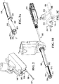
- the drive unit 106 is shown in isolation in Figure 2 .
- the insertion tube 108 includes a drive interface 200 that detachably mounts to a corresponding drive interface 202 on the drive unit 106.
- the insertion tube 108 includes a camera 204 at a distal end of the insertion tube.
- the camera 204 is operably configured to be inserted into a body cavity of a patient to capture body cavity image data representing an interior view of the body cavity.
- FIG. 3 A a portion of the insertion tube 108 is shown in Figure 3 A and includes two adjacently located bores 300 and 302 extending through the insertion tube 108 for receiving a surgical instrument.
- the camera 204 is configured as a stereoscopic camera having a pair of spaced apart imagers 304 and 306 for producing stereoscopic views representing an interior view of the body cavity.
- the camera 204 also includes an illumination source 308 for illuminating the body cavity for capturing images.
- the illumination source 308 may be implemented locally on the camera using a light emitting diode or the illumination source may be remotely located and may deliver the illumination through an optical fiber running through the insertion tube 108.
- the insertion tube 108 is shown isolated from the drive unit 106 in Figure 3 B.
- the instrument 110 is partially inserted through the bore 300 and includes a manipulator 310 and an end effector 312 at a distal end of the instrument.
- the manipulator 310 may include an articulated tool positioner as described in detail in commonly owned PCT patent publication WO2014/201538 entitled "ARTICULATED TOOL POSITIONER AND SYSTEM EMPLOYING SAME" filed on December 20, 2013 and incorporated herein by reference in its entirety.
- the described manipulator in PCT patent publication WO2014/201538 provides for dexterous movement of the end effector 312 through a plurality of articulated segments.
- the end effector 312 may be any of a variety of tools generally used in laparoscopic surgery such as surgical scissors, forceps, and/or an electrocauterization tool.
- the instrument 110 includes an actuator 314 at a proximal end of the instrument that couples to a corresponding interface (not shown) on the drive unit 106 for manipulating the instrument.
- the instrument 110 and the actuator 314 may be configured as disclosed in commonly owned PCT patent publication WO2016/090459 entitled “ACTUATOR AND DRIVE FOR MANIPULATING A TOOL” filed on February 18, 2015 and incorporated herein by reference in its entirety.
- the interface of the drive unit 106 may have a track system (not shown) for advancing and retracting the actuator 314 through the bore 300 in response to the input signals received from the input device 112 to place the end effector 312 at a desired longitudinal offset with respect to the insertion tube 108.
- the camera 204 When the insertion tube 108 is detached as shown in Figure 3 A , the camera 204 remains in a longitudinally extended or in-line state generally oriented along a longitudinal z-axis of the insertion tube 108.
- the camera 204 is mounted on an articulated arm 322 moveable in response to drive forces delivered by the drive interface 202 of the drive unit 106 to the drive interface 200 of the insertion tube 108.
- the articulated arm 322 may be covered by a sterile boot that encloses the articulating mechanism.
- the articulated arm 322 may be configured as disclosed in commonly owned PCT patent publication WO 2017/173524 entitled “Camera Positioning Method and Apparatus for Capturing Images during a Medical Procedure", filed on April 4, 2017 and incorporated herein by reference in its entirety.
- the arm 322 is actuated to move the camera 204, the actuation provided may be used to determine the relative positioning of the camera within the surgical workspace.
- the drive forces delivered by the drive unit 106 cause the camera 204 to move from the longitudinally extended insertion state shown in Figure 3 A and 3 B to a deployed state as shown in Figure 3 C .
- the manipulator 310 of the instrument 110 is actuated to perform dexterous movement to position the end effector 312 for performing various surgical tasks.
- a second instrument 316 is also inserted for performing surgical tasks.
- the second instrument 316 may be similarly configured to the instrument 110, thus having a manipulator 318 and an end effector 320.
- the camera 204 is able to generate images of the body cavity without obstructing movements of the manipulators 310 and 318.
- a patient 400 may have had an incision made in a wall 402 of the patient's abdomen or other body region to provide access to an underlying body cavity 404.
- a wound retractor 406 has been inserted and a cap 408 attached to the underlying wound retractor to provide a seal and a point of entry into the body cavity 404.
- the insertion tube 108 and camera 204 are initially detached from the drive unit 106, and with no instrument 110 loaded at the commencement of a surgical procedure, may be manually inserted through an opening 410 in the cap 408.
- the cap 408 includes an inlet for receiving a fluid flow from an insufflation line 412. Insufflation of the abdominal body cavity with a gas such as carbon dioxide distends the abdomen providing for entry and sufficient operating space for manipulation of surgical instruments during the surgical procedure.
- the insertion tube 108 may be inserted into a body cavity via a natural bodily orifice, i.e. a transanal, transvaginal, or transoral insertion, for example.
- the insertion tube 108 may be initially detached from the drive unit 106 for insertion into a body cavity 404 of the patient 400, but coupled via an image signal line 502 to the slave processor circuit 118 such that images of the interior of the body cavity 404 can be displayed on the display 120.
- neither of the instruments 110 or 316 (shown in Figure 3 C ) is initially received through the respective bores 300 and 302.
- the end effectors 312 and 320 on the instruments 110 and 316 may have sharp cutting edges and are not initially introduced into the body cavity 404 due to the risk of causing damage to tissue prior to the camera 204 being able to capture and relay body cavity image data back to the master processor circuit 114.
- the cap 408 has sufficient compliance to permit the camera 204 to be moved around within the body cavity 404 and aligned to cause the illumination source 308 (shown in Figure 3 A ) to illuminate a desired region of the body cavity 404 for capturing images of the patient's anatomy.
- the camera 204 thus captures body cavity image data, which is relayed back via the slave processor circuit 118 to the master processor circuit 114 for display on the display 120 of the workstation 102.
- FIG. 5 A block diagram of the processor circuit elements of the system 100 is shown in Figure 5 .
- the master processor circuit 114 on the workstation 102 includes a microprocessor 500, a memory 502, a USB interface 504, an input/output 506 and a motion control interface 508, all of which are in communication with the microprocessor 500.
- the input device 112 (shown in Figure 1 ) communicates using a USB protocol and the USB interface 504 receives input signals produced by the input device in response to movements of the hand controllers 122 and 124.
- the microprocessor 500 processes the input signals and causes the motion control interface 508 to transmit control signals to the instrument processor circuit 118 via the interface cable 116.
- the memory 502 provides storage for program codes 520 for directing the microprocessor 500 to perform various functions.
- the memory 502 also includes storage for data, such as instrument parameters 522.
- the slave processor circuit 118 on the instrument cart 104 includes a microprocessor 580, a memory 582, a communications interface 584, and a drive control interface 586, all of which are in communication with the microprocessor.
- the microprocessor 580 receives the control signals at the communications interface 584 over the interface cable 116 from the master processor circuit 114 of the workstation 102.
- the microprocessor 580 then processes the control signals, which are output by the drive control interface 586 and cause the drive unit 106 to produce drive forces for moving the instruments 110 and 316 and the camera 204.
- the memory 582 provides storage for program codes 590 and other control data 592 associated with operation of the instrument cart 104.
- the master processor circuit 114 acts as a master subsystem for receiving operator input from the input device 112, while the slave processor circuit 118, drive unit 106 and instrument 110 act as a slave subsystem in responding to the operator input.
- functions performed by the master and slave processor circuits 114 and 118 may be performed by a single processor circuit, operably configured to both receive the input signals and generate the drive signals.
- FIG. 6 a flowchart depicting blocks of code for directing the master and slave processor circuits 114 and 118 during insertion of an instrument into the body cavity 404 of the patient 400 is shown generally at 600.
- the blocks generally represent codes that may be read from the master processor memory 502 and slave processor memory 582 for directing the microprocessors 500 and 580 to perform various functions.
- the actual code to implement each block may be written in any suitable program language, such as C, C++, C#, Java, and/or assembly code, for example.
- the process begins at block 602, which directs the microprocessor 580 of the slave processor circuit 118 to receive body cavity image data.
- the body cavity image data is captured by the camera 204 and represents an interior view of the body cavity 404.
- the insertion tube 108 may be moved around within the body cavity 404 to position the camera 204 to view various anatomical features within the body cavity 404.
- the camera 204 is oriented to provide images of an ovary 414 of the patient 400.
- the body cavity image data is then relayed back via the interface cable 116 for receipt by the microprocessor 500 of the master processor circuit 114.
- Block 604 then directs the microprocessor 500 of the master processor circuit 114 to determine instrument parameters associated with physical extents of the instrument to be inserted into the body cavity.
- each of the instruments 110 and 316 shown in Figure 3 will have associated parameters that identify attributes of the instrument such its physical length, the type of end effector attached, offset in relation to the bore 300 and camera, actuation limits, etc. These parameters will generally have already been loaded into the memory 502 of the master processor circuit 114 in the instrument parameters memory location 522.
- Block 606 then directs the microprocessor 500 to read the instrument parameters from the memory location 522 for each instrument and to determine an instrument envelope based on the instrument parameters.
- the instrument envelope corresponding to the instrument 110 is depicted in broken lines at 416 in Figures 4 and 5 and identifies a region through which the instrument 110 is capable of physically moving when inserted into the body cavity 404. Note that as shown in Figure 4 , the instrument 110 is not yet inserted through the insertion tube 108. Since the instrument 110 will be eventually inserted through the bore 300 of the insertion tube 108, the orientation of the instrument is determined by the orientation of the bore and the insertion tube.
- the instrument envelope 416 of the instrument 110 may have a generally cylindrical shape extending outwardly with respect to a longitudinal axis of the bore 300 and illustrates the potential reach of the instrument.
- the physical reach of the instrument 110 may be calculated as a length of the instrument when fully inserted in the bore 300, as defined in the instrument parameters memory location 522.
- the instrument envelope 416 may represent a 3 D volume, for example representing the total volume which may be occupied by the instrument when inserted through the insertion tube 108.
- the envelope may represent a physical reach of the instrument in at least one degree of freedom (for example along a longitudinal axis of the bore 300 ) associated with the instrument prior to insertion of the instrument into the body cavity.
- Block 608 then directs the microprocessor 500 to generate a view based on the body cavity image data being captured in real-time from the camera 204.
- the view thus represents current conditions within the body cavity 404.
- An example of an image represented by the body cavity image data is depicted in Figure 7 A at 700.
- the camera 204 captures an image within a field of view illuminated by the illumination source 308, in this case including the left ovary 414, a portion of the colon 702, the uterus 704, the left fallopian tube 706, as well as the right ovary 708 and right fallopian tube 709.
- the body cavity image data may be streamed from the camera 204 as a real-time sequence of high-definition (HD) video frames for viewing as either 2 D or 3 D video on the display 120.
- HD high-definition
- the master processor circuit 114 would need to be capable of generating the 3 D point cloud, determining the instrument envelope, and generating the necessary projections at a reasonable frame rate (for example at 15 - 30 frames per second for HD video data).
- Block 610 then directs the microprocessor 500 to generate a view including an envelope overlay image representing the determined instrument envelope 416.
- the view generated at block 610 represents a prediction of the physical extents of the instrument 110 prior to the instrument actually being inserted into the body cavity.
- An example overlay image is shown in Figure 7 B at 710.
- the instrument is represented by a cylindrical shape shown as would appear from the perspective of the camera 204 with a distal end 712 representing the end effector.
- the camera 204 is shown longitudinally extended for initial positioning of the insertion tube 108 prior to inserting instruments through the insertion tube.
- the camera captures a view (indicated within the broken lines 1400 ) of the body cavity 404 from the perspective of the camera 204 when longitudinally extended and located in at the position P 0 before being moved into the deployed state (as shown at P 1 in Figure 14 B ).
- the camera 204 is shown oriented in the deployed state, which would be used for viewing of the body cavity 404 during a surgical procedure.
- the camera 204 is moved upwardly and angled down to provide a view 1402 of the surgical workspace within which the instruments are capable of reaching (shown in broken outline at 1404 ) and to facilitate insertion of the instruments through the insertion tube 108 and subsequent manipulation thereof.
- the view 1400 in Figure 14 A thus differs in perspective from the view in Figure 14 B due to the different positioning P 0 and P 1 .
- the master processor circuit 114 is configured to distort the image captured by the camera 204 when in the position P 0 prior to display on the display 120.
- the degree of distortion of the image is selected to make the displayed image appear as if it were captured by the camera 204 in the deployed state P 1 so that the system 100 provides the surgeon with a displayed perspective that corresponds to the perspective displayed during the remainder of the surgical procedure once the camera 204 is deployed.
- the coordinates of the positions P 0 and P 1 may be determined based on parameters associated with actuation of the articulated arm 322. When the camera 204 is in the longitudinally extended state at position P 0 the image is distorted with respect to the image captured in the position P 1 .
- FIG. 15 A An example of the image generated for the position P 0 of the camera 204 is shown in Figure 15 A and the boundaries of the display 120 or other display window are indicated as a rectangle ABCD.
- the image captured by the camera 204 at P 0 may be distorted to generate an acute trapezoid as shown in Figure 15 B at 1500. Since the distorted image 1500 no longer corresponds with the boundaries of the display 120 (i.e. A, B, C, D), the distorted image would need to be scaled to fit within the display boundaries ABCD. This results in some truncation of the originally captured image as shown at 1502 in Figure 15 B .
- the distorted image may be formed using the image provided by one of the stereoscopic imagers of the camera 20 4.
- a 2 D representation of the envelope overlay images may then be displayed over the distorted image. Since only the perspective from a fixed and known position P 1 is required, generation of the distorted image may be based on a fixed distortion filter (i.e. a trapezoid distortion with parameters corresponding to the difference between the camera positions P 0 and P 1 ). The generation of the image would thus not be processor intensive since complex image transformation is not required. The estimation of the distorted view would thus produce a 2 D image and a 2 D representation of the envelope overlay images would accordingly be used when forming a composite image.
- a fixed distortion filter i.e. a trapezoid distortion with parameters corresponding to the difference between the camera positions P 0 and P 1 .
- the process 600 then continues at block 612, which directs the microprocessor 500 to generate display signals operable to display a composite view of the interior of the body cavity on the display 120 associated with the workstation 102.
- An example composite view is shown in Figure 7 C at 720 and is based on the body cavity image data captured by the camera 204 and includes the envelope overlay image 710.
- the composite view 720 illustrates the relative proximity between the instrument 110 and anatomy such as the uterus 704 and ovary 414 for the current camera position.
- the body cavity image 700 and envelope overlay image 710 may be generated at video frame rates in near-real time so that the display on the display 120 is continually updated as the insertion tube 108 is moved within the body cavity 404.
- the envelope overlay image 710 may be displayed as a shaded region or other representation of the instrument envelope. Since the envelope overlay image 710 is based on physical parameters of the actual instrument 110, the composite view 720 thus provides a prior indication of an extent that the instrument will have, once inserted through the insertion tube 108 into the body cavity 404.
- the display 120 may be capable of displaying the stereoscopic images for viewing through a pair of 3 D viewing spectacles to provide a 3 D view of the interior of the body cavity 404.
- the captured 2 D images produced by each of the pair of spaced apart imagers 304 and 306 may be presented in a format suitable for viewing with spectacles having colored filters, polarization filters, or actively shuttered spectacles.
- the display may be configured to display each image only to one of the operator's eyes using separate displays in a head mounted display.
- 3 D image capture techniques may be used to generate data having 3 D information.
- a time of flight camera may be used to generate image data including three-dimensional spatial information obtained on a pixel-by-pixel basis by determining the time that controlled illumination takes to be reflected back from anatomical features.
- a camera in combination with a structured light source for illuminating the interior of the body cavity may be used to facilitate determination of three-dimensional spatial information.
- the camera 204 includes the pair of spaced apart imagers 304 and 306 (shown in Figure 3 A ) and each image sensor is operably configured to capture an image of the interior of the body cavity 404 from a different perspective within a coordinate frame [ x v , y v , z v ] .
- the coordinate frame [ x v , y v , z v ] has an origin o v located at a center of the camera 204.
- the origin of the coordinate frame may be located elsewhere on the insertion tube 108.
- the 2 D images produced by the imagers 304 and 306 may be processed to generate a 3 D point cloud using various open source or propriety library functions.
- the point cloud represents a set of points P i , such as the points P 0 and P 1 shown in Figure 8 .
- the point cloud points P i are generated from the 2 D images by determining a distance between common points on the surface as represented by the separate images produced by the spaced apart imagers 304 and 306. Generation of the point cloud thus provides 3 D coordinates within the coordinate frame [ x v , y v , z v ] of points P i representing surfaces of anatomical features such as the ovary 414, uterus 704, and fallopian tube 706.
- the instrument parameters stored in the memory location 522 of the master processor memory 502 are then used to determine the range of possible motion of the instrument 110 with respect to the bore 300 within the coordinate frame [ x v , y v , z v ] .
- the instrument parameters 522 may include a maximum distance between an opening of the bore 300 and the end effector 312 of the instrument 110 when the instrument is fully inserted and advanced through the bore.
- the instrument parameters 522 may further include an offset distance between the opening of the bore 300 and the origin of the coordinate frame [ x v , y v , z v ] at the camera 204.
- the extent of the cylindrical instrument envelope 802 may then be converted into a point cloud of points P j or may be represented other 3 D representation techniques, such as a polygon mesh (not shown) having vertices located on the surface of the cylindrical volume.
- the instrument parameters 522 may also include articulation information defining a manipulation region within which the manipulator 310 (shown in Figure 3 C ) is capable of moving the end effector 312.
- the cylindrical instrument envelope 802 may be further expanded to include the manipulation region that the instrument 110 will have once inserted.
- the instrument envelope may thus be displayed as an outline of a volume 804 demarcating extents for manipulation of the instrument in response to movements of the input device 112 (shown in Figure 1 ).
- the shape of the volume 804 is dependent on the type of manipulator 310 that is implemented to provide the dexterous movement of the instrument 110.
- Table 1 A listing of typical instrument parameters that may be saved in the instrument parameters memory location 522 are listed in Table 1 below.
- Table 1 q ins z-position of the insertion tube ⁇ 1 Angle that represents how much the s-segment is bent ⁇ 1 Angle that represents the plane in which the s-segment is bent.
- ⁇ 2 Angle that represents how much the distal segment is bent ⁇ 1 Angle that represents the plane in which the distal segment is bent.
- Generation of the envelope overlay image 710 may involve generating 3 D image data in a similar format to the image data produced by the camera 204 to facilitate generation of a 3 D composite view 720 by overlaying the instrument envelope image over the body cavity image data.
- the microprocessor 500 may be operably configured to generate projections of a 3 D envelope overlay image 710 onto 2 D planes corresponding to the body cavity images generated by the pair of spaced apart imagers 304 and 306. The resulting 2 D envelope projections may then be combined with the original body cavity images as an overlay image to produce a 3 D view of the envelope overlay image 710 within a 3 D composite view.
- the overlay image may be displayed as a shaded or a semi-transparent 3 D region in the resulting 3 D composite view. In other embodiments the overlay image may be displayed showing only an outline of the instrument envelope. Standard open source image overlay functions are generally available for performing a combination of two or more images and may be used to implement the process in near real time.
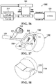
- FIG. 16 a block diagram illustrating the processing and generation of signals by the microprocessor 500 for producing the 3 D composite view is shown at 1600.
- the microprocessor 500 of the master processor circuit 114 receives left and right images from the spaced apart left and right imagers 304 and 306 of the camera 204 and generates a 3 D point cloud.
- An available software tool such as OpenGL may be implemented on the microprocessor 500 to render a 3 D scene of the point cloud as well as the 3 D envelope overlay.
- the 3 D point cloud and 3 D envelope are rendered together so that the 3 D envelope is clipped where it intersects the point cloud.
- the known position of the camera in relation to the z-axis the insertion tube 108 may then be used to create two views; one view for the left imager and another view for the right imager. Finally, the left and right views are rendered without the point cloud and output to the image processing block, which creates the left and right composite views.
- the insertion tube 108 and camera 204 are initially detached from the drive interface 202 of the drive unit 106, facilitating positioning of the camera by hand to receive a desired interior view of the body cavity 404 based on the composite view.
- the operator ensures that the insertion tube 108 is located such that the instrument 110 can be safely inserted and once inserted will be disposed to provide an adequate range of manipulation for performing the desired surgical process.
- the drive unit may then be connected to the drive unit 106 and further positioning of the camera 204, such as for example moving to the deployed state shown in Figure 3 C , may then be performed under control of the master processor circuit 114 and slave processor circuit 118.
- the microprocessor 500 of the master processor circuit 114 may be directed to discontinue display of the envelope overlay image, since the instrument 110 would then move into the view in place of the instrument envelope.
- the insertion tube 108 once coupled to the drive interface 202 of the drive unit 106 may need to be repositioned for various reasons, including a need to adjust the available surgical workspace that is within reach of the manipulation range of the instruments 110 and second instrument 316.
- repositioning of the insertion tube may be accomplished by repositioning the drive unit 106 manually (by a bed side nurse or surgeon other than the surgeon operating the workstation 102 ) .
- the surgeon operating the workstation 102 may generate actuation signals at the workstation 102 (for example by moving the hand controllers 122 ) to cause the insertion tube 108 to be repositioned.
- the system 100 may be first configured to decouple the instruments 110 and 316 and/or camera 204 from the input device 112 so that further movement within the body cavity 404 is inhibited.
- decoupling of the instruments 110 and 316 may be caused by the surgeon depressing a clutch pedal 126 that prevents further changes to the instrument actuation signals such that the instrument cart 104 inhibits further movements that could cause damage to the patient's tissues or organs.
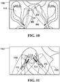
- instrument envelope overlay images 900 and 902 when in the decoupled state instrument envelope overlay images 900 and 902 (similar to that shown at 804 in Figure 8 ) may be generated and displayed for each of the instruments 110 and 316 to indicate the respective instrument manipulation regions while repositioning of the insertion tube 108 to a safe and desired position.
- a resulting composite view of the instrument envelope overlay images 900 and 902 as viewed on the display 120 (from the perspective of the camera 204 ) is shown at 1000.
- the composite view 1000 depicted in Figure 10 is a "birds-eye" view from the view point of the camera 204 in its deployed state as shown in Figure 9 .
- the composite view 1000 thus depicts the possible range of manipulation 900 and 902 for each of the instruments 316 and 110 and provides information to aid in the repositioning.
- the surgeon may wish to perform surgical operations in a specific anatomical region such as the ovary 414.
- a composite view 1100 may display an enlarged portion of the patient's anatomy along with the instrument envelope overlay images 1100 and 1102 depicting the associated possible range of manipulation of the instruments 110 and 316.
- the camera 204 is integrally coupled to and part of the insertion tube 108.
- the camera may be received as a separate unit in an insertion tube.
- an insertion tube 1200 is sized to permit first and second instruments 1202 and 1204 and a camera 1206 to be received.
- the camera 1206 is configured as a separate unit having its own sheath 1208.
- the insertion tube 1200 may still be inserted through the opening 410 in the cap 408 ( Figure 4 ) or other body orifice.
- the camera 1206 and first and second instruments 1202 and 1204 are all independently movable through the insertion tube 1200.
- the insertion tube 1200 may have separated bores for accommodating the camera 1206, and each of the first and second instruments 1202 and 1204.
- the insertion tube 1200 may be inserted partway into the body cavity 404 through the opening 410 before the camera 1206 and instruments 1202 and 1204 are inserted. Subsequently, when the camera 1206 is inserted and reaches an end 1210 of the insertion tube 1200 the composite images depicting instrument envelopes similar to those shown in Figures 9 to 11 may be generated to allow the insertion tube to be positioned appropriately, as generally disclosed above.
- the instruments 1202 and 1204 can be inserted and would move into view in place of the respective instrument envelopes.
- the camera and instruments are independently movable and may be inserted through separate incisions.
- a camera may be coupled to a first manipulator associated with a robotic surgery system and an instrument may be coupled to a second manipulator, both of which are independently moveable.
- the location of the instrument will not be constrained by an instrument bore (as in the case of the bore 300 of the insertion tube 108 ) but rather by the point at the incision through which the instrument is inserted into the body cavity.
- the instrument parameters 522 may then be used to determine the possible physical extent of the instrument within the body cavity 404.
- the body cavity image data may be processed by the master processor circuit 114 to identify anatomical features within a composite view as shown generally at 1300.
- the master processor circuit 114 may be operably configured to identify major organs such as the ovary 414, uterus 704, colon 702, etc.
- the master processor circuit 114 may implement machine-learning techniques to train an image recognition algorithm to recognize anatomical features under various conditions.
- the image recognition algorithm may be neural network based and may be trained using a set of labeled training images in which features such as the fallopian tube 706, and ovary 414 have been previously manually labeled by an operator.
- an additional overlay image identifying at least one anatomical feature within the body cavity 404 may be generated.
- the composite view 1300 in addition to the body cavity image 700 and envelope overlay image 710 (shown in Figure 7 ) may also include highlighting or other overlay identifying some anatomical features. For example, relevant anatomical features in the composite view 1300 may be displayed together with shading or semi-transparent overlay colors to indicate different anatomical features.
- the master processor circuit 114 may determine whether there are any regions of potential encroachment of between the instrument envelope 710 and an identified anatomical feature, in which case an alert signal may be generated.
- the alert signal may take the form of a further warning overlay image 1302 for display as part of the composite image.
- the warning overlay image 1302 may also be accompanied by an audible warning or by haptic feedback via the input device 112.
- the alert signal may further be transmitted to the slave processor circuit 118 to cause the drive unit 106 to generate drive signals that limit further movement of the drive unit 106 and the insertion tube 108 to prevent or otherwise limit full movement of the camera and/or instruments into the region of potential encroachment.
- a similar alert signal may also be generated when repositioning the insertion tube 108 to highlight a potential encroachment of between the instrument envelope and an identified anatomical feature. Repositioning of the insertion tube 108 may involve causing the insertion tube to pivot about the location of the incision or causing a portion of the insertion tube to articulate along its length to reposition a distal end of the insertion tube.
- Generation of the overlay image for highlighting the anatomical features may involve the master processor circuit 114 processing the body cavity image data using the image recognition algorithm to identify surface regions associated with the anatomy in the area of the surgical worksite. Each surface region may then be represented using a polygon mesh representation or other method. A similar polygon mesh representation may also be generated for the envelope overlay image 710 and points of proximity or intersection between the instrument envelope and the anatomy surface region may be determined. Standard 3 D surface intersection library functions for this purpose are available in open source libraries of functions.
- the overlay image may be generated as a 3 D volume reachable by manipulating the instruments 110 and 316, as shown at 1700 in broken lines.
- the volume 1700 has a first portion 1702 within which the instruments 110 and 316 are freely able to move within the constraints provided by the manipulators 310 and 318.
- the volume 1700 has a second portion 1704 proximate the insertion tube 108 that may be encumbered by the camera 204, even when in the deployed state.
- a non-manipulatable portion of the instruments 110 and 316 proximate the insertion tube 108 may also have a role in determining the second portion 1704.
- a remaining workable volume is thus enclosed within the volume 1700, which may be displayed on the display 120 to indicate this workable volume.
- the workable volume is the region where the end-effectors can reach by manipulating the instruments 110 and 316 and moving the instruments in the z-axis direction.
- the workable volume 1700 would thus be dependent on the deployed position of the camera 204 and the articulated arm 322 supporting the camera, and also on the structure of the instruments 110 and 316.
- the workable volume 1700 is shown from a different perspective in Figure 18 .
- the first portion 1702 and second portion 1704 may be otherwise shaped depending on the structural features of the insertion tube 108, camera 204, and the instruments 110 and 316.
- the workable volume 1700 may be generated based on the instrument parameters as described above.
- the above disclosed embodiments provide a representation of the instrument prior to actual insertion into the patient and thus prevent inadvertent damage to tissue or organs of the patient.
- the surgeon or other operator is able to safely view the interior of the body cavity and position the camera to capture images of the surgical worksite.
- the generated composite view including the overlay image provides a visual cue to the surgeon of possible engagement between the instrument and sensitive anatomy, thus facilitating positioning of the camera prior to insertion of the instrument.
Landscapes
- Health & Medical Sciences (AREA)
- Life Sciences & Earth Sciences (AREA)
- Engineering & Computer Science (AREA)
- Surgery (AREA)
- Nuclear Medicine, Radiotherapy & Molecular Imaging (AREA)
- Medical Informatics (AREA)
- Veterinary Medicine (AREA)
- General Health & Medical Sciences (AREA)
- Public Health (AREA)
- Biomedical Technology (AREA)
- Heart & Thoracic Surgery (AREA)
- Animal Behavior & Ethology (AREA)
- Molecular Biology (AREA)
- Physics & Mathematics (AREA)
- Radiology & Medical Imaging (AREA)
- Pathology (AREA)
- Optics & Photonics (AREA)
- Biophysics (AREA)
- Robotics (AREA)
- Signal Processing (AREA)
- Computer Vision & Pattern Recognition (AREA)
- General Physics & Mathematics (AREA)
- Theoretical Computer Science (AREA)
- Gynecology & Obstetrics (AREA)
- Oral & Maxillofacial Surgery (AREA)
- Artificial Intelligence (AREA)
- Evolutionary Computation (AREA)
- Endoscopes (AREA)
- Human Computer Interaction (AREA)
Applications Claiming Priority (1)
| Application Number | Priority Date | Filing Date | Title |
|---|---|---|---|
| US15/961,507 US10058396B1 (en) | 2018-04-24 | 2018-04-24 | System and apparatus for insertion of an instrument into a body cavity for performing a surgical procedure |
Publications (2)
| Publication Number | Publication Date |
|---|---|
| EP3560411A2 true EP3560411A2 (fr) | 2019-10-30 |
| EP3560411A3 EP3560411A3 (fr) | 2019-11-20 |
Family
ID=63208876
Family Applications (1)
| Application Number | Title | Priority Date | Filing Date |
|---|---|---|---|
| EP19170809.8A Pending EP3560411A3 (fr) | 2018-04-24 | 2019-04-24 | Système et appareil permettant d'insérer un instrument dans une cavité corporelle pour effectuer une procédure chirurgicale |
Country Status (3)
| Country | Link |
|---|---|
| US (5) | US10058396B1 (fr) |
| EP (1) | EP3560411A3 (fr) |
| CA (1) | CA3034919A1 (fr) |
Families Citing this family (37)
| Publication number | Priority date | Publication date | Assignee | Title |
|---|---|---|---|---|
| CN110279427B (zh) * | 2012-12-10 | 2024-01-16 | 直观外科手术操作公司 | 图像采集装置和可操纵装置活动臂受控运动过程中的碰撞避免 |
| US10058396B1 (en) | 2018-04-24 | 2018-08-28 | Titan Medical Inc. | System and apparatus for insertion of an instrument into a body cavity for performing a surgical procedure |
| US11559298B2 (en) | 2018-07-16 | 2023-01-24 | Cilag Gmbh International | Surgical visualization of multiple targets |
| US11612438B2 (en) * | 2018-09-05 | 2023-03-28 | Point Robotics Medtech Inc. | Navigation system and method for medical operation by a robotic system using a tool |
| GB2577718B (en) * | 2018-10-03 | 2022-08-24 | Cmr Surgical Ltd | Feature identification |
| GB2577719B (en) * | 2018-10-03 | 2023-04-26 | Cmr Surgical Ltd | Navigational aid |
| US11147434B2 (en) | 2018-10-10 | 2021-10-19 | Titan Medical Inc. | Systems, methods, and apparatuses for capturing images during a medical procedure |
| US20200154094A1 (en) * | 2018-11-09 | 2020-05-14 | Titan Medical Inc. | Stereoscopic imaging apparatus for use in confined spaces |
| WO2020156667A1 (fr) | 2019-01-31 | 2020-08-06 | Brainlab Ag | Planification de trajectoire virtuelle |
| EP3937822A4 (fr) * | 2019-03-14 | 2022-12-21 | Covidien LP | Systèmes chirurgicaux robotisés et leurs chariots de bras robotisés |
| JP6867654B2 (ja) | 2019-03-15 | 2021-05-12 | リバーフィールド株式会社 | 医用ロボットシステムの力覚表示装置および力覚表示方法 |
| US12257013B2 (en) | 2019-03-15 | 2025-03-25 | Cilag Gmbh International | Robotic surgical systems with mechanisms for scaling camera magnification according to proximity of surgical tool to tissue |
| US11166774B2 (en) * | 2019-04-17 | 2021-11-09 | Cilag Gmbh International | Robotic procedure trocar placement visualization |
| US10939970B2 (en) | 2019-05-22 | 2021-03-09 | Titan Medical Inc. | Robotic surgery system |
| CA3143200A1 (fr) * | 2019-06-26 | 2020-12-30 | Titan Medical Inc. | Systemes de barriere sterile et procedes pour systemes de chirurgie robotique |
| US20220392087A1 (en) * | 2019-11-08 | 2022-12-08 | Intuitive Surgical Operations, Inc. | Systems and methods for registering an instrument to an image using point cloud data |
| US11219501B2 (en) | 2019-12-30 | 2022-01-11 | Cilag Gmbh International | Visualization systems using structured light |
| US11284963B2 (en) | 2019-12-30 | 2022-03-29 | Cilag Gmbh International | Method of using imaging devices in surgery |
| US12053223B2 (en) | 2019-12-30 | 2024-08-06 | Cilag Gmbh International | Adaptive surgical system control according to surgical smoke particulate characteristics |
| US12207881B2 (en) | 2019-12-30 | 2025-01-28 | Cilag Gmbh International | Surgical systems correlating visualization data and powered surgical instrument data |
| US11776144B2 (en) * | 2019-12-30 | 2023-10-03 | Cilag Gmbh International | System and method for determining, adjusting, and managing resection margin about a subject tissue |
| US11648060B2 (en) | 2019-12-30 | 2023-05-16 | Cilag Gmbh International | Surgical system for overlaying surgical instrument data onto a virtual three dimensional construct of an organ |
| US12453592B2 (en) | 2019-12-30 | 2025-10-28 | Cilag Gmbh International | Adaptive surgical system control according to surgical smoke cloud characteristics |
| US11759283B2 (en) * | 2019-12-30 | 2023-09-19 | Cilag Gmbh International | Surgical systems for generating three dimensional constructs of anatomical organs and coupling identified anatomical structures thereto |
| US11744667B2 (en) | 2019-12-30 | 2023-09-05 | Cilag Gmbh International | Adaptive visualization by a surgical system |
| US11832996B2 (en) | 2019-12-30 | 2023-12-05 | Cilag Gmbh International | Analyzing surgical trends by a surgical system |
| US12002571B2 (en) | 2019-12-30 | 2024-06-04 | Cilag Gmbh International | Dynamic surgical visualization systems |
| US11896442B2 (en) | 2019-12-30 | 2024-02-13 | Cilag Gmbh International | Surgical systems for proposing and corroborating organ portion removals |
| US20220051424A1 (en) * | 2020-08-13 | 2022-02-17 | Opsis Health, Inc. | Object-recognition training |
| EP4202527A4 (fr) * | 2020-08-24 | 2024-02-14 | FUJIFILM Corporation | Dispositif de traitement d'image, procédé et programme |
| CN115120353B (zh) * | 2020-12-15 | 2025-08-12 | 深圳市精锋医疗科技股份有限公司 | 手术机器人、计算机可读存储介质及控制装置 |
| US20240155241A1 (en) * | 2021-06-21 | 2024-05-09 | Sony Group Corporation | Medical observation system, information processing device, and information processing method |
| JP1713324S (ja) * | 2021-09-14 | 2022-04-22 | 医療用ロボット | |
| US20230156174A1 (en) * | 2021-11-17 | 2023-05-18 | 3Dintegrated Aps | Surgical visualization image enhancement |
| USD1099916S1 (en) * | 2022-12-13 | 2025-10-28 | Conavi Medical Corp. | Display screen or portion thereof with a graphical user interface |
| US12440291B2 (en) | 2022-12-27 | 2025-10-14 | Conavi Medical Inc. | Systems and methods for unpowered release and retraction of robotic tools in a robotic surgical system |
| JP1761873S (ja) * | 2023-04-18 | 2024-01-19 | 医療用ロボット |
Citations (3)
| Publication number | Priority date | Publication date | Assignee | Title |
|---|---|---|---|---|
| WO2014201538A1 (fr) | 2013-06-19 | 2014-12-24 | Titan Medical Inc. | Dispositif articulé de positionnement d'outil et système l'utilisant |
| WO2016090459A1 (fr) | 2014-12-11 | 2016-06-16 | Titan Medical Inc. | Actionneur et mécanisme d'entraînement pour la manipulation d'un outil |
| WO2017173524A1 (fr) | 2016-04-07 | 2017-10-12 | Titan Medical Inc. | Procédé et appareil de positionnement de caméra pour capturer des images pendant une procédure médicale |
Family Cites Families (25)
| Publication number | Priority date | Publication date | Assignee | Title |
|---|---|---|---|---|
| US7630752B2 (en) | 2002-08-06 | 2009-12-08 | Stereotaxis, Inc. | Remote control of medical devices using a virtual device interface |
| FR2855292B1 (fr) | 2003-05-22 | 2005-12-09 | Inst Nat Rech Inf Automat | Dispositif et procede de recalage en temps reel de motifs sur des images, notamment pour le guidage par localisation |
| EP1691666B1 (fr) * | 2003-12-12 | 2012-05-30 | University of Washington | Systeme de guidage et d'interface en 3d pour catheterscope |
| US7846103B2 (en) * | 2004-09-17 | 2010-12-07 | Medical Equipment Diversified Services, Inc. | Probe guide for use with medical imaging systems |
| US8182422B2 (en) * | 2005-12-13 | 2012-05-22 | Avantis Medical Systems, Inc. | Endoscope having detachable imaging device and method of using |
| US9492240B2 (en) | 2009-06-16 | 2016-11-15 | Intuitive Surgical Operations, Inc. | Virtual measurement tool for minimally invasive surgery |
| US11576736B2 (en) * | 2007-03-01 | 2023-02-14 | Titan Medical Inc. | Hand controller for robotic surgery system |
| WO2008104082A1 (fr) * | 2007-03-01 | 2008-09-04 | Titan Medical Inc. | Procédés, systèmes et dispositifs pour une entrée tridimensionnelle, et procédés et systèmes de commande basés sur ceux-ci |
| US9089256B2 (en) | 2008-06-27 | 2015-07-28 | Intuitive Surgical Operations, Inc. | Medical robotic system providing an auxiliary view including range of motion limitations for articulatable instruments extending out of a distal end of an entry guide |
| US8864652B2 (en) | 2008-06-27 | 2014-10-21 | Intuitive Surgical Operations, Inc. | Medical robotic system providing computer generated auxiliary views of a camera instrument for controlling the positioning and orienting of its tip |
| WO2011150376A1 (fr) | 2010-05-28 | 2011-12-01 | C.R. Bard, Inc. | Appareil convenant à une utilisation avec un système de guidage d'insertion d'aiguille |
| WO2014047152A1 (fr) * | 2012-09-19 | 2014-03-27 | The Regents Of The University Of Michigan | Système de ciblage neural intra-opératif avancé et procédé associé |
| JP6542252B2 (ja) * | 2014-03-17 | 2019-07-10 | インテュイティブ サージカル オペレーションズ, インコーポレイテッド | 遠隔操作医療システムにおける器具のオフスクリーン表示のためのシステム及び方法 |
| US10334227B2 (en) | 2014-03-28 | 2019-06-25 | Intuitive Surgical Operations, Inc. | Quantitative three-dimensional imaging of surgical scenes from multiport perspectives |
| KR102387096B1 (ko) * | 2014-03-28 | 2022-04-15 | 인튜어티브 서지컬 오퍼레이션즈 인코포레이티드 | 시계 내의 기기들의 정량적 3차원 시각화 |
| WO2016184746A1 (fr) * | 2015-05-18 | 2016-11-24 | Koninklijke Philips N.V. | Rétroaction de précision pendant un processus de biopsie guidée par image |
| EP3318194A4 (fr) * | 2015-07-02 | 2019-04-03 | Olympus Corporation | Appareil d'observation à ultrasons, procédé de fonctionnement d'appareil d'observation à ultrasons et programme de fonctionnement d'appareil d'observation à ultrasons |
| KR102518492B1 (ko) | 2016-01-19 | 2023-04-05 | 타이탄 메디칼 아이엔씨. | 로봇 수술 시스템용 그래픽 사용자 인터페이스 |
| CN114027987B (zh) * | 2016-06-30 | 2024-09-13 | 直观外科手术操作公司 | 在图像引导程序期间以多种模式显示指导信息的图形用户界面 |
| US11071593B2 (en) * | 2017-07-14 | 2021-07-27 | Synaptive Medical Inc. | Methods and systems for providing visuospatial information |
| JP7016681B2 (ja) * | 2017-12-01 | 2022-02-07 | ソニー・オリンパスメディカルソリューションズ株式会社 | 内視鏡システム |
| US11058497B2 (en) * | 2017-12-26 | 2021-07-13 | Biosense Webster (Israel) Ltd. | Use of augmented reality to assist navigation during medical procedures |
| JP7159577B2 (ja) * | 2018-03-20 | 2022-10-25 | ソニーグループ株式会社 | 内視鏡システム、制御方法、情報処理装置、およびプログラム |
| JP2019185002A (ja) * | 2018-04-11 | 2019-10-24 | ソニー株式会社 | 顕微鏡システム及び医療用光源装置 |
| US10058396B1 (en) | 2018-04-24 | 2018-08-28 | Titan Medical Inc. | System and apparatus for insertion of an instrument into a body cavity for performing a surgical procedure |
-
2018
- 2018-04-24 US US15/961,507 patent/US10058396B1/en active Active
- 2018-08-02 US US16/053,232 patent/US10245113B1/en active Active
-
2019
- 2019-02-12 US US16/273,442 patent/US11000339B2/en not_active Expired - Fee Related
- 2019-02-25 CA CA3034919A patent/CA3034919A1/fr active Pending
- 2019-04-24 EP EP19170809.8A patent/EP3560411A3/fr active Pending
-
2021
- 2021-04-12 US US17/227,617 patent/US11779418B2/en active Active
-
2023
- 2023-10-05 US US18/481,912 patent/US20240099794A1/en not_active Abandoned
Patent Citations (3)
| Publication number | Priority date | Publication date | Assignee | Title |
|---|---|---|---|---|
| WO2014201538A1 (fr) | 2013-06-19 | 2014-12-24 | Titan Medical Inc. | Dispositif articulé de positionnement d'outil et système l'utilisant |
| WO2016090459A1 (fr) | 2014-12-11 | 2016-06-16 | Titan Medical Inc. | Actionneur et mécanisme d'entraînement pour la manipulation d'un outil |
| WO2017173524A1 (fr) | 2016-04-07 | 2017-10-12 | Titan Medical Inc. | Procédé et appareil de positionnement de caméra pour capturer des images pendant une procédure médicale |
Also Published As
| Publication number | Publication date |
|---|---|
| US20190321118A1 (en) | 2019-10-24 |
| US11779418B2 (en) | 2023-10-10 |
| US11000339B2 (en) | 2021-05-11 |
| US10058396B1 (en) | 2018-08-28 |
| CA3034919A1 (fr) | 2019-10-24 |
| EP3560411A3 (fr) | 2019-11-20 |
| US10245113B1 (en) | 2019-04-02 |
| US20210228295A1 (en) | 2021-07-29 |
| US20240099794A1 (en) | 2024-03-28 |
Similar Documents
| Publication | Publication Date | Title |
|---|---|---|
| US11779418B2 (en) | System and apparatus for positioning an instrument in a body cavity for performing a surgical procedure | |
| US12165268B2 (en) | Remote surgical mentoring | |
| US12161419B2 (en) | Robot-assisted setup for a surgical robotic system | |
| US20250143736A1 (en) | Medical manipulator and method of controlling the same | |
| US8123675B2 (en) | System and method for augmentation of endoscopic surgery | |
| JP5372225B2 (ja) | コンピュータディスプレイ画面の境界領域に表示されるツール位置および識別指標 | |
| JP7722365B2 (ja) | 手術中に画像取込装置を制御するためのシステム、方法、および、コンピュータプログラム製品 | |
| WO2019116592A1 (fr) | Dispositif pour ajuster une image d'affichage d'endoscope, et système de chirurgie | |
| KR102596096B1 (ko) | 원격조작 시스템에서 기구 내비게이터를 디스플레이하기 위한 시스템들 및 방법들 | |
| JP7800010B2 (ja) | 医療用アーム制御システム、医療用アーム制御方法、及びプログラム | |
| CN114760903A (zh) | 用于在外科手术期间控制图像捕获设备的方法、装置、以及系统 | |
| JP4027876B2 (ja) | 体腔内観察システム | |
| JP3532660B2 (ja) | 体腔内観察装置 | |
| US12310670B2 (en) | System and method related to registration for a medical procedure |
Legal Events
| Date | Code | Title | Description |
|---|---|---|---|
| PUAI | Public reference made under article 153(3) epc to a published international application that has entered the european phase |
Free format text: ORIGINAL CODE: 0009012 |
|
| STAA | Information on the status of an ep patent application or granted ep patent |
Free format text: STATUS: THE APPLICATION HAS BEEN PUBLISHED |
|
| PUAL | Search report despatched |
Free format text: ORIGINAL CODE: 0009013 |
|
| AK | Designated contracting states |
Kind code of ref document: A2 Designated state(s): AL AT BE BG CH CY CZ DE DK EE ES FI FR GB GR HR HU IE IS IT LI LT LU LV MC MK MT NL NO PL PT RO RS SE SI SK SM TR |
|
| AX | Request for extension of the european patent |
Extension state: BA ME |
|
| AK | Designated contracting states |
Kind code of ref document: A3 Designated state(s): AL AT BE BG CH CY CZ DE DK EE ES FI FR GB GR HR HU IE IS IT LI LT LU LV MC MK MT NL NO PL PT RO RS SE SI SK SM TR |
|
| AX | Request for extension of the european patent |
Extension state: BA ME |
|
| RIC1 | Information provided on ipc code assigned before grant |
Ipc: A61B 34/30 20160101ALN20191016BHEP Ipc: A61B 90/30 20160101ALN20191016BHEP Ipc: G06T 7/73 20170101ALI20191016BHEP Ipc: A61B 1/00 20060101AFI20191016BHEP Ipc: A61B 34/00 20160101ALN20191016BHEP Ipc: A61B 90/00 20160101ALI20191016BHEP Ipc: A61B 17/02 20060101ALI20191016BHEP Ipc: A61B 34/37 20160101ALI20191016BHEP Ipc: A61B 1/313 20060101ALI20191016BHEP |
|
| STAA | Information on the status of an ep patent application or granted ep patent |
Free format text: STATUS: REQUEST FOR EXAMINATION WAS MADE |
|
| 17P | Request for examination filed |
Effective date: 20200520 |
|
| RBV | Designated contracting states (corrected) |
Designated state(s): AL AT BE BG CH CY CZ DE DK EE ES FI FR GB GR HR HU IE IS IT LI LT LU LV MC MK MT NL NO PL PT RO RS SE SI SK SM TR |
|
| STAA | Information on the status of an ep patent application or granted ep patent |
Free format text: STATUS: EXAMINATION IS IN PROGRESS |
|
| 17Q | First examination report despatched |
Effective date: 20230330 |
|
| GRAP | Despatch of communication of intention to grant a patent |
Free format text: ORIGINAL CODE: EPIDOSNIGR1 |
|
| STAA | Information on the status of an ep patent application or granted ep patent |
Free format text: STATUS: GRANT OF PATENT IS INTENDED |
|
| RIC1 | Information provided on ipc code assigned before grant |
Ipc: A61B 1/00 20060101AFI20260205BHEP Ipc: A61B 1/313 20060101ALI20260205BHEP Ipc: A61B 17/02 20060101ALI20260205BHEP Ipc: A61B 34/37 20160101ALI20260205BHEP Ipc: A61B 90/00 20160101ALI20260205BHEP Ipc: G06T 7/73 20170101ALI20260205BHEP Ipc: A61B 34/00 20160101ALN20260205BHEP Ipc: A61B 90/30 20160101ALN20260205BHEP Ipc: A61B 34/30 20160101ALN20260205BHEP |
|
| INTG | Intention to grant announced |
Effective date: 20260223 |