EP3560671B1 - Dispositif de chauffage d'une machine de soufflage-étirage - Google Patents
Dispositif de chauffage d'une machine de soufflage-étirage Download PDFInfo
- Publication number
- EP3560671B1 EP3560671B1 EP18169449.8A EP18169449A EP3560671B1 EP 3560671 B1 EP3560671 B1 EP 3560671B1 EP 18169449 A EP18169449 A EP 18169449A EP 3560671 B1 EP3560671 B1 EP 3560671B1
- Authority
- EP
- European Patent Office
- Prior art keywords
- inductors
- heating device
- mold
- tool
- tool mold
- Prior art date
- Legal status (The legal status is an assumption and is not a legal conclusion. Google has not performed a legal analysis and makes no representation as to the accuracy of the status listed.)
- Not-in-force
Links
Images


Classifications
-
- B—PERFORMING OPERATIONS; TRANSPORTING
- B29—WORKING OF PLASTICS; WORKING OF SUBSTANCES IN A PLASTIC STATE IN GENERAL
- B29C—SHAPING OR JOINING OF PLASTICS; SHAPING OF MATERIAL IN A PLASTIC STATE, NOT OTHERWISE PROVIDED FOR; AFTER-TREATMENT OF THE SHAPED PRODUCTS, e.g. REPAIRING
- B29C35/00—Heating, cooling or curing, e.g. crosslinking or vulcanising; Apparatus therefor
- B29C35/02—Heating or curing, e.g. crosslinking or vulcanizing during moulding, e.g. in a mould
- B29C35/08—Heating or curing, e.g. crosslinking or vulcanizing during moulding, e.g. in a mould by wave energy or particle radiation
- B29C35/0805—Heating or curing, e.g. crosslinking or vulcanizing during moulding, e.g. in a mould by wave energy or particle radiation using electromagnetic radiation
-
- B—PERFORMING OPERATIONS; TRANSPORTING
- B29—WORKING OF PLASTICS; WORKING OF SUBSTANCES IN A PLASTIC STATE IN GENERAL
- B29C—SHAPING OR JOINING OF PLASTICS; SHAPING OF MATERIAL IN A PLASTIC STATE, NOT OTHERWISE PROVIDED FOR; AFTER-TREATMENT OF THE SHAPED PRODUCTS, e.g. REPAIRING
- B29C49/00—Blow-moulding, i.e. blowing a preform or parison to a desired shape within a mould; Apparatus therefor
- B29C49/42—Component parts, details or accessories; Auxiliary operations
- B29C49/48—Moulds
- B29C49/4823—Moulds with incorporated heating or cooling means
-
- B—PERFORMING OPERATIONS; TRANSPORTING
- B29—WORKING OF PLASTICS; WORKING OF SUBSTANCES IN A PLASTIC STATE IN GENERAL
- B29C—SHAPING OR JOINING OF PLASTICS; SHAPING OF MATERIAL IN A PLASTIC STATE, NOT OTHERWISE PROVIDED FOR; AFTER-TREATMENT OF THE SHAPED PRODUCTS, e.g. REPAIRING
- B29C35/00—Heating, cooling or curing, e.g. crosslinking or vulcanising; Apparatus therefor
- B29C35/02—Heating or curing, e.g. crosslinking or vulcanizing during moulding, e.g. in a mould
- B29C35/08—Heating or curing, e.g. crosslinking or vulcanizing during moulding, e.g. in a mould by wave energy or particle radiation
- B29C35/0805—Heating or curing, e.g. crosslinking or vulcanizing during moulding, e.g. in a mould by wave energy or particle radiation using electromagnetic radiation
- B29C2035/0811—Heating or curing, e.g. crosslinking or vulcanizing during moulding, e.g. in a mould by wave energy or particle radiation using electromagnetic radiation using induction
- B29C2035/0816—Heating or curing, e.g. crosslinking or vulcanizing during moulding, e.g. in a mould by wave energy or particle radiation using electromagnetic radiation using induction using eddy currents
-
- B—PERFORMING OPERATIONS; TRANSPORTING
- B29—WORKING OF PLASTICS; WORKING OF SUBSTANCES IN A PLASTIC STATE IN GENERAL
- B29C—SHAPING OR JOINING OF PLASTICS; SHAPING OF MATERIAL IN A PLASTIC STATE, NOT OTHERWISE PROVIDED FOR; AFTER-TREATMENT OF THE SHAPED PRODUCTS, e.g. REPAIRING
- B29C49/00—Blow-moulding, i.e. blowing a preform or parison to a desired shape within a mould; Apparatus therefor
- B29C49/42—Component parts, details or accessories; Auxiliary operations
- B29C49/48—Moulds
- B29C49/4823—Moulds with incorporated heating or cooling means
- B29C2049/4838—Moulds with incorporated heating or cooling means for heating moulds or mould parts
- B29C2049/4846—Moulds with incorporated heating or cooling means for heating moulds or mould parts in different areas of the mould at different temperatures, e.g. neck, shoulder or bottom
-
- B—PERFORMING OPERATIONS; TRANSPORTING
- B29—WORKING OF PLASTICS; WORKING OF SUBSTANCES IN A PLASTIC STATE IN GENERAL
- B29C—SHAPING OR JOINING OF PLASTICS; SHAPING OF MATERIAL IN A PLASTIC STATE, NOT OTHERWISE PROVIDED FOR; AFTER-TREATMENT OF THE SHAPED PRODUCTS, e.g. REPAIRING
- B29C2949/00—Indexing scheme relating to blow-moulding
- B29C2949/07—Preforms or parisons characterised by their configuration
- B29C2949/0715—Preforms or parisons characterised by their configuration the preform having one end closed
-
- B—PERFORMING OPERATIONS; TRANSPORTING
- B29—WORKING OF PLASTICS; WORKING OF SUBSTANCES IN A PLASTIC STATE IN GENERAL
- B29C—SHAPING OR JOINING OF PLASTICS; SHAPING OF MATERIAL IN A PLASTIC STATE, NOT OTHERWISE PROVIDED FOR; AFTER-TREATMENT OF THE SHAPED PRODUCTS, e.g. REPAIRING
- B29C49/00—Blow-moulding, i.e. blowing a preform or parison to a desired shape within a mould; Apparatus therefor
- B29C49/02—Combined blow-moulding and manufacture of the preform or the parison
- B29C49/06—Injection blow-moulding
-
- B—PERFORMING OPERATIONS; TRANSPORTING
- B29—WORKING OF PLASTICS; WORKING OF SUBSTANCES IN A PLASTIC STATE IN GENERAL
- B29K—INDEXING SCHEME ASSOCIATED WITH SUBCLASSES B29B, B29C OR B29D, RELATING TO MOULDING MATERIALS OR TO MATERIALS FOR MOULDS, REINFORCEMENTS, FILLERS OR PREFORMED PARTS, e.g. INSERTS
- B29K2067/00—Use of polyesters or derivatives thereof, as moulding material
- B29K2067/003—PET, i.e. poylethylene terephthalate
Definitions
- the invention relates to a heating device of a stretch blow molding machine for the production of plastic hollow bodies and a method for operating a stretch blow molding machine.
- the invention also relates to a stretch blow molding machine for producing hollow plastic bodies and to the use of a heating device.
- Blow molding machines or stretch blow molding machines for blow molding preforms into containers are known in the prior art.
- preforms which consist of a thermoplastic material are produced by expansion by applying compressed air in a mold, which is also referred to as a blow mold.
- containers or plastic hollow bodies are blown from the preforms, which are suitable for receiving liquid products, such as beverages or other products are.
- a mold for reshaping plastic and / or composite materials which comprises a molded body which has a recess.
- This form comprises heating means which heat the material to be formed or an intermediate surface without the thermal conductivity of the shaped body itself being important.
- a method for producing hollow, shell-shaped or flat plastic molded parts which are produced using a thermoplastic composite material with a fiber matrix.
- This so-called composite fabric serves as the starting material in a molding tool and is shaped, plasticized and cured under the action of heat. The composite fabric is pressed in the molding tool against its inner walls and thereby receives its permanent outer contour. Electrically conductive composite fabric, which is introduced into the mold, serves as the starting material. The composite fabric is inductively heated in the mold.
- the object of the invention is to simplify the heating of blow molds for the production of plastic hollow bodies, whereby a heating device of a stretch blow molding machine, a method for operating the stretch blow molding machine with such a heating device, a stretch blow molding machine with such a heating device and the use of a heating device are to be specified and this heating device should have an improved service life.
- a heating device of a stretch blow molding machine for the production of plastic hollow bodies with a tool mold having a cavity and an outer shape for the tool shape surrounding the tool shape, the outer shape having at least one or more inductors, the at least one inductor or inductors with an induction generator is connected for controlling the inductor or inductors, characterized in that the at least one or more inductors each have an annular coil, the coil being arranged between a core and an annular body, and the core and the annular body are magnetic field alignment bodies which have ferrite material and are ring-shaped or tubular, and wherein the core and the ring body are connected via a disk-shaped or plate-shaped base plate as a further magnetic field alignment body.
- the invention is based on the idea of providing an inductive heating device for a tool mold, which is also referred to as a blow mold, so that by means of the inductive heating device it is possible to heat the tool mold directly in an inductive manner.
- the tool shape is surrounded by an outer shape, so that by generating an alternating magnetic field by means of the inductors of the outer shape, the alternating magnetic field penetrates the electrically conductive tool shape and heat is generated in the tool shape.
- the tool molds by means of the passage of warm liquids, e.g. Water or oil, through the shape of the tool in corresponding channels, enables direct electrical heating in the heating device according to the invention, which simplifies the structure.
- warm liquids e.g. Water or oil
- the heating device in particular an induction heating device, has an induction generator, by means of which the inductor or inductors are controlled and an alternating voltage is applied.
- the induction generator feeds the inductor or inductors with an alternating current.
- the inductors are arranged outside the tool mold to be heated, so that the alternating magnetic field is directed in the direction of the tool mold to be heated, whereby the heat is generated in the metallic tool mold by the alternating magnetic fields of the inductors.
- one embodiment of the heating device provides that several inductors are connected in series or in parallel.
- inductors or groups of inductors By connecting inductors or groups of inductors in series or in parallel, it is possible to selectively heat different areas or individual segments of the mold, whereby a predetermined temperature gradient is formed within the tool mold.
- groups of serially connected inductors are controlled individually, whereby individual segments of the tool mold are heated. If groups of serially connected inductors are connected in parallel, which are controlled via a generator output, the mold mold is completely heated. In the context of the invention it is provided in one embodiment that the inductors are also controlled individually.
- the heating device is characterized in that the inductors are arranged at regular intervals from one another in receptacles in the outer shape for the inductors.
- the heating device it is preferred for the heating device that the tool shape and the outer shape for the tool shape are arranged in a form-fitting manner or that the tool shape and the outer shape for the tool shape are spaced apart at a constant distance, in particular the distance between the tool shape and the outer shape being between 0, 1 cm to 1.0 cm, in particular 0.1 cm to 0.5 cm.
- the distance between the outer shape and the tool shape is preferably constant. In particular, the distance between the outer shape and the tool shape is constant.
- the tool shape is made of steel, in particular stainless steel, or that the tool shape is made of steel, in particular Stainless steel, having existing outer shell.
- the tool mold to have an outer casing made of steel or stainless steel, which surrounds an internal tool mold made of aluminum or another metal, so that a two-part or multi-part tool mold is provided.
- the heating device provides that the inductors are or can be controlled individually by means of the inductor generator and / or that several inductors are controlled or can be controlled simultaneously by means of the inductor generator and / or that the inductors are controlled in this way by means of the inductor generator or can be controlled so that a predetermined temperature gradient is or is formed along the longitudinal extent and / or in the circumferential direction of the tool shape.
- the invention is also achieved by a method for operating a stretch blow molding machine for the production of hollow plastic bodies in tool forms with an inductive heating device according to the invention described above. To avoid repetition, reference is expressly made to the above statement.
- the object is achieved by a stretch blow molding machine for the production of plastic hollow bodies with a heating device according to the invention.
- Another solution is to use a heating device, as described above, in a stretch blow molding machine for the production of hollow plastic bodies.
- Embodiments according to the invention can fulfill individual features or a combination of several features.
- FIG. 1 the cross section through a blow mold 10 for preforms which can be inserted into the blow mold 10 is shown schematically in a perspective view.
- Fig. 1 one half of the blow mold 10 is shown, which is used for the production of plastic containers from a preform on a stretch blow molding machine S, shown schematically.
- the blow mold 10 has a mold half 12 which has a cavity 14 inside for receiving a preform.
- a preform is introduced into the cavity 14 through an opening 16 on the underside of the mold half 12.
- the preform (not shown here) preferably consists of a thermoplastic material such as polyethylene terephthalate (PET).
- PET polyethylene terephthalate
- the mold half 12 is closed together with another (structurally identical) mold half.
- the mold half 12 has a cylindrical outer surface which is surrounded by an outer mold 20 of the blow mold.
- the outer shape 20 is here with an inductive heater according to the invention for Mold half 12 formed.
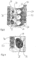
- FIG. 2 and 3 are perspective views of the outer mold with the omission of the mold half 12 shown schematically.
- the outer shape 20 has a cylinder jacket-like shape, wherein in Fig. 2 and 3 only one half is shown.
- Fig. 3 it can be seen that the outer shape 20 has a plurality of receptacles 26 into which inductors 22 are inserted.
- Fig. 2 shows the design of the outer shape 20 with the inductors 22 arranged in the receptacles 26.
- the inductors 22 are arranged at regular intervals in the outer shape.
- an induction generator 24 is provided (cf. Fig. 2 ), which is connected to the inductors 22.
- the induction generator 24 is provided here for controlling the inductors 22, whereby a magnetic field or an alternating magnetic field is generated by means of the inductors 22 due to the alternating current provided by the induction generator 24.
- the mold half 12 By means of the inductors 22 arranged on the mold half 12 designed as a tool mold (cf. Fig. 1 ) eddy currents are induced in the mold half 12, so that the power transferred into the mold half 12 is converted into heat by the eddy currents.
- the mold half 12 is made of steel, preferably of stainless steel.
- the mold half 12 can also have an outer shell made of steel or stainless steel, which is heated due to the induction heat.
- the inductors 22 can be connected in series or in parallel, the inductors 22 in this case with the induction generator 24 are connected.
- groups of serially connected inductors 22 can each be connected in parallel to another group of serially arranged inductors 22, which makes it possible to specifically heat individual segments in the mold half 12 as a result of the activation by the induction generator 24.
- FIG. 4 a perspective view of an inductor 22, which is arranged in the outer mold 20, is shown in detail.
- the inductor 22 here has an annular core 28 which is surrounded by an annular induction coil 30.
- the induction coil 30 is also connected to the induction generator 24.
- the induction coil 30 is also surrounded by an annular body 32, the annular body 32 and the core 28 having ferrite material or ferrites, whereby the core 28 and the annular body 32 are aligned as magnetic field alignment bodies, so that the alternating magnetic field generated by the induction coil 30 in the direction of the from the outer mold 20 encased mold half 12 is directed.
- FIG. 5 a schematic cross section through an inductor 22 according to a further embodiment is shown.
- the inductor 22 has a ferrite body 36, which has an inner cylindrical core 42, which surrounds a continuous hollow cylindrical opening 44 as a central hole, and an outer ring body 48, the inner cylindrical core 42 with the outer ring body 48 by means of a base plate 46 of the ferrite body 36 is connected.
- a fastening means such as a screw or the like, can be introduced into the opening 44 to fasten the inductor 22 in the outer shape.
- annular receptacle 50 of the ferrite body 36 is formed in the outer annular body 48, in which an annular coil 52 with windings is received or arranged.
- the annular receptacle 50 here has a U-shaped shape in cross section.
- the outer ring body 48 and the associated cylindrical core 42 of the inductor 22 are each formed on the side facing the tool shape with a, preferably circular arc-shaped curvature, so that the inductor 22 is complementary in shape to the, preferably curved, outer side of the tool shape, which the inductor 22 is facing, is formed.
- the ferrite body 36 can be made in one piece or in several pieces.
Landscapes
- Physics & Mathematics (AREA)
- Health & Medical Sciences (AREA)
- Engineering & Computer Science (AREA)
- Manufacturing & Machinery (AREA)
- Mechanical Engineering (AREA)
- Electromagnetism (AREA)
- Toxicology (AREA)
- Oral & Maxillofacial Surgery (AREA)
- Thermal Sciences (AREA)
- Moulds For Moulding Plastics Or The Like (AREA)
- Blow-Moulding Or Thermoforming Of Plastics Or The Like (AREA)
Claims (10)
- Dispositif de chauffage d'une machine de soufflage-étirage pour la fabrication de corps creux en matière plastique avec un moule-outillage (12) présentant une cavité (14) et un moule extérieur (20) pour le moule-outillage (12), entourant le moule-outillage (12), le moule extérieur (20) présentant au moins un ou plusieurs inducteurs, lesdits au moins un inducteurs (22) ou les inducteurs (22) étant reliés à un générateur inducteur (24) pour la commande du ou des inducteurs (22), caractérisé en ce que ledit au moins un inducteur ou lesdits inducteurs (22) ont chacun une bobine annulaire (30), la bobine (30) étant disposée entre un noyau (28) et un corps annulaire (32), et le noyau (28) et le corps annulaire (32) sont des corps (28, 32) d'alignement de champ magnétique qui sont constitués d'un matériau en ferrite et qui présentent une forme annulaire ou tubulaire, le noyau (28) et le corps annulaire (32) étant reliés par une plaque de base (46) en forme de disque ou de plaque en tant qu'autre corps d'alignement du champ magnétique.
- Dispositif de chauffage selon la revendication 1, caractérisé en ce qu'une pluralité d'inducteurs (22) sont connectés en série ou en parallèle.
- Dispositif de chauffage selon la revendication 1, caractérisé en ce que plusieurs groupes d'inducteurs (22) connectés en série sont connectés en parallèle.
- Dispositif de chauffage selon l'une des revendications 1 à 3, caractérisé en ce que les inducteurs (22) sont disposés à intervalles réguliers les uns par rapport aux autres dans des réceptacles (26) du moule extérieur (20) pour les inducteurs (22).
- Dispositif de chauffage selon l'une des revendications 1 à 4, caractérisé en ce que le moule-outillage (12) et le moule extérieur (20) pour le moule-outillage (12) sont disposés avec liaison par coopération de formes ou le moule-outillage (12) et le moule extérieur (20) pour le moule-outillage (12) sont espacés l'un de l'autre à une distance constante, la distance entre le moule-outillage (12) et le moule extérieur (20) étant notamment comprise entre 0,1 cm et 1,0 cm, en particulier entre 0,1 cm et 0,5 cm.
- Dispositif de chauffage selon l'une des revendications 1 à 5, caractérisé en ce que le moule-outillage (12) est en acier, notamment en acier inoxydable, ou en ce que le moule-outillage (12) présente une coque extérieure en acier, en particulier en acier inoxydable.
- Dispositif de chauffage selon l'une des revendications 1 à 6, caractérisé en ce que les inducteurs (22) sont commandés ou aptes à être commandés individuellement au moyen du générateur inducteur et/ou en ce que plusieurs inducteurs (22) sont commandés ou aptes à être commandés simultanément au moyen du générateur inducteur et/ou en ce que les inducteurs (22) sont commandés ou aptes à être commandés au moyen du générateur inducteur de telle sorte qu'un gradient de température prédéterminé est formé ou apte à être formé le long de l'étendue longitudinale et / ou dans la direction circonférentielle du moule-outillage (12).
- Machine de soufflage-étirage pour la production de corps creux en matière plastique avec un dispositif de chauffage selon l'une des revendications 1 à 7.
- Procédé pour faire fonctionner une machine de soufflage-étirage avec un dispositif de chauffage selon l'une des revendications 1 à 7.
- Utilisation d'un dispositif de chauffage selon l'une des revendications 1 à 7 dans une machine de soufflage-étirage pour la production d'articles creux en matière plastique.
Priority Applications (1)
| Application Number | Priority Date | Filing Date | Title |
|---|---|---|---|
| EP18169449.8A EP3560671B1 (fr) | 2018-04-26 | 2018-04-26 | Dispositif de chauffage d'une machine de soufflage-étirage |
Applications Claiming Priority (1)
| Application Number | Priority Date | Filing Date | Title |
|---|---|---|---|
| EP18169449.8A EP3560671B1 (fr) | 2018-04-26 | 2018-04-26 | Dispositif de chauffage d'une machine de soufflage-étirage |
Publications (3)
| Publication Number | Publication Date |
|---|---|
| EP3560671A1 EP3560671A1 (fr) | 2019-10-30 |
| EP3560671A8 EP3560671A8 (fr) | 2019-12-25 |
| EP3560671B1 true EP3560671B1 (fr) | 2020-12-30 |
Family
ID=62067458
Family Applications (1)
| Application Number | Title | Priority Date | Filing Date |
|---|---|---|---|
| EP18169449.8A Not-in-force EP3560671B1 (fr) | 2018-04-26 | 2018-04-26 | Dispositif de chauffage d'une machine de soufflage-étirage |
Country Status (1)
| Country | Link |
|---|---|
| EP (1) | EP3560671B1 (fr) |
Family Cites Families (7)
| Publication number | Priority date | Publication date | Assignee | Title |
|---|---|---|---|---|
| DE19802855A1 (de) * | 1998-01-26 | 1998-07-09 | Protoned Bv | Verfahren und Formwerkzeug zur Herstellung von Kunststoff-Formteilen |
| FR2816237B1 (fr) * | 2000-11-08 | 2003-09-19 | Roctool | Moules pour la transformation des matieres plastiques et composites et procede de transformation associe |
| FR2867939B1 (fr) * | 2004-03-18 | 2007-08-10 | Roctool | Procede pour chauffer des materiaux en vue de produire des objets et dispositif mettant en oeuvre de procede |
| JP5513079B2 (ja) * | 2009-11-06 | 2014-06-04 | 三菱レイヨン株式会社 | 金型及び熱可塑性樹脂系繊維強化複合材料成形品の製造方法 |
| US9820339B2 (en) * | 2011-09-29 | 2017-11-14 | The Boeing Company | Induction heating using induction coils in series-parallel circuits |
| FR3051136A1 (fr) * | 2016-05-10 | 2017-11-17 | Roctool | Procede et dispositif pour le chauffage d’un moule |
| DE102016113875B4 (de) | 2016-07-27 | 2019-07-18 | Khs Corpoplast Gmbh | Heizvorrichtung für eine Blasmaschine mit Förderkette für einen zweireihigen Transport der Vorformlinge |
-
2018
- 2018-04-26 EP EP18169449.8A patent/EP3560671B1/fr not_active Not-in-force
Non-Patent Citations (1)
| Title |
|---|
| None * |
Also Published As
| Publication number | Publication date |
|---|---|
| EP3560671A8 (fr) | 2019-12-25 |
| EP3560671A1 (fr) | 2019-10-30 |
Similar Documents
| Publication | Publication Date | Title |
|---|---|---|
| DE69910823T2 (de) | Spritzgiesskühlkern mit spiralnuten | |
| EP3251196B1 (fr) | Dispositif autocollant de fermeture d'encoche pour une machine électrique | |
| DE102014004157B4 (de) | Verfahren zur Herstellung von Lasteinleitungs-Flanschen an faserverstärkten Hohlprofilen mit thermoplastischer Matrix | |
| EP2823196B1 (fr) | Douille élastique et tenon à ressort | |
| EP2208597B1 (fr) | Unité de résonateur, procédé d'expansion et dispositif de chauffage de récipients | |
| EP3024630B1 (fr) | Machine à vis et procédé de chauffage de vis par induction dans une zone de chauffage | |
| DE102011108157A1 (de) | Formwerkzeug und Verfahren zur Herstellung von Faserverbundkunststoff-Bauteilen | |
| EP3560671B1 (fr) | Dispositif de chauffage d'une machine de soufflage-étirage | |
| WO2017055260A1 (fr) | Machine à vis sans fin et procédé pour préparer une matière plastique | |
| DE102011053867B4 (de) | Spritzgießwerkzeug mit Induktor für die Herstellung von Kunststoffformteilen | |
| EP3952076A1 (fr) | Procédé d'imprégnation par dégouttage du stator ou de l'ancrage d'une machine électrique | |
| DE102019002234A1 (de) | Imprägniervorrichtung zur Träufelimprägnierung eines Strators einer Elektromaschine | |
| EP3810398B1 (fr) | Dispositif de production de recipients par moulage par soufflage | |
| EP1065037B1 (fr) | Procédé et dispositif pour le chauffage de moules d'injection | |
| DE102017011048B4 (de) | Vorrichtung und induktives Härteverfahren zum induktiven Härten von metallischen Werkstücken sowie Verwendung der Vorrichtung | |
| DE698534C (fr) | ||
| DE102012003174A1 (de) | Verfahren und Vorrichtung zum Herstellen eines Hohlprofils mit Abschnitten unterschiedlicher Wandstärke | |
| DE19637844A1 (de) | Beheizbare Form | |
| DE1158698B (de) | Verfahren und Vorrichtung zum Herstellen von Quetschtuben aus thermoplastischem Werkstoff | |
| EP3842208A1 (fr) | Utilisation d'un dispositif de chauffage inductif d'un élément d'insertion, de préférence métallique, électro-conducteur, en tant que composant d'un objet moulé par injection | |
| DE102013010304A1 (de) | Verfahren zum Herstellen eines faserverstärkten Kunststoffbauteils | |
| WO1993017818A1 (fr) | Procede et dispositif pour chauffer par induction au moins une piece d'insertion pour une piece coulee composite | |
| DE102022134393A1 (de) | Aktiv gekühlter Feldformer mit dauerbelastbar angeschlossenen Kühlmittelleitungen | |
| DE102018202270A1 (de) | Induktionsvorrichtung und System aus Wälzlagerkomponente und Induktionsvorrichtung | |
| AT217207B (de) | Verfahren zur Herstellung von Rohrabzweigungen und Vorrichtung zur Ausübung desselben |
Legal Events
| Date | Code | Title | Description |
|---|---|---|---|
| PUAI | Public reference made under article 153(3) epc to a published international application that has entered the european phase |
Free format text: ORIGINAL CODE: 0009012 |
|
| STAA | Information on the status of an ep patent application or granted ep patent |
Free format text: STATUS: THE APPLICATION HAS BEEN PUBLISHED |
|
| AK | Designated contracting states |
Kind code of ref document: A1 Designated state(s): AL AT BE BG CH CY CZ DE DK EE ES FI FR GB GR HR HU IE IS IT LI LT LU LV MC MK MT NL NO PL PT RO RS SE SI SK SM TR |
|
| AX | Request for extension of the european patent |
Extension state: BA ME |
|
| RAP1 | Party data changed (applicant data changed or rights of an application transferred) |
Owner name: KENDRION KUHNKE AUTOMATION GMBH |
|
| STAA | Information on the status of an ep patent application or granted ep patent |
Free format text: STATUS: REQUEST FOR EXAMINATION WAS MADE |
|
| 17P | Request for examination filed |
Effective date: 20200424 |
|
| RBV | Designated contracting states (corrected) |
Designated state(s): AL AT BE BG CH CY CZ DE DK EE ES FI FR GB GR HR HU IE IS IT LI LT LU LV MC MK MT NL NO PL PT RO RS SE SI SK SM TR |
|
| GRAP | Despatch of communication of intention to grant a patent |
Free format text: ORIGINAL CODE: EPIDOSNIGR1 |
|
| STAA | Information on the status of an ep patent application or granted ep patent |
Free format text: STATUS: GRANT OF PATENT IS INTENDED |
|
| RIC1 | Information provided on ipc code assigned before grant |
Ipc: B29C 49/48 20060101ALI20200930BHEP Ipc: B29C 49/06 20060101ALN20200930BHEP Ipc: B29K 67/00 20060101ALN20200930BHEP Ipc: B29C 35/08 20060101AFI20200930BHEP |
|
| RIC1 | Information provided on ipc code assigned before grant |
Ipc: B29C 49/06 20060101ALN20201014BHEP Ipc: B29C 49/48 20060101ALI20201014BHEP Ipc: B29K 67/00 20060101ALN20201014BHEP Ipc: B29C 35/08 20060101AFI20201014BHEP |
|
| GRAS | Grant fee paid |
Free format text: ORIGINAL CODE: EPIDOSNIGR3 |
|
| INTG | Intention to grant announced |
Effective date: 20201030 |
|
| GRAA | (expected) grant |
Free format text: ORIGINAL CODE: 0009210 |
|
| STAA | Information on the status of an ep patent application or granted ep patent |
Free format text: STATUS: THE PATENT HAS BEEN GRANTED |
|
| AK | Designated contracting states |
Kind code of ref document: B1 Designated state(s): AL AT BE BG CH CY CZ DE DK EE ES FI FR GB GR HR HU IE IS IT LI LT LU LV MC MK MT NL NO PL PT RO RS SE SI SK SM TR |
|
| REG | Reference to a national code |
Ref country code: GB Ref legal event code: FG4D Free format text: NOT ENGLISH |
|
| REG | Reference to a national code |
Ref country code: AT Ref legal event code: REF Ref document number: 1349477 Country of ref document: AT Kind code of ref document: T Effective date: 20210115 |
|
| REG | Reference to a national code |
Ref country code: DE Ref legal event code: R096 Ref document number: 502018003430 Country of ref document: DE |
|
| REG | Reference to a national code |
Ref country code: IE Ref legal event code: FG4D Free format text: LANGUAGE OF EP DOCUMENT: GERMAN |
|
| PG25 | Lapsed in a contracting state [announced via postgrant information from national office to epo] |
Ref country code: RS Free format text: LAPSE BECAUSE OF FAILURE TO SUBMIT A TRANSLATION OF THE DESCRIPTION OR TO PAY THE FEE WITHIN THE PRESCRIBED TIME-LIMIT Effective date: 20201230 Ref country code: FI Free format text: LAPSE BECAUSE OF FAILURE TO SUBMIT A TRANSLATION OF THE DESCRIPTION OR TO PAY THE FEE WITHIN THE PRESCRIBED TIME-LIMIT Effective date: 20201230 Ref country code: GR Free format text: LAPSE BECAUSE OF FAILURE TO SUBMIT A TRANSLATION OF THE DESCRIPTION OR TO PAY THE FEE WITHIN THE PRESCRIBED TIME-LIMIT Effective date: 20210331 Ref country code: NO Free format text: LAPSE BECAUSE OF FAILURE TO SUBMIT A TRANSLATION OF THE DESCRIPTION OR TO PAY THE FEE WITHIN THE PRESCRIBED TIME-LIMIT Effective date: 20210330 |
|
| PG25 | Lapsed in a contracting state [announced via postgrant information from national office to epo] |
Ref country code: BG Free format text: LAPSE BECAUSE OF FAILURE TO SUBMIT A TRANSLATION OF THE DESCRIPTION OR TO PAY THE FEE WITHIN THE PRESCRIBED TIME-LIMIT Effective date: 20210330 Ref country code: SE Free format text: LAPSE BECAUSE OF FAILURE TO SUBMIT A TRANSLATION OF THE DESCRIPTION OR TO PAY THE FEE WITHIN THE PRESCRIBED TIME-LIMIT Effective date: 20201230 Ref country code: LV Free format text: LAPSE BECAUSE OF FAILURE TO SUBMIT A TRANSLATION OF THE DESCRIPTION OR TO PAY THE FEE WITHIN THE PRESCRIBED TIME-LIMIT Effective date: 20201230 |
|
| REG | Reference to a national code |
Ref country code: NL Ref legal event code: MP Effective date: 20201230 |
|
| PG25 | Lapsed in a contracting state [announced via postgrant information from national office to epo] |
Ref country code: HR Free format text: LAPSE BECAUSE OF FAILURE TO SUBMIT A TRANSLATION OF THE DESCRIPTION OR TO PAY THE FEE WITHIN THE PRESCRIBED TIME-LIMIT Effective date: 20201230 |
|
| REG | Reference to a national code |
Ref country code: LT Ref legal event code: MG9D |
|
| PG25 | Lapsed in a contracting state [announced via postgrant information from national office to epo] |
Ref country code: LT Free format text: LAPSE BECAUSE OF FAILURE TO SUBMIT A TRANSLATION OF THE DESCRIPTION OR TO PAY THE FEE WITHIN THE PRESCRIBED TIME-LIMIT Effective date: 20201230 Ref country code: PT Free format text: LAPSE BECAUSE OF FAILURE TO SUBMIT A TRANSLATION OF THE DESCRIPTION OR TO PAY THE FEE WITHIN THE PRESCRIBED TIME-LIMIT Effective date: 20210430 Ref country code: RO Free format text: LAPSE BECAUSE OF FAILURE TO SUBMIT A TRANSLATION OF THE DESCRIPTION OR TO PAY THE FEE WITHIN THE PRESCRIBED TIME-LIMIT Effective date: 20201230 Ref country code: SK Free format text: LAPSE BECAUSE OF FAILURE TO SUBMIT A TRANSLATION OF THE DESCRIPTION OR TO PAY THE FEE WITHIN THE PRESCRIBED TIME-LIMIT Effective date: 20201230 Ref country code: EE Free format text: LAPSE BECAUSE OF FAILURE TO SUBMIT A TRANSLATION OF THE DESCRIPTION OR TO PAY THE FEE WITHIN THE PRESCRIBED TIME-LIMIT Effective date: 20201230 Ref country code: CZ Free format text: LAPSE BECAUSE OF FAILURE TO SUBMIT A TRANSLATION OF THE DESCRIPTION OR TO PAY THE FEE WITHIN THE PRESCRIBED TIME-LIMIT Effective date: 20201230 |
|
| PG25 | Lapsed in a contracting state [announced via postgrant information from national office to epo] |
Ref country code: PL Free format text: LAPSE BECAUSE OF FAILURE TO SUBMIT A TRANSLATION OF THE DESCRIPTION OR TO PAY THE FEE WITHIN THE PRESCRIBED TIME-LIMIT Effective date: 20201230 |
|
| PG25 | Lapsed in a contracting state [announced via postgrant information from national office to epo] |
Ref country code: IS Free format text: LAPSE BECAUSE OF FAILURE TO SUBMIT A TRANSLATION OF THE DESCRIPTION OR TO PAY THE FEE WITHIN THE PRESCRIBED TIME-LIMIT Effective date: 20210430 |
|
| REG | Reference to a national code |
Ref country code: DE Ref legal event code: R097 Ref document number: 502018003430 Country of ref document: DE |
|
| PG25 | Lapsed in a contracting state [announced via postgrant information from national office to epo] |
Ref country code: AL Free format text: LAPSE BECAUSE OF FAILURE TO SUBMIT A TRANSLATION OF THE DESCRIPTION OR TO PAY THE FEE WITHIN THE PRESCRIBED TIME-LIMIT Effective date: 20201230 Ref country code: IT Free format text: LAPSE BECAUSE OF FAILURE TO SUBMIT A TRANSLATION OF THE DESCRIPTION OR TO PAY THE FEE WITHIN THE PRESCRIBED TIME-LIMIT Effective date: 20201230 |
|
| PLBE | No opposition filed within time limit |
Free format text: ORIGINAL CODE: 0009261 |
|
| STAA | Information on the status of an ep patent application or granted ep patent |
Free format text: STATUS: NO OPPOSITION FILED WITHIN TIME LIMIT |
|
| PG25 | Lapsed in a contracting state [announced via postgrant information from national office to epo] |
Ref country code: DK Free format text: LAPSE BECAUSE OF FAILURE TO SUBMIT A TRANSLATION OF THE DESCRIPTION OR TO PAY THE FEE WITHIN THE PRESCRIBED TIME-LIMIT Effective date: 20201230 Ref country code: MC Free format text: LAPSE BECAUSE OF FAILURE TO SUBMIT A TRANSLATION OF THE DESCRIPTION OR TO PAY THE FEE WITHIN THE PRESCRIBED TIME-LIMIT Effective date: 20201230 |
|
| 26N | No opposition filed |
Effective date: 20211001 |
|
| PG25 | Lapsed in a contracting state [announced via postgrant information from national office to epo] |
Ref country code: LU Free format text: LAPSE BECAUSE OF NON-PAYMENT OF DUE FEES Effective date: 20210426 |
|
| REG | Reference to a national code |
Ref country code: BE Ref legal event code: MM Effective date: 20210430 |
|
| PG25 | Lapsed in a contracting state [announced via postgrant information from national office to epo] |
Ref country code: LI Free format text: LAPSE BECAUSE OF NON-PAYMENT OF DUE FEES Effective date: 20210430 Ref country code: CH Free format text: LAPSE BECAUSE OF NON-PAYMENT OF DUE FEES Effective date: 20210430 Ref country code: ES Free format text: LAPSE BECAUSE OF FAILURE TO SUBMIT A TRANSLATION OF THE DESCRIPTION OR TO PAY THE FEE WITHIN THE PRESCRIBED TIME-LIMIT Effective date: 20201230 |
|
| PG25 | Lapsed in a contracting state [announced via postgrant information from national office to epo] |
Ref country code: SI Free format text: LAPSE BECAUSE OF FAILURE TO SUBMIT A TRANSLATION OF THE DESCRIPTION OR TO PAY THE FEE WITHIN THE PRESCRIBED TIME-LIMIT Effective date: 20201230 |
|
| PG25 | Lapsed in a contracting state [announced via postgrant information from national office to epo] |
Ref country code: IE Free format text: LAPSE BECAUSE OF NON-PAYMENT OF DUE FEES Effective date: 20210426 |
|
| PG25 | Lapsed in a contracting state [announced via postgrant information from national office to epo] |
Ref country code: IS Free format text: LAPSE BECAUSE OF FAILURE TO SUBMIT A TRANSLATION OF THE DESCRIPTION OR TO PAY THE FEE WITHIN THE PRESCRIBED TIME-LIMIT Effective date: 20210430 |
|
| PG25 | Lapsed in a contracting state [announced via postgrant information from national office to epo] |
Ref country code: BE Free format text: LAPSE BECAUSE OF NON-PAYMENT OF DUE FEES Effective date: 20210430 |
|
| GBPC | Gb: european patent ceased through non-payment of renewal fee |
Effective date: 20220426 |
|
| PG25 | Lapsed in a contracting state [announced via postgrant information from national office to epo] |
Ref country code: GB Free format text: LAPSE BECAUSE OF NON-PAYMENT OF DUE FEES Effective date: 20220426 |
|
| P01 | Opt-out of the competence of the unified patent court (upc) registered |
Effective date: 20230512 |
|
| PG25 | Lapsed in a contracting state [announced via postgrant information from national office to epo] |
Ref country code: NL Free format text: LAPSE BECAUSE OF NON-PAYMENT OF DUE FEES Effective date: 20201230 Ref country code: CY Free format text: LAPSE BECAUSE OF FAILURE TO SUBMIT A TRANSLATION OF THE DESCRIPTION OR TO PAY THE FEE WITHIN THE PRESCRIBED TIME-LIMIT Effective date: 20201230 |
|
| PG25 | Lapsed in a contracting state [announced via postgrant information from national office to epo] |
Ref country code: SM Free format text: LAPSE BECAUSE OF FAILURE TO SUBMIT A TRANSLATION OF THE DESCRIPTION OR TO PAY THE FEE WITHIN THE PRESCRIBED TIME-LIMIT Effective date: 20201230 Ref country code: HU Free format text: LAPSE BECAUSE OF FAILURE TO SUBMIT A TRANSLATION OF THE DESCRIPTION OR TO PAY THE FEE WITHIN THE PRESCRIBED TIME-LIMIT; INVALID AB INITIO Effective date: 20180426 |
|
| PG25 | Lapsed in a contracting state [announced via postgrant information from national office to epo] |
Ref country code: MK Free format text: LAPSE BECAUSE OF FAILURE TO SUBMIT A TRANSLATION OF THE DESCRIPTION OR TO PAY THE FEE WITHIN THE PRESCRIBED TIME-LIMIT Effective date: 20201230 |
|
| REG | Reference to a national code |
Ref country code: AT Ref legal event code: MM01 Ref document number: 1349477 Country of ref document: AT Kind code of ref document: T Effective date: 20230426 |
|
| PGFP | Annual fee paid to national office [announced via postgrant information from national office to epo] |
Ref country code: DE Payment date: 20240418 Year of fee payment: 7 |
|
| PG25 | Lapsed in a contracting state [announced via postgrant information from national office to epo] |
Ref country code: AT Free format text: LAPSE BECAUSE OF NON-PAYMENT OF DUE FEES Effective date: 20230426 |
|
| PG25 | Lapsed in a contracting state [announced via postgrant information from national office to epo] |
Ref country code: AT Free format text: LAPSE BECAUSE OF NON-PAYMENT OF DUE FEES Effective date: 20230426 |
|
| PGFP | Annual fee paid to national office [announced via postgrant information from national office to epo] |
Ref country code: FR Payment date: 20240423 Year of fee payment: 7 |
|
| PG25 | Lapsed in a contracting state [announced via postgrant information from national office to epo] |
Ref country code: MT Free format text: LAPSE BECAUSE OF FAILURE TO SUBMIT A TRANSLATION OF THE DESCRIPTION OR TO PAY THE FEE WITHIN THE PRESCRIBED TIME-LIMIT Effective date: 20201230 |
|
| REG | Reference to a national code |
Ref country code: DE Ref legal event code: R119 Ref document number: 502018003430 Country of ref document: DE |
|
| PG25 | Lapsed in a contracting state [announced via postgrant information from national office to epo] |
Ref country code: TR Free format text: LAPSE BECAUSE OF FAILURE TO SUBMIT A TRANSLATION OF THE DESCRIPTION OR TO PAY THE FEE WITHIN THE PRESCRIBED TIME-LIMIT Effective date: 20201230 |
|
| PG25 | Lapsed in a contracting state [announced via postgrant information from national office to epo] |
Ref country code: DE Free format text: LAPSE BECAUSE OF NON-PAYMENT OF DUE FEES Effective date: 20251104 |
|
| PG25 | Lapsed in a contracting state [announced via postgrant information from national office to epo] |
Ref country code: FR Free format text: LAPSE BECAUSE OF NON-PAYMENT OF DUE FEES Effective date: 20250430 |
|
| PGFP | Annual fee paid to national office [announced via postgrant information from national office to epo] |
Ref country code: AT Payment date: 20260410 Year of fee payment: 5 |