EP3560875A2 - Régulateur de vitesse et système d'ascenseur - Google Patents
Régulateur de vitesse et système d'ascenseur Download PDFInfo
- Publication number
- EP3560875A2 EP3560875A2 EP19169970.1A EP19169970A EP3560875A2 EP 3560875 A2 EP3560875 A2 EP 3560875A2 EP 19169970 A EP19169970 A EP 19169970A EP 3560875 A2 EP3560875 A2 EP 3560875A2
- Authority
- EP
- European Patent Office
- Prior art keywords
- speed
- speed governor
- governor assembly
- sheave
- core ring
- Prior art date
- Legal status (The legal status is an assumption and is not a legal conclusion. Google has not performed a legal analysis and makes no representation as to the accuracy of the status listed.)
- Granted
Links
Images



Classifications
-
- B—PERFORMING OPERATIONS; TRANSPORTING
- B66—HOISTING; LIFTING; HAULING
- B66B—ELEVATORS; ESCALATORS OR MOVING WALKWAYS
- B66B1/00—Control systems of elevators in general
- B66B1/24—Control systems with regulation, i.e. with retroactive action, for influencing travelling speed, acceleration, or deceleration
- B66B1/28—Control systems with regulation, i.e. with retroactive action, for influencing travelling speed, acceleration, or deceleration electrical
- B66B1/32—Control systems with regulation, i.e. with retroactive action, for influencing travelling speed, acceleration, or deceleration electrical effective on braking devices, e.g. acting on electrically controlled brakes
-
- B—PERFORMING OPERATIONS; TRANSPORTING
- B66—HOISTING; LIFTING; HAULING
- B66B—ELEVATORS; ESCALATORS OR MOVING WALKWAYS
- B66B1/00—Control systems of elevators in general
- B66B1/34—Details, e.g. call counting devices, data transmission from car to control system, devices giving information to the control system
- B66B1/3415—Control system configuration and the data transmission or communication within the control system
- B66B1/3423—Control system configuration, i.e. lay-out
- B66B1/343—Fault-tolerant or redundant control system configuration
-
- B—PERFORMING OPERATIONS; TRANSPORTING
- B66—HOISTING; LIFTING; HAULING
- B66B—ELEVATORS; ESCALATORS OR MOVING WALKWAYS
- B66B5/00—Applications of checking, fault-correcting, or safety devices in elevators
- B66B5/02—Applications of checking, fault-correcting, or safety devices in elevators responsive to abnormal operating conditions
- B66B5/04—Applications of checking, fault-correcting, or safety devices in elevators responsive to abnormal operating conditions for detecting excessive speed
- B66B5/044—Mechanical overspeed governors
-
- B—PERFORMING OPERATIONS; TRANSPORTING
- B66—HOISTING; LIFTING; HAULING
- B66B—ELEVATORS; ESCALATORS OR MOVING WALKWAYS
- B66B5/00—Applications of checking, fault-correcting, or safety devices in elevators
- B66B5/02—Applications of checking, fault-correcting, or safety devices in elevators responsive to abnormal operating conditions
- B66B5/04—Applications of checking, fault-correcting, or safety devices in elevators responsive to abnormal operating conditions for detecting excessive speed
- B66B5/06—Applications of checking, fault-correcting, or safety devices in elevators responsive to abnormal operating conditions for detecting excessive speed electrical
-
- B—PERFORMING OPERATIONS; TRANSPORTING
- B66—HOISTING; LIFTING; HAULING
- B66B—ELEVATORS; ESCALATORS OR MOVING WALKWAYS
- B66B7/00—Other common features of elevators
- B66B7/06—Arrangements of ropes or cables
-
- B—PERFORMING OPERATIONS; TRANSPORTING
- B66—HOISTING; LIFTING; HAULING
- B66D—CAPSTANS; WINCHES; TACKLES, e.g. PULLEY BLOCKS; HOISTS
- B66D1/00—Rope, cable, or chain winding mechanisms; Capstans
- B66D1/54—Safety gear
- B66D1/56—Adaptations of limit switches
Definitions
- the present invention relates to the field of elevator safety and, more particularly, to a speed governor assembly for an elevator and an elevator having such a speed governor assembly.
- a speed governor assembly is disclosed in U.S. Patent No. US 2013/0098711A1, issued to Aguado et al, published on April 25, 2013 , in which the speed governor assembly includes a centrifugal mechanism gradually deployed as a rotational speed of a sheave increases. When the sheave reaches a first speed, the outer side of the centrifugal mechanism pushes an overspeed protection switch, thereby braking the elevator through an electrical mechanism.
- the centrifugal mechanism will drive a core ring in the inner side thereof, thereby triggering a mechanical brake device.
- the first speed and the second speed are related to the basic running speed of the elevator, and the ratio of the first speed to the second speed is required to meet national standards, for example, less than a specific value, such as 90%.
- the overspeed protection switch is set farther, the first speed can be increased to widen the difference between the first speed and the basic running speed, thereby reducing the possibility of false triggering.
- this may result in that the overspeed protection switch is not triggered or triggered later than the mechanical brake device, which may cause damage to related components in the elevator system and does not meet relevant national safety standards.
- the objective of the present invention is to solve or at least alleviate the problems existing in the prior art; according to some features, it is an objective of the present invention to ensure that the electrical brake device of the speed governor assembly is triggered not later than the mechanical brake device.
- a speed governor assembly including:
- the centrifuge mechanism when the sheave reaches a first speed, the centrifuge mechanism is deployed to a degree such that it can contact and trigger the overspeed protection switch.
- the first distance is set such that a ratio of the first speed to the second speed is in a range of 0.9-1.0 (excluding 1.0) preferably, in a range of 0.95-1.0 (excluding 1.0).
- the triggering arm is directly connected to the core ring.
- the core ring is connected to a rocker arm, and the triggering arm is connected to the rocker arm.
- the core ring drives the rocker arm to rotate and triggers a mechanical brake device when the sheave reaches the second speed.
- the rocker arm has a first end and a second end, the first end of the rocker arm is connected to the core ring, and the second end of the rocker arm is connected to a safety gear pull rod.
- the triggering arm is connected between the first end and the second end of the rocker arm and extends upwardly.
- the triggering arm is in a shape of plate or column, and the triggering arm has a proximal end for connection with the rocker arm or the core ring and a distal end for triggering the overspeed protection switch.
- the distal end of the triggering arm has an axial extension portion that is aligned with a contact end of the overspeed protection switch.
- the proximal end of the triggering arm is connected to the rocker arm or the core ring through a plurality of bolts.
- the triggering arm and the overspeed protection switch are on the same side of the rotation axis of the sheave.
- the overspeed protection switch is above the triggering arm.
- the centrifugation mechanism includes a plurality of centrifugal block supports each carrying a centrifugal block, a plurality of connecting rods connected between the plurality of centrifugal block supports and a retaining mechanism holding the plurality of centrifugal block supports together.
- the centrifugal block support when the sheave reaches a first speed, the centrifugal block support is deployed to a degree such that the overspeed protection switch can be triggered.
- a roller inside the plurality of connecting rods of the centrifugal mechanism engages with the core ring and drives the core ring to rotate.
- the retaining mechanism is a spring device or a magnetic device.
- an elevator system is provided.
- the elevator system is configured with the speed governor assembly described in various embodiments.
- the speed governor assembly is mounted to an elevator car.
- a basic running speed of the car in the elevator system is less than 1.0 m/s.
- the speed governor assembly and the elevator system according to the present invention ensure that the electrical brake device of the elevator system is triggered not later than the mechanical brake device and eliminate the possibility that electrical action speed of the speed governor does not meet the requirements of the relevant national standards.
- top, bottom, left, right, front, back, front, rear, top, bottom, etc. mentioned or may be mentioned in this specification are defined with respect to the configurations shown in the respective drawings. They are relative concepts, so they may change accordingly depending on their location and usage. Therefore, these or other orientation terms should not be interpreted as restrictive terms.
- FIG. 1 an elevator system having a car mounted speed governor assembly is illustrated. It should be understood that although various embodiments of the present invention are described with respect to a car mounted speed governor assembly, the core ring assembly of the present invention can be used with various types of speed governors, not limited to those shown in the various views or embodiments.
- a car 92 is shown in Fig. 1 with a speed governor assembly 98 mounted thereon.
- a typical speed governor assembly 98 can be found, for example, in the type described in U.S. Patent Publication No. US20130098711 A1 to Otis Elevator Company, published on April 25 2013, which is hereby incorporated by reference in its entirety.
- the speed governor assembly 98 includes a guide pulley 95 and a speed governor sheave 94.
- a rope suspended from a hoistway top 91 winds around the guide pulley 95 and the speed governor sheave 94.
- the rope has a speed governor upstream rope portion 96 and a speed governor downstream rope portion 97, and the length of the speed governor upstream rope portion 96 and the length of the speed governor downstream rope portion 97 constantly change during ascending or descending processes of the car.
- the bottom end of the speed governor downstream rope portion 97 is suspended with a weight 93 or connected to a pulling device that provides tension for the rope.
- the guide pulley 95 and the speed governor sheave 94 will rotate due to friction with the rope.
- the rotation linear speed of the pitch circle of the speed governor sheave 94 is the same as the running speed of the car.
- the centrifugal mechanism associated with the speed governor sheave 94 triggers the electric brake device since the sheave speed exceeds the first speed, cuts off the power supply of the elevator drive motor, and stops the drive sprocket.
- the centrifugal mechanism triggers the mechanical brake device to brake the elevator car by friction with the guide rail.
- FIGs. 2 , 3 and 4 perspective and front views, viewed at different angles, of the speed governor assembly when the sheave is not overspeeded are shown. It should be understood that only portions of the speed governor assembly that are closely related to the present invention are shown in the drawings, and that some of the components are omitted for clarity.
- the speed governor assembly includes: a frame 10, for example mounted to an elevator car; a sheave 3 rotatably arranged on a shaft and having a rope groove 31 in which the rope can be wound; a centrifugal mechanism 4 mounted on the sheave and rotated together with the sheave; an overspeed protection switch 20 at a first distance from a radial outer side of the centrifugal mechanism; a core ring 5 coaxial with the sheave and disposed in a radial side of the centrifugal mechanism 4; and a triggering arm 7 rotating together with the core ring 5; wherein the centrifugal mechanism 4 engages with the core ring 5 and drives the core ring 5 and the triggering arm 7 to rotate when the sheave 3 reaches the second speed, and the rotation of the triggering arm 7 can contact and trigger the overspeed protection switch 20.
- the present invention provides a triggering arm 7 associated with the core ring 5, ensuring that the overspeed protection switch 20 will be triggered not later than the mechanical brake device when the sheave reaches the second speed.
- the centrifuge mechanism 4 is deployed to a degree such that it can contact and trigger the overspeed protection switch 20, and the first speed is less than the second speed.
- the speed governor assembly is also configured with a remote triggering device 8 for actively triggering the speed governor assembly.
- the second speed which may also be referred to as a mechanical brake device triggering speed limit, is determined by the centrifugal mechanism 4 itself and is not adjustable.
- the first speed which may also be referred to as an overspeed protection switch triggering speed limit, is the speed at which the centrifugal mechanism 4 is deployed to push the overspeed protection switch 2. Since the centrifugal mechanism 4 is gradually deployed as the speed of the sheave 3 is increased, the degree of deployment depends on the speed of the sheave 3. The higher the speed of the sheave 3 is, the farther the centrifugal mechanism 4 is deployed. Therefore, the first speed can be adjusted by setting the first distance from the overspeed protection switch 20 to the centrifugal mechanism 4.
- the first distance may be set such that the ratio of the first speed to the second speed is above 0.8, such as 0.8-0.9, preferably above 0.85, such as in the range of 0.85 to 0.9.
- the first distance may be set such that the ratio of the first speed to the second speed is above 0.9, such as in the range of 0.9-1.0 (excluding 1.0), more preferably, above 0.95, such as in the range of 0.95-1.0 (excluding 1.0).
- the centrifugal mechanism 4 is not fully rounded during deployment, and there are points in the peripheral contour of the centrifugal mechanism 4 that are farther or closer from the center of rotation. Although when the sheave reaches the first speed, the farther point on the centrifugal mechanism 4 can reach and trigger the overspeed protection switch 20, while those closer points, when being at the same angular position as the overspeed protection switch 20, may not reach the overspeed protection switch 20, thereby failing in triggering the overspeed protection switch 20.
- the overspeed protection switch 20 can be set as far as possible.
- the first speed can be increased as much as possible under the condition that the standard is met (for example, the standard of the first speed/the second speed being larger than 0.9), thereby increasing the difference between the first speed and the basic running speed, reducing the risk of the overspeed protection switch 20 being falsely triggered, and eliminating the possibility that the electrical action speed of the speed governor does not meet the requirements of the relevant national standards.
- the standard for example, the standard of the first speed/the second speed being larger than 0.9
- the core ring 5 is also associated with a mechanical brake device, such that with the rotation of the core ring 5, the mechanical brake device is caused to rub against the elevator rail, thereby braking the car.
- the core ring 5 causes a rocker arm 6 to rotate and trigger the mechanical brake device.
- the triggering arm 7 is connected to the middle portion between a first end 61 and a second end 62 of the rocker arm 6, at the inner side of the frame 10, and extends substantially upward.
- the triggering arm 7 can be shaped as a plate as shown, or alternatively in a cylindrical shape or other suitable shapes.
- the triggering arm 7 has a proximal end 71 for connection with the rocker arm 6 or the core ring 5 and a distal end 72 for contacting and triggering the overspeed protection switch.
- the proximal end 71 of the triggering arm can be connected to the rocker arm 6 or the core ring 5 by, for example, a bolt.
- the distal end 72 of the triggering arm 7 has an axial extension portion 73 that is aligned with the contact or active end of the overspeed protection switch 20. In this case, portions of the triggering arm 7 other than the axial extension portion 73 can be in a different plane with the overspeed protection switch 20. In an alternative embodiment, an axial extension portion may also be provided on the overspeed protection switch 20.
- the triggering arm 7 and the overspeed protection switch 20 are on the same side of the rotation axis of the sheave 3, on the left side of the axis as in the embodiment shown in the figure, and the overspeed protection switch 20 is above the triggering arm 7.
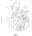
- Figs. 5 and 6 there are shown diagrams of state changes of the speed governor assembly when the sheave reaches the second speed, according to an embodiment.
- the triggering arm 7 can contact and trigger the overspeed protection switch 20, and when the core ring 5 is rotated at a second angle ( Fig. 6 ), the rocker arm 6 is fully pulled up, at which point the mechanical brake acts and the second angle is greater than or at least equal to the first angle.
- the triggering arm 7 is connected to the rocker arm 6 and the rocker arm 6 is connected to the core ring 5.
- the triggering arm 7 can be directly connected to the core ring 5 or indirectly connected to the core ring 5 as long as it can rotate with the core ring 5 and trigger the overspeed protection switch 20.
- the rocker arm 6 has a first end 61 and a second end 62.
- the first end 61 of the rocker arm 6 is connected to the core ring 5, for example through three bolts 63.
- the second end 62 of the rocker arm 6 has a connection port 64 for connection with a safety gear pull rod (not shown).
- a safety gear pull rod not shown.
- the second end 62 of the rocker arm 6 passes through the opening 11 on the side of the frame.
- the rocker arm 6 is shaped as a plate and substantially triangular.
- the centrifugal mechanism 4 includes a plurality of centrifugal block supports 41 each carrying a centrifugal block 42, (three centrifugal block supports 41 shown in the illustrated embodiment), and a plurality of connecting rods 43 connected between the plurality of centrifugal block supports 41, with a retaining mechanism, such as a spring device or a magnetic device, holding the plurality of centrifugal block supports 41 together.
- a retaining mechanism such as a spring device or a magnetic device
- centrifugal block supports 41 When the sheave 3 reaches the first speed, the centrifugal block supports 41 are deployed to the extent that enables triggering the overspeed protection switch 20.
- a roller 44 inside the plurality of connecting rods 43 of the centrifugal mechanism 4 engages the core ring 5 and drives the core ring 5 and the rocker arm 6 to rotate, triggering the mechanical brake device.
- the specific structure of the centrifugal mechanism 4 can be of the type described in U.S. Patent Publication No. US20130098711A1 to Otis Elevator Company.
- an elevator system configured with the speed governor assembly described according to various embodiments.
- the speed governor assembly may be mounted to the elevator car and the elevator system may be a low speed elevator, such as where the basic running speed of the car is less than 1.0 m/s.
Landscapes
- Engineering & Computer Science (AREA)
- Automation & Control Theory (AREA)
- Mechanical Engineering (AREA)
- Computer Networks & Wireless Communication (AREA)
- Maintenance And Inspection Apparatuses For Elevators (AREA)
Applications Claiming Priority (1)
| Application Number | Priority Date | Filing Date | Title |
|---|---|---|---|
| CN201810378395.7A CN110395641B (zh) | 2018-04-25 | 2018-04-25 | 限速器组件和电梯系统 |
Publications (3)
| Publication Number | Publication Date |
|---|---|
| EP3560875A2 true EP3560875A2 (fr) | 2019-10-30 |
| EP3560875A3 EP3560875A3 (fr) | 2019-11-06 |
| EP3560875B1 EP3560875B1 (fr) | 2024-09-25 |
Family
ID=66218012
Family Applications (1)
| Application Number | Title | Priority Date | Filing Date |
|---|---|---|---|
| EP19169970.1A Active EP3560875B1 (fr) | 2018-04-25 | 2019-04-17 | Régulateur de vitesse et système d'ascenseur |
Country Status (4)
| Country | Link |
|---|---|
| US (1) | US11465881B2 (fr) |
| EP (1) | EP3560875B1 (fr) |
| CN (1) | CN110395641B (fr) |
| ES (1) | ES2988829T3 (fr) |
Cited By (1)
| Publication number | Priority date | Publication date | Assignee | Title |
|---|---|---|---|---|
| CN111173858A (zh) * | 2020-03-05 | 2020-05-19 | 无锡瑞吉德机械有限公司 | 一种重型离心触发式安全锁 |
Families Citing this family (3)
| Publication number | Priority date | Publication date | Assignee | Title |
|---|---|---|---|---|
| CN111115406B (zh) * | 2020-01-17 | 2024-09-17 | 苏州普乐太自控技术有限公司 | 一种具有防溜车功能的电梯 |
| CN113948973A (zh) * | 2021-10-26 | 2022-01-18 | 江苏赛尼电力科技有限公司 | 一种提高安全性的配电盘用防误开开关辅助组件 |
| CN117819335A (zh) * | 2022-09-29 | 2024-04-05 | 奥的斯电梯公司 | 限速器组件、电梯安全装置和电梯系统 |
Citations (1)
| Publication number | Priority date | Publication date | Assignee | Title |
|---|---|---|---|---|
| US20130098711A1 (en) | 2010-05-18 | 2013-04-25 | Otis Elevator Company | Integrated elevator safety system |
Family Cites Families (24)
| Publication number | Priority date | Publication date | Assignee | Title |
|---|---|---|---|---|
| JPH04365771A (ja) | 1991-06-13 | 1992-12-17 | Toshiba Corp | エレベータ |
| GB2264283B (en) * | 1992-02-21 | 1995-02-15 | Sunrise Medical Ltd | Overspeed governor of a stairlift and method of operating the stairlift |
| CN1167595C (zh) | 1998-02-26 | 2004-09-22 | 三菱电机株式会社 | 电梯调速器的检查与调节方法 |
| JP4109384B2 (ja) | 1999-05-27 | 2008-07-02 | 三菱電機株式会社 | エレベータ調速機 |
| CN100386251C (zh) | 2002-04-24 | 2008-05-07 | 三菱电机株式会社 | 用于电梯系统的超速调节器装置 |
| JP4276036B2 (ja) * | 2003-09-18 | 2009-06-10 | 株式会社日立製作所 | エレベータ用調速機 |
| WO2005061362A1 (fr) | 2003-11-18 | 2005-07-07 | Otis Elevator Company | Dispositif regulateur d'ascenseur |
| CN100540436C (zh) * | 2005-02-24 | 2009-09-16 | 三菱电机株式会社 | 电梯用限速器 |
| KR100602875B1 (ko) * | 2005-10-07 | 2006-07-19 | 성원금속(주) | 엘리베이터 승강 조속기 |
| JP4802787B2 (ja) * | 2006-03-20 | 2011-10-26 | 株式会社日立製作所 | エレベーターの安全装置 |
| EP2144835B1 (fr) * | 2007-04-13 | 2014-07-16 | Otis Elevator Company | Poulie de régulateur avec un système à masselotte chevauchante |
| CN100575234C (zh) | 2008-04-08 | 2009-12-30 | 宁波申菱电梯配件有限公司 | 电梯限速器 |
| CN201211988Y (zh) * | 2008-05-06 | 2009-03-25 | 河北东方富达机械有限公司 | 电梯限速器 |
| CN101445199B (zh) | 2008-12-23 | 2011-05-25 | 日立电梯(中国)有限公司 | 电梯限速器触发机构 |
| RU2491224C2 (ru) | 2009-03-16 | 2013-08-27 | Отис Элевэйтор Компани | Система защиты лифта от превышения ускорения и превышения скорости |
| KR101271404B1 (ko) * | 2011-11-15 | 2013-06-05 | 오티스 엘리베이터 컴파니 | 승강기용 조속기 |
| EP2928804B1 (fr) | 2012-12-10 | 2017-02-15 | Inventio AG | Installation d'ascenseur dotée d'un limiteur de vitesse |
| CN203461654U (zh) | 2013-08-12 | 2014-03-05 | 谭锦泉 | 一种限速触发器 |
| CN204549702U (zh) | 2015-03-06 | 2015-08-12 | 苏州科达液压电梯有限公司 | 一种电梯限速器 |
| CN205151436U (zh) * | 2015-11-26 | 2016-04-13 | 上海乐天电梯部件有限公司 | 限速器 |
| CN205472083U (zh) | 2015-12-31 | 2016-08-17 | 允成机电科技(上海)有限公司 | 一种电梯限速器弹簧式涨紧装置 |
| CN205739856U (zh) * | 2016-06-22 | 2016-11-30 | 朗格尔电梯有限公司 | 具有安全检测功能的电梯限速器 |
| CN106986249A (zh) * | 2017-05-04 | 2017-07-28 | 宁波申菱电梯配件有限公司 | 远程可操作控制无机房限速器 |
| CN209143433U (zh) * | 2018-03-15 | 2019-07-23 | 杭州沪宁电梯部件股份有限公司 | 绳轮限速器触发机构 |
-
2018
- 2018-04-25 CN CN201810378395.7A patent/CN110395641B/zh active Active
-
2019
- 2019-04-17 ES ES19169970T patent/ES2988829T3/es active Active
- 2019-04-17 EP EP19169970.1A patent/EP3560875B1/fr active Active
- 2019-04-23 US US16/391,974 patent/US11465881B2/en active Active
Patent Citations (1)
| Publication number | Priority date | Publication date | Assignee | Title |
|---|---|---|---|---|
| US20130098711A1 (en) | 2010-05-18 | 2013-04-25 | Otis Elevator Company | Integrated elevator safety system |
Cited By (1)
| Publication number | Priority date | Publication date | Assignee | Title |
|---|---|---|---|---|
| CN111173858A (zh) * | 2020-03-05 | 2020-05-19 | 无锡瑞吉德机械有限公司 | 一种重型离心触发式安全锁 |
Also Published As
| Publication number | Publication date |
|---|---|
| EP3560875A3 (fr) | 2019-11-06 |
| CN110395641A (zh) | 2019-11-01 |
| US11465881B2 (en) | 2022-10-11 |
| EP3560875B1 (fr) | 2024-09-25 |
| ES2988829T3 (es) | 2024-11-21 |
| US20190330019A1 (en) | 2019-10-31 |
| CN110395641B (zh) | 2021-12-14 |
Similar Documents
| Publication | Publication Date | Title |
|---|---|---|
| EP3560875B1 (fr) | Régulateur de vitesse et système d'ascenseur | |
| JP5287859B2 (ja) | エレベータ用調速機 | |
| EP2673232B1 (fr) | Régulateur d'ascenseur doté de deux mécanismes de déclenchement sur des faisceaux distincts | |
| US11078044B2 (en) | Ring assembly for elevator governor, governor and elevator system | |
| EP3628627B1 (fr) | Commutateur de protection contre la survitesse, ensemble de régulateur de survitesse et système d'ascenseur | |
| CN114634127B (zh) | 一种具有防缠绕功能的伺服卷扬机 | |
| US6296080B1 (en) | Variable traction mechanism for rotary actuated overspeed safety device | |
| CN110733952A (zh) | 一种高可靠电梯限速器 | |
| EP2490971B1 (fr) | Régulateur du movement accidentel et ascenseur | |
| CN204823557U (zh) | 限速器 | |
| US11591185B2 (en) | Remote triggering device, overspeed governor assembly and elevator system | |
| CN211338415U (zh) | 机械触发装置 | |
| CN204873325U (zh) | 限速器 | |
| CN211283313U (zh) | 一种高可靠电梯限速器 | |
| JP7685164B1 (ja) | エレベータ調速機及びエレベータ | |
| CN110217664B (zh) | 机械触发装置 | |
| EP1577248B1 (fr) | Ascenseur et corde de reglage de la vitesse | |
| CN112141849A (zh) | 用于电梯系统的限速器组件、电梯安全系统和电梯系统 | |
| CN111377329A (zh) | 一种高速电梯限速器用离心触发机构 | |
| CN211338412U (zh) | 电气触发机构 | |
| JP2012111574A (ja) | 乗客コンベア | |
| JP4580748B2 (ja) | エレベータの調速機 | |
| CN113277105A (zh) | 一种飞机短距起飞助速装置 | |
| TR2021007463A2 (tr) | Asansör terti̇batlari i̇çi̇n bi̇r hiz regülatörü | |
| JPH02102465A (ja) | 断線検出装置 |
Legal Events
| Date | Code | Title | Description |
|---|---|---|---|
| PUAI | Public reference made under article 153(3) epc to a published international application that has entered the european phase |
Free format text: ORIGINAL CODE: 0009012 |
|
| STAA | Information on the status of an ep patent application or granted ep patent |
Free format text: STATUS: THE APPLICATION HAS BEEN PUBLISHED |
|
| PUAL | Search report despatched |
Free format text: ORIGINAL CODE: 0009013 |
|
| AK | Designated contracting states |
Kind code of ref document: A2 Designated state(s): AL AT BE BG CH CY CZ DE DK EE ES FI FR GB GR HR HU IE IS IT LI LT LU LV MC MK MT NL NO PL PT RO RS SE SI SK SM TR |
|
| AX | Request for extension of the european patent |
Extension state: BA ME |
|
| AK | Designated contracting states |
Kind code of ref document: A3 Designated state(s): AL AT BE BG CH CY CZ DE DK EE ES FI FR GB GR HR HU IE IS IT LI LT LU LV MC MK MT NL NO PL PT RO RS SE SI SK SM TR |
|
| AX | Request for extension of the european patent |
Extension state: BA ME |
|
| RIC1 | Information provided on ipc code assigned before grant |
Ipc: B66B 5/04 20060101AFI20190930BHEP |
|
| STAA | Information on the status of an ep patent application or granted ep patent |
Free format text: STATUS: REQUEST FOR EXAMINATION WAS MADE |
|
| 17P | Request for examination filed |
Effective date: 20200522 |
|
| RBV | Designated contracting states (corrected) |
Designated state(s): AL AT BE BG CH CY CZ DE DK EE ES FI FR GB GR HR HU IE IS IT LI LT LU LV MC MK MT NL NO PL PT RO RS SE SI SK SM TR |
|
| STAA | Information on the status of an ep patent application or granted ep patent |
Free format text: STATUS: EXAMINATION IS IN PROGRESS |
|
| 17Q | First examination report despatched |
Effective date: 20220520 |
|
| GRAP | Despatch of communication of intention to grant a patent |
Free format text: ORIGINAL CODE: EPIDOSNIGR1 |
|
| STAA | Information on the status of an ep patent application or granted ep patent |
Free format text: STATUS: GRANT OF PATENT IS INTENDED |
|
| INTG | Intention to grant announced |
Effective date: 20240419 |
|
| GRAS | Grant fee paid |
Free format text: ORIGINAL CODE: EPIDOSNIGR3 |
|
| GRAA | (expected) grant |
Free format text: ORIGINAL CODE: 0009210 |
|
| STAA | Information on the status of an ep patent application or granted ep patent |
Free format text: STATUS: THE PATENT HAS BEEN GRANTED |
|
| AK | Designated contracting states |
Kind code of ref document: B1 Designated state(s): AL AT BE BG CH CY CZ DE DK EE ES FI FR GB GR HR HU IE IS IT LI LT LU LV MC MK MT NL NO PL PT RO RS SE SI SK SM TR |
|
| REG | Reference to a national code |
Ref country code: GB Ref legal event code: FG4D |
|
| REG | Reference to a national code |
Ref country code: CH Ref legal event code: EP |
|
| REG | Reference to a national code |
Ref country code: DE Ref legal event code: R096 Ref document number: 602019059354 Country of ref document: DE |
|
| REG | Reference to a national code |
Ref country code: IE Ref legal event code: FG4D |
|
| REG | Reference to a national code |
Ref country code: ES Ref legal event code: FG2A Ref document number: 2988829 Country of ref document: ES Kind code of ref document: T3 Effective date: 20241121 |
|
| REG | Reference to a national code |
Ref country code: LT Ref legal event code: MG9D |
|
| PG25 | Lapsed in a contracting state [announced via postgrant information from national office to epo] |
Ref country code: NO Free format text: LAPSE BECAUSE OF FAILURE TO SUBMIT A TRANSLATION OF THE DESCRIPTION OR TO PAY THE FEE WITHIN THE PRESCRIBED TIME-LIMIT Effective date: 20241225 |
|
| PG25 | Lapsed in a contracting state [announced via postgrant information from national office to epo] |
Ref country code: GR Free format text: LAPSE BECAUSE OF FAILURE TO SUBMIT A TRANSLATION OF THE DESCRIPTION OR TO PAY THE FEE WITHIN THE PRESCRIBED TIME-LIMIT Effective date: 20241226 Ref country code: FI Free format text: LAPSE BECAUSE OF FAILURE TO SUBMIT A TRANSLATION OF THE DESCRIPTION OR TO PAY THE FEE WITHIN THE PRESCRIBED TIME-LIMIT Effective date: 20240925 |
|
| PG25 | Lapsed in a contracting state [announced via postgrant information from national office to epo] |
Ref country code: BG Free format text: LAPSE BECAUSE OF FAILURE TO SUBMIT A TRANSLATION OF THE DESCRIPTION OR TO PAY THE FEE WITHIN THE PRESCRIBED TIME-LIMIT Effective date: 20240925 |
|
| PG25 | Lapsed in a contracting state [announced via postgrant information from national office to epo] |
Ref country code: LV Free format text: LAPSE BECAUSE OF FAILURE TO SUBMIT A TRANSLATION OF THE DESCRIPTION OR TO PAY THE FEE WITHIN THE PRESCRIBED TIME-LIMIT Effective date: 20240925 |
|
| PG25 | Lapsed in a contracting state [announced via postgrant information from national office to epo] |
Ref country code: RS Free format text: LAPSE BECAUSE OF FAILURE TO SUBMIT A TRANSLATION OF THE DESCRIPTION OR TO PAY THE FEE WITHIN THE PRESCRIBED TIME-LIMIT Effective date: 20241225 |
|
| REG | Reference to a national code |
Ref country code: NL Ref legal event code: MP Effective date: 20240925 |
|
| PG25 | Lapsed in a contracting state [announced via postgrant information from national office to epo] |
Ref country code: RS Free format text: LAPSE BECAUSE OF FAILURE TO SUBMIT A TRANSLATION OF THE DESCRIPTION OR TO PAY THE FEE WITHIN THE PRESCRIBED TIME-LIMIT Effective date: 20241225 Ref country code: NO Free format text: LAPSE BECAUSE OF FAILURE TO SUBMIT A TRANSLATION OF THE DESCRIPTION OR TO PAY THE FEE WITHIN THE PRESCRIBED TIME-LIMIT Effective date: 20241225 Ref country code: LV Free format text: LAPSE BECAUSE OF FAILURE TO SUBMIT A TRANSLATION OF THE DESCRIPTION OR TO PAY THE FEE WITHIN THE PRESCRIBED TIME-LIMIT Effective date: 20240925 Ref country code: GR Free format text: LAPSE BECAUSE OF FAILURE TO SUBMIT A TRANSLATION OF THE DESCRIPTION OR TO PAY THE FEE WITHIN THE PRESCRIBED TIME-LIMIT Effective date: 20241226 Ref country code: FI Free format text: LAPSE BECAUSE OF FAILURE TO SUBMIT A TRANSLATION OF THE DESCRIPTION OR TO PAY THE FEE WITHIN THE PRESCRIBED TIME-LIMIT Effective date: 20240925 Ref country code: BG Free format text: LAPSE BECAUSE OF FAILURE TO SUBMIT A TRANSLATION OF THE DESCRIPTION OR TO PAY THE FEE WITHIN THE PRESCRIBED TIME-LIMIT Effective date: 20240925 |
|
| REG | Reference to a national code |
Ref country code: AT Ref legal event code: MK05 Ref document number: 1726519 Country of ref document: AT Kind code of ref document: T Effective date: 20240925 |
|
| PG25 | Lapsed in a contracting state [announced via postgrant information from national office to epo] |
Ref country code: NL Free format text: LAPSE BECAUSE OF FAILURE TO SUBMIT A TRANSLATION OF THE DESCRIPTION OR TO PAY THE FEE WITHIN THE PRESCRIBED TIME-LIMIT Effective date: 20240925 |
|
| PG25 | Lapsed in a contracting state [announced via postgrant information from national office to epo] |
Ref country code: PT Free format text: LAPSE BECAUSE OF FAILURE TO SUBMIT A TRANSLATION OF THE DESCRIPTION OR TO PAY THE FEE WITHIN THE PRESCRIBED TIME-LIMIT Effective date: 20250127 Ref country code: IS Free format text: LAPSE BECAUSE OF FAILURE TO SUBMIT A TRANSLATION OF THE DESCRIPTION OR TO PAY THE FEE WITHIN THE PRESCRIBED TIME-LIMIT Effective date: 20250125 |
|
| PG25 | Lapsed in a contracting state [announced via postgrant information from national office to epo] |
Ref country code: RO Free format text: LAPSE BECAUSE OF FAILURE TO SUBMIT A TRANSLATION OF THE DESCRIPTION OR TO PAY THE FEE WITHIN THE PRESCRIBED TIME-LIMIT Effective date: 20240925 Ref country code: SM Free format text: LAPSE BECAUSE OF FAILURE TO SUBMIT A TRANSLATION OF THE DESCRIPTION OR TO PAY THE FEE WITHIN THE PRESCRIBED TIME-LIMIT Effective date: 20240925 |
|
| PG25 | Lapsed in a contracting state [announced via postgrant information from national office to epo] |
Ref country code: AT Free format text: LAPSE BECAUSE OF FAILURE TO SUBMIT A TRANSLATION OF THE DESCRIPTION OR TO PAY THE FEE WITHIN THE PRESCRIBED TIME-LIMIT Effective date: 20240925 Ref country code: EE Free format text: LAPSE BECAUSE OF FAILURE TO SUBMIT A TRANSLATION OF THE DESCRIPTION OR TO PAY THE FEE WITHIN THE PRESCRIBED TIME-LIMIT Effective date: 20240925 |
|
| PG25 | Lapsed in a contracting state [announced via postgrant information from national office to epo] |
Ref country code: CZ Free format text: LAPSE BECAUSE OF FAILURE TO SUBMIT A TRANSLATION OF THE DESCRIPTION OR TO PAY THE FEE WITHIN THE PRESCRIBED TIME-LIMIT Effective date: 20240925 Ref country code: PL Free format text: LAPSE BECAUSE OF FAILURE TO SUBMIT A TRANSLATION OF THE DESCRIPTION OR TO PAY THE FEE WITHIN THE PRESCRIBED TIME-LIMIT Effective date: 20240925 |
|
| PG25 | Lapsed in a contracting state [announced via postgrant information from national office to epo] |
Ref country code: SK Free format text: LAPSE BECAUSE OF FAILURE TO SUBMIT A TRANSLATION OF THE DESCRIPTION OR TO PAY THE FEE WITHIN THE PRESCRIBED TIME-LIMIT Effective date: 20240925 Ref country code: IT Free format text: LAPSE BECAUSE OF FAILURE TO SUBMIT A TRANSLATION OF THE DESCRIPTION OR TO PAY THE FEE WITHIN THE PRESCRIBED TIME-LIMIT Effective date: 20240925 |
|
| REG | Reference to a national code |
Ref country code: DE Ref legal event code: R097 Ref document number: 602019059354 Country of ref document: DE |
|
| PGFP | Annual fee paid to national office [announced via postgrant information from national office to epo] |
Ref country code: DE Payment date: 20250319 Year of fee payment: 7 |
|
| PG25 | Lapsed in a contracting state [announced via postgrant information from national office to epo] |
Ref country code: DK Free format text: LAPSE BECAUSE OF FAILURE TO SUBMIT A TRANSLATION OF THE DESCRIPTION OR TO PAY THE FEE WITHIN THE PRESCRIBED TIME-LIMIT Effective date: 20240925 |
|
| PGFP | Annual fee paid to national office [announced via postgrant information from national office to epo] |
Ref country code: ES Payment date: 20250502 Year of fee payment: 7 |
|
| PLBE | No opposition filed within time limit |
Free format text: ORIGINAL CODE: 0009261 |
|
| STAA | Information on the status of an ep patent application or granted ep patent |
Free format text: STATUS: NO OPPOSITION FILED WITHIN TIME LIMIT |
|
| 26N | No opposition filed |
Effective date: 20250626 |
|
| PG25 | Lapsed in a contracting state [announced via postgrant information from national office to epo] |
Ref country code: SE Free format text: LAPSE BECAUSE OF FAILURE TO SUBMIT A TRANSLATION OF THE DESCRIPTION OR TO PAY THE FEE WITHIN THE PRESCRIBED TIME-LIMIT Effective date: 20240925 |
|
| REG | Reference to a national code |
Ref country code: CH Ref legal event code: H13 Free format text: ST27 STATUS EVENT CODE: U-0-0-H10-H13 (AS PROVIDED BY THE NATIONAL OFFICE) Effective date: 20251125 |
|
| PG25 | Lapsed in a contracting state [announced via postgrant information from national office to epo] |
Ref country code: LU Free format text: LAPSE BECAUSE OF NON-PAYMENT OF DUE FEES Effective date: 20250417 |
|
| PG25 | Lapsed in a contracting state [announced via postgrant information from national office to epo] |
Ref country code: MC Free format text: LAPSE BECAUSE OF FAILURE TO SUBMIT A TRANSLATION OF THE DESCRIPTION OR TO PAY THE FEE WITHIN THE PRESCRIBED TIME-LIMIT Effective date: 20240925 |
|
| GBPC | Gb: european patent ceased through non-payment of renewal fee |
Effective date: 20250417 |
|
| REG | Reference to a national code |
Ref country code: BE Ref legal event code: MM Effective date: 20250430 |
|
| PG25 | Lapsed in a contracting state [announced via postgrant information from national office to epo] |
Ref country code: GB Free format text: LAPSE BECAUSE OF NON-PAYMENT OF DUE FEES Effective date: 20250417 |
|
| PG25 | Lapsed in a contracting state [announced via postgrant information from national office to epo] |
Ref country code: HR Free format text: LAPSE BECAUSE OF FAILURE TO SUBMIT A TRANSLATION OF THE DESCRIPTION OR TO PAY THE FEE WITHIN THE PRESCRIBED TIME-LIMIT Effective date: 20240925 |
|
| PG25 | Lapsed in a contracting state [announced via postgrant information from national office to epo] |
Ref country code: BE Free format text: LAPSE BECAUSE OF NON-PAYMENT OF DUE FEES Effective date: 20250430 |
|
| PG25 | Lapsed in a contracting state [announced via postgrant information from national office to epo] |
Ref country code: CH Free format text: LAPSE BECAUSE OF NON-PAYMENT OF DUE FEES Effective date: 20250430 |
|
| PG25 | Lapsed in a contracting state [announced via postgrant information from national office to epo] |
Ref country code: IE Free format text: LAPSE BECAUSE OF NON-PAYMENT OF DUE FEES Effective date: 20250417 |
|
| PGFP | Annual fee paid to national office [announced via postgrant information from national office to epo] |
Ref country code: FR Payment date: 20260319 Year of fee payment: 8 |