EP3561187A2 - Toilette mit verstecktem ablauf - Google Patents
Toilette mit verstecktem ablauf Download PDFInfo
- Publication number
- EP3561187A2 EP3561187A2 EP19170591.2A EP19170591A EP3561187A2 EP 3561187 A2 EP3561187 A2 EP 3561187A2 EP 19170591 A EP19170591 A EP 19170591A EP 3561187 A2 EP3561187 A2 EP 3561187A2
- Authority
- EP
- European Patent Office
- Prior art keywords
- basin
- connector
- lavatory
- pipe
- overflow pipe
- Prior art date
- Legal status (The legal status is an assumption and is not a legal conclusion. Google has not performed a legal analysis and makes no representation as to the accuracy of the status listed.)
- Granted
Links
Images






Classifications
-
- E—FIXED CONSTRUCTIONS
- E03—WATER SUPPLY; SEWERAGE
- E03C—DOMESTIC PLUMBING INSTALLATIONS FOR FRESH WATER OR WASTE WATER; SINKS
- E03C1/00—Domestic plumbing installations for fresh water or waste water; Sinks
- E03C1/12—Plumbing installations for waste water; Basins or fountains connected thereto; Sinks
- E03C1/22—Outlet devices mounted in basins, baths, or sinks
-
- E—FIXED CONSTRUCTIONS
- E03—WATER SUPPLY; SEWERAGE
- E03C—DOMESTIC PLUMBING INSTALLATIONS FOR FRESH WATER OR WASTE WATER; SINKS
- E03C1/00—Domestic plumbing installations for fresh water or waste water; Sinks
- E03C1/12—Plumbing installations for waste water; Basins or fountains connected thereto; Sinks
- E03C1/14—Wash-basins connected to the waste-pipe
-
- E—FIXED CONSTRUCTIONS
- E03—WATER SUPPLY; SEWERAGE
- E03C—DOMESTIC PLUMBING INSTALLATIONS FOR FRESH WATER OR WASTE WATER; SINKS
- E03C1/00—Domestic plumbing installations for fresh water or waste water; Sinks
- E03C1/12—Plumbing installations for waste water; Basins or fountains connected thereto; Sinks
- E03C1/18—Sinks, whether or not connected to the waste-pipe
- E03C1/182—Sinks, whether or not connected to the waste-pipe connected to the waste-pipe
-
- E—FIXED CONSTRUCTIONS
- E03—WATER SUPPLY; SEWERAGE
- E03C—DOMESTIC PLUMBING INSTALLATIONS FOR FRESH WATER OR WASTE WATER; SINKS
- E03C1/00—Domestic plumbing installations for fresh water or waste water; Sinks
- E03C1/12—Plumbing installations for waste water; Basins or fountains connected thereto; Sinks
- E03C1/22—Outlet devices mounted in basins, baths, or sinks
- E03C1/23—Outlet devices mounted in basins, baths, or sinks with mechanical closure mechanisms
-
- E—FIXED CONSTRUCTIONS
- E03—WATER SUPPLY; SEWERAGE
- E03C—DOMESTIC PLUMBING INSTALLATIONS FOR FRESH WATER OR WASTE WATER; SINKS
- E03C1/00—Domestic plumbing installations for fresh water or waste water; Sinks
- E03C1/12—Plumbing installations for waste water; Basins or fountains connected thereto; Sinks
- E03C1/22—Outlet devices mounted in basins, baths, or sinks
- E03C1/23—Outlet devices mounted in basins, baths, or sinks with mechanical closure mechanisms
- E03C1/2302—Outlet devices mounted in basins, baths, or sinks with mechanical closure mechanisms the actuation force being transmitted to the plug via rigid elements
-
- E—FIXED CONSTRUCTIONS
- E03—WATER SUPPLY; SEWERAGE
- E03C—DOMESTIC PLUMBING INSTALLATIONS FOR FRESH WATER OR WASTE WATER; SINKS
- E03C1/00—Domestic plumbing installations for fresh water or waste water; Sinks
- E03C1/12—Plumbing installations for waste water; Basins or fountains connected thereto; Sinks
- E03C1/22—Outlet devices mounted in basins, baths, or sinks
- E03C1/23—Outlet devices mounted in basins, baths, or sinks with mechanical closure mechanisms
- E03C1/232—Outlet devices mounted in basins, baths, or sinks with mechanical closure mechanisms combined with overflow devices
-
- E—FIXED CONSTRUCTIONS
- E03—WATER SUPPLY; SEWERAGE
- E03C—DOMESTIC PLUMBING INSTALLATIONS FOR FRESH WATER OR WASTE WATER; SINKS
- E03C1/00—Domestic plumbing installations for fresh water or waste water; Sinks
- E03C1/12—Plumbing installations for waste water; Basins or fountains connected thereto; Sinks
- E03C1/24—Overflow devices for basins or baths
Definitions
- the present application generally relates to the field of lavatories (e.g., sinks, etc.). Specifically, the present application relates to a lavatory having a hidden drain.
- lavatories e.g., sinks, etc.
- the present application relates to a lavatory having a hidden drain.
- a lavatory may include a basin and a primary drain opening configured to receive a flow of water from the basin and thereby drain the water from the basin.
- the primary drain opening is configured to prevent water from accumulating in the basin.
- primary drain openings are often visible to users of the lavatory, thereby decreasing the aesthetic appearance of the user while the user uses the lavatory because foreign matter can collect at or around the primary drain opening. Accordingly, typical lavatories must be regularly cleaned to maintain the aesthetic appearance of the lavatory.
- a lavatory may have a secondary drain opening located on a side of the basin of the lavatory.
- the secondary drain opening is configured to receive a water flow from the basin when the primary drain opening of the basin is blocked or clogged. Accordingly, the secondary drain opening is configured to maintain the water level in the basin at or below a predetermined level when the primary drain opening is blocked or clogged. Because the secondary drain opening is typically located on a side of the basin, the secondary drain opening creates difficult to clean areas on the side of the basin such that foreign matter can collect at or around the secondary opening, decreasing both the aesthetic appearance of the basin and the cleanliness of the basin. Additionally, because additional piping is required to connect the secondary drain opening to a plumbing system, the secondary drain opening reduces the amount of potential storage space beneath the lavatory.
- a lavatory includes a basin including a bottom surface, the basin configured to hold a volume of water; and a drain opening disposed in the bottom surface of the basin.
- the bottom surface of the basin comprises a substantially horizontally extending projection formed integrally with the bottom surface of the basin.
- the horizontally extending projection is disposed over the drain opening such that the drain opening is at least partially obscured from a view of a user.
- the drain opening is disposed in a middle portion of the bottom surface of the basin.
- the basin further comprises a chamber disposed beneath and in fluid communication with the drain opening.
- the chamber is configured to receive a first fluid flow from the drain opening and provide a second fluid flow to a waste.
- the chamber is configured to house at least a portion of an overflow pipe, the overflow pipe in fluid communication with the waste.
- a lavatory system includes a basin configured to hold a volume of water, the basin including a bottom surface; and a drain opening disposed in the bottom surface of the basin; and a hidden chamber disposed beneath the basin.
- the hidden chamber includes a fluid inlet and a fluid outlet and is configured to receive a fluid flow from the drain opening of the basin; and a drain assembly including an overflow pipe including a first end and a second end, the overflow pipe being moveable from a first position to a second position; and a waste in fluid communication with the fluid outlet of the hidden chamber.
- the overflow pipe In the first position of the overflow pipe, fluid flows from the hidden chamber into the waste without flowing through the pipe and in the second position of the overflow pipe, fluid flow flows from the hidden chamber into the waste via the overflow pipe.
- the basin is configured to hold a volume of water when the overflow pipe is in the second position.
- the bottom surface of the basin comprises a horizontally extending projection formed integrally with the bottom surface of the basin.
- the horizontally extending projection is disposed over the drain such that the drain opening is at least partially obscured from a view of a user.
- the first end of the overflow pipe is housed within the hidden chamber.
- the lavatory system also includes a connecting rod connected to the overflow pipe and extending at least partially from the second end of the overflow pipe.
- the lavatory system also includes a pop-up rod assembly connected to the connecting rod, the pop-up rod assembly being configured to control a movement of the overflow pipe from the first position to the second position.
- the drain assembly also includes a first connector configured to be fluidly sealed to the fluid outlet of the hidden chamber.
- the drain assembly also includes a second connector configured to be fluidly sealed to the first connector and further configured to be connected to the waste.
- a drain assembly for a lavatory includes a pipe configured to receive a fluid flow, the pipe being moveable from a first position to a second position; a first connector comprising a first end portion including an inner diameter and a second end portion including an inner diameter and an outer diameter; and a second connector including a first end portion comprising an inner diameter configured to fit over and around the outer diameter of the second end portion of the first connector and a second end portion configured to be connected to a first waste.
- the first end portion of the first connector is configured to be connected to a fluid outlet of the lavatory. In the first position an end of the pipe is configured to be housed within an inner surface of the first connector and in the second position the end of the pipe is configured to be housed within an inner surface of the second connector.
- the drain assembly in the first position of the pipe, is configured to allow a fluid flow from a drain opening of the lavatory into the first waste without flowing through the pipe. In the second position, the drain assembly is configured to allow a fluid flow from the drain opening of the lavatory into the first waste via the pipe.
- the outer diameter of the second portion of the first connector includes a thread and the inner diameter of the first end portion of the second connector includes a thread configured to mate with the thread of the outer diameter of the second portion of the first connector.
- the drain assembly for a lavatory also includes a second waste configured to be housed within an inner surface of the second connector.
- the pipe includes a connecting rod connected to the pipe, the connecting rod being configured to be connected to a pop-up rod assembly of the lavatory.
- the pop-up rod assembly of the lavatory is configured to control a movement of the pipe between the first position and the second position.
- the end of the pipe is configured to be housed in a chamber of the lavatory.
- the first waste is connectable to an external plumbing system.
- lavatories and drain assemblies useable with a lavatory. These lavatories and drain assemblies are useable for providing an aethestically pleasing lavatory by at least partially obscuring a drain opening and drain assembly from a user of the lavatory. Additionally, the lavatories and drain assemblies useable with a lavatory herein disclosed provide minimal difficult-to-clean areas in a lavatory basin.
- the lavatory system 1 includes a basin 10 and a chamber 30 (e.g., hidden chamber) configured to be in fluid communication with the basin 10.
- the lavatory system 1 also includes a drain assembly 50 configured to be in fluid communication with the chamber 30 and further configured to be connectable to an external plumbing system.
- the configuration of the basin 10 and chamber 30 allows for a storage area 40 disposed beneath the basin 10.
- the basin 10 is configured to receive a fluid flow (such as a flow of water) from a fluid source, such as a faucet (not shown) connected to a faucet neck 20.
- the basin 10 is also configured to hold a volume of fluid within the basin 10.
- the basin 10 is formed of any suitable material, for example, a ceramic material.
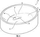
- the basin 10 includes a basin side wall 11 and a bottom surface 12.
- the bottom surface 12 includes a first portion 13 and a second portion 14.
- the first portion 13 and the second portion 14 of the bottom surface 12 define a drain opening 16.
- the shape of the basin 10 is not particularly limited to this implementation.
- the shape of the basin 10 may be any suitable shape such that the basin 10 is configured to hold a volume of fluid.
- the basin 10 can have a rectangular horizontal cross-section such that the basin side wall 11 includes a front wall, a back wall, a left side wall, and a right side wall.
- the basin 10 is connected to basin support 25, which is configured to support the basin 10, either independently or dependently (e.g., by anchoring the basin support 25 to a wall).
- a projection 15 is formed integrally with the bottom surface 12.
- the projection 15 is formed integrally with the first portion 13 of the bottom surface 12 of the basin 10.
- the projection 15 extends substantially horizontally from the bottom surface 12 of the basin (for example, from the first portion 13 of the bottom surface 12).
- the projection 15 is disposed over and/or above the drain opening 16 of the basin 10.
- the projection 15 is configured to at least partially obscure from a view of a user the drain opening 16 of the basin 10.
- the projection 15 is configured to completely obscure from the view of the user the drain opening 16 of the basin 10.
- the projection 15 can be positioned along a side wall 11 of the basin 10, for example, a front wall, a back wall, a left side wall, or a right side wall of the basin 10.
- the chamber 30 includes a fluid inlet 31 fluidly coupled with the drain opening 16 of the basin 10 and a fluid outlet 32 fluidly coupled to a channel 50 (as described in more detail below).
- the chamber 30 is defined by side walls 33 and a bottom wall 34.
- the chamber 30 includes a first chamber portion 30a and a second chamber portion 30b.
- the first chamber portion 30a is defined by side walls 33, a bottom side of at least part of the first portion 13 of the bottom surface 12 and a bottom side of at least part of the second portion 14 of the bottom surface 12.
- the second chamber portion 30b is defined by side walls 33, the bottom side of at least part of the second portion 14 of the bottom surface 12, and the bottom wall 34.
- the chamber 30 is disposed beneath the drain opening 16 such that a fluid held within basin 10 can flow through the drain opening 16 of the basin 10 and into the chamber 30 via the fluid inlet 31 of the chamber 30.
- the chamber 30 is oriented beneath the projection 15 such that view of the chamber 30 of a user of the lavatory system 1 is at least partially obscured by the projection 15.
- the chamber 30 is shown integrally formed with the basin 10, according to an additional aspect, the chamber 30 is detachably coupled to the basin 10.
- the orientation of the chamber 30 relative to the basin 10, and the drain opening 16 of the basin 10 specifically, allows for a storage area 40 to be positioned beneath the chamber 30.
- the storage area 40 is configured to store items related to the use of the lavatory system 1.
- the shape and/or size of the storage area 40 is of any suitable shape and/or size allowed by the relative orientation, placement, and size of the basin 10 and the chamber 30.
- the drainage assembly 50 includes a horizontally oriented channel 51, a vertically oriented channel 52, and an outlet channel 55.
- the drainage assembly 50 includes a fluid inlet 53 fluidly coupled to the fluid outlet 32 of the chamber 30.
- the fluid inlet 53 of the drainage assembly 50 is directly connected to the horizontally oriented channel 51.
- the drainage assembly 50 also includes fluid outlet 54 which is fluidly coupled to an external plumbing system (e.g., a plumbing system of a building) (not shown).
- the fluid inlet 53 of the drainage assembly 50 is configured to facilitate a fluid flow from the chamber 30 to the fluid outlet 54 of the drainage assembly 50 and thereby to the external plumbing system.
- the horizontally oriented channel 51, the vertically oriented channel 52, and the outlet channel 55 are made of any suitable material, for example, plastic or ceramic.
- the drainage assembly 50 also includes a first connector 70, a second connector 80, and a waste 95.
- the first connector 70 (described in more detail below with reference to drainage assembly 250) and the second connector 80 (described in more detail below with reference to drainage assembly 250) are disposed between the vertically oriented channel 52 of the drainage assembly and the outlet channel 55 of the drainage assembly 50.
- the lavatory system 1 also includes a pop-rod assembly 90.
- the pop-up rod assembly 90 is configured to control the fluid flow within the drainage assembly from the chamber 30 to the external plumbing system, in the manner as described in more detail below with reference to drainage assembly 250.
- the pop-up rod assembly 90 includes a handle 91 whereby a user can control movement of the components of the pop-up rod assembly 90.
- the pop-up rod assembly 90 also includes a first connecting rod 92 which is connected directly to the handle 91.
- the pop-up rod assembly 90 also includes a connecting rod 93 which is connected directly to the waste 95.
- the connecting rod 92 and the connecting rod 93 are connected via connector 94.
- the lavatory system 2 includes a basin 210.
- the basin 210 is configured to receive a fluid flow (such as a flow of water) from a fluid source, such as a faucet (not shown).
- the basin 210 is also configured to hold a volume of fluid within the basin 210.
- the basin 210 is formed of any suitable material, for example, a ceramic material.
- the basin 210 includes a bottom surface 212 including a first portion 213 and a second portion 214.
- the first portion 213 and the second portion 214 define a drain opening 216 which is configured to allow a fluid flow 200 out of the basin 210.
- the drain opening 216 is at least partially obscured from the view of a user by a projection or lip 215.
- the projection 215 entirely obscured from the view of the user the drain opening 216.
- the projection 215 is integrally formed with the first portion 213 of the bottom surface 212 of the basin 210.
- the lavatory system also includes basin support 225 which is configured to either independently or dependently support the basin 210.
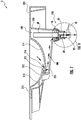
- the basin 210 also includes a chamber (e.g., hidden chamber) 230 which is fluidly coupled to the basin 210.
- the chamber 230 is defined by the second portion 214 of the bottom surface 212 of the basin 210 and walls 233, including side walls and a bottom wall.
- the chamber 230 is configured such that the fluid flow 200 from the basin 210 via the drain opening 216 is received into chamber 230.
- the lavatory system 2 also includes a drainage assembly 250.
- the drainage assembly 250 includes an overflow pipe (e.g., channel) 60.
- the overflow pipe is configured to move from a first position (shown in FIG. 7 ), in which the fluid flow 200 flows out of the chamber 230 without first flowing through the overflow pipe 60, to a second position (shown in FIG. 9 ), in which the fluid flow 200 flows out of the chamber 230 via the overflow pipe 60.
- the overflow pipe 60 is in the second position, the basin 210 is fillable with a volume of fluid (for example, water).
- the various components of the drainage assembly 250 described below are made of suitable materials, for example, plastic or ceramic.
- the overflow pipe 60 includes a first end 61, which is configured to be housed within the chamber 230, and a second end 62.
- the overflow pipe 60 also includes an inner surface 60' having an inner diameter 63.
- the overflow pipe 60 also includes a groove 64 on an outer surface of the overflow pipe 60 configured to house a sealing ring 110 (such as an O-ring) which is configured to seal a connection between the overflow pipe 60 and a first connector 70 and a second connector 80 (as shown in FIGS. 1-3 and as described below in more detail).
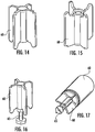
- a sealing member 68 is shown in FIGS. 11-12 and 14-17 .
- the overflow pipe 60 also includes a plurality of inner ribs 67 which are connected to the inner surface 60' of the overflow pipe 60 and which support sleeve 66 connected to the sealing member 68.
- the sealing member 68 is connected to the overflow pipe 60 by any suitable means.
- the sealing member 68 is connected to the overflow pipe 60 via a screw (not shown) which is connected to an end of arm 65 (described below) and which is connectable to the plurality of inner ribs 67.
- the sealing member 68 is connected to the overflow pipe 60 via a snap-fit between the sealing member 68 and the plurality of inner ribs 67.
- Sleeve 66 is configured to hold the arm 65 which extends beyond the end 62 of the overflow pipe 60 and is configured to be connected to connecting rod 93 of pop-up rod assembly 90 (described above).
- connecting rode 93 of the pop-up rod assembly 90 is moved, the arm 65 of the overflow pipe 60 is moved, thereby adjusting a position of the sealing member 68 of the overflow pipe 60 within the drainage assembly 250.
- the sealing member 68 of the overflow pipe is in a first position, fluid flow 200 flows from the chamber 230 into the waste 95 of the drainage assembly 250 without flowing through the overflow pipe 60.
- the sealing member 68 of the overflow pipe is in a second position, fluid flow 201 flows from the chamber 230 through the overflow pipe 60 into the waste 95.
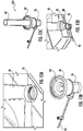
- the first connector 70 includes a first end portion 71 having an inner diameter 73.
- the first end portion 71 is configured to be attached to outlet 35 of chamber 30 (as shown in FIG. 11 ) or to a bottom portion of the chamber 230.
- the first end portion 71 includes a first portion and a second portion oriented at an angle 71a relative to each other.
- the first connector 70 also includes a second end portion 72 having an inner diameter 74 and an outer diameter 75.
- the outer diameter 75 of the second end portion 72 may include thread 76, as shown in FIG. 11 .
- the second end portion 72 includes a first portion and a second portion oriented at an angle 72a relative to each other.
- the second connector 80 is configured to be attached to the second end portion 72 of the first connector 70.
- the second connector 80 includes a first end portion 81 having an inner diameter 83 having thread 86.
- the inner diameter 83 of the first end portion 81 of the second connector 80 is larger than the outer diameter 72 of the second end portion 72 of the first connector 70.
- the thread 86 of the first end portion 81 of the second connector 80 is configured to mate with the thread 76 of the second end portion 72 of the first connector 70.
- the second connector 80 also includes a second end portion 82 which includes an inner diameter 84 which is configured to be connected to a waste 95.
- the second end portion 82 is also configured to receive a sealing ring 120 which is configured to seal a connection between the second end portion 82 of the second connector 80 and the waste 95.
- the second connector 80 also includes a middle portion 85 disposed between the first end portion 81 and the second end portion 82.
- the first end portion 81 and the middle portion 85 are oriented at an angle 81a relative to each other.
- the second end portion 82 and the middle portion 85 are oriented at an angle 82a relative to each other.
- the middle portion 85 is configured such that a sealing ring 115 sits in the first end portion 81 and against the middle portion 85 such that the sealing ring 115 is held in place.
- the middle portion 85 is also configured to house and hold a waste 100 within the second connector 80.
- FIG. 13 illustrates a method of assembling the drainage assembly 250 onto a chamber 30 or chamber 230 described above.
- the first connector 70 is affixed to the chamber 30, for example, by using an adhesive.
- a connecting rod 93 of a pop-up rod assembly is connected to the waste 95.
- the waste 95 is the affixed to the second connector 80 and the waste 100 is placed inside the second connector 80.
- the drainage assembly 250 is assembled by inserting the overflow pipe 60 into the second connector 80 and thereby secured to the waste 95.
- the second connector 80 is affixed (for example, by using an adhesive) to the first connector 70, completing the assembly of the drainage assembly 250 and securably attaching the drainage assembly 250 to the chamber 30 or chamber 230 of a lavatory system.
- Coupled means the joining of two members directly or indirectly to one another. Such joining may be stationary (e.g., permanent) or moveable (e.g., removable or releasable). Such joining may be achieved with the two members or the two members and any additional intermediate members being integrally formed as a single unitary body with one another or with the two members or the two members and any additional intermediate members being attached to one another.
Landscapes
- Engineering & Computer Science (AREA)
- Environmental & Geological Engineering (AREA)
- Health & Medical Sciences (AREA)
- Life Sciences & Earth Sciences (AREA)
- Hydrology & Water Resources (AREA)
- Public Health (AREA)
- Water Supply & Treatment (AREA)
- Mechanical Engineering (AREA)
- Sink And Installation For Waste Water (AREA)
- Sanitary Device For Flush Toilet (AREA)
Priority Applications (1)
| Application Number | Priority Date | Filing Date | Title |
|---|---|---|---|
| EP20180561.1A EP3733985B1 (de) | 2018-04-25 | 2019-04-23 | Toilette mit verstecktem ablauf |
Applications Claiming Priority (1)
| Application Number | Priority Date | Filing Date | Title |
|---|---|---|---|
| US201862662336P | 2018-04-25 | 2018-04-25 |
Related Child Applications (2)
| Application Number | Title | Priority Date | Filing Date |
|---|---|---|---|
| EP20180561.1A Division EP3733985B1 (de) | 2018-04-25 | 2019-04-23 | Toilette mit verstecktem ablauf |
| EP20180561.1A Division-Into EP3733985B1 (de) | 2018-04-25 | 2019-04-23 | Toilette mit verstecktem ablauf |
Publications (3)
| Publication Number | Publication Date |
|---|---|
| EP3561187A2 true EP3561187A2 (de) | 2019-10-30 |
| EP3561187A3 EP3561187A3 (de) | 2020-01-08 |
| EP3561187B1 EP3561187B1 (de) | 2021-03-03 |
Family
ID=66248609
Family Applications (2)
| Application Number | Title | Priority Date | Filing Date |
|---|---|---|---|
| EP19170591.2A Active EP3561187B1 (de) | 2018-04-25 | 2019-04-23 | Toilette mit verstecktem ablauf |
| EP20180561.1A Active EP3733985B1 (de) | 2018-04-25 | 2019-04-23 | Toilette mit verstecktem ablauf |
Family Applications After (1)
| Application Number | Title | Priority Date | Filing Date |
|---|---|---|---|
| EP20180561.1A Active EP3733985B1 (de) | 2018-04-25 | 2019-04-23 | Toilette mit verstecktem ablauf |
Country Status (3)
| Country | Link |
|---|---|
| US (2) | US11001995B2 (de) |
| EP (2) | EP3561187B1 (de) |
| CN (1) | CN110397124B (de) |
Cited By (2)
| Publication number | Priority date | Publication date | Assignee | Title |
|---|---|---|---|---|
| EP4015719A1 (de) * | 2020-12-15 | 2022-06-22 | Elleci S.p.A. | Ablaufvorrichtung, insbesondere für küchenspülen |
| EP4063575A1 (de) * | 2021-03-24 | 2022-09-28 | Geberit International AG | Waschtischanordnung |
Families Citing this family (1)
| Publication number | Priority date | Publication date | Assignee | Title |
|---|---|---|---|---|
| DE102023101439A1 (de) * | 2023-01-20 | 2024-07-25 | Grohe Ag | Abflusseinrichtung für eine Sanitäreinrichtung und Sanitäreinrichtung mit einer Abflusseinrichtung |
Family Cites Families (28)
| Publication number | Priority date | Publication date | Assignee | Title |
|---|---|---|---|---|
| US2767407A (en) * | 1956-10-23 | Sink construction | ||
| US1195684A (en) | 1916-08-22 | John f | ||
| US1183568A (en) * | 1914-09-30 | 1916-05-16 | Raymond H Keevan | Automatically-acting waste appliance for a lavatory. |
| US1786641A (en) * | 1928-09-04 | 1930-12-30 | Berg Knute | Chain saw |
| US1784641A (en) * | 1929-04-06 | 1930-12-09 | William H Oldfield | Lavatory or washstand |
| FR2110476A5 (en) * | 1970-10-19 | 1972-06-02 | Dimpre Henri | Combined syphon and outlet - for lavatory system |
| US4765002A (en) | 1983-03-21 | 1988-08-23 | American Standard Inc. | Lavatory |
| SE8406083D0 (sv) * | 1984-11-30 | 1984-11-30 | Traderic Belgium Pvba | I sanitera utslagsenheter inbyggt dolt vattenlasmekanism |
| JPS6471934A (en) * | 1987-09-11 | 1989-03-16 | Keraamaku Keraamishie Werke Ag | Drainage system |
| BE1008069A3 (nl) * | 1994-02-09 | 1996-01-09 | Ericson Kurt Sture Birger | Sanitair toestel met indirekte afvoer. |
| DE20019579U1 (de) * | 2000-11-15 | 2001-02-01 | Scherer, Norbert, 66773 Schwalbach | Beckenablauf |
| EP1267005A3 (de) * | 2001-06-14 | 2004-01-28 | Geberit Technik Ag | Ablaufgarnitur für ein Becken oder eine Wanne |
| EP1288379A1 (de) | 2001-08-29 | 2003-03-05 | Michael Dr. Gerloff | Ablauf für ein Waschbecken mit einem schlitzförmigen Auslauf |
| DK1367185T3 (da) * | 2002-05-28 | 2005-12-27 | Rapsel S P A | Håndvask med skjult aflöb |
| DE20304759U1 (de) * | 2003-03-24 | 2003-07-31 | Alape Adolf Lamprecht GmbH & Co. KG, 38644 Goslar | Waschbecken |
| US20070130687A1 (en) * | 2003-07-23 | 2007-06-14 | Marc Sadler | Sanitary connection and draine device |
| BRPI0605437B1 (pt) * | 2006-11-22 | 2022-04-05 | Duratex S.A | Arranjo de escoamento de água em uma cuba de lavatório |
| US7941878B1 (en) * | 2007-07-23 | 2011-05-17 | Daniel Danh Truong | Sink drain system |
| DE202008015030U1 (de) * | 2008-11-13 | 2009-02-26 | Scherer, Norbert | Raumsparsifon |
| CN201598684U (zh) * | 2009-12-22 | 2010-10-06 | 于佳楣 | 一种节水型洗手盆 |
| DE202010016411U1 (de) * | 2010-12-09 | 2012-03-13 | Rehau Ag + Co | Abführvorrichtung zum Abführen von Fluid |
| MX341172B (es) | 2010-12-21 | 2016-08-10 | As Ip Holdo Llc | Lavabo lavamanos colgado en la pared para evitar la propagacion de una enfermedad infecciosa. |
| CN104350217A (zh) * | 2012-06-07 | 2015-02-11 | 埃克扎西巴西建筑材料工业有限公司 | 开发为用于在卫生设备产品中使用的且包括隐藏的溢流系统的节省空间的水排放系统 |
| GB201405235D0 (en) * | 2014-03-24 | 2014-05-07 | Mcalpine & Co Ltd | Improved plumbing apparatus |
| CN204715474U (zh) * | 2015-04-08 | 2015-10-21 | 济南大学 | 利用位能差的自动节水系统 |
| CN104929201A (zh) * | 2015-05-29 | 2015-09-23 | 九牧厨卫股份有限公司 | 一种隐藏式溢流台盆 |
| CN105113583B (zh) | 2015-08-05 | 2019-04-09 | 西安建筑科技大学 | 一种节水型卫生器具 |
| US11015329B2 (en) * | 2016-06-08 | 2021-05-25 | Bradley Corporation | Lavatory drain system |
-
2019
- 2019-04-23 EP EP19170591.2A patent/EP3561187B1/de active Active
- 2019-04-23 EP EP20180561.1A patent/EP3733985B1/de active Active
- 2019-04-23 US US16/392,249 patent/US11001995B2/en active Active
- 2019-04-25 CN CN201910340603.9A patent/CN110397124B/zh active Active
-
2021
- 2021-05-04 US US17/307,156 patent/US12281467B2/en active Active
Non-Patent Citations (1)
| Title |
|---|
| None |
Cited By (2)
| Publication number | Priority date | Publication date | Assignee | Title |
|---|---|---|---|---|
| EP4015719A1 (de) * | 2020-12-15 | 2022-06-22 | Elleci S.p.A. | Ablaufvorrichtung, insbesondere für küchenspülen |
| EP4063575A1 (de) * | 2021-03-24 | 2022-09-28 | Geberit International AG | Waschtischanordnung |
Also Published As
| Publication number | Publication date |
|---|---|
| EP3733985B1 (de) | 2023-08-23 |
| CN110397124A (zh) | 2019-11-01 |
| US20210254319A1 (en) | 2021-08-19 |
| EP3561187B1 (de) | 2021-03-03 |
| US11001995B2 (en) | 2021-05-11 |
| US12281467B2 (en) | 2025-04-22 |
| CN110397124B (zh) | 2024-07-05 |
| EP3561187A3 (de) | 2020-01-08 |
| US20190345702A1 (en) | 2019-11-14 |
| EP3733985A1 (de) | 2020-11-04 |
Similar Documents
| Publication | Publication Date | Title |
|---|---|---|
| US12281467B2 (en) | Lavatory with hidden drain | |
| US11280074B2 (en) | Wastewater drain stopper system | |
| CA2464407C (en) | Washing platform | |
| CN100417356C (zh) | 带有可移除洗涤平台的盥洗装置 | |
| CA2967603C (en) | Tub spout assembly | |
| US20250305260A1 (en) | Bath faucet system | |
| EP2010727B1 (de) | Entwässerungsabfluss mit integraler klemme zur verwendung mit einer installationsvorrichtung | |
| CN121368664A (zh) | 水龙头组件 | |
| EP2395158B1 (de) | Wasserhahn | |
| EP1689941B1 (de) | Ablaufgarnitur | |
| EP4717839A1 (de) | Wasserüberlauf oder kombinierter wasserüberlauf/einlauf für ein bad | |
| JP6785400B2 (ja) | 排水器の取付構造 | |
| AU2016208288B2 (en) | Waste fitting | |
| JP6445410B2 (ja) | 水栓 | |
| TR2023001716A2 (tr) | Bardak/Sürahi Yıkama Özellikli Su gideri | |
| WO2001068996A1 (en) | Liquid trap | |
| CA2533319A1 (en) | Sanitary connecting and draining device | |
| GB2601708A (en) | A kit for a shower assembly and an adjustable manifold | |
| GB2565560A (en) | A kit for a shower assembly and an adjustable manifold | |
| EP2518228A2 (de) | Vorrichtung zum Verdecken einer Platte in Zusammenhang mit Überlaufinstallation | |
| HU216510B (hu) | Egészségügyi csaptelep | |
| HK1092252B (en) | Lavatory with a removable washing platform |
Legal Events
| Date | Code | Title | Description |
|---|---|---|---|
| PUAI | Public reference made under article 153(3) epc to a published international application that has entered the european phase |
Free format text: ORIGINAL CODE: 0009012 |
|
| STAA | Information on the status of an ep patent application or granted ep patent |
Free format text: STATUS: REQUEST FOR EXAMINATION WAS MADE |
|
| 17P | Request for examination filed |
Effective date: 20190423 |
|
| AK | Designated contracting states |
Kind code of ref document: A2 Designated state(s): AL AT BE BG CH CY CZ DE DK EE ES FI FR GB GR HR HU IE IS IT LI LT LU LV MC MK MT NL NO PL PT RO RS SE SI SK SM TR |
|
| AX | Request for extension of the european patent |
Extension state: BA ME |
|
| PUAL | Search report despatched |
Free format text: ORIGINAL CODE: 0009013 |
|
| AK | Designated contracting states |
Kind code of ref document: A3 Designated state(s): AL AT BE BG CH CY CZ DE DK EE ES FI FR GB GR HR HU IE IS IT LI LT LU LV MC MK MT NL NO PL PT RO RS SE SI SK SM TR |
|
| AX | Request for extension of the european patent |
Extension state: BA ME |
|
| RIC1 | Information provided on ipc code assigned before grant |
Ipc: E03C 1/24 20060101ALI20191202BHEP Ipc: E03C 1/182 20060101AFI20191202BHEP |
|
| GRAP | Despatch of communication of intention to grant a patent |
Free format text: ORIGINAL CODE: EPIDOSNIGR1 |
|
| STAA | Information on the status of an ep patent application or granted ep patent |
Free format text: STATUS: GRANT OF PATENT IS INTENDED |
|
| INTG | Intention to grant announced |
Effective date: 20201012 |
|
| GRAS | Grant fee paid |
Free format text: ORIGINAL CODE: EPIDOSNIGR3 |
|
| GRAA | (expected) grant |
Free format text: ORIGINAL CODE: 0009210 |
|
| STAA | Information on the status of an ep patent application or granted ep patent |
Free format text: STATUS: THE PATENT HAS BEEN GRANTED |
|
| AK | Designated contracting states |
Kind code of ref document: B1 Designated state(s): AL AT BE BG CH CY CZ DE DK EE ES FI FR GB GR HR HU IE IS IT LI LT LU LV MC MK MT NL NO PL PT RO RS SE SI SK SM TR |
|
| REG | Reference to a national code |
Ref country code: GB Ref legal event code: FG4D |
|
| REG | Reference to a national code |
Ref country code: CH Ref legal event code: EP Ref country code: AT Ref legal event code: REF Ref document number: 1367341 Country of ref document: AT Kind code of ref document: T Effective date: 20210315 |
|
| REG | Reference to a national code |
Ref country code: DE Ref legal event code: R096 Ref document number: 602019002868 Country of ref document: DE |
|
| REG | Reference to a national code |
Ref country code: IE Ref legal event code: FG4D |
|
| REG | Reference to a national code |
Ref country code: LT Ref legal event code: MG9D |
|
| PG25 | Lapsed in a contracting state [announced via postgrant information from national office to epo] |
Ref country code: BG Free format text: LAPSE BECAUSE OF FAILURE TO SUBMIT A TRANSLATION OF THE DESCRIPTION OR TO PAY THE FEE WITHIN THE PRESCRIBED TIME-LIMIT Effective date: 20210603 Ref country code: HR Free format text: LAPSE BECAUSE OF FAILURE TO SUBMIT A TRANSLATION OF THE DESCRIPTION OR TO PAY THE FEE WITHIN THE PRESCRIBED TIME-LIMIT Effective date: 20210303 Ref country code: FI Free format text: LAPSE BECAUSE OF FAILURE TO SUBMIT A TRANSLATION OF THE DESCRIPTION OR TO PAY THE FEE WITHIN THE PRESCRIBED TIME-LIMIT Effective date: 20210303 Ref country code: GR Free format text: LAPSE BECAUSE OF FAILURE TO SUBMIT A TRANSLATION OF THE DESCRIPTION OR TO PAY THE FEE WITHIN THE PRESCRIBED TIME-LIMIT Effective date: 20210604 Ref country code: NO Free format text: LAPSE BECAUSE OF FAILURE TO SUBMIT A TRANSLATION OF THE DESCRIPTION OR TO PAY THE FEE WITHIN THE PRESCRIBED TIME-LIMIT Effective date: 20210603 Ref country code: LT Free format text: LAPSE BECAUSE OF FAILURE TO SUBMIT A TRANSLATION OF THE DESCRIPTION OR TO PAY THE FEE WITHIN THE PRESCRIBED TIME-LIMIT Effective date: 20210303 |
|
| REG | Reference to a national code |
Ref country code: NL Ref legal event code: MP Effective date: 20210303 |
|
| REG | Reference to a national code |
Ref country code: AT Ref legal event code: MK05 Ref document number: 1367341 Country of ref document: AT Kind code of ref document: T Effective date: 20210303 |
|
| PG25 | Lapsed in a contracting state [announced via postgrant information from national office to epo] |
Ref country code: SE Free format text: LAPSE BECAUSE OF FAILURE TO SUBMIT A TRANSLATION OF THE DESCRIPTION OR TO PAY THE FEE WITHIN THE PRESCRIBED TIME-LIMIT Effective date: 20210303 Ref country code: LV Free format text: LAPSE BECAUSE OF FAILURE TO SUBMIT A TRANSLATION OF THE DESCRIPTION OR TO PAY THE FEE WITHIN THE PRESCRIBED TIME-LIMIT Effective date: 20210303 Ref country code: PL Free format text: LAPSE BECAUSE OF FAILURE TO SUBMIT A TRANSLATION OF THE DESCRIPTION OR TO PAY THE FEE WITHIN THE PRESCRIBED TIME-LIMIT Effective date: 20210303 Ref country code: RS Free format text: LAPSE BECAUSE OF FAILURE TO SUBMIT A TRANSLATION OF THE DESCRIPTION OR TO PAY THE FEE WITHIN THE PRESCRIBED TIME-LIMIT Effective date: 20210303 |
|
| PG25 | Lapsed in a contracting state [announced via postgrant information from national office to epo] |
Ref country code: NL Free format text: LAPSE BECAUSE OF FAILURE TO SUBMIT A TRANSLATION OF THE DESCRIPTION OR TO PAY THE FEE WITHIN THE PRESCRIBED TIME-LIMIT Effective date: 20210303 |
|
| PG25 | Lapsed in a contracting state [announced via postgrant information from national office to epo] |
Ref country code: SM Free format text: LAPSE BECAUSE OF FAILURE TO SUBMIT A TRANSLATION OF THE DESCRIPTION OR TO PAY THE FEE WITHIN THE PRESCRIBED TIME-LIMIT Effective date: 20210303 Ref country code: AT Free format text: LAPSE BECAUSE OF FAILURE TO SUBMIT A TRANSLATION OF THE DESCRIPTION OR TO PAY THE FEE WITHIN THE PRESCRIBED TIME-LIMIT Effective date: 20210303 Ref country code: CZ Free format text: LAPSE BECAUSE OF FAILURE TO SUBMIT A TRANSLATION OF THE DESCRIPTION OR TO PAY THE FEE WITHIN THE PRESCRIBED TIME-LIMIT Effective date: 20210303 Ref country code: EE Free format text: LAPSE BECAUSE OF FAILURE TO SUBMIT A TRANSLATION OF THE DESCRIPTION OR TO PAY THE FEE WITHIN THE PRESCRIBED TIME-LIMIT Effective date: 20210303 |
|
| PG25 | Lapsed in a contracting state [announced via postgrant information from national office to epo] |
Ref country code: IS Free format text: LAPSE BECAUSE OF FAILURE TO SUBMIT A TRANSLATION OF THE DESCRIPTION OR TO PAY THE FEE WITHIN THE PRESCRIBED TIME-LIMIT Effective date: 20210703 Ref country code: SK Free format text: LAPSE BECAUSE OF FAILURE TO SUBMIT A TRANSLATION OF THE DESCRIPTION OR TO PAY THE FEE WITHIN THE PRESCRIBED TIME-LIMIT Effective date: 20210303 Ref country code: PT Free format text: LAPSE BECAUSE OF FAILURE TO SUBMIT A TRANSLATION OF THE DESCRIPTION OR TO PAY THE FEE WITHIN THE PRESCRIBED TIME-LIMIT Effective date: 20210705 Ref country code: RO Free format text: LAPSE BECAUSE OF FAILURE TO SUBMIT A TRANSLATION OF THE DESCRIPTION OR TO PAY THE FEE WITHIN THE PRESCRIBED TIME-LIMIT Effective date: 20210303 |
|
| REG | Reference to a national code |
Ref country code: DE Ref legal event code: R097 Ref document number: 602019002868 Country of ref document: DE |
|
| PG25 | Lapsed in a contracting state [announced via postgrant information from national office to epo] |
Ref country code: LU Free format text: LAPSE BECAUSE OF NON-PAYMENT OF DUE FEES Effective date: 20210423 |
|
| PLBE | No opposition filed within time limit |
Free format text: ORIGINAL CODE: 0009261 |
|
| STAA | Information on the status of an ep patent application or granted ep patent |
Free format text: STATUS: NO OPPOSITION FILED WITHIN TIME LIMIT |
|
| REG | Reference to a national code |
Ref country code: BE Ref legal event code: MM Effective date: 20210430 |
|
| PG25 | Lapsed in a contracting state [announced via postgrant information from national office to epo] |
Ref country code: ES Free format text: LAPSE BECAUSE OF FAILURE TO SUBMIT A TRANSLATION OF THE DESCRIPTION OR TO PAY THE FEE WITHIN THE PRESCRIBED TIME-LIMIT Effective date: 20210303 Ref country code: MC Free format text: LAPSE BECAUSE OF FAILURE TO SUBMIT A TRANSLATION OF THE DESCRIPTION OR TO PAY THE FEE WITHIN THE PRESCRIBED TIME-LIMIT Effective date: 20210303 Ref country code: AL Free format text: LAPSE BECAUSE OF FAILURE TO SUBMIT A TRANSLATION OF THE DESCRIPTION OR TO PAY THE FEE WITHIN THE PRESCRIBED TIME-LIMIT Effective date: 20210303 Ref country code: DK Free format text: LAPSE BECAUSE OF FAILURE TO SUBMIT A TRANSLATION OF THE DESCRIPTION OR TO PAY THE FEE WITHIN THE PRESCRIBED TIME-LIMIT Effective date: 20210303 |
|
| 26N | No opposition filed |
Effective date: 20211206 |
|
| PG25 | Lapsed in a contracting state [announced via postgrant information from national office to epo] |
Ref country code: SI Free format text: LAPSE BECAUSE OF FAILURE TO SUBMIT A TRANSLATION OF THE DESCRIPTION OR TO PAY THE FEE WITHIN THE PRESCRIBED TIME-LIMIT Effective date: 20210303 |
|
| PG25 | Lapsed in a contracting state [announced via postgrant information from national office to epo] |
Ref country code: IT Free format text: LAPSE BECAUSE OF FAILURE TO SUBMIT A TRANSLATION OF THE DESCRIPTION OR TO PAY THE FEE WITHIN THE PRESCRIBED TIME-LIMIT Effective date: 20210303 Ref country code: IE Free format text: LAPSE BECAUSE OF NON-PAYMENT OF DUE FEES Effective date: 20210423 |
|
| PG25 | Lapsed in a contracting state [announced via postgrant information from national office to epo] |
Ref country code: IS Free format text: LAPSE BECAUSE OF FAILURE TO SUBMIT A TRANSLATION OF THE DESCRIPTION OR TO PAY THE FEE WITHIN THE PRESCRIBED TIME-LIMIT Effective date: 20210703 |
|
| PG25 | Lapsed in a contracting state [announced via postgrant information from national office to epo] |
Ref country code: BE Free format text: LAPSE BECAUSE OF NON-PAYMENT OF DUE FEES Effective date: 20210430 |
|
| REG | Reference to a national code |
Ref country code: CH Ref legal event code: PL |
|
| PG25 | Lapsed in a contracting state [announced via postgrant information from national office to epo] |
Ref country code: LI Free format text: LAPSE BECAUSE OF NON-PAYMENT OF DUE FEES Effective date: 20220430 Ref country code: CH Free format text: LAPSE BECAUSE OF NON-PAYMENT OF DUE FEES Effective date: 20220430 |
|
| PG25 | Lapsed in a contracting state [announced via postgrant information from national office to epo] |
Ref country code: CY Free format text: LAPSE BECAUSE OF FAILURE TO SUBMIT A TRANSLATION OF THE DESCRIPTION OR TO PAY THE FEE WITHIN THE PRESCRIBED TIME-LIMIT Effective date: 20210303 |
|
| PG25 | Lapsed in a contracting state [announced via postgrant information from national office to epo] |
Ref country code: HU Free format text: LAPSE BECAUSE OF FAILURE TO SUBMIT A TRANSLATION OF THE DESCRIPTION OR TO PAY THE FEE WITHIN THE PRESCRIBED TIME-LIMIT; INVALID AB INITIO Effective date: 20190423 |
|
| P01 | Opt-out of the competence of the unified patent court (upc) registered |
Effective date: 20230707 |
|
| PG25 | Lapsed in a contracting state [announced via postgrant information from national office to epo] |
Ref country code: MK Free format text: LAPSE BECAUSE OF FAILURE TO SUBMIT A TRANSLATION OF THE DESCRIPTION OR TO PAY THE FEE WITHIN THE PRESCRIBED TIME-LIMIT Effective date: 20210303 |
|
| PG25 | Lapsed in a contracting state [announced via postgrant information from national office to epo] |
Ref country code: TR Free format text: LAPSE BECAUSE OF FAILURE TO SUBMIT A TRANSLATION OF THE DESCRIPTION OR TO PAY THE FEE WITHIN THE PRESCRIBED TIME-LIMIT Effective date: 20210303 |
|
| PG25 | Lapsed in a contracting state [announced via postgrant information from national office to epo] |
Ref country code: MT Free format text: LAPSE BECAUSE OF FAILURE TO SUBMIT A TRANSLATION OF THE DESCRIPTION OR TO PAY THE FEE WITHIN THE PRESCRIBED TIME-LIMIT Effective date: 20210303 |
|
| PGFP | Annual fee paid to national office [announced via postgrant information from national office to epo] |
Ref country code: DE Payment date: 20250430 Year of fee payment: 7 |
|
| PGFP | Annual fee paid to national office [announced via postgrant information from national office to epo] |
Ref country code: FR Payment date: 20250430 Year of fee payment: 7 |
|
| PGFP | Annual fee paid to national office [announced via postgrant information from national office to epo] |
Ref country code: GB Payment date: 20260324 Year of fee payment: 8 |