EP3561255B1 - Moteur à combustion interne haute performance ayant une gestion améliorée des émissions et procédé de commande d'un tel moteur - Google Patents
Moteur à combustion interne haute performance ayant une gestion améliorée des émissions et procédé de commande d'un tel moteur Download PDFInfo
- Publication number
- EP3561255B1 EP3561255B1 EP19170931.0A EP19170931A EP3561255B1 EP 3561255 B1 EP3561255 B1 EP 3561255B1 EP 19170931 A EP19170931 A EP 19170931A EP 3561255 B1 EP3561255 B1 EP 3561255B1
- Authority
- EP
- European Patent Office
- Prior art keywords
- engine
- chamber
- cylinder
- intake
- combustion chamber
- Prior art date
- Legal status (The legal status is an assumption and is not a legal conclusion. Google has not performed a legal analysis and makes no representation as to the accuracy of the status listed.)
- Active
Links
Images



Classifications
-
- F—MECHANICAL ENGINEERING; LIGHTING; HEATING; WEAPONS; BLASTING
- F02—COMBUSTION ENGINES; HOT-GAS OR COMBUSTION-PRODUCT ENGINE PLANTS
- F02B—INTERNAL-COMBUSTION PISTON ENGINES; COMBUSTION ENGINES IN GENERAL
- F02B19/00—Engines characterised by precombustion chambers
- F02B19/10—Engines characterised by precombustion chambers with fuel introduced partly into pre-combustion chamber, and partly into cylinder
- F02B19/1019—Engines characterised by precombustion chambers with fuel introduced partly into pre-combustion chamber, and partly into cylinder with only one pre-combustion chamber
- F02B19/1023—Engines characterised by precombustion chambers with fuel introduced partly into pre-combustion chamber, and partly into cylinder with only one pre-combustion chamber pre-combustion chamber and cylinder being fed with fuel-air mixture(s)
-
- F—MECHANICAL ENGINEERING; LIGHTING; HEATING; WEAPONS; BLASTING
- F02—COMBUSTION ENGINES; HOT-GAS OR COMBUSTION-PRODUCT ENGINE PLANTS
- F02B—INTERNAL-COMBUSTION PISTON ENGINES; COMBUSTION ENGINES IN GENERAL
- F02B19/00—Engines characterised by precombustion chambers
- F02B19/12—Engines characterised by precombustion chambers with positive ignition
-
- F—MECHANICAL ENGINEERING; LIGHTING; HEATING; WEAPONS; BLASTING
- F01—MACHINES OR ENGINES IN GENERAL; ENGINE PLANTS IN GENERAL; STEAM ENGINES
- F01N—GAS-FLOW SILENCERS OR EXHAUST APPARATUS FOR MACHINES OR ENGINES IN GENERAL; GAS-FLOW SILENCERS OR EXHAUST APPARATUS FOR INTERNAL-COMBUSTION ENGINES
- F01N3/00—Exhaust or silencing apparatus having means for purifying, rendering innocuous, or otherwise treating exhaust
- F01N3/08—Exhaust or silencing apparatus having means for purifying, rendering innocuous, or otherwise treating exhaust for rendering innocuous
- F01N3/10—Exhaust or silencing apparatus having means for purifying, rendering innocuous, or otherwise treating exhaust for rendering innocuous by thermal or catalytic conversion of noxious components of exhaust
- F01N3/18—Exhaust or silencing apparatus having means for purifying, rendering innocuous, or otherwise treating exhaust for rendering innocuous by thermal or catalytic conversion of noxious components of exhaust characterised by methods of operation; Control
- F01N3/20—Exhaust or silencing apparatus having means for purifying, rendering innocuous, or otherwise treating exhaust for rendering innocuous by thermal or catalytic conversion of noxious components of exhaust characterised by methods of operation; Control specially adapted for catalytic conversion
- F01N3/2006—Periodically heating or cooling catalytic reactors, e.g. at cold starting or overheating
-
- F—MECHANICAL ENGINEERING; LIGHTING; HEATING; WEAPONS; BLASTING
- F02—COMBUSTION ENGINES; HOT-GAS OR COMBUSTION-PRODUCT ENGINE PLANTS
- F02B—INTERNAL-COMBUSTION PISTON ENGINES; COMBUSTION ENGINES IN GENERAL
- F02B19/00—Engines characterised by precombustion chambers
- F02B19/16—Chamber shapes or constructions not specific to sub-groups F02B19/02 - F02B19/10
-
- F—MECHANICAL ENGINEERING; LIGHTING; HEATING; WEAPONS; BLASTING
- F02—COMBUSTION ENGINES; HOT-GAS OR COMBUSTION-PRODUCT ENGINE PLANTS
- F02B—INTERNAL-COMBUSTION PISTON ENGINES; COMBUSTION ENGINES IN GENERAL
- F02B23/00—Other engines characterised by special shape or construction of combustion chambers to improve operation
- F02B23/08—Other engines characterised by special shape or construction of combustion chambers to improve operation with positive ignition
-
- F—MECHANICAL ENGINEERING; LIGHTING; HEATING; WEAPONS; BLASTING
- F02—COMBUSTION ENGINES; HOT-GAS OR COMBUSTION-PRODUCT ENGINE PLANTS
- F02P—IGNITION, OTHER THAN COMPRESSION IGNITION, FOR INTERNAL-COMBUSTION ENGINES; TESTING OF IGNITION TIMING IN COMPRESSION-IGNITION ENGINES
- F02P15/00—Electric spark ignition having characteristics not provided for in, or of interest apart from, groups F02P1/00 - F02P13/00 and combined with layout of ignition circuits
- F02P15/02—Arrangements having two or more sparking plugs
-
- F—MECHANICAL ENGINEERING; LIGHTING; HEATING; WEAPONS; BLASTING
- F02—COMBUSTION ENGINES; HOT-GAS OR COMBUSTION-PRODUCT ENGINE PLANTS
- F02P—IGNITION, OTHER THAN COMPRESSION IGNITION, FOR INTERNAL-COMBUSTION ENGINES; TESTING OF IGNITION TIMING IN COMPRESSION-IGNITION ENGINES
- F02P5/00—Advancing or retarding ignition; Control therefor
- F02P5/04—Advancing or retarding ignition; Control therefor automatically, as a function of the working conditions of the engine or vehicle or of the atmospheric conditions
- F02P5/145—Advancing or retarding ignition; Control therefor automatically, as a function of the working conditions of the engine or vehicle or of the atmospheric conditions using electrical means
-
- F—MECHANICAL ENGINEERING; LIGHTING; HEATING; WEAPONS; BLASTING
- F01—MACHINES OR ENGINES IN GENERAL; ENGINE PLANTS IN GENERAL; STEAM ENGINES
- F01N—GAS-FLOW SILENCERS OR EXHAUST APPARATUS FOR MACHINES OR ENGINES IN GENERAL; GAS-FLOW SILENCERS OR EXHAUST APPARATUS FOR INTERNAL-COMBUSTION ENGINES
- F01N2430/00—Influencing exhaust purification, e.g. starting of catalytic reaction, filter regeneration, or the like, by controlling engine operating characteristics
- F01N2430/08—Influencing exhaust purification, e.g. starting of catalytic reaction, filter regeneration, or the like, by controlling engine operating characteristics by modifying ignition or injection timing
-
- F—MECHANICAL ENGINEERING; LIGHTING; HEATING; WEAPONS; BLASTING
- F02—COMBUSTION ENGINES; HOT-GAS OR COMBUSTION-PRODUCT ENGINE PLANTS
- F02B—INTERNAL-COMBUSTION PISTON ENGINES; COMBUSTION ENGINES IN GENERAL
- F02B23/00—Other engines characterised by special shape or construction of combustion chambers to improve operation
- F02B23/08—Other engines characterised by special shape or construction of combustion chambers to improve operation with positive ignition
- F02B2023/085—Other engines characterised by special shape or construction of combustion chambers to improve operation with positive ignition using several spark plugs per cylinder
-
- Y—GENERAL TAGGING OF NEW TECHNOLOGICAL DEVELOPMENTS; GENERAL TAGGING OF CROSS-SECTIONAL TECHNOLOGIES SPANNING OVER SEVERAL SECTIONS OF THE IPC; TECHNICAL SUBJECTS COVERED BY FORMER USPC CROSS-REFERENCE ART COLLECTIONS [XRACs] AND DIGESTS
- Y02—TECHNOLOGIES OR APPLICATIONS FOR MITIGATION OR ADAPTATION AGAINST CLIMATE CHANGE
- Y02T—CLIMATE CHANGE MITIGATION TECHNOLOGIES RELATED TO TRANSPORTATION
- Y02T10/00—Road transport of goods or passengers
- Y02T10/10—Internal combustion engine [ICE] based vehicles
- Y02T10/12—Improving ICE efficiencies
Definitions
- the present invention concerns an internal combustion engine for a motor-vehicle, with direct fuel injection, in particular a high-performance internal combustion engine for a GT motor-vehicle, with improved handling of emissions.
- the present invention furthermore concerns a method for controlling the above-mentioned internal combustion engine.
- High-performance internal combustion engines for automotive use comprising a plurality of cylinders, for example six, eight, ten or twelve, split into two banks which form an angle ranging from 60° to 180° between each other.
- the known engines further comprise an intake manifold for each bank, fed with fresh air (combustion agent for the combustion) and in turn connected to the cylinders of the bank by means of respective intake ducts.
- each bank is connected to a relative exhaust manifold by means of respective exhaust ducts having the function of expelling the combustion products.
- Each exhaust manifold then conveys the exhaust gases expelled from its cylinder bank towards a catalytic system for the abatement of the polluting engine emissions.
- Each cylinder is further associated with at least one intake valve (normally two twin intake valves) for controlling the airflow entering from the intake manifold and with at least one outlet valve (normally two twin outlet valves) for controlling the outflow of exhaust gases towards the exhaust manifold. Furthermore, each cylinder is associated with an injector to cyclically inject fuel into the cylinder. Each cylinder is coupled with a respective piston, which is adapted to slide in a linear manner along the cylinder and is mechanically connected to a crank shaft by means of a connecting rod.
- intake valve normally two twin intake valves
- outlet valve normally two twin outlet valves
- each cylinder is also associated with a spark plug for cyclically determining ignition of the mixture formed by fuel and air present inside the cylinder and triggering the combustion reaction.
- the corresponding intake valves and part of the corresponding intake duct constitute an intake member which has the function of supplying fresh air to the inside of the cylinder.
- the corresponding outlet valves and part of the corresponding exhaust duct constitute an outlet member which has the function of expelling the exhaust gases from the inside of the cylinder.
- the cylinders of each bank are usually obtained inside a base or monoblock; the intake and outlet members associated with each cylinder are instead carried by a head fixed in abutment on the base at an upper axial end of the cylinders.
- each cylinder delimits with the latter and with the head a chamber commonly known as combustion chamber, namely the chamber in which ignition of the mixture formed of the fuel and the air takes place.
- combustion chamber namely the chamber in which ignition of the mixture formed of the fuel and the air takes place.
- Direct injection occurs when the injector feeds the fuel directly into the combustion chamber of the respective cylinder.
- JP 2002 070558 A and US 2014/209057 A1 disclose engines comprising an injector and a first spark plug arranged in a main combustion chamber, and a second spark plug arranged in a pre-chamber.
- a critical point of the known engines is represented by the heating of the catalytic system.
- a catalytic system operates effectively only above a certain temperature value, usually above 300-400°C. Until that moment, abatement of the engine emissions is minimum. This is why a large part of the engine emissions in an emission test cycle are recorded before the catalytic system enters the temperature range necessary for effective operation.
- a catalytic system would heat up quickly only in the case of a high-power requirement by the vehicle driver. At engine start, on the other hand, the power/torque requirement is low.
- the first strategy is to increase the flow rate of the air entering the cylinders at the engine start, consequently obtaining a higher flow rate of the exhaust gases flowing out of each combustion chamber. By doing this only, the engine would produce more torque than that required.
- the spark plug associated with each cylinder produces, during each engine cycle, a very delayed spark inside the combustion chamber thus reducing the torque produced by the idling engine and heating the exhaust gases; in this case, the combustion occurs late in each cylinder and therefore the expansion phase (movement of the respective piston between the top dead centre and the bottom dead centre resulting from ignition in the respective combustion chamber) between the end of the combustion and opening of the respective outlet valve/s is reduced.
- a high flow rate of the exhaust gases is therefore obtained, and a high temperature of the latter which rapidly heat the catalytic system to bring it as quickly as possible to conditions of maximum efficiency.
- the problem is that of establishing the entity of the delay in production of the spark, and therefore the beginning of combustion, that can be tolerated by an engine so that the combustion does not become unstable or the air and fuel mixture does not ignite (phenomenon known as misfire).
- spark coupled injection To obtain an engine that operates well also with a long spark production delay in each cylinder, the strategy commonly known as spark coupled injection has been developed. With this strategy, a small injection of fuel is made in each cylinder just before production of the spark by the spark plug, thus generating turbulence near the spark plug at the critical moment of ignition of the air-fuel mixture. This allows stabilization of the beginning of the combustion, which is the most critical moment for the stability of a positive-ignition engine.
- the engine can run with a delayed ignition of the mixture, with greater incoming airflow rate and therefore with greater outgoing exhaust gas flow rate and greater heating of the latter; also the catalytic system is therefore very rapidly heated at engine start-up and the emissions, particularly significant in this phase, can be reduced.
- the injector must be arranged near the spark plug. Since the injector is usually positioned in the centre of the combustion chamber, the spark plug is often positioned beside the latter adjacent to the area of the outlet valve/s.
- the engines of the type described above operate very well at start-up and perform well also at full load, namely when high torque/power is required by the vehicle driver.
- the object of the present invention is therefore to provide an internal combustion engine for a motor-vehicle, which has low emissions of polluting substances in all operating conditions and, at the same time, offers high performance.
- an internal combustion engine for a motor-vehicle is provided, as claimed in claim 1.
- the present invention also concerns a control method, as claimed in claim 10.
- an internal combustion engine for a motor-vehicle (not illustrated) is indicated overall by 1.
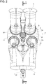
- the engine 1 comprises twelve cylinders 2 arranged in two banks 3a and 3b which form an angle of 90° between each other.
- the cylinders 2 of each bank 3a, 3b have respective axes A parallel to each other.
- the engine 1 is of the type with direct fuel injection into the cylinders 2 to produce an engine cycle including a fuel combustion reaction by means of air.
- the engine 1 is in particular of the high-performance type for a GT motor-vehicle.
- the engine 1 could comprise a different number of cylinders 2 arranged, again, in two banks, or could comprise one single bank or could comprise one single cylinder.
- the angle between the banks could also be different, generally between 60° and 180°.
- the engine 1 further comprises, for each bank 3a, 3b:
- Each exhaust manifold 7 then conveys the exhaust gases expelled from the cylinders 2 of its bank 3a, 3b towards a catalytic system, known per se and not illustrated since it is not part of the present invention.
- each bank 3a, 3b basically comprises a base 10, inside which the respective cylinders 2 and a head 11 are arranged; the intake ducts 6 and exhaust ducts 8 are obtained inside said head which is fixed in a known manner in abutment on an upper side of the base 10 so as to surmount the upper axial ends of the cylinders 2.
- each cylinder 2 is coupled to a respective piston 12, which is linearly movable along the respective axis A inside the cylinder 2 and is mechanically connected to a crank shaft 13 by means of a respective connecting rod 14 ( figure 3 ) ; as can be seen in figure 3 , the crank shaft 13 has an axis D orthogonal to the axes A of the cylinders 2 of the two banks 3a, 3b.
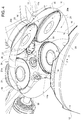
- each head 11 delimits, with a respective cylinder 2 and with the piston 12 movable inside the cylinder 2, a relative combustion chamber 15, in which the entire engine cycle is carried out.
- the intake ducts 6 and exhaust ducts 8 associated with each cylinder 2 communicate with the respective combustion chamber 15 through at least one intake port 16, in the case illustrated two twin intake ports 16, and at least one outlet port 18, in the case illustrated two twin outlet ports 18.
- the airflow entering each combustion chamber 15 is controlled by at least an intake valve 20, in the case illustrated two twin intake valves 20, acting on the respective intake port/s 16.
- the outflow of the exhaust gases from each combustion chamber 15 is controlled by at least one outlet valve 21, in the case illustrated two twin outlet valves 21, acting on the respective outlet port/s 18.
- Each intake valve 20 basically comprises and in a known manner a stem (not illustrated), which moves by sliding in opposite directions within a respective seat (also not illustrated) of the head 11, and a shuttering portion 20a projecting radially from one end of the above-mentioned stem and acting selectively on the respective intake port 16 to close the connection between the respective intake duct 6 and the corresponding combustion chamber 15.
- Each intake valve 20 receives in a known manner driving forces from a relative control device (known per se and not illustrated since it is not part of the present invention), for example a cam shaft, and is elastically loaded in the closing direction of the connection between the respective intake duct 6 and the corresponding combustion chamber 15.
- each outlet valve 21 basically comprises and in a known manner a stem (not illustrated), which moves by sliding in opposite directions within a respective seat (also not illustrated) of the head 11, and a shuttering portion 21a projecting radially from an end of the above-mentioned stem and acting selectively on the respective outlet port 18 to close the connection between the respective exhaust duct 8 and the corresponding combustion chamber 15.
- Each outlet valve 21 receives in a known manner driving forces from the above-mentioned control device and is elastically loaded in the closing direction of the connection between the respective exhaust duct 8 and the corresponding combustion chamber 15.
- the engine 1 further comprises, for each cylinder 2, an injector 22 which can be selectively activated to supply uncombusted fuel inside the respective combustion chamber 15.
- each cylinder 2 the respective head 11 is divided by a centreline plane P of the cylinder 2, containing the respective axis A and parallel to the axis D, in:
- the respective injector 22 is mounted in the respective outlet region 11b of the head 11 in a position adjacent to the respective outlet port/s 18 so that a counterflow of air and fuel is generated in use, adapted to allow effective homogenization of the mixture of the latter.
- the respective head 11 is delimited towards the corresponding piston 12 by a concave surface 23 facing the piston 12: due to this type of conformation, the respective intake regions 11a and outlet regions 11b are at least partially facing each other.
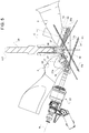
- each injector 22 and each group formed of one of the intake ports 16 and the corresponding intake duct 6 cooperating with said injector 22 are configured to emit respective incoming flows F1, F2 of the fuel and the air, converging towards the centre of the corresponding combustion chamber 15.
- each cylinder 2 is associated with a single intake port 16 and a single intake duct 6, the latter and the corresponding injector 22 are configured to emit respective incoming flows F1, F2 of the fuel and the air, converging towards the centre of the corresponding combustion chamber 15.
- each injector 22 and each intake port 16 cooperating with said injector 22 have respective axes B, C ( figure 5 ) converging towards the centre of the corresponding combustion chamber 15.
- each piston 12 has, on an own face facing the head 11, a cavity 2 opposite the respective concave surface 23 and having the function of creating a vortex action on the air flow F1, so that the latter can effectively mix with the fuel injected by the respective injector 22.
- each cylinder 2 is also associated with at least a first spark plug 24 for cyclically and selectively determining ignition of the fuel-air mixture present in the respective combustion chamber 15 and for triggering the combustion reaction.
- the spark plug 24 is mounted on the head 11 in a position adjacent to the respective injector 22 and projects inside the respective combustion chamber 15; this close proximity between the injector 22 and the spark plug 24 allows, as seen previously, adoption of the strategy commonly known as spark coupled injection and described previously.
- the spark plug 24 associated with each cylinder 2 is mounted inside the respective outlet region 11b of the head 11 and in a position adjacent to each outlet port 18 and on one side with respect to the same.
- the spark plug 24 associated with each cylinder 2 is mounted on the respective head 11 in a position interposed between the two outlet ports 18.
- the engine 1 further comprises, for each cylinder 2:
- each spark plug 24 is arranged in an intermediate position between the respective pre-chamber 26 and the respective injector 22.
- the respective pre-chamber 26 the respective spark plug 24 and the respective injector 22 are arranged along a line transversal to the corresponding axis A.
- the pre-chamber 26 associated with each combustion chamber 15 is of passive type, namely fed only by the air-fuel mixture present in the combustion chamber 15 during movement of the respective piston 12 towards the respective head 11 with consequent compression of the mixture.
- each pre-chamber 26 is carried by the respective head 11 substantially in a central position with respect to the corresponding cylinder 2.
- Each pre-chamber 26 is delimited towards the respective combustion chamber 15 by a wall 30, preferably convex, projecting inside the pre-chamber 26 and bearing the connection ports 27.
- the engine 1 can operate in two different operating conditions:
- the majority of the injection of fuel into each combustion chamber 15 is carried out during the intake phase, while a small injection of fuel is delayed and carried out just before production of the spark by the spark plug 24.
- the piston 12 moves along the axis A of the cylinder 2 from a top dead centre position, in which the piston 12 is arranged at a minimum axial distance from the head 11, to a bottom dead centre position, in which the piston 12 is arranged at a maximum axial distance from the head 11.
- the outlet valves 21 are in the closed position of the respective outlet ports 18, while the intake valves 20 move to an opening position of the connection between the intake ducts 6 and the combustion chamber 15 allowing fresh air to enter the latter through the intake ports 16.
- the engine 1 is in the normal operating condition, i.e. at full load, for example during normal running, injection of the fuel into the combustion chamber 15 by the injector 22 is carried out in this phase. Due to the arrangement of the injector 22 at the outlet region 11b of the head 11, the fuel enters the combustion chamber 15 in counterflow with respect to inlet of the air with consequent particularly effective mixing of the air and fuel particles. Furthermore, the presence of the cavity 25 on the piston 12 allows the establishment of a vortex regime of the incoming air with consequent further improvement of the mixing of air and fuel.
- a compression phase of the air-fuel mixture begins, in which the intake valves 20 move to the closed position of the respective intake ports 16 and the piston 12 moves back up from the bottom dead centre position towards the top dead centre position.
- the air-fuel mixture compressed by the piston 12 also enters the pre-chamber 26 through the connection ports 27.
- the ratio between the mass of the air and that of the fuel in said mixture is of the stoichiometric type.
- optimal operation of the engine 1 also with a ratio between the mass of the air and that of the fuel different from the stoichiometric ratio is not ruled out.
- the subsequent phase is a phase of expansion of the air-fuel mixture resulting from ignition of the same and takes place with the intake valves 20 and outlet valves 21 in the closed position.
- ignition of the mixture is carried out in the pre-chamber 26 by the spark plug 28; due to the arrangement of the pre-chamber 26 in a central position inside the combustion chamber 15, the flame front begins from the centre of the latter and has a minimum distance to cover to burn all the portions of mixture present in the combustion chamber 15; this translates into a rapid combustion with low detonation risk.
- the final phase of the engine cycle is an outlet phase, in which the outlet valves 21 are moved to the opening position and the piston 12 moves back up from the bottom dead centre to the top dead centre with consequent expulsion of the exhaust gases from the combustion chamber 15.
- the airflow entering the combustion chamber 15 during the intake phase is increased and the fuel is injected not only during this later phase but also, to a small extent, just before ignition of the mixture.
- the above-mentioned spark coupled injection strategy is adopted, so that ignition of the mixture is carried out by the spark plug 24, positioned adjacent to the injector 22, immediately after the above-mentioned small injection of fuel performed by the latter.
- the injection of fuel performed just before production of the spark by the spark plug 24 allows the generation of turbulence near to the spark plug 24 at the critical moment of ignition of the mixture. This allows stabilization of the beginning of the combustion, which is the most critical moment for the stability of the engine 1.
- the engine 1 can run with a delayed ignition of the mixture, with greater incoming airflow rate and therefore with greater flow rate of outgoing exhaust gases and greater heating of the latter; the catalytic system can therefore be heated very rapidly at low load, for example at start-up of the engine 1, and the emissions of polluting substances can be reduced, particularly important in this particular operating condition of the engine 1.
- the engine 1 allows high performances to be obtained (due to the presence of a pre-chamber 26 positioned in the centre of each combustion chamber 15) and reduced emissions of polluting substances (due to the arrangement of each injector 22 adjacent to the respective spark plug 24, thus implementing the spark coupled injection strategy at low load, and due to the arrangement of each injector 22 in the outlet region 11b of the head 11 with generation of an air-fuel counterflow during the fuel intake phase).
Landscapes
- Engineering & Computer Science (AREA)
- Chemical & Material Sciences (AREA)
- Combustion & Propulsion (AREA)
- Mechanical Engineering (AREA)
- General Engineering & Computer Science (AREA)
- Chemical Kinetics & Catalysis (AREA)
- Health & Medical Sciences (AREA)
- Toxicology (AREA)
- Combustion Methods Of Internal-Combustion Engines (AREA)
- Ignition Installations For Internal Combustion Engines (AREA)
Claims (11)
- Moteur à combustion interne (1) pour un véhicule à moteur, comprenant :- au moins un cylindre (2) qui comporte un axe longitudinal (A) et qui est adapté pour recevoir du carburant et de l'air pour mettre en œuvre un cycle de moteur qui inclut une réaction de combustion du carburant lui-même ;- au moins un conduit d'admission (6) qui est adapté pour fournir audit cylindre (2) de l'air frais, par l'intermédiaire et au travers d'au moins un orifice d'admission (16) ;- au moins une soupape d'admission (20) qui opère sur ledit orifice d'admission (16) pour réguler l'écoulement d'air qui pénètre à l'intérieur dudit cylindre (2) ;- au moins un injecteur (22) qui peut être activé de façon sélective pour alimenter du carburant non brûlé sur ledit cylindre (2) ;- au moins un conduit d'échappement (8) qui communique avec ledit cylindre (2) par l'intermédiaire et au travers d'au moins un orifice de sortie (18) pour évacuer hors du cylindre (2) des gaz d'échappement qui sont formés à la fin de ladite combustion ;- au moins une soupape de sortie (21) qui opère sur ledit orifice de sortie (18) pour réguler l'écoulement des gaz d'échappement au niveau de la sortie dudit cylindre (2) ; et- un piston (12) qui est monté d'une manière à coulissement linéaire le long dudit axe longitudinal (A) à l'intérieur dudit cylindre ;dans lequel ledit orifice d'admission (16), ledit orifice de sortie (18) et ledit injecteur (22) sont supportés par une tête à fonction de culasse (11) du moteur (1), ladite tête à fonction de culasse (11) étant agencée en butée contre une extrémité axiale dudit cylindre (2) et délimitant, avec ledit piston (12) et avec le cylindre (2), une chambre de combustion (15) ;
ledit moteur (1) comprenant en outre :- au moins une première bougie d'allumage (24) qui est montée sur ladite tête à fonction de culasse (11) et qui opère à l'intérieur de ladite chambre de combustion (15) pour déterminer, de façon cyclique et de manière sélective, l'inflammation du mélange qui est formé par du carburant et par de l'air et qui est présent à l'intérieur de la chambre de combustion (15) et pour déclencher la réaction de combustion ;- une préchambre (26), qui est délimitée en direction de ladite chambre de combustion (15) par une paroi (30), qui communique avec la chambre de combustion (15) par l'intermédiaire et au travers d'un ou de plusieurs orifice(s) de connexion libre(s) (27) et qui est alimentée par un mélange d'air et de carburant ; et- une seconde bougie d'allumage (28) qui opère à l'intérieur de ladite préchambre (26) pour déterminer, de façon cyclique et de manière sélective, l'inflammation du mélange qui est présent à l'intérieur de la préchambre (26) et pour déclencher la réaction de combustion ;- ladite première bougie d'allumage (24) étant agencée en une position intermédiaire entre ladite préchambre (26) et ledit injecteur (22) ;caractérisé en ce que :- ladite première bougie d'allumage (24) est située en une position qui est adjacente audit injecteur (22) ; et- ladite préchambre (26) est agencée en une position centrale à l'intérieur de ladite chambre de combustion (15). - Moteur selon la revendication 1, dans lequel ladite préchambre (26) est seulement alimentée avec le mélange de carburant et d'air qui est présent dans ladite chambre de combustion (15) pendant le mouvement dudit piston (12) en direction de ladite tête à fonction de culasse (11) avec une compression en conséquence du mélange lui-même.
- Moteur selon la revendication 1 ou 2, dans lequel ladite préchambre (26) est supportée par ladite tête à fonction de culasse (11) en une position sensiblement centrale par rapport audit cylindre (2).
- Moteur selon l'une quelconque des revendications précédentes, dans lequel ladite préchambre (26) est délimitée en direction de ladite chambre de combustion (15) par une paroi convexe (30) qui fait saillie à l'intérieur de ladite chambre de combustion (15) et qui supporte lesdits un ou plusieurs orifices de connexion (27).
- Moteur selon l'une quelconque des revendications précédentes, dans lequel ladite préchambre (26), ladite première bougie d'allumage (24) et ledit injecteur (22) sont agencés suivant une ligne qui est transversale par rapport audit axe longitudinal (A).
- Moteur selon l'une quelconque des revendications précédentes, dans lequel ladite tête à fonction de culasse (11) est divisée par un plan de ligne centrale (P) dudit cylindre (2), qui contient ledit axe longitudinal (A), selon :- une région d'admission (11a) qui inclut ledit orifice d'admission (16) et qui est agencée sur un côté dudit plan de ligne centrale (P) ; et selon- une région de sortie (11b) qui inclut ledit orifice de sortie (18) et qui est agencée sur un côté opposé dudit plan de ligne centrale (P) ;et dans lequel ledit injecteur (22) est monté dans ladite région de sortie (11b) de ladite tête à fonction de culasse (11) en une position qui est adjacente audit orifice de sortie (18).
- Moteur selon la revendication 6, dans lequel ladite tête à fonction de culasse (11) est délimitée en direction dudit piston (12) par une surface concave (23) qui fait face au piston (12) ; et dans lequel lesdites régions d'admission (11a) et lesdites régions de sortie (11b) se font au moins partiellement face les unes les autres.
- Moteur selon l'une quelconque des revendications précédentes, dans lequel ledit injecteur (22) et le groupe qui est formé par ledit orifice d'admission (16) et par ledit conduit d'admission (6) sont configurés pour émettre des écoulements d'entrée (F1, F2), respectivement du carburant et de l'air, qui convergent entre eux en direction du centre de ladite chambre de combustion (15).
- Moteur selon l'une quelconque des revendications précédentes, comprenant une pluralité desdits cylindres (2) qui sont agencés de telle sorte qu'ils se fassent face les uns les autres selon un groupe ou plusieurs groupes (3a, 3b) qui sont agencés selon un angle les uns par rapport aux autres, une pluralité desdites chambres de combustion (15) et, pour chaque dit cylindre (2), au moins un dit orifice d'admission (16), au moins un dit orifice de sortie (18), au moins une dite soupape d'admission (20), au moins une dite soupape de sortie (21), au moins un dit injecteur (22), au moins une dite préchambre (26), au moins une dite première bougie d'allumage (24) et au moins une dite seconde bougie d'allumage (28) qui opèrent à l'intérieur de ladite préchambre (26).
- Procédé pour commander un moteur à combustion interne (1) selon l'une quelconque des revendications précédentes, caractérisé en ce qu'il comprend les étapes constituées par :- le pilotage de ladite première bougie d'allumage (24) selon une première condition opérationnelle dudit moteur (1) ; et- le pilotage de ladite seconde bougie d'allumage (28) à l'intérieur de ladite préchambre (26) selon une seconde condition opérationnelle du moteur (1) qui est différente de ladite première condition opérationnelle.
- Procédé selon la revendication 10, dans lequel ladite première condition opérationnelle est une condition opérationnelle particulière du fonctionnement à charge faible dudit moteur (1), en particulier pendant le démarrage du moteur (1), et dans lequel ladite seconde condition opérationnelle est une condition opérationnelle normale du fonctionnement dudit moteur (1) à pleine charge.
Applications Claiming Priority (1)
| Application Number | Priority Date | Filing Date | Title |
|---|---|---|---|
| IT102018000004821A IT201800004821A1 (it) | 2018-04-24 | 2018-04-24 | Motore a combustione interna ad alte prestazioni con gestione delle emissioni migliorata e metodo di controllo di tale motore |
Publications (2)
| Publication Number | Publication Date |
|---|---|
| EP3561255A1 EP3561255A1 (fr) | 2019-10-30 |
| EP3561255B1 true EP3561255B1 (fr) | 2021-02-24 |
Family
ID=63014795
Family Applications (1)
| Application Number | Title | Priority Date | Filing Date |
|---|---|---|---|
| EP19170931.0A Active EP3561255B1 (fr) | 2018-04-24 | 2019-04-24 | Moteur à combustion interne haute performance ayant une gestion améliorée des émissions et procédé de commande d'un tel moteur |
Country Status (3)
| Country | Link |
|---|---|
| US (1) | US11891945B2 (fr) |
| EP (1) | EP3561255B1 (fr) |
| IT (1) | IT201800004821A1 (fr) |
Cited By (2)
| Publication number | Priority date | Publication date | Assignee | Title |
|---|---|---|---|---|
| DE102021113860B3 (de) | 2021-05-28 | 2022-10-06 | Dr. Ing. H.C. F. Porsche Aktiengesellschaft | Verfahren zum Betreiben einer Brennkraftmaschine |
| DE102022124798A1 (de) | 2022-09-27 | 2024-03-28 | Dr. Ing. H.C. F. Porsche Aktiengesellschaft | Verbrennungskraftmaschine mit einer Abgasnachbehandlungseinheit und Verfahren zum Betreiben einer Verbrennungskraftmaschine mit einer Abgasnachbehandlungseinheit |
Families Citing this family (19)
| Publication number | Priority date | Publication date | Assignee | Title |
|---|---|---|---|---|
| EP3434887B1 (fr) * | 2017-07-25 | 2019-08-14 | C.R.F. Società Consortile per Azioni | Moteur à combustion interne à système d'alimentation en gaz |
| EP3453856B1 (fr) * | 2017-09-08 | 2019-10-16 | MASERATI S.p.A. | Moteur à combustion interne à essence, comprenant une préchambre de combustion et deux bougies d'allumage |
| US10995707B1 (en) * | 2019-12-18 | 2021-05-04 | GM Global Technology Operations LLC | Intake air heating with pre-chamber ignition in a gasoline engine |
| FR3115073B1 (fr) | 2020-10-13 | 2026-01-09 | Renault Sas | Bougie d’allumage pour moteur à allumage commandé. |
| DE102020129143A1 (de) * | 2020-11-05 | 2022-05-05 | Bayerische Motoren Werke Aktiengesellschaft | Verfahren zum Betreiben eines Kraftfahrzeugs und Kraftfahrzeug |
| DE102020130836A1 (de) | 2020-11-23 | 2022-05-25 | Bayerische Motoren Werke Aktiengesellschaft | Verbrennungskraftmaschine sowie Verfahren zum Betreiben einer solchen Verbrennungskraftmaschine |
| DE102021102084B4 (de) | 2021-01-29 | 2023-01-12 | Volkswagen Aktiengesellschaft | Zündkerzen-Baugruppe für eine ottomotorische Brennkraftmaschine, umfassend eine Vorkammer- und eine Dachelektrodenzündkerze |
| DE102021104628A1 (de) | 2021-02-26 | 2022-09-01 | Robert Bosch Gesellschaft mit beschränkter Haftung | Verbrennungskraftmaschine mit Zündkerze und Vorkammerzündkerze |
| DE102021104627A1 (de) * | 2021-02-26 | 2022-09-01 | Robert Bosch Gesellschaft mit beschränkter Haftung | Verbrennungskraftmaschine mit Zündkerze und Vorkammerzündkerze |
| DE102021104691A1 (de) | 2021-02-26 | 2022-09-01 | Volkswagen Aktiengesellschaft | Verfahren zum Betreiben einer ottomotorischen Brennkraftmaschine, umfassend eine Zündkerzen-Baugruppe mit einer Vorkammerzündkerze und einer Dachelektrodenzündkerze |
| US11359537B1 (en) | 2021-06-30 | 2022-06-14 | Saudi Arabian Oil Company | Spark ignition engine, pre-chamber, and method for cooling a pre-chamber |
| JP7725920B2 (ja) * | 2021-07-30 | 2025-08-20 | マツダ株式会社 | エンジンシステム |
| JP7647425B2 (ja) * | 2021-07-30 | 2025-03-18 | マツダ株式会社 | エンジンシステム |
| JP7661824B2 (ja) * | 2021-07-30 | 2025-04-15 | マツダ株式会社 | エンジンシステム |
| EP4141226B1 (fr) | 2021-08-27 | 2025-01-29 | António Cameira Eiras, Unipessoal Lda | Véhicule amélioré avec récupération d'énergie des gaz d'échappement |
| DE102021127101B4 (de) | 2021-10-19 | 2023-08-03 | Audi Aktiengesellschaft | Brennkraftmaschine sowie Verfahren zum Betreiben einer Brennkraftmaschine |
| US11725571B1 (en) | 2022-04-27 | 2023-08-15 | Saudi Arabian Oil Company | Spark ignition direct injection engine with active pre-chamber |
| US11788483B1 (en) | 2022-07-06 | 2023-10-17 | Ford Global Technologies, Llc | Method and system for starting an engine |
| DE102022207299A1 (de) * | 2022-07-18 | 2024-01-18 | Robert Bosch Gesellschaft mit beschränkter Haftung | Verfahren und Vorrichtung zur Steuerung einer Brennkraftmaschine |
Family Cites Families (9)
| Publication number | Priority date | Publication date | Assignee | Title |
|---|---|---|---|---|
| JPS5644417A (en) * | 1979-09-17 | 1981-04-23 | Daihatsu Motor Co Ltd | Internal combustion engine with accessory combustion chamber |
| JPS61250364A (ja) * | 1985-04-26 | 1986-11-07 | Mazda Motor Corp | 火花点火式エンジン |
| JPH094459A (ja) * | 1995-06-21 | 1997-01-07 | Isuzu Ceramics Kenkyusho:Kk | 副燃焼室を持つ4サイクルエンジン |
| JPH10318101A (ja) * | 1997-05-20 | 1998-12-02 | Honda Motor Co Ltd | 副燃焼室付き火花点火式内燃機関 |
| JP3840823B2 (ja) * | 1998-12-10 | 2006-11-01 | マツダ株式会社 | 筒内噴射式エンジン |
| JP2002070558A (ja) * | 2000-09-01 | 2002-03-08 | Nissan Motor Co Ltd | 圧縮自己着火式ガソリン内燃機関 |
| JP4502907B2 (ja) * | 2005-03-24 | 2010-07-14 | 本田技研工業株式会社 | 4ストローク内燃機関の可変動弁機構 |
| US9567896B2 (en) * | 2013-01-28 | 2017-02-14 | Sonex Research, Inc. | Method for modifying combustion chamber in a reciprocating piston internal combustion engine and resulting engine |
| EP3453856B1 (fr) * | 2017-09-08 | 2019-10-16 | MASERATI S.p.A. | Moteur à combustion interne à essence, comprenant une préchambre de combustion et deux bougies d'allumage |
-
2018
- 2018-04-24 IT IT102018000004821A patent/IT201800004821A1/it unknown
-
2019
- 2019-04-24 US US16/392,846 patent/US11891945B2/en active Active
- 2019-04-24 EP EP19170931.0A patent/EP3561255B1/fr active Active
Non-Patent Citations (1)
| Title |
|---|
| None * |
Cited By (2)
| Publication number | Priority date | Publication date | Assignee | Title |
|---|---|---|---|---|
| DE102021113860B3 (de) | 2021-05-28 | 2022-10-06 | Dr. Ing. H.C. F. Porsche Aktiengesellschaft | Verfahren zum Betreiben einer Brennkraftmaschine |
| DE102022124798A1 (de) | 2022-09-27 | 2024-03-28 | Dr. Ing. H.C. F. Porsche Aktiengesellschaft | Verbrennungskraftmaschine mit einer Abgasnachbehandlungseinheit und Verfahren zum Betreiben einer Verbrennungskraftmaschine mit einer Abgasnachbehandlungseinheit |
Also Published As
| Publication number | Publication date |
|---|---|
| US11891945B2 (en) | 2024-02-06 |
| EP3561255A1 (fr) | 2019-10-30 |
| US20190323415A1 (en) | 2019-10-24 |
| IT201800004821A1 (it) | 2019-10-24 |
Similar Documents
| Publication | Publication Date | Title |
|---|---|---|
| EP3561255B1 (fr) | Moteur à combustion interne haute performance ayant une gestion améliorée des émissions et procédé de commande d'un tel moteur | |
| CN101900027B (zh) | 采用双重压缩和双重膨胀过程的内燃机 | |
| KR101252668B1 (ko) | 내연엔진의 작동 방법 및 내연엔진 | |
| JP5135372B2 (ja) | 内燃機関 | |
| CN116057262B (zh) | 内燃机及其运行方法 | |
| US8800530B2 (en) | Stratified charge port injection engine and method | |
| US11680512B2 (en) | Method for operating an internal combustion engine of a motor vehicle, in particular a motor car | |
| US9115640B2 (en) | Internal combustion engine with a first and a second injecter | |
| CN111164285A (zh) | 用于机动车的内燃机 | |
| CN103089489B (zh) | 能够在均质充量压缩点火模式下运行的内燃机 | |
| KR20130129071A (ko) | 내연기관을 위한 방법 및 시스템 | |
| US8555834B2 (en) | Device and method configured to control valve operation in a piston engine | |
| US11306648B1 (en) | Combustion pre-chamber for an internal combustion engine | |
| JP2009180220A (ja) | 高圧酸素噴射式内燃機関 | |
| JP7633302B2 (ja) | 燃料と空気の混合気に点火するための装置 | |
| CN114941592B (zh) | 内燃机 | |
| US6213088B1 (en) | Method and device for operating an internal combustion engine | |
| JP3225780U (ja) | 低速大型エンジン | |
| CN118103591A (zh) | 内燃机以及用于运行内燃机的方法 | |
| WO2004090320A3 (fr) | Moteur a combustion interne a injection directe d'essence et a allumage commande | |
| EP0156543B1 (fr) | Moteur à combustion interne | |
| CN221002962U (zh) | 发动机和车辆 | |
| RU2770967C1 (ru) | Многотопливный двигатель внутреннего сгорания с противоположно движущимися поршнями | |
| JP3091586U (ja) | 少なくとも1つのシリンダを備える火花点火式内燃機関 | |
| US10309339B2 (en) | Internal combustion engine |
Legal Events
| Date | Code | Title | Description |
|---|---|---|---|
| PUAI | Public reference made under article 153(3) epc to a published international application that has entered the european phase |
Free format text: ORIGINAL CODE: 0009012 |
|
| STAA | Information on the status of an ep patent application or granted ep patent |
Free format text: STATUS: THE APPLICATION HAS BEEN PUBLISHED |
|
| AK | Designated contracting states |
Kind code of ref document: A1 Designated state(s): AL AT BE BG CH CY CZ DE DK EE ES FI FR GB GR HR HU IE IS IT LI LT LU LV MC MK MT NL NO PL PT RO RS SE SI SK SM TR |
|
| AX | Request for extension of the european patent |
Extension state: BA ME |
|
| STAA | Information on the status of an ep patent application or granted ep patent |
Free format text: STATUS: REQUEST FOR EXAMINATION WAS MADE |
|
| 17P | Request for examination filed |
Effective date: 20200429 |
|
| RIC1 | Information provided on ipc code assigned before grant |
Ipc: F02B 19/12 20060101AFI20200715BHEP Ipc: F02B 23/08 20060101ALI20200715BHEP Ipc: F02B 19/16 20060101ALI20200715BHEP |
|
| GRAP | Despatch of communication of intention to grant a patent |
Free format text: ORIGINAL CODE: EPIDOSNIGR1 |
|
| STAA | Information on the status of an ep patent application or granted ep patent |
Free format text: STATUS: GRANT OF PATENT IS INTENDED |
|
| INTG | Intention to grant announced |
Effective date: 20200922 |
|
| GRAS | Grant fee paid |
Free format text: ORIGINAL CODE: EPIDOSNIGR3 |
|
| GRAA | (expected) grant |
Free format text: ORIGINAL CODE: 0009210 |
|
| STAA | Information on the status of an ep patent application or granted ep patent |
Free format text: STATUS: THE PATENT HAS BEEN GRANTED |
|
| AK | Designated contracting states |
Kind code of ref document: B1 Designated state(s): AL AT BE BG CH CY CZ DE DK EE ES FI FR GB GR HR HU IE IS IT LI LT LU LV MC MK MT NL NO PL PT RO RS SE SI SK SM TR |
|
| REG | Reference to a national code |
Ref country code: CH Ref legal event code: EP |
|
| REG | Reference to a national code |
Ref country code: AT Ref legal event code: REF Ref document number: 1364707 Country of ref document: AT Kind code of ref document: T Effective date: 20210315 |
|
| REG | Reference to a national code |
Ref country code: IE Ref legal event code: FG4D |
|
| REG | Reference to a national code |
Ref country code: DE Ref legal event code: R096 Ref document number: 602019002695 Country of ref document: DE |
|
| REG | Reference to a national code |
Ref country code: LT Ref legal event code: MG9D |
|
| REG | Reference to a national code |
Ref country code: NL Ref legal event code: MP Effective date: 20210224 |
|
| PG25 | Lapsed in a contracting state [announced via postgrant information from national office to epo] |
Ref country code: BG Free format text: LAPSE BECAUSE OF FAILURE TO SUBMIT A TRANSLATION OF THE DESCRIPTION OR TO PAY THE FEE WITHIN THE PRESCRIBED TIME-LIMIT Effective date: 20210524 Ref country code: HR Free format text: LAPSE BECAUSE OF FAILURE TO SUBMIT A TRANSLATION OF THE DESCRIPTION OR TO PAY THE FEE WITHIN THE PRESCRIBED TIME-LIMIT Effective date: 20210224 Ref country code: GR Free format text: LAPSE BECAUSE OF FAILURE TO SUBMIT A TRANSLATION OF THE DESCRIPTION OR TO PAY THE FEE WITHIN THE PRESCRIBED TIME-LIMIT Effective date: 20210525 Ref country code: FI Free format text: LAPSE BECAUSE OF FAILURE TO SUBMIT A TRANSLATION OF THE DESCRIPTION OR TO PAY THE FEE WITHIN THE PRESCRIBED TIME-LIMIT Effective date: 20210224 Ref country code: LT Free format text: LAPSE BECAUSE OF FAILURE TO SUBMIT A TRANSLATION OF THE DESCRIPTION OR TO PAY THE FEE WITHIN THE PRESCRIBED TIME-LIMIT Effective date: 20210224 Ref country code: NO Free format text: LAPSE BECAUSE OF FAILURE TO SUBMIT A TRANSLATION OF THE DESCRIPTION OR TO PAY THE FEE WITHIN THE PRESCRIBED TIME-LIMIT Effective date: 20210524 Ref country code: PT Free format text: LAPSE BECAUSE OF FAILURE TO SUBMIT A TRANSLATION OF THE DESCRIPTION OR TO PAY THE FEE WITHIN THE PRESCRIBED TIME-LIMIT Effective date: 20210624 |
|
| REG | Reference to a national code |
Ref country code: AT Ref legal event code: MK05 Ref document number: 1364707 Country of ref document: AT Kind code of ref document: T Effective date: 20210224 |
|
| PG25 | Lapsed in a contracting state [announced via postgrant information from national office to epo] |
Ref country code: SE Free format text: LAPSE BECAUSE OF FAILURE TO SUBMIT A TRANSLATION OF THE DESCRIPTION OR TO PAY THE FEE WITHIN THE PRESCRIBED TIME-LIMIT Effective date: 20210224 Ref country code: RS Free format text: LAPSE BECAUSE OF FAILURE TO SUBMIT A TRANSLATION OF THE DESCRIPTION OR TO PAY THE FEE WITHIN THE PRESCRIBED TIME-LIMIT Effective date: 20210224 Ref country code: LV Free format text: LAPSE BECAUSE OF FAILURE TO SUBMIT A TRANSLATION OF THE DESCRIPTION OR TO PAY THE FEE WITHIN THE PRESCRIBED TIME-LIMIT Effective date: 20210224 Ref country code: NL Free format text: LAPSE BECAUSE OF FAILURE TO SUBMIT A TRANSLATION OF THE DESCRIPTION OR TO PAY THE FEE WITHIN THE PRESCRIBED TIME-LIMIT Effective date: 20210224 Ref country code: PL Free format text: LAPSE BECAUSE OF FAILURE TO SUBMIT A TRANSLATION OF THE DESCRIPTION OR TO PAY THE FEE WITHIN THE PRESCRIBED TIME-LIMIT Effective date: 20210224 |
|
| PG25 | Lapsed in a contracting state [announced via postgrant information from national office to epo] |
Ref country code: IS Free format text: LAPSE BECAUSE OF FAILURE TO SUBMIT A TRANSLATION OF THE DESCRIPTION OR TO PAY THE FEE WITHIN THE PRESCRIBED TIME-LIMIT Effective date: 20210624 |
|
| PG25 | Lapsed in a contracting state [announced via postgrant information from national office to epo] |
Ref country code: CZ Free format text: LAPSE BECAUSE OF FAILURE TO SUBMIT A TRANSLATION OF THE DESCRIPTION OR TO PAY THE FEE WITHIN THE PRESCRIBED TIME-LIMIT Effective date: 20210224 Ref country code: EE Free format text: LAPSE BECAUSE OF FAILURE TO SUBMIT A TRANSLATION OF THE DESCRIPTION OR TO PAY THE FEE WITHIN THE PRESCRIBED TIME-LIMIT Effective date: 20210224 Ref country code: AT Free format text: LAPSE BECAUSE OF FAILURE TO SUBMIT A TRANSLATION OF THE DESCRIPTION OR TO PAY THE FEE WITHIN THE PRESCRIBED TIME-LIMIT Effective date: 20210224 Ref country code: SM Free format text: LAPSE BECAUSE OF FAILURE TO SUBMIT A TRANSLATION OF THE DESCRIPTION OR TO PAY THE FEE WITHIN THE PRESCRIBED TIME-LIMIT Effective date: 20210224 |
|
| REG | Reference to a national code |
Ref country code: DE Ref legal event code: R097 Ref document number: 602019002695 Country of ref document: DE |
|
| PG25 | Lapsed in a contracting state [announced via postgrant information from national office to epo] |
Ref country code: MC Free format text: LAPSE BECAUSE OF FAILURE TO SUBMIT A TRANSLATION OF THE DESCRIPTION OR TO PAY THE FEE WITHIN THE PRESCRIBED TIME-LIMIT Effective date: 20210224 Ref country code: RO Free format text: LAPSE BECAUSE OF FAILURE TO SUBMIT A TRANSLATION OF THE DESCRIPTION OR TO PAY THE FEE WITHIN THE PRESCRIBED TIME-LIMIT Effective date: 20210224 Ref country code: SK Free format text: LAPSE BECAUSE OF FAILURE TO SUBMIT A TRANSLATION OF THE DESCRIPTION OR TO PAY THE FEE WITHIN THE PRESCRIBED TIME-LIMIT Effective date: 20210224 Ref country code: DK Free format text: LAPSE BECAUSE OF FAILURE TO SUBMIT A TRANSLATION OF THE DESCRIPTION OR TO PAY THE FEE WITHIN THE PRESCRIBED TIME-LIMIT Effective date: 20210224 |
|
| PG25 | Lapsed in a contracting state [announced via postgrant information from national office to epo] |
Ref country code: LU Free format text: LAPSE BECAUSE OF NON-PAYMENT OF DUE FEES Effective date: 20210424 |
|
| PLBE | No opposition filed within time limit |
Free format text: ORIGINAL CODE: 0009261 |
|
| STAA | Information on the status of an ep patent application or granted ep patent |
Free format text: STATUS: NO OPPOSITION FILED WITHIN TIME LIMIT |
|
| REG | Reference to a national code |
Ref country code: BE Ref legal event code: MM Effective date: 20210430 |
|
| PG25 | Lapsed in a contracting state [announced via postgrant information from national office to epo] |
Ref country code: ES Free format text: LAPSE BECAUSE OF FAILURE TO SUBMIT A TRANSLATION OF THE DESCRIPTION OR TO PAY THE FEE WITHIN THE PRESCRIBED TIME-LIMIT Effective date: 20210224 Ref country code: AL Free format text: LAPSE BECAUSE OF FAILURE TO SUBMIT A TRANSLATION OF THE DESCRIPTION OR TO PAY THE FEE WITHIN THE PRESCRIBED TIME-LIMIT Effective date: 20210224 |
|
| 26N | No opposition filed |
Effective date: 20211125 |
|
| PG25 | Lapsed in a contracting state [announced via postgrant information from national office to epo] |
Ref country code: SI Free format text: LAPSE BECAUSE OF FAILURE TO SUBMIT A TRANSLATION OF THE DESCRIPTION OR TO PAY THE FEE WITHIN THE PRESCRIBED TIME-LIMIT Effective date: 20210224 |
|
| PG25 | Lapsed in a contracting state [announced via postgrant information from national office to epo] |
Ref country code: IE Free format text: LAPSE BECAUSE OF NON-PAYMENT OF DUE FEES Effective date: 20210424 |
|
| PG25 | Lapsed in a contracting state [announced via postgrant information from national office to epo] |
Ref country code: IS Free format text: LAPSE BECAUSE OF FAILURE TO SUBMIT A TRANSLATION OF THE DESCRIPTION OR TO PAY THE FEE WITHIN THE PRESCRIBED TIME-LIMIT Effective date: 20210624 |
|
| PG25 | Lapsed in a contracting state [announced via postgrant information from national office to epo] |
Ref country code: BE Free format text: LAPSE BECAUSE OF NON-PAYMENT OF DUE FEES Effective date: 20210430 |
|
| REG | Reference to a national code |
Ref country code: CH Ref legal event code: PL |
|
| PG25 | Lapsed in a contracting state [announced via postgrant information from national office to epo] |
Ref country code: LI Free format text: LAPSE BECAUSE OF NON-PAYMENT OF DUE FEES Effective date: 20220430 Ref country code: CH Free format text: LAPSE BECAUSE OF NON-PAYMENT OF DUE FEES Effective date: 20220430 |
|
| PG25 | Lapsed in a contracting state [announced via postgrant information from national office to epo] |
Ref country code: CY Free format text: LAPSE BECAUSE OF FAILURE TO SUBMIT A TRANSLATION OF THE DESCRIPTION OR TO PAY THE FEE WITHIN THE PRESCRIBED TIME-LIMIT Effective date: 20210224 |
|
| P01 | Opt-out of the competence of the unified patent court (upc) registered |
Effective date: 20230525 |
|
| PG25 | Lapsed in a contracting state [announced via postgrant information from national office to epo] |
Ref country code: HU Free format text: LAPSE BECAUSE OF FAILURE TO SUBMIT A TRANSLATION OF THE DESCRIPTION OR TO PAY THE FEE WITHIN THE PRESCRIBED TIME-LIMIT; INVALID AB INITIO Effective date: 20190424 |
|
| PG25 | Lapsed in a contracting state [announced via postgrant information from national office to epo] |
Ref country code: MK Free format text: LAPSE BECAUSE OF FAILURE TO SUBMIT A TRANSLATION OF THE DESCRIPTION OR TO PAY THE FEE WITHIN THE PRESCRIBED TIME-LIMIT Effective date: 20210224 |
|
| PG25 | Lapsed in a contracting state [announced via postgrant information from national office to epo] |
Ref country code: MT Free format text: LAPSE BECAUSE OF FAILURE TO SUBMIT A TRANSLATION OF THE DESCRIPTION OR TO PAY THE FEE WITHIN THE PRESCRIBED TIME-LIMIT Effective date: 20210224 |
|
| PGFP | Annual fee paid to national office [announced via postgrant information from national office to epo] |
Ref country code: DE Payment date: 20250428 Year of fee payment: 7 |
|
| PGFP | Annual fee paid to national office [announced via postgrant information from national office to epo] |
Ref country code: IT Payment date: 20250408 Year of fee payment: 7 |
|
| PGFP | Annual fee paid to national office [announced via postgrant information from national office to epo] |
Ref country code: FR Payment date: 20250424 Year of fee payment: 7 |
|
| PG25 | Lapsed in a contracting state [announced via postgrant information from national office to epo] |
Ref country code: TR Free format text: LAPSE BECAUSE OF FAILURE TO SUBMIT A TRANSLATION OF THE DESCRIPTION OR TO PAY THE FEE WITHIN THE PRESCRIBED TIME-LIMIT Effective date: 20210224 |
|
| PGFP | Annual fee paid to national office [announced via postgrant information from national office to epo] |
Ref country code: GB Payment date: 20260304 Year of fee payment: 8 |