EP3563738B1 - Duschablage - Google Patents
Duschablage Download PDFInfo
- Publication number
- EP3563738B1 EP3563738B1 EP19170885.8A EP19170885A EP3563738B1 EP 3563738 B1 EP3563738 B1 EP 3563738B1 EP 19170885 A EP19170885 A EP 19170885A EP 3563738 B1 EP3563738 B1 EP 3563738B1
- Authority
- EP
- European Patent Office
- Prior art keywords
- another
- shower tray
- fastening projections
- plate
- shower
- Prior art date
- Legal status (The legal status is an assumption and is not a legal conclusion. Google has not performed a legal analysis and makes no representation as to the accuracy of the status listed.)
- Active
Links
Images


Classifications
-
- A—HUMAN NECESSITIES
- A47—FURNITURE; DOMESTIC ARTICLES OR APPLIANCES; COFFEE MILLS; SPICE MILLS; SUCTION CLEANERS IN GENERAL
- A47K—SANITARY EQUIPMENT; ACCESSORIES THEREFOR, e.g. TOILET ACCESSORIES
- A47K3/00—Baths; Showers; Appurtenances therefor
- A47K3/28—Showers or bathing douches
- A47K3/281—Accessories for showers or bathing douches, e.g. cleaning devices for walls or floors of showers
-
- A—HUMAN NECESSITIES
- A47—FURNITURE; DOMESTIC ARTICLES OR APPLIANCES; COFFEE MILLS; SPICE MILLS; SUCTION CLEANERS IN GENERAL
- A47K—SANITARY EQUIPMENT; ACCESSORIES THEREFOR, e.g. TOILET ACCESSORIES
- A47K5/00—Holders or dispensers for soap, toothpaste or the like
- A47K5/02—Soap boxes or receptacles
-
- A—HUMAN NECESSITIES
- A47—FURNITURE; DOMESTIC ARTICLES OR APPLIANCES; COFFEE MILLS; SPICE MILLS; SUCTION CLEANERS IN GENERAL
- A47K—SANITARY EQUIPMENT; ACCESSORIES THEREFOR, e.g. TOILET ACCESSORIES
- A47K2201/00—Details of connections of bathroom accessories, e.g. fixing soap or towel holder to a wall
-
- A—HUMAN NECESSITIES
- A47—FURNITURE; DOMESTIC ARTICLES OR APPLIANCES; COFFEE MILLS; SPICE MILLS; SUCTION CLEANERS IN GENERAL
- A47K—SANITARY EQUIPMENT; ACCESSORIES THEREFOR, e.g. TOILET ACCESSORIES
- A47K5/00—Holders or dispensers for soap, toothpaste or the like
- A47K5/04—Other soap-cake holders
Definitions
- the present invention relates to a use of a shower shelf for installation on two vertical walls, extending essentially perpendicular to each other, jointly forming a corner, clad with tiles separated from each other by horizontal joints, with a flat, one-piece plate element with an underside, a shelf forming upper side, which defines a plate thickness together with the lower side, and at least three end faces connecting the lower side of the plate and the upper side of the plate, two of which extend perpendicular to one another.
- Such shower trays which are used in the shower as a tray for shower gel, shampoo or the like, are known in various configurations in the prior art. They are usually made of bent sheet metal from a rustproof material and have a flat, one-piece plate element with a bottom, a top forming the storage surface and at least three end faces, of which at least two end faces extend perpendicular to each other.
- To attach such shower trays to tiles arranged in the corner of the wall it is known to design the two end faces extending perpendicularly to one another as an upward or downwardly curved flange which defines a tile contact surface.
- the tile contact surfaces of the flanges can then be connected to the tiles using an adhesive, in particular an adhesive based on silicone.
- the fastening can also be carried out using screws, which are passed through openings provided in the flanges and pegged into the wall.
- the latter variant is, however, a disadvantage if a surface seal is provided between the wall and the tiles, as this is damaged by the screws.
- Another option is to use the To provide flanges with a large number of openings, as is the case, for example, in the DE 10 2012 015 574 A1 is described.
- the shower shelf is positioned between tiles arranged one above the other in such a way that the plate element of the shower shelf is arranged in the area of the horizontal joints separating the tiles from one another.
- This type of shower shelf attachment has the major advantage that it is very stable.
- the shower shelf can only be attached to walls that have already been tiled by removing the tiles above and below the position at which the shower shelf is to be attached. On the one hand, this is associated with a high level of effort. On the other hand, the tiles can be easily damaged when they are removed, so that a replacement must be available.
- the present invention proposes using a shower shelf according to claim 1.
- a shower shelf according to claim 1 it is proposed to replace the aforementioned flanges extending perpendicular to the plate element with outwardly projecting fastening projections which do not protrude beyond the planes spanned by the bottom and the top of the plate element.
- Fastening projections of this type are advantageous over the known flanges in that only little material is required to form the fastening projections.
- the plate thickness can be chosen freely, because no bending processing is required for the production of the shower shelf according to the invention. Accordingly, the shower shelf according to the invention can be given a very high quality design through a comparatively large plate thickness.
- the shower shelf according to the invention can be installed both as part of the laying of tiles and subsequently.
- the fastening projections only have to be pressed into the not yet hardened grout.
- the shower shelf is then securely attached to the walls.
- only the grout in the installation area of the shower shelf has to be removed. This can then be replaced by new grout or by a silicone compound or the like in order to then insert and fasten the projections of the shower shelf.
- the height of the fastening projections is preferably in the range from 0.7 to 2.5 mm and is thus selected such that the fastening projections can be used in conventional joint widths.
- the height of the projections is less than the plate thickness, the plate thickness preferably being in the range from 3 to 6 mm.
- a plate thickness in the mentioned plate thickness range leads to a very high quality appearance of the shower shelf according to the invention.
- a plurality of fastening projections are preferably provided on at least one end face, as a result of which a better hold of the shower shelf is achieved in the area of a joint.
- the fastening projections provided on one end face are advantageously arranged offset to one another in the direction of the panel thickness, that when the fastening projections are inserted into tiles arranged on the walls, horizontally extending joints that separate from one another set a predetermined slope of the top of the plate element to the horizontal. Accordingly, water that collects on the top of the plate element when the shower shelf is installed can run off.
- the two end faces extending perpendicular to one another are connected to one another via a further end face, the length of which is at least 20 mm. Thanks to this additional face, an opening is created between the tiles and the shower shelf in the corner area. On the one hand, water can flow off through this opening. On the other hand, such an opening makes it easier to clean tiles and the shower shelf in the corner area.
- the plate element is advantageously made of stainless steel or aluminum. For example, it can be cut out of a corresponding metal plate and then reworked using material-removing processes.
- the present invention proposes to use a shower shelf according to the invention in such a way that all fastening projections of the plate element are used in tiles that separate horizontally extending joints that meet at right angles.
- FIG. 1 shows a shower tray 1 according to a first embodiment of the present invention.
- the shower shelf 1 comprises a plate element 2 with an underside 3, an upper side 4 which forms a storage surface and which, together with the underside, defines a plate thickness S, and in the present case four end faces 5, 6, 7 and 8 connecting the plate upper side 2 and the plate underside 3, the end faces 5 and 6 extending perpendicular to one another.
- the plate element 2 is made in one piece from an aluminum or stainless steel plate.
- the plate thickness S is preferably in the range from 3 to 6 mm. In the present case, it is constant and thus corresponds to the maximum height H max of the shower shelf 1.
- the plate element 2 is provided with several through openings 9 extending from the bottom 3 to the top 4, which in the present case each have the shape of a circular arc segment for optical reasons. Alternatively, however, the through openings 9 can also have any other shape.
- the plate element 2 has fastening projections 10 on the two mutually perpendicular end faces 5 and 6, which extend outward and are arranged in the area of the planes spanned by the lower side 3 and the upper side 4, i.e. do not protrude upwards or downwards over them.
- the fastening projections 10 have a depth t in the range from 3 to 10 mm, preferably between 4 and 8 mm, and a height h in the range from 0.7 to 2.5 mm and are essentially cuboid.
- two fastening projections 10 are provided on the end face 5, which are each arranged in the end regions of the end face 5.
- the end face 6 only has a single fastening protrusion 10, which is arranged in the end region of the end face 6 adjacent to the end face 7.
- the number of fastening projections 10 as well as their length and / or shape can vary as required.
- the height h of the fastening protrusions 10 is less than the plate thickness S.
- the fastening protrusions 10 which are arranged adjacent to one another on the end face 5 and on the end face 6, are arranged flush with the underside 3 of the plate element 2, while the remaining fastening protrusions 10 are adjacent to the end face 8 is flush with the top 4 of the plate element 2. Thanks to this offset arrangement of the fastening projections 10 in the direction of the plate thickness S, a predetermined slope of the top 4 of the plate element 2 to the horizontal is set during the assembly of the shower tray 1, which will be discussed again below.
- the two end faces 5 and 6 extending perpendicular to each other can be connected to one another via a further end face 11, whose length I is preferably at least 20 mm. This further end face 11 is in Figure 1 represented by a dashed line.
- the shower shelf 1 To install the shower shelf 1 on two vertical walls 15 and 16, which extend essentially perpendicular to one another, jointly form a corner 12 and are clad with tiles 14 separated from one another by horizontal and vertical joints 13, the tiles 14 are attached in a first step in a known manner the walls 15 and 16 attached, for example using a thin bed mortar. Between the walls 15 and 16 and the tiles 14, a surface seal, not shown here, should be installed beforehand. In a further step, the joints 13 are grouted with a grout. Immediately after the grouting, the fastening projections 10 of the shower tray 1 are pressed into a horizontal joint 13 extending over the corner area at the desired height. When the grout hardens, the shower shelf is securely attached to the walls 15 and 16.
- a predetermined slope of the upper side 4 of the plate element 2 to the horizontal is automatically set during installation if, when positioning the shower tray 1, all the fastening projections 10 either against the upper edges of the lower tiles 14 or pressed against lower edges of the upper tiles 14. If the end faces 5 and 6 are not connected to one another by the further end face 11, a slope that slopes down from the corner 12 to the shower is recommended. If, on the other hand, an opening 17 is formed between the shower shelf 1 and the walls 15 and 16 through the further end face 11, then the slope can also be chosen reversed downwards in the direction of the corner 12.
- the Figures 5 to 7 show a shower shelf 1 according to a second embodiment of the present invention.
- the plate element 2 has a different shape and, as a result, five end faces 5, 6, 7, 8 and 18.
- the end faces 5 and 6 extend perpendicular to one another and are each provided with two fastening projections 10, which are all arranged on a uniform level in the direction of the panel thickness S.
- a gradient with respect to the horizontal is not automatically established.
- the number and shape of the through openings 9 are selected differently.
Landscapes
- Health & Medical Sciences (AREA)
- Public Health (AREA)
- Epidemiology (AREA)
- General Health & Medical Sciences (AREA)
- Finishing Walls (AREA)
Description
- Die vorliegende Erfindung betrifft eine Verwendung einer Duschablage zur Installation an zwei vertikalen, sich im Wesentlichen senkrecht zueinander erstreckenden, gemeinsam eine Ecke bildenden, mit durch horizontale Fugen voneinander getrennten Fliesen verkleideten Wänden, mit einem flächigen, einteilig ausgebildeten Plattenelement mit einer Unterseite, einer eine Ablagefläche bildenden Oberseite, die gemeinsam mit der Unterseite eine Plattenstärke definiert, und zumindest drei die Plattenunterseite und die Plattenoberseite miteinander verbindenden Stirnseiten, von denen sich zwei senkrecht zueinander erstrecken.
- Derartige Duschablagen, die in der Dusche als Ablage für Duschgel, Shampoo oder dergleichen eingesetzt werden, sind im Stand der Technik in unterschiedlichen Ausgestaltungen bekannt. Sie sind normalerweise aus gebogenem Blech aus einem rostfreien Material hergestellt und weisen ein flächiges, einteilig ausgebildetes Plattenelement mit einer Unterseite, einer die Ablagefläche bildenden Oberseite und zumindest drei Stirnseiten auf, von denen sich zumindest zwei Stirnseiten senkrecht zueinander erstrecken. Zur Befestigung solcher Duschablagen an im Wandeckbereich angeordneten Fliesen ist es bekannt, die beiden sich senkrecht zueinander erstreckenden Stirnseiten jeweils als auf- oder abwärts gebogenen Flansch auszubilden, der eine Fliesenanlagefläche definiert. Die Fliesenanlageflächen der Flansche können dann unter Verwendung eines Klebstoffes, insbesondere eines auf Silikon basierenden Klebstoffes mit den Fliesen verbunden werden. Alternativ kann die Befestigung auch unter Verwendung von Schrauben erfolgen, die durch in den Flanschen vorgesehene Durchgangsöffnungen geführt und in der Wand verdübelt werden. Letztere Variante ist allerdings dann von Nachteil, wenn zwischen der Wand und den Fliesen eine Flächenabdichtung vorgesehen ist, da diese durch die Schrauben beschädigt wird. Eine weitere Möglichkeit besteht darin, die Flansche mit einer Vielzahl von Durchbrechungen zu versehen, wie es beispielsweise in der
DE 10 2012 015 574 A1 beschrieben ist. In diesem Fall wird die Duschablage beim Fliesen der Wände derart zwischen übereinander angeordneten Fliesen positioniert, dass das Plattenelement der Duschablage im Bereich der die Fliesen voneinander trennenden horizontalen Fugen angeordnet ist. Diese Art der Duschablagenbefestigung hat den wesentlichen Vorteil, dass sie sehr stabil ist. Ein Nachteil besteht allerdings dahingehend, dass ein Anbringen der Duschablage an bereits geflieste Wände nur möglich ist, indem die Fliesen oberhalb und unterhalb derjenigen Position, an der die Duschablage angebracht werden soll, entfernt werden. Dies ist zum einen mit einem hohen Aufwand verbunden. Zum anderen können die Fliesen beim Ablösen leicht beschädigt werden, so dass entsprechender Ersatz vorhanden sein muss. - Weitere Ablagen sind in den Druckschriften
US 2009/090683 A1 ,DE 10 2016 115 677 A1 ,WO 2016/100426 A1 ,US 2 261 078 A undUS 5 983 805 A bekannt. - Ausgehend von diesem Stand der Technik ist es eine Aufgabe der vorliegenden Erfindung, eine Duschablage mit alternativem Aufbau zu schaffen.
- Zur Lösung dieser Aufgabe schlägt die vorliegende Erfindung vor, eine Duschablage nach Anspruch 1 zu verwenden. Mit anderen Worten wird vorgeschlagen, die zuvor genannten, sich senkrecht zum Plattenelement erstreckenden Flansche durch auswärts vorstehende Befestigungsvorsprünge zu ersetzen, die nicht über die durch die Unterseite und die Oberseite des Plattenelementes aufgespannten Ebenen vorstehen. Derartige Befestigungsvorsprünge sind gegenüber den bekannten Flanschen zum einen dahingehend von Vorteil, dass zur Ausbildung der Befestigungsvorsprünge nur wenig Material benötigt wird. Zum anderen kann die Plattenstärke frei gewählt werden, da für die Herstellung der erfindungsgemäßen Duschablage keine Biegebearbeitung erforderlich ist. Entsprechend kann der erfindungsgemäßen Duschablage ein sehr hochwertiges Design durch eine vergleichsweise große Plattenstärke verliehen werden. Noch ein weiterer Vorteil besteht darin, dass sich die erfindungsgemäße Duschablage sowohl im Rahmen der Fliesenverlegung als auch nachträglich installieren lässt. Im ersteren Fall müssen die Befestigungsvorsprünge lediglich in den noch nicht erhärteten Fugenmörtel eingedrückt werden. Nach dem Erhärten des Fugenmörtels ist die Duschablage dann sicher an den Wänden gehalten. Für eine nachträgliche Installation muss lediglich der Fugenmörtel im Montagebereich der Duschablage entfernt werden. Dieser kann dann durch neuen Fugenmörtel oder aber auch durch eine Silikonmasse oder dergleichen ersetzt werden, um im Anschluss die Vorsprünge der Duschablage einzusetzen und zu befestigen.
- Die Höhe der Befestigungsvorsprünge liegt bevorzugt im Bereich von 0,7 bis 2,5 mm und ist damit derart gewählt, dass die Befestigungsvorsprünge in herkömmliche Fugenbreiten eingesetzt werden können.
- Gemäß einer Ausgestaltung der vorliegenden Erfindung ist die Höhe der Vorsprünge geringer als die Plattenstärke, wobei die Plattenstärke bevorzugt im Bereich von 3 bis 6 mm liegt. Eine Plattenstärke im genannten Plattenstärkenbereich führt zu einem sehr hochwertigen Erscheinungsbild der erfindungsgemäßen Duschablage.
- Bevorzugt sind an zumindest einer Stirnseite mehrere Befestigungsvorsprünge vorgesehen, wodurch ein besserer Halt der Duschablage im Bereich einer Fuge erzielt wird.
- Vorteilhaft sind die jeweils an einer Stirnseite vorgesehenen Befestigungsvorsprünge in Richtung der Plattenstärke derart versetzt zueinander angeordnet, dass sich beim Einsetzen der Befestigungsvorsprünge in an den Wänden angeordnete Fliesen voneinander trennende, sich horizontal erstreckende Fugen ein vorbestimmtes Gefälle der Oberseite des Plattenelementes zur Horizontalen einstellt. Entsprechend kann sich auf der Oberseite des Plattenelementes im montierten Zustand der Duschablage ansammelndes Wasser ablaufen.
- Gemäß einer Ausgestaltung der vorliegenden Erfindung sind die zwei sich senkrecht zueinander erstreckenden Stirnseiten über eine weitere Stirnseite miteinander verbunden, deren Länge zumindest 20 mm beträgt. Dank dieser weiteren Stirnseite wird zwischen den Fliesen und der Duschablage im Eckbereich eine Öffnung erzeugt. Durch diese Öffnung kann zum einen Wasser abfließen. Zum anderen erleichtert eine solche Öffnung das Reinigen von Fliesen und Duschablage im Eckbereich.
- Vorteilhaft ist das Plattenelement aus Edelstahl oder aus Aluminium hergestellt. Beispielsweise kann es aus einer entsprechenden Metallplatte ausgeschnitten und anschließend durch materialabtragende Verfahren nachbearbeitet werden.
- Ferner schlägt die vorliegende Erfindung vor, eine erfindungsgemäße Duschablage derart zu verwenden, dass sämtliche Befestigungsvorsprünge des Plattenelementes in Fliesen voneinander trennende, sich horizontal erstreckende Fugen eingesetzt werden, die im rechten Winkel aufeinander treffen.
- Weitere Merkmale und Vorteile der vorliegenden Erfindung werden anhand der nachfolgenden Beschreibung einer Verwendung einer Duschablage gemäß Ausführungsformen der vorliegenden Erfindung unter Bezugnahme auf die beiliegende Zeichnung deutlich. Darin ist
- Figur 1
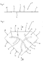
- eine perspektivische Ansicht einer Verwendung einer Duschablage gemäß einer ersten Ausführungsform der vorliegenden Erfindung;
- Figur 2
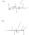
- eine Seitenansicht der Duschablage in Richtung des Pfeils II in Figur 1;
- Figur 3
- eine weitere Seitenansicht der Duschablage in Richtung des Pfeils III in
Figur 1 ; - Figur 4
- eine perspektivische Ansicht der in
Figur 1 dargestellten Duschablage während ihrer Installation; - Figur 5
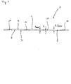
- eine Draufsicht einer Verwendung einer Duschablage gemäß einer zweiten Ausführungsform der vorliegenden Erfindung;
- Figur 6
- eine Seitenansicht in Richtung des Pfeils VI in
Figur 5 und - Figur 7
- eine weitere Seitenansicht in Richtung des Pfeils VII in
Figur 5 . - Nachfolgend beziehen sich gleiche Bezugsziffern auf gleiche oder gleichartige Bauteile bzw. Komponenten.
-
Figur 1 zeigt eine Duschablage 1 gemäß einer ersten Ausführungsform der vorliegenden Erfindung. Die Duschablage 1 umfasst ein Plattenelement 2 mit einer Unterseite 3, einer eine Ablagefläche bildenden Oberseite 4, die gemeinsam mit der Unterseite eine Plattenstärke S definiert, und vorliegend vier die Plattenoberseite 2 und die Plattenunterseite 3 miteinander verbindenden Stirnseiten 5, 6 , 7 und 8, wobei sich die Stirnseiten 5 und 6 senkrecht zueinander erstrecken. Das Plattenelement 2 ist einteilig aus einer Aluminium- oder Edelstahlplatte gefertigt. Die Plattenstärke S liegt bevorzugt im Bereich von 3 bis 6 mm. Sie ist vorliegend konstant und entspricht somit der maximalen Höhe Hmax der Duschablage 1. Das Plattenelement 2 ist mit mehreren sich von der Unterseite 3 zur Oberseite 4 erstreckenden Durchgangsöffnungen 9 versehen, die vorliegend aus optischen Gründen jeweils die Form eines Kreisbogensegmentes aufweisen. Alternativ können die Durchgangsöffnungen 9 aber auch jede andere Form haben. Das Plattenelement 2 weist an den beiden sich senkrecht zueinander erstreckenden Stirnseiten 5 und 6 Befestigungsvorsprünge 10 auf, die sich auswärts erstrecken und im Bereich der durch die Unterseite 3 und der Oberseite 4 aufgespannten Ebenen angeordnet sind, also nicht auf- oder abwärts über diese vorstehen. Die Befestigungsvorsprünge 10 weisen vorliegend eine Tiefe t im Bereich von 3 bis 10 mm, bevorzugt zwischen 4 und 8mm, und eine Höhe h im Bereich von 0,7 bis 2,5 mm auf und sind im Wesentlichen quaderförmig ausgebildet. Bei der dargestellten Ausführungsform sind an der Stirnseite 5 zwei Befestigungsvorsprünge 10 vorgesehen, die jeweils in den Endbereichen der Stirnseite 5 angeordnet sind. Die Stirnseite 6 weist lediglich einen einzelnen Befestigungsvorsprünge 10 auf, der im Endbereich der Stirnseite 6 benachbart zur Stirnseite 7 angeordnet ist. Die Anzahl der Befestigungsvorsprünge 10 ebenso wie deren Länge und/oder Form kann bedarfsgereicht variieren. Die Höhe h der Befestigungsvorsprünge 10 ist geringer als die Plattenstärke S. Vorliegend sind die Befestigungsvorsprünge 10, die benachbart zueinander an der Stirnseite 5 und an der Stirnseite 6 angeordnet sind, bündig mit der Unterseite 3 des Plattenelementes 2 angeordnet, während der verbleibende Befestigungsvorsprünge 10 benachbart zur Stirnseite 8 bündig mit der Oberseite 4 des Plattenelementes 2 abschließt. Dank dieser in Richtung der Plattenstärke S versetzten Anordnung der Plattenstärke S versetzten Anordnung der Befestigungsvorsprünge 10 wird bei der Montage der Duschablage 1 ein vorbestimmtes Gefälle der Oberseite 4 des Plattenelementes 2 zur Horizontalen eingestellt, worauf nachfolgend nochmals eingegangen wird. Die beiden sich senkrecht zueinander erstreckenden Stirnseiten 5 und 6 können über eine weitere Stirnseite 11 miteinander verbunden sein, deren Länge I bevorzugt zumindest 20 mm beträgt. Diese weitere Stirnseite 11 ist inFigur 1 durch eine gestrichelte Linie dargestellt. - Zur Installation der Duschablage 1 an zwei vertikalen, sich im Wesentlichen senkrecht zueinander erstreckenden, gemeinsam eine Ecke 12 bildenden, mit durch horizontale und vertikale Fugen 13 voneinander getrennten Fliesen 14 verkleideten Wänden 15 und 16 werden die Fliesen 14 in einem ersten Schritt in bekannter Weise an den Wänden 15 und 16 befestigt, beispielsweise unter Einsatz eines Dünnbettmörtels. Zwischen den Wänden 15 und 16 und den Fliesen 14 sollte vorab eine vorliegend nicht dargestellte Flächenabdichtung installiert werden. In einem weiteren Schritt werden die Fugen 13 mit einem Fugenmörtel verfugt. Unmittelbar nach dem Verfugen werden die Befestigungsvorsprünge 10 der Duschablage 1 in gewünschter Höhe in eine sich über den Eckbereich erstreckende horizontale Fuge 13 eingedrückt. Beim Erhärten des Fugenmörtels ist die Duschablage sicher an den Wänden 15 und 16 befestigt. Aufgrund der zuvor beschriebenen versetzten Anordnung der Befestigungsvorsprünge 10 in Richtung der Plattenstärke S wird während der Installation automatisch ein vorbestimmtes Gefälle der Oberseite 4 des Plattenelementes 2 zur Horizontalen eingestellt, wenn bei der Positionierung der Duschablage 1 sämtliche Befestigungsvorsprünge 10 entweder gegen obere Kanten der unteren Fliesen 14 oder gegen untere Kanten der oberen Fliesen 14 gedrückt werden. Sind die Stirnseiten 5 und 6 nicht durch die weitere Stirnseite 11 miteinander verbunden, so empfiehlt sich ein ausgehend von der Ecke 12 zur Dusche abfallendes Gefälle. Wird durch die weitere Stirnseite 11 hingegen eine Öffnung 17 zwischen der Duschablage 1 und den Wänden 15 und 16 gebildet, so kann das Gefälle auch umgekehrt abwärts in Richtung der Ecke 12 gewählt werden.
- Die
Figuren 5 bis 7 zeigen eine Duschablage 1 gemäß einer zweiten Ausführungsform der vorliegenden Erfindung. Diese unterscheidet sich dahingehend von der zuvor beschriebenen Duschablage, dass das Plattenelement 2 eine andere Form und daraus resultierend fünf Stirnseiten 5, 6, 7, 8 und 18 aufweist. Die Stirnseiten 5 und 6 erstrecken sich senkrecht zueinander und sind jeweils mit zwei Befestigungsvorsprüngen 10 versehen, die in Richtung der Plattenstärke S alle auf einem einheitlichen Niveau angeordnet sind. Entsprechend stellt sich bei der Installation der Duschablage 1 ein Gefälle bezüglich der Horizontalen nicht automatisch ein. Ein weiterer Unterschied besteht darin, dass Anzahl und Form der Durchgangsöffnungen 9 anders gewählt sind. - Es sei darauf hingewiesen, dass die zuvor beschriebenen Ausführungsformen der erfindungsgemäßen Verwendung einer Duschablage lediglich als Beispiele dienen und den durch die Ansprüche definierten Schutzbereich nicht einschränken.
-
- 1
- Duschablage
- 2
- Plattenelement
- 3
- Unterseite
- 4
- Oberseite
- 5
- Stirnseite
- 6
- Stirnseite
- 7
- Stirnseite
- 8
- Stirnseite
- 9
- Durchgangsöffnung
- 10
- Vorsprung
- 11
- Stirnseite
- 12
- Ecke
- 13
- Fuge
- 14
- Fliese
- 15
- Wand
- 16
- Wand
- 17
- Öffnung
- 18
- Stirnseite
- S
- Plattenstärke
- H
- Höhe
- h
- Höhe
- t
- Tiefe
- I
- Länge
Claims (9)
- Verwendung einerDuschablage (1), die zur Installation an zwei vertikalen, sich im Wesentlichen senkrecht zueinander erstreckenden, gemeinsam eine Ecke (12) bildenden, mit durch horizontale Fugen (13) voneinander getrennten Fliesen (14) verkleideten Wänden (15, 16) dient und ein flächiges, einteilig ausgebildetes Plattenelement (2) mit einer Unterseite (3), einer eine Ablagefläche bildenden Oberseite (4), die gemeinsam mit der Unterseite (3) eine Plattenstärke (S) definiert, und zumindest drei die Plattenunterseite (3) und die Plattenoberseite (4) miteinander verbindenden Stirnseiten (5, 6, 7, 8, 11, 18) aufweist, von denen sich zwei senkrecht zueinander erstrecken, wobei an den beiden sich senkrecht zueinander erstreckenden Stirnseiten (5, 6) einteilig mit diesen ausgebildete, auswärts vorstehende Befestigungsvorsprünge (10) vorgesehen sind, und wobei die maximale Gesamthöhe (Hmax) der Duschablage (1) der maximalen Plattenstärke (Smax) entspricht,derart, dass sämtliche Befestigungsvorsprünge (10) des Plattenelementes (2) in Fliesen (14) voneinander trennende, sich horizontal erstreckende Fugen (13) eingesetzt werden, die im rechten Winkel aufeinander treffen.
- Verwendung einer Duschablage (1) nach Anspruch 1, dadurch gekennzeichnet, dass die Höhe (h) der Befestigungsvorsprünge (10) im Bereich von 0,7 bis 2,5 mm liegt.
- Verwendung einer Duschablage (1) nach einem der vorhergehenden Ansprüche, dadurch gekennzeichnet, dass die Höhe (h) der Befestigungsvorsprünge (10) geringer als die Plattenstärke (S) ist.
- Verwendung einer Duschablage (1) nach einem der vorhergehenden Ansprüche, dadurch gekennzeichnet, dass die Plattenstärke (S) im Bereich von 3 bis 6 mm liegt.
- Verwendung einer Duschablage (1) nach einem der vorhergehenden Ansprüche, dadurch gekennzeichnet, dass an zumindest einer Stirnseite (5, 6) mehrere Befestigungsvorsprünge (10) vorgesehen sind.
- Verwendung einer Duschablage (1) nach Anspruch 5, dadurch gekennzeichnet, dass die jeweils an einer Stirnseite (5, 6) vorgesehenen Befestigungsvorsprünge (10) in Richtung der Plattenstärke (S) derart versetzt zueinander angeordnet sind, dass sich beim Einsetzen der Befestigungsvorsprünge (10) in an den Wänden (15, 16) angeordnete Fliesen (14) voneinander trennende, sich horizontal erstreckende Fugen (13) ein vorbestimmtes Gefälle der Oberseite (4) des Plattenelementes (2) zur Horizontalen einstellt.
- Verwendung einer Duschablage (1) nach einem der vorhergehenden Ansprüche, dadurch gekennzeichnet, dass die zwei sich senkrecht zueinander erstreckenden Stirnseiten (5, 6) über eine weitere Stirnseite (11) miteinander verbunden sind, deren Länge (I) bevorzugt zumindest 20mm beträgt.
- Verwendung einer Duschablage (1) nach einem der vorhergehenden Ansprüche, dadurch gekennzeichnet, dass das Plattenelement (2) mit sich von der Unterseite (3) zur Oberseite (4) erstreckenden Durchgangsöffnungen (9) versehen ist.
- Verwendung einer Duschablage (1) nach einem der vorhergehenden Ansprüche, dadurch gekennzeichnet, dass das Plattenelement (2) aus Edelstahl oder aus Aluminium hergestellt ist.
Priority Applications (1)
| Application Number | Priority Date | Filing Date | Title |
|---|---|---|---|
| PL19170885T PL3563738T3 (pl) | 2018-04-26 | 2019-04-24 | Półka prysznicowa |
Applications Claiming Priority (1)
| Application Number | Priority Date | Filing Date | Title |
|---|---|---|---|
| DE202018102357.8U DE202018102357U1 (de) | 2018-04-26 | 2018-04-26 | Duschablage |
Publications (2)
| Publication Number | Publication Date |
|---|---|
| EP3563738A1 EP3563738A1 (de) | 2019-11-06 |
| EP3563738B1 true EP3563738B1 (de) | 2021-12-15 |
Family
ID=66251707
Family Applications (1)
| Application Number | Title | Priority Date | Filing Date |
|---|---|---|---|
| EP19170885.8A Active EP3563738B1 (de) | 2018-04-26 | 2019-04-24 | Duschablage |
Country Status (7)
| Country | Link |
|---|---|
| US (1) | US20190335955A1 (de) |
| EP (1) | EP3563738B1 (de) |
| CA (1) | CA3041317A1 (de) |
| DE (1) | DE202018102357U1 (de) |
| ES (1) | ES2905125T3 (de) |
| PL (1) | PL3563738T3 (de) |
| PT (1) | PT3563738T (de) |
Families Citing this family (6)
| Publication number | Priority date | Publication date | Assignee | Title |
|---|---|---|---|---|
| US11653795B2 (en) * | 2019-10-27 | 2023-05-23 | Reyes Designs LLC | Supportive device for shelves, seats and steps in wet construction areas |
| USD1003631S1 (en) * | 2020-01-28 | 2023-11-07 | Schluter Systems L.P. | Shelf |
| USD1000865S1 (en) | 2020-01-28 | 2023-10-10 | Schluter Systems L.P. | Shelf |
| CA197113S (en) | 2020-01-28 | 2022-01-31 | Schluter Systems Canada Inc | Shelf |
| CA197112S (en) | 2020-01-28 | 2021-12-06 | Schluter Systems Canada Inc | Shelf |
| DE102020129030A1 (de) | 2020-11-04 | 2022-05-05 | Helge Schneider | Halterung zur aufbewahrung von behältern für produkte zur körperreinigung und/oder körperpflege |
Family Cites Families (9)
| Publication number | Priority date | Publication date | Assignee | Title |
|---|---|---|---|---|
| US2261078A (en) * | 1939-10-27 | 1941-10-28 | Franklin P Shockey | Shelf and mounting therefor |
| US5983805A (en) * | 1997-07-31 | 1999-11-16 | Waluda; Casey E. | Corner shelf assembly |
| US7621223B2 (en) * | 2007-10-05 | 2009-11-24 | Alireza Haghayegh | Corner shelf system |
| DE102012015574B4 (de) | 2012-08-08 | 2022-10-06 | Alexander Knoll sen. | Anordnung zur Befestigung einer Ablagevorrichtung sowie Ablagevorrichtung für eine derartige Anordnung |
| US8857109B1 (en) * | 2012-09-27 | 2014-10-14 | Mark E. Kirby | Tile-ready corner seat |
| DE102014110771A1 (de) * | 2014-07-30 | 2016-02-04 | Manuel Groß-Bölting | Kompakt bauende Duschablage |
| US9402476B2 (en) * | 2014-10-06 | 2016-08-02 | Brian Crandall | Shower shelf |
| CA2971407C (en) * | 2014-12-16 | 2021-06-01 | Ian STEFENACK | Platform mounting system and method |
| DE102016115677B4 (de) * | 2016-08-24 | 2018-11-22 | Guido Riebesam | Wandablage für Bad- oder Duschutensilien |
-
2018
- 2018-04-26 DE DE202018102357.8U patent/DE202018102357U1/de active Active
-
2019
- 2019-04-24 PL PL19170885T patent/PL3563738T3/pl unknown
- 2019-04-24 ES ES19170885T patent/ES2905125T3/es active Active
- 2019-04-24 US US16/393,625 patent/US20190335955A1/en not_active Abandoned
- 2019-04-24 PT PT191708858T patent/PT3563738T/pt unknown
- 2019-04-24 EP EP19170885.8A patent/EP3563738B1/de active Active
- 2019-04-26 CA CA3041317A patent/CA3041317A1/en active Pending
Also Published As
| Publication number | Publication date |
|---|---|
| CA3041317A1 (en) | 2019-10-26 |
| US20190335955A1 (en) | 2019-11-07 |
| ES2905125T3 (es) | 2022-04-07 |
| PL3563738T3 (pl) | 2022-05-02 |
| PT3563738T (pt) | 2022-01-20 |
| EP3563738A1 (de) | 2019-11-06 |
| DE202018102357U1 (de) | 2019-07-29 |
Similar Documents
| Publication | Publication Date | Title |
|---|---|---|
| EP3563738A1 (de) | Duschablage | |
| EP1294995B1 (de) | Fussbodensystem mit mehreren gleichen Fussbodenplatten | |
| DE69016091T2 (de) | Wandvertäfelungssystem. | |
| DE1658864A1 (de) | Dehnungsfugenabdeckung | |
| DE102015121810B4 (de) | Schalung für eine Aufkantung | |
| WO2004020764A1 (de) | Vorrichtung zum verbinden von zwei plattenförmigen paneelen | |
| DE2911094A1 (de) | Plattenverbindungssystem | |
| EP3536873B1 (de) | Profilelement, sowie fassadensystem mit dem profilelement | |
| DE69528972T2 (de) | Verkleidungsplatte | |
| DE60100600T2 (de) | Befestigungsvorrichtung für die längsränder von platten, latten oder wandverkleidungen mit kraftverteilung | |
| EP1961889B1 (de) | Befestigungsanordnung mit einem Aufnahmeprofil und einem Befestigungshaken | |
| DE3879497T2 (de) | Metallstuetze. | |
| WO2009006926A1 (de) | Wandpaneelkonzept 45° | |
| EP2957685B1 (de) | Verbindung zwischen wandelementen | |
| EP0629754A2 (de) | Gebäudewandverkleidung | |
| DE3490029T1 (de) | Schalungssystem | |
| EP4087984B1 (de) | System und verfahren zum errichten von gebäudewänden, -decken und/oder -dächern | |
| DE3332623A1 (de) | Fassadenverkleidung | |
| DE2900517C2 (de) | Filter mit mehreren Zellen für körnigen Filterstoff | |
| DE202018105849U1 (de) | Schnallenaufbau zum Montieren einer Speicher-Leiterplatte | |
| DE2425432C3 (de) | Nichttragende Gebäudetrennwand | |
| DE9201477U1 (de) | Fassadenschindel | |
| DE8603355U1 (de) | Verschalungsrahmen für einen Wand- oder Deckendurchbruch | |
| DE202020104085U1 (de) | Bauelementsystem | |
| EP0071832A2 (de) | Futtertrogeinrichtung |
Legal Events
| Date | Code | Title | Description |
|---|---|---|---|
| PUAI | Public reference made under article 153(3) epc to a published international application that has entered the european phase |
Free format text: ORIGINAL CODE: 0009012 |
|
| STAA | Information on the status of an ep patent application or granted ep patent |
Free format text: STATUS: THE APPLICATION HAS BEEN PUBLISHED |
|
| AK | Designated contracting states |
Kind code of ref document: A1 Designated state(s): AL AT BE BG CH CY CZ DE DK EE ES FI FR GB GR HR HU IE IS IT LI LT LU LV MC MK MT NL NO PL PT RO RS SE SI SK SM TR |
|
| AX | Request for extension of the european patent |
Extension state: BA ME |
|
| STAA | Information on the status of an ep patent application or granted ep patent |
Free format text: STATUS: REQUEST FOR EXAMINATION WAS MADE |
|
| 17P | Request for examination filed |
Effective date: 20191114 |
|
| RBV | Designated contracting states (corrected) |
Designated state(s): AL AT BE BG CH CY CZ DE DK EE ES FI FR GB GR HR HU IE IS IT LI LT LU LV MC MK MT NL NO PL PT RO RS SE SI SK SM TR |
|
| GRAP | Despatch of communication of intention to grant a patent |
Free format text: ORIGINAL CODE: EPIDOSNIGR1 |
|
| STAA | Information on the status of an ep patent application or granted ep patent |
Free format text: STATUS: GRANT OF PATENT IS INTENDED |
|
| INTG | Intention to grant announced |
Effective date: 20210810 |
|
| GRAS | Grant fee paid |
Free format text: ORIGINAL CODE: EPIDOSNIGR3 |
|
| GRAA | (expected) grant |
Free format text: ORIGINAL CODE: 0009210 |
|
| STAA | Information on the status of an ep patent application or granted ep patent |
Free format text: STATUS: THE PATENT HAS BEEN GRANTED |
|
| AK | Designated contracting states |
Kind code of ref document: B1 Designated state(s): AL AT BE BG CH CY CZ DE DK EE ES FI FR GB GR HR HU IE IS IT LI LT LU LV MC MK MT NL NO PL PT RO RS SE SI SK SM TR |
|
| REG | Reference to a national code |
Ref country code: GB Ref legal event code: FG4D Free format text: NOT ENGLISH Ref country code: CH Ref legal event code: EP |
|
| REG | Reference to a national code |
Ref country code: DE Ref legal event code: R096 Ref document number: 502019002984 Country of ref document: DE |
|
| REG | Reference to a national code |
Ref country code: IE Ref legal event code: FG4D Free format text: LANGUAGE OF EP DOCUMENT: GERMAN |
|
| REG | Reference to a national code |
Ref country code: AT Ref legal event code: REF Ref document number: 1454833 Country of ref document: AT Kind code of ref document: T Effective date: 20220115 |
|
| REG | Reference to a national code |
Ref country code: NL Ref legal event code: FP |
|
| REG | Reference to a national code |
Ref country code: PT Ref legal event code: SC4A Ref document number: 3563738 Country of ref document: PT Date of ref document: 20220120 Kind code of ref document: T Free format text: AVAILABILITY OF NATIONAL TRANSLATION Effective date: 20220112 |
|
| REG | Reference to a national code |
Ref country code: ES Ref legal event code: FG2A Ref document number: 2905125 Country of ref document: ES Kind code of ref document: T3 Effective date: 20220407 |
|
| REG | Reference to a national code |
Ref country code: LT Ref legal event code: MG9D |
|
| PG25 | Lapsed in a contracting state [announced via postgrant information from national office to epo] |
Ref country code: RS Free format text: LAPSE BECAUSE OF FAILURE TO SUBMIT A TRANSLATION OF THE DESCRIPTION OR TO PAY THE FEE WITHIN THE PRESCRIBED TIME-LIMIT Effective date: 20211215 Ref country code: LT Free format text: LAPSE BECAUSE OF FAILURE TO SUBMIT A TRANSLATION OF THE DESCRIPTION OR TO PAY THE FEE WITHIN THE PRESCRIBED TIME-LIMIT Effective date: 20211215 Ref country code: FI Free format text: LAPSE BECAUSE OF FAILURE TO SUBMIT A TRANSLATION OF THE DESCRIPTION OR TO PAY THE FEE WITHIN THE PRESCRIBED TIME-LIMIT Effective date: 20211215 Ref country code: BG Free format text: LAPSE BECAUSE OF FAILURE TO SUBMIT A TRANSLATION OF THE DESCRIPTION OR TO PAY THE FEE WITHIN THE PRESCRIBED TIME-LIMIT Effective date: 20220315 |
|
| PG25 | Lapsed in a contracting state [announced via postgrant information from national office to epo] |
Ref country code: SE Free format text: LAPSE BECAUSE OF FAILURE TO SUBMIT A TRANSLATION OF THE DESCRIPTION OR TO PAY THE FEE WITHIN THE PRESCRIBED TIME-LIMIT Effective date: 20211215 Ref country code: NO Free format text: LAPSE BECAUSE OF FAILURE TO SUBMIT A TRANSLATION OF THE DESCRIPTION OR TO PAY THE FEE WITHIN THE PRESCRIBED TIME-LIMIT Effective date: 20220315 Ref country code: LV Free format text: LAPSE BECAUSE OF FAILURE TO SUBMIT A TRANSLATION OF THE DESCRIPTION OR TO PAY THE FEE WITHIN THE PRESCRIBED TIME-LIMIT Effective date: 20211215 Ref country code: HR Free format text: LAPSE BECAUSE OF FAILURE TO SUBMIT A TRANSLATION OF THE DESCRIPTION OR TO PAY THE FEE WITHIN THE PRESCRIBED TIME-LIMIT Effective date: 20211215 Ref country code: GR Free format text: LAPSE BECAUSE OF FAILURE TO SUBMIT A TRANSLATION OF THE DESCRIPTION OR TO PAY THE FEE WITHIN THE PRESCRIBED TIME-LIMIT Effective date: 20220316 |
|
| PG25 | Lapsed in a contracting state [announced via postgrant information from national office to epo] |
Ref country code: SM Free format text: LAPSE BECAUSE OF FAILURE TO SUBMIT A TRANSLATION OF THE DESCRIPTION OR TO PAY THE FEE WITHIN THE PRESCRIBED TIME-LIMIT Effective date: 20211215 Ref country code: SK Free format text: LAPSE BECAUSE OF FAILURE TO SUBMIT A TRANSLATION OF THE DESCRIPTION OR TO PAY THE FEE WITHIN THE PRESCRIBED TIME-LIMIT Effective date: 20211215 Ref country code: RO Free format text: LAPSE BECAUSE OF FAILURE TO SUBMIT A TRANSLATION OF THE DESCRIPTION OR TO PAY THE FEE WITHIN THE PRESCRIBED TIME-LIMIT Effective date: 20211215 Ref country code: EE Free format text: LAPSE BECAUSE OF FAILURE TO SUBMIT A TRANSLATION OF THE DESCRIPTION OR TO PAY THE FEE WITHIN THE PRESCRIBED TIME-LIMIT Effective date: 20211215 |
|
| REG | Reference to a national code |
Ref country code: DE Ref legal event code: R097 Ref document number: 502019002984 Country of ref document: DE |
|
| PG25 | Lapsed in a contracting state [announced via postgrant information from national office to epo] |
Ref country code: IS Free format text: LAPSE BECAUSE OF FAILURE TO SUBMIT A TRANSLATION OF THE DESCRIPTION OR TO PAY THE FEE WITHIN THE PRESCRIBED TIME-LIMIT Effective date: 20220415 |
|
| PLBE | No opposition filed within time limit |
Free format text: ORIGINAL CODE: 0009261 |
|
| STAA | Information on the status of an ep patent application or granted ep patent |
Free format text: STATUS: NO OPPOSITION FILED WITHIN TIME LIMIT |
|
| PG25 | Lapsed in a contracting state [announced via postgrant information from national office to epo] |
Ref country code: DK Free format text: LAPSE BECAUSE OF FAILURE TO SUBMIT A TRANSLATION OF THE DESCRIPTION OR TO PAY THE FEE WITHIN THE PRESCRIBED TIME-LIMIT Effective date: 20211215 Ref country code: AL Free format text: LAPSE BECAUSE OF FAILURE TO SUBMIT A TRANSLATION OF THE DESCRIPTION OR TO PAY THE FEE WITHIN THE PRESCRIBED TIME-LIMIT Effective date: 20211215 |
|
| 26N | No opposition filed |
Effective date: 20220916 |
|
| PG25 | Lapsed in a contracting state [announced via postgrant information from national office to epo] |
Ref country code: SI Free format text: LAPSE BECAUSE OF FAILURE TO SUBMIT A TRANSLATION OF THE DESCRIPTION OR TO PAY THE FEE WITHIN THE PRESCRIBED TIME-LIMIT Effective date: 20211215 |
|
| REG | Reference to a national code |
Ref country code: CH Ref legal event code: PL |
|
| PG25 | Lapsed in a contracting state [announced via postgrant information from national office to epo] |
Ref country code: MC Free format text: LAPSE BECAUSE OF FAILURE TO SUBMIT A TRANSLATION OF THE DESCRIPTION OR TO PAY THE FEE WITHIN THE PRESCRIBED TIME-LIMIT Effective date: 20211215 Ref country code: LU Free format text: LAPSE BECAUSE OF NON-PAYMENT OF DUE FEES Effective date: 20220424 Ref country code: LI Free format text: LAPSE BECAUSE OF NON-PAYMENT OF DUE FEES Effective date: 20220430 Ref country code: CH Free format text: LAPSE BECAUSE OF NON-PAYMENT OF DUE FEES Effective date: 20220430 |
|
| PG25 | Lapsed in a contracting state [announced via postgrant information from national office to epo] |
Ref country code: LI Free format text: LAPSE BECAUSE OF NON-PAYMENT OF DUE FEES Effective date: 20220430 Ref country code: CH Free format text: LAPSE BECAUSE OF NON-PAYMENT OF DUE FEES Effective date: 20220430 |
|
| PGRI | Patent reinstated in contracting state [announced from national office to epo] |
Ref country code: LI Effective date: 20230119 Ref country code: CH Effective date: 20230119 |
|
| P01 | Opt-out of the competence of the unified patent court (upc) registered |
Effective date: 20230516 |
|
| PG25 | Lapsed in a contracting state [announced via postgrant information from national office to epo] |
Ref country code: HU Free format text: LAPSE BECAUSE OF FAILURE TO SUBMIT A TRANSLATION OF THE DESCRIPTION OR TO PAY THE FEE WITHIN THE PRESCRIBED TIME-LIMIT; INVALID AB INITIO Effective date: 20190424 |
|
| PG25 | Lapsed in a contracting state [announced via postgrant information from national office to epo] |
Ref country code: MK Free format text: LAPSE BECAUSE OF FAILURE TO SUBMIT A TRANSLATION OF THE DESCRIPTION OR TO PAY THE FEE WITHIN THE PRESCRIBED TIME-LIMIT Effective date: 20211215 Ref country code: CY Free format text: LAPSE BECAUSE OF FAILURE TO SUBMIT A TRANSLATION OF THE DESCRIPTION OR TO PAY THE FEE WITHIN THE PRESCRIBED TIME-LIMIT Effective date: 20211215 |
|
| PG25 | Lapsed in a contracting state [announced via postgrant information from national office to epo] |
Ref country code: MT Free format text: LAPSE BECAUSE OF FAILURE TO SUBMIT A TRANSLATION OF THE DESCRIPTION OR TO PAY THE FEE WITHIN THE PRESCRIBED TIME-LIMIT Effective date: 20211215 |
|
| PGFP | Annual fee paid to national office [announced via postgrant information from national office to epo] |
Ref country code: NL Payment date: 20250422 Year of fee payment: 7 |
|
| PGFP | Annual fee paid to national office [announced via postgrant information from national office to epo] |
Ref country code: PL Payment date: 20250411 Year of fee payment: 7 Ref country code: DE Payment date: 20250205 Year of fee payment: 7 |
|
| PGFP | Annual fee paid to national office [announced via postgrant information from national office to epo] |
Ref country code: ES Payment date: 20250519 Year of fee payment: 7 |
|
| PGFP | Annual fee paid to national office [announced via postgrant information from national office to epo] |
Ref country code: IT Payment date: 20250430 Year of fee payment: 7 Ref country code: BE Payment date: 20250422 Year of fee payment: 7 |
|
| PGFP | Annual fee paid to national office [announced via postgrant information from national office to epo] |
Ref country code: PT Payment date: 20250417 Year of fee payment: 7 |
|
| PGFP | Annual fee paid to national office [announced via postgrant information from national office to epo] |
Ref country code: FR Payment date: 20250428 Year of fee payment: 7 |
|
| PGFP | Annual fee paid to national office [announced via postgrant information from national office to epo] |
Ref country code: CH Payment date: 20250501 Year of fee payment: 7 |
|
| PGFP | Annual fee paid to national office [announced via postgrant information from national office to epo] |
Ref country code: AT Payment date: 20250416 Year of fee payment: 7 |
|
| PGFP | Annual fee paid to national office [announced via postgrant information from national office to epo] |
Ref country code: TR Payment date: 20250417 Year of fee payment: 7 |
|
| PGFP | Annual fee paid to national office [announced via postgrant information from national office to epo] |
Ref country code: CZ Payment date: 20250411 Year of fee payment: 7 |
|
| PGFP | Annual fee paid to national office [announced via postgrant information from national office to epo] |
Ref country code: IE Payment date: 20250428 Year of fee payment: 7 |
|
| PGFP | Annual fee paid to national office [announced via postgrant information from national office to epo] |
Ref country code: GB Payment date: 20260224 Year of fee payment: 8 |
|
| REG | Reference to a national code |
Ref country code: CH Ref legal event code: U11 Free format text: ST27 STATUS EVENT CODE: U-0-0-U10-U11 (AS PROVIDED BY THE NATIONAL OFFICE) Effective date: 20260501 |