EP3563982A1 - Système de montage destiné au montage sur une pince aspirante élastique déformables et actionneur mécanique - Google Patents
Système de montage destiné au montage sur une pince aspirante élastique déformables et actionneur mécanique Download PDFInfo
- Publication number
- EP3563982A1 EP3563982A1 EP18170738.1A EP18170738A EP3563982A1 EP 3563982 A1 EP3563982 A1 EP 3563982A1 EP 18170738 A EP18170738 A EP 18170738A EP 3563982 A1 EP3563982 A1 EP 3563982A1
- Authority
- EP
- European Patent Office
- Prior art keywords
- suction
- bellows
- mounting
- longitudinal axis
- suction gripper
- Prior art date
- Legal status (The legal status is an assumption and is not a legal conclusion. Google has not performed a legal analysis and makes no representation as to the accuracy of the status listed.)
- Withdrawn
Links
Images


Classifications
-
- B—PERFORMING OPERATIONS; TRANSPORTING
- B25—HAND TOOLS; PORTABLE POWER-DRIVEN TOOLS; MANIPULATORS
- B25J—MANIPULATORS; CHAMBERS PROVIDED WITH MANIPULATION DEVICES
- B25J9/00—Program-controlled manipulators
- B25J9/08—Program-controlled manipulators characterised by modular constructions
-
- B—PERFORMING OPERATIONS; TRANSPORTING
- B25—HAND TOOLS; PORTABLE POWER-DRIVEN TOOLS; MANIPULATORS
- B25J—MANIPULATORS; CHAMBERS PROVIDED WITH MANIPULATION DEVICES
- B25J15/00—Gripping heads and other end effectors
- B25J15/0023—Gripper surfaces directly activated by a fluid
-
- B—PERFORMING OPERATIONS; TRANSPORTING
- B25—HAND TOOLS; PORTABLE POWER-DRIVEN TOOLS; MANIPULATORS
- B25J—MANIPULATORS; CHAMBERS PROVIDED WITH MANIPULATION DEVICES
- B25J15/00—Gripping heads and other end effectors
- B25J15/04—Gripping heads and other end effectors with provision for the remote detachment or exchange of the head or parts thereof
- B25J15/0475—Exchangeable fingers
-
- B—PERFORMING OPERATIONS; TRANSPORTING
- B25—HAND TOOLS; PORTABLE POWER-DRIVEN TOOLS; MANIPULATORS
- B25J—MANIPULATORS; CHAMBERS PROVIDED WITH MANIPULATION DEVICES
- B25J15/00—Gripping heads and other end effectors
- B25J15/06—Gripping heads and other end effectors with vacuum or magnetic holding means
- B25J15/0616—Gripping heads and other end effectors with vacuum or magnetic holding means with vacuum
-
- B—PERFORMING OPERATIONS; TRANSPORTING
- B25—HAND TOOLS; PORTABLE POWER-DRIVEN TOOLS; MANIPULATORS
- B25J—MANIPULATORS; CHAMBERS PROVIDED WITH MANIPULATION DEVICES
- B25J15/00—Gripping heads and other end effectors
- B25J15/08—Gripping heads and other end effectors having finger members
- B25J15/12—Gripping heads and other end effectors having finger members with flexible finger members
-
- B—PERFORMING OPERATIONS; TRANSPORTING
- B25—HAND TOOLS; PORTABLE POWER-DRIVEN TOOLS; MANIPULATORS
- B25J—MANIPULATORS; CHAMBERS PROVIDED WITH MANIPULATION DEVICES
- B25J9/00—Program-controlled manipulators
- B25J9/10—Program-controlled manipulators characterised by positioning means for manipulator elements
- B25J9/14—Program-controlled manipulators characterised by positioning means for manipulator elements fluid
- B25J9/142—Program-controlled manipulators characterised by positioning means for manipulator elements fluid comprising inflatable bodies
Definitions
- the invention relates to a mounting arrangement for mounting on elastically deformable suction pads and a operated with pressurized fluid, mechanical actuator.
- pressure-operated (or pressure-fluid-driven) actuators offer some advantages. For example, with suction grippers, a variety of object types can be reliably and gently manipulated (i.e., gripped, relocated, etc.). The necessary facilities for pressure-driven handling devices are well developed and reliable.
- the present invention has for its object to build from conventional suction pads a mechanical actuator in an easy mountable, reliable and cost-effective manner.
- the mounting arrangement is for attachment to elastically deformable suction pads.
- Such suction pads typically have a first end and a second end and a bellows between the first and second ends.
- the bellows extends around a longitudinal axis bellows, and is formed in particular bellows.
- the bellows is compressible starting from a rest position along its longitudinal axis.
- the bellows surrounds a bellows interior, which is compressed when subjected to negative pressure, i. contracts along the longitudinal axis (provided that the suction side is sealed, e.g., by abutting against a surface to be suctioned).
- the attachment assembly includes an upper linkage unit configured to receive the first end or the second end of a first vacuum gripper with the unaccounted end released from the upper linkage unit.
- the attachment assembly also includes a lower linkage unit adapted to receive the first end or the second end of another suction pad, again with the unaccounted end released from the lower linkage unit.
- the arrangement further comprises a receptacle into which the end of the first suction gripper not received in the upper connection unit (ie the released end of the first suction gripper) and the end of the further suction gripper not received in the lower connection unit (ie the free end of the further suction gripper) is recorded.
- the picture is in particular designed such that the bellows interior of the first suction pad with the bellows interior of the further suction pad sealingly connected to an entire bellows interior for both bellows is connected.
- the mounting arrangement also comprises a restoring element, which is mechanically connected to the upper connection unit and with the lower connection unit.
- the restoring element is designed and arranged such that it restricts a compression of the bellows of the first suction gripper and of the further suction gripper asymmetrically with respect to the respective longitudinal axis.
- the compressibility of the bellows is restricted in those areas in which the restoring element acts in comparison to the remaining areas of the bellows which are not influenced by the restoring element.
- the restoring element in the assembled state of add-on element and suction gripper acts in such a way that the suction grippers are asymmetrically compressible with respect to their respective longitudinal axis.
- the bellows Since the return element acts asymmetrically with respect to the longitudinal axis, the bellows is no longer compressed substantially symmetrically and axially along the longitudinal axis upon application of a bellows interior with negative pressure, but contracts asymmetrically with respect to the longitudinal axis. As a result, the bellows bends in compression in the lateral direction with respect to the longitudinal axis, that is, there is a lateral deflection. Due to this lateral deflection, the overall arrangement of mounting arrangement with suction pads can act as a mechanical actuator to exert forces by mechanical contact with objects. In particular, it is provided that the overall arrangement (Mounting arrangement including built-in suction pads) is arranged on a base, and forms a kind of gripping finger.
- suction pads can be used with the parts of the mounting arrangement which are designed as standard suction grippers (for example with bellows).
- the attachment units may e.g. be formed by standard connectors or conventional clamps or brackets.
- a mechanical actuator can be inexpensively provided from components that are also used in vacuum handling systems.
- the receptacle is preferably arranged between the upper nozzle connection and the lower nozzle connection.
- the mounting arrangement may be adapted to be mounted on a group of more than two suction pads, wherein the suction pads are lined up along their longitudinal axes.
- two adjacent suction pads are connected in the manner described.
- suction pads are used whose bellows has a rotationally symmetrical cross-section about the longitudinal axis. Without the action of the return element such a suction pad would contract symmetrically along the longitudinal axis when its bellows interior is subjected to negative pressure. Due to the action of the return element, as explained, an asymmetric compression is accompanied by a lateral deflection of the overall arrangement.
- connection unit and / or the receptacle are preferably designed such that the mounting arrangement is fixed against rotation about the suction pads.
- the upper connection unit, the lower connection unit, the receptacle and the return element are designed to be arranged in each case outside the bellows (that is to say on the side of the bellows facing away from the bellows interior) of the first and further suction grippers.
- the mounting arrangement is designed for outdoor attachment to suction pads. It is attached in the manner of an outer corset to the bellows of the two suction pads. By this cultivation from outside the bellows interior is not affected. Thus, it can be avoided to insert or push components into the interior of the bellows. An attachment from the outside to the bellows simplifies the assembly.
- the restoring element can extend from the upper connecting unit to the lower connecting unit and thereby extend itself asymmetrically with respect to the longitudinal axis.
- the return element is offset laterally offset to the longitudinal axis.
- the restoring element is in particular not formed axis-symmetrical to the longitudinal axis of the first and / or further suction gripper.
- the components of the mounting arrangement are preferably arranged such that the longitudinal axes of the first and the further suction pads are aligned with each other, when the suction pads are in an uncompressed resting position.
- the return element may also be mechanically connected to the receptacle.
- suction pads are used, which have as a first end an end piece for connection to a vacuum supply, wherein the second end is formed as a suction side, which is provided with a particular circumferential sealing lip for abutment against a surface to be sucked.
- connection units are then designed and arranged in such a way that the two inserted suction pads face each other upside down.
- the upper or lower connection unit thus preferably forms an upper or lower nozzle connection.
- the end of the first suction cup is receivable.
- the end of the other suction gripper is accommodated such that the sealing lip of the further suction pad of the sealing lip of the first suction pad faces.
- the receptacle is designed as a lip socket, in which the sealing lip of the first suction pad and the sealing lip of the further suction pad is sealingly receivable.
- the sealing lips of the two suction pads facing each other.
- the Sealing lips are received in the lip socket so that the bellows interior of the first suction pad with the bellows interior of the other suction pads sealingly connected to an entire bellows interior for both bellows.
- the sealing lips of the two suction pads sealingly abut each other in the installed state.
- the lip socket preferably has a first clamping portion and a second clamping portion.
- the sealing lips of the two suckers can then preferably be clamped between the two clamping sections, in particular in such a way that the sealing lips abut one another directly.
- the two clamping sections preferably have latching elements which can be latched into one another.
- latching elements which can be latched into one another.
- snap-in hooks may be provided on the first clamping section and on the second clamping section, which snap-in hooks on assigned areas of the respective other clamping section.
- the return element acts such that it exerts a restoring force against deformation from a rest position.
- the restoring element and - if installed - the suction pads in particular a configuration in which the entire arrangement extends along the longitudinal axes.
- the restoring element is elastically deformable starting from the rest position.
- the return element causes a re-deformation of the overall arrangement (mounting arrangement with built-in suction pads), if no action is taken on the bellows with negative pressure.
- the deflection movement of the mechanical Actuators including mounting arrangement with built-in suction pads
- the return movement is then passive due to the restoring force of the return element.
- the restoring element is in particular designed such that - in the installed state - the bellows of the suction pads extend in the presence of the rest position straight along the respective longitudinal axes.
- the return element may be formed as a resiliently flexible spring element.
- the mounting arrangement is then designed in particular such that a deformation from the rest position is connected to a lateral bending of the spring element.
- the reset element may e.g. as a simple spring band, e.g. Metal strip, be formed.
- the restoring element is designed as elastically extensible and / or elastically compressible spring element.
- the mounting arrangement is in particular designed such that a deformation from the rest position is associated with a longitudinal expansion and / or a longitudinal compression of the spring element.
- a spring element can be formed in a simple manner from a section of a conventional hose (for example made of rubber, plastic).
- a return element of the type mentioned can be provided, for example, by an elastic pressure hose. This pressure hose can then also serve to provide a suction gripping element provided at the lower nozzle connection To supply negative pressure, as described in more detail below.
- the restoring element has a mold section which is designed such that the mold section fills some or all folds of the bellows-shaped bellows in a defined and restricted area of the circumference of the bellows about the longitudinal axis.
- the mold portion is preferably formed of an elastically compressible material.
- the mold portion is formed such that it fills only a certain angle sector around the longitudinal axis.
- the molding section is particularly formed as a pleat engagement section for engaging in pleats of the bellows, i. in particular, the mold section comprises a plurality of projections which lie next to one another along the longitudinal axis and are designed such that they can engage in folds of the bellows.
- the mounting arrangement is preferably modular. In principle, different sections can be combined into units.
- the receptacle has an upper socket portion and a lower socket portion, wherein the upper and the lower socket portion can be joined together and receive the not taken in the upper and lower connection unit ends (ie, the released ends) of the suction pads during assembly.
- This is particularly advantageous in the described embodiment with sealing lips, wherein the mutually facing sealing lips of the two suction pads are clamped between the upper socket portion and the lower socket portion.
- the return element accordingly comprises an upper spring part and a lower spring part.
- the upper socket portion and the upper spring member and the upper link unit are designed as a one-piece component.
- the lower socket portion and the lower spring member and the lower link unit can be integrally connected to each other.
- the mounting arrangement can be provided by two of said one-piece composite units, which facilitates the assembly.
- the mounting arrangement comprises a lower end element. This is adapted to be arranged on the lower connection unit and / or on the recorded in the lower connection unit end of the other suction pads.
- the lower end element is arranged on the end of the further suction gripper.
- the lower end element in particular provides a mechanical contact surface.
- This gripping surface is intended to come into mechanical contact with an object to be manipulated when the overall arrangement (mounting arrangement with inserted suction pads) acts as a mechanical actuator.
- This provides the functionality of a gripper finger.
- the contact surface of the end element acts insofar as gripping jaw.
- friction structures, fins or the like can be provided on the contact surface. It is also conceivable that the contact surface is asymmetrical (in particular not rotationally symmetrical with respect to the Longitudinal axis) is configured and provides a directional gripping surface.
- the lower end member is preferably formed such that the bellows interior enclosed by the bellows is sealed at the end stub (i.e., downwardly).
- an upper terminating element may be provided, e.g. as a connecting element or nipple for vacuum supply.
- the lower end element may have a suction gripping element for sucking an object to be gripped.
- the overall arrangement mounting arrangement with inserted suction pads
- the overall arrangement then acts as a mechanical actuator, which additionally applies a gripping force by suction on contact with an object to be manipulated.
- a supply channel for supplying the suction gripping element is provided with negative pressure.
- This supply channel can be integrated in an advantageous manner in the return element and / or be formed in the return element itself. It is also conceivable that the restoring element is provided in total by an elastic pressure hose, which provides the supply channel. This is a particularly cost-effective solution with standard components.
- the lower end element and / or the return element may have sensor elements (eg pressure sensor and / or proximity sensor and / or force sensor). Likewise, sensor elements may be provided in the upper and / or lower connection unit. This can eg be monitored whether and to what extent the overall assembly is bent laterally (deflection control, gripping control), or whether an object is in contact with the mechanical actuator. If the mechanical actuator is designed as a gripper, the holding force can be detected. Possible cable connections for the sensors can be arranged in an advantageous manner in or on the return element. This results in less cabling and the overall arrangement is robust and prone to errors.
- sensor elements eg pressure sensor and / or proximity sensor and / or force sensor.
- sensor elements may be provided in the upper and / or lower connection unit. This can eg be monitored whether and to what extent the overall assembly is bent laterally (deflection control, gripping control), or whether an object is in contact with the mechanical actuator. If the mechanical actuator is designed as a gripper, the holding force can be detected. Possible cable connections
- the object stated in the introduction is also achieved by a mechanical actuator operable with pressurized fluid, in particular compressed air and / or negative pressure.
- the mechanical actuator then comprises a first and a further suction gripper of the type mentioned and an attachment arrangement with the features described above.
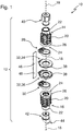
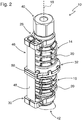
- FIGS. 1 and 2 show a mechanical actuator 10 comprising a multi-part mounting assembly 12 which is attached to a first suction pad 14 and a further suction pad 16 (see. FIG. 2 ).
- the suction pads 14 and 16 may be formed as standard Faltenbalgsauger.
- the suction pads 14, 16 each include a bellows 20 extending around a longitudinal axis 18 (here: bellows), a first end 22 and a second end 24.
- the first end is designed as an end piece 22 and the second end forms a suction side 24 with sealing lip 26.
- such suction pads are connected via their end pipe 22 to a vacuum supply and attached to the suction side 24 to a surface to be sucked (an object to be gripped). If the suction gripper is subjected to negative pressure, then the bellows 20 contracts symmetrically along the longitudinal axis 18 (not shown).
- the mounting assembly 12 is modular and includes in particular an upper connection unit in the form of an upper nozzle connection 28, a lower connection unit in the form of a lower nozzle connection 30 and a lip socket 32 (recording 32).
- the lip socket can in turn be constructed in several parts and e.g. a first clamping portion 34 and a second clamping portion 36 include.
- the mounting assembly 12, in particular the above-mentioned components are grown from the outside to the suction pads 14, 16.
- the upper nozzle connection 28 is mechanically connected to the end pipe 22 of the first suction pad 14.
- the upper nozzle connection 28 is clamped around the end fitting 22 and secured, e.g. screwed.
- the lower nozzle connection 30 may be designed accordingly, but this is not mandatory.
- the lip socket 32 is designed in such a way that the sealing lip 26 of the first suction pad 14 and the sealing lip 26 of the further suction pad 16 can be received in the lip socket.
- the Sealing lips 26 received so that they rest sealingly against each other.
- the sealing lips 26 of the suction pads 14 and 16 may be clamped against each other between the first clamping portion 34 and the second clamping portion 36 of the lip socket 32.
- the clamping portions 34, 36 of the lip socket 32 can for this purpose in particular latching portions 38, for example in the form of clamping lugs have. These locking portions 38 engage with each other, so that the clamping portions 34 and 36 form an assembled unit and the sealing lips 26 are accommodated in the unit.
- the attachment assembly 12 may also include an upper end member 40 which is inserted into the end fitting 22 of the first suction pad 14 and is used e.g. for connection to a vacuum supply (nipple).
- a lower end element 42 may be provided for the lower suction gripper 16. This can, as in FIGS. 1 and 2 sketched to be configured to be inserted into the end 22 of the further suction pad 16. It is also conceivable, however, that the lower end element 42 is mechanically connectable to the lower nozzle connection 30.
- the lower end element 42 preferably has a mechanical contact surface 44, which serves as a contact surface for the objects to be manipulated with the actuator during operation of the mechanical actuator 10. In the example of FIGS. 1 and 2 is the mechanical contact surface 44 asymmetric with respect to the longitudinal axis 18 and act insofar direction bound.
- the mounting assembly 12 includes a return element 46 which is mechanically connected to the upper nozzle connection 28 and with the lower nozzle connection 30.
- the restoring element 48 may be formed as a spring-deflectable spring element, in particular leaf spring 48.
- the return element 46 has the function that for the suction pads 14 and 16, when installed in the mounting assembly 12, the compressibility of the bellows 20 is limited asymmetrically with respect to the respective longitudinal axis 18.
- the restoring element 46 is arranged offset laterally relative to the longitudinal axis 18 (cf. FIG. 2 ).
- the upper nozzle connection 28 and the lower nozzle connection 30 can respectively receive end sections of the spring element 48 and fix them offset axially relative to the longitudinal axis 18 (FIG. FIG. 2 ).
- the lip socket 32 may also be connected to the return element 46.
- the spring element 48 is passed through a corresponding passage 50 in the lip socket 32.
- the mechanical actuator 10 is acted upon by the upper connection element 40 with negative pressure, a compression of the bellows 20 is caused.
- the return member 46 acts asymmetrically with respect to the longitudinal axis 18, the compression of the bellows 20 can not be asymmetric with respect to the longitudinal axis 18. Rather, the mechanical actuator 10 bends to the side facing away from the return element 46 (see also FIGS. 8 and 9 ).
- the spring element 48 is based on the in FIG. 2 shown rest position in which the spring element 48 straight extends, laterally bendable. Due to its elastic properties, the spring element exerts a restoring force against deformation from the rest position. This restoring force can be used to return the mechanical actuator 10 back to its initial configuration.
- the modular design of the mounting assembly 12 allows a variety of different configurations for the individual components, in particular for the return element 46th
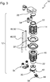
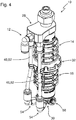
- the return element 46 may be formed as elastically extensible and / or elastically compressible spring element, for example in the form of elastically stretchable pressure hoses 52.
- the pressure hoses 52 are connected on the one hand with the upper nozzle connection 28, on the other hand with the lower nozzle connection 30.
- the upper nozzle connection 28 on the other hand with the lower nozzle connection 30.
- the lower nozzle connection 30 for this standard components can be used.
- the upper nozzle connection 28 is designed as an insertion part, which is inserted into the end piece 22 of the first suction pad 14 and at the same time provides the connection to the vacuum supply.
- the upper nozzle connection 28 have corresponding connections for hose connectors 54 into which the pressure hoses 52 can be enclosed.
- the lower nozzle connection has in particular corresponding interfaces for hose connector 54, in which the opposite ends of the pressure hoses 52 are received.
- the pressure hoses 52 are in turn mechanically connected to the upper nozzle connection 28 and the lower nozzle connection 30 and act as a return element 46, which is the compression of the Suction pads 14 and 16 are asymmetrical to the longitudinal axis.
- the lower nozzle connection 30 also includes a portion which acts as a lower end element 42.
- a Sauggreifelement 56 is integrated, which serves for sucking an object to be manipulated.
- This Sauggreifelement can be designed as a conventional suction pads (eg Faltenbalgsauger).
- the supply negative pressure can be conducted through the pressure hoses 52, which simultaneously act as a restoring element 46 for the mechanical actuator 10 or for the mounting arrangement 12.
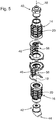
- the return element 46 preferably comprises a molding section 58 for engaging in folds of the bellows 20 (cf. Figures 5 and 6 ).
- the mold portion 58 is complementary to the outside of the bellows 20 of the suction pads 14 and 16 to be used.
- the return element 46 is formed asymmetrically to the longitudinal axis 18, for example, characterized in that the mold portion 46 only a limited angular sector about the longitudinal axis 18 and laterally offset from the longitudinal axis 18 is arranged. The fact that the mold portion 58 engages in the folds of the bellows 20, the bellows 20 is limited in the engaged areas in its compressibility.
- FIG. 6 is the attachment 12 out FIG. 5 shown in detail.
- a particularly simple structure results from the fact that the mounting assembly 12 substantially from two units (upper unit 60, lower unit 62) is constructed.
- the units 60 and 62 are in particular designed in each case as one-piece structures (eg made of plastic).
- the upper assembly 60 comprises the upper nozzle connection 28, an upper spring member 46a and an upper socket portion 64.
- the lower assembly 62 correspondingly comprises the lower nozzle connection 30, a lower spring member 46b and a lower socket portion 66th
- the upper socket portion 64 and the lower socket portion 66 may be joined together to provide the lip socket 32.
- locking elements 38 are provided in particular on the socket sections 64 and 66, which can latch into one another.
- the attachment assembly 12 is modularly constructed from the upper assembly 60 and the lower assembly 62.
- the upper spring element 46a and the lower spring element 46b each have mold sections 58 of the type described for engaging in folds of a bellows-type suction gripper.
- this embodiment is not mandatory. It is also conceivable that the spring parts 46a, 46b have a different configuration, for example in accordance with one of the other embodiments described above.
- the return element 46 extends from the upper nozzle connection to the lower nozzle connection and thus extends along the entire length of the mechanical actuator 10, fluid lines, compressed air lines or electrical lines can be integrated on or in the return element 46 in an advantageous manner.
- a supply channel 68 may be integrated with a supply connection 70 in the restoring element 46.
- the supply channel 46 can serve, for example, a suction gripping element arranged on the lower end element 42 (cf., for example, FIG FIG. 4 ) with negative pressure supply.
- a sensor element 72 is sketched, which is arranged in the illustrated example on the lower end element 42 and is designed, for example, as a pressure sensor or proximity sensor or force sensor.
- a sensor element 72 is sketched, which is arranged in the illustrated example on the lower end element 42 and is designed, for example, as a pressure sensor or proximity sensor or force sensor.
- Corresponding control lines or supply lines may be guided by the restoring element 46 and / or integrated into the restoring element 46.
- the first suction gripper 14 and the further suction gripper 16 are, as explained, connected to one another by means of the lip socket 32, so that a common bellows interior 74 extends in them.
- the bellows interior 74 can be acted upon by the upper end element 40 with negative pressure, for example.
- the return element 46 extends from the upper nozzle connection 28 to the lower nozzle connection 30 laterally offset from the longitudinal axis 18 and thus acts asymmetrically to the longitudinal axis 18.
- the mechanical actuator 10 can be used as a gripping finger.
- the mechanical contact surface 44 of the lower end member 42 then serves to manipulate an object.
Landscapes
- Engineering & Computer Science (AREA)
- Robotics (AREA)
- Mechanical Engineering (AREA)
- Manipulator (AREA)
Priority Applications (1)
| Application Number | Priority Date | Filing Date | Title |
|---|---|---|---|
| EP18170738.1A EP3563982A1 (fr) | 2018-05-04 | 2018-05-04 | Système de montage destiné au montage sur une pince aspirante élastique déformables et actionneur mécanique |
Applications Claiming Priority (1)
| Application Number | Priority Date | Filing Date | Title |
|---|---|---|---|
| EP18170738.1A EP3563982A1 (fr) | 2018-05-04 | 2018-05-04 | Système de montage destiné au montage sur une pince aspirante élastique déformables et actionneur mécanique |
Publications (1)
| Publication Number | Publication Date |
|---|---|
| EP3563982A1 true EP3563982A1 (fr) | 2019-11-06 |
Family
ID=62152336
Family Applications (1)
| Application Number | Title | Priority Date | Filing Date |
|---|---|---|---|
| EP18170738.1A Withdrawn EP3563982A1 (fr) | 2018-05-04 | 2018-05-04 | Système de montage destiné au montage sur une pince aspirante élastique déformables et actionneur mécanique |
Country Status (1)
| Country | Link |
|---|---|
| EP (1) | EP3563982A1 (fr) |
Cited By (2)
| Publication number | Priority date | Publication date | Assignee | Title |
|---|---|---|---|---|
| CN111113402A (zh) * | 2019-12-27 | 2020-05-08 | 浙江清华柔性电子技术研究院 | 气驱动模块单元、气驱动模块组件及软体机器人 |
| JP2023136282A (ja) * | 2022-03-16 | 2023-09-29 | 地方独立行政法人北海道立総合研究機構 | 把持装置およびその製造方法 |
Citations (5)
| Publication number | Priority date | Publication date | Assignee | Title |
|---|---|---|---|---|
| JPH10249775A (ja) * | 1997-03-11 | 1998-09-22 | Kubota Corp | ロボットハンド用指 |
| WO2012042054A2 (fr) * | 2010-09-30 | 2012-04-05 | Commissariat à l'énergie atomique et aux énergies alternatives | Structure mecatronique integree pour un ensemble cinematique portatif |
| WO2013062463A1 (fr) | 2011-10-25 | 2013-05-02 | Xerex Ab | Garniture pour soufflet à compression/expansion non linéaire dans un outil pneumatique |
| WO2015191585A1 (fr) * | 2014-06-09 | 2015-12-17 | Soft Robotics, Inc. | Actionneurs robotiques souples utilisant des surfaces asymétriques |
| US9492930B2 (en) * | 2013-10-18 | 2016-11-15 | President And Fellows Of Harvard College | Mechanically programmed soft actuators with conforming sleeves |
-
2018
- 2018-05-04 EP EP18170738.1A patent/EP3563982A1/fr not_active Withdrawn
Patent Citations (5)
| Publication number | Priority date | Publication date | Assignee | Title |
|---|---|---|---|---|
| JPH10249775A (ja) * | 1997-03-11 | 1998-09-22 | Kubota Corp | ロボットハンド用指 |
| WO2012042054A2 (fr) * | 2010-09-30 | 2012-04-05 | Commissariat à l'énergie atomique et aux énergies alternatives | Structure mecatronique integree pour un ensemble cinematique portatif |
| WO2013062463A1 (fr) | 2011-10-25 | 2013-05-02 | Xerex Ab | Garniture pour soufflet à compression/expansion non linéaire dans un outil pneumatique |
| US9492930B2 (en) * | 2013-10-18 | 2016-11-15 | President And Fellows Of Harvard College | Mechanically programmed soft actuators with conforming sleeves |
| WO2015191585A1 (fr) * | 2014-06-09 | 2015-12-17 | Soft Robotics, Inc. | Actionneurs robotiques souples utilisant des surfaces asymétriques |
Cited By (2)
| Publication number | Priority date | Publication date | Assignee | Title |
|---|---|---|---|---|
| CN111113402A (zh) * | 2019-12-27 | 2020-05-08 | 浙江清华柔性电子技术研究院 | 气驱动模块单元、气驱动模块组件及软体机器人 |
| JP2023136282A (ja) * | 2022-03-16 | 2023-09-29 | 地方独立行政法人北海道立総合研究機構 | 把持装置およびその製造方法 |
Similar Documents
| Publication | Publication Date | Title |
|---|---|---|
| DE3933590C1 (fr) | ||
| DE10032010C1 (de) | Anschlußarmatur mit elastischem Ring als Anschlag | |
| EP3401619A1 (fr) | Appareil de service climatique pour un système de climatisation de véhicule | |
| DE102008064404B4 (de) | Halteausbildung | |
| DE102007015406B3 (de) | Anschlussvorrichtung für eine Fluidleitung | |
| DE3543717C2 (fr) | ||
| EP2712413B1 (fr) | Dispositif de raccordement permettant de raccorder une conduite de fluides | |
| WO2002042676A1 (fr) | Dispositif de raccord d'une conduite de fluide | |
| EP2139017B1 (fr) | Elément de liaison pour appareils d'installation, en particulier pour commutateurs basse tension | |
| EP1342024B1 (fr) | Dispositif d'etancheification | |
| EP2801453B1 (fr) | Dispositif de compensation | |
| EP3563982A1 (fr) | Système de montage destiné au montage sur une pince aspirante élastique déformables et actionneur mécanique | |
| EP4091218B1 (fr) | Pièce de raccordement pour un système de raccordement par enfichage | |
| DE102008056662B4 (de) | Segmentkörper und Abstreifer für einen Fördergurtabstreifer | |
| DE20309196U1 (de) | Schwenkvorrichtung und Schwenksystem | |
| DE102021106667A1 (de) | Greifvorrichtung | |
| EP2252752A2 (fr) | Dispositif permettant de réaliser une connexion électrique sèche d'une serrure de véhicule automobile | |
| EP3943761A1 (fr) | Agencement de fixation | |
| EP3189263B1 (fr) | Dispositif de raccordement pour une conduite de fluide | |
| DE10304514B4 (de) | Fixierteil für eine Schlauchschelle | |
| WO1987005083A1 (fr) | Attache a tete spherique pour cables bowden | |
| EP2918354A1 (fr) | Presse destinée à comprimer axialement des pièces à usiner | |
| EP2734765B1 (fr) | Étrier de brides | |
| DE202020106418U1 (de) | Aufhängungsvorrichtung für die Aufhängung von Werkzeugen von Manipulatoren | |
| DE102005056826A1 (de) | Schlauchanschluss |
Legal Events
| Date | Code | Title | Description |
|---|---|---|---|
| PUAI | Public reference made under article 153(3) epc to a published international application that has entered the european phase |
Free format text: ORIGINAL CODE: 0009012 |
|
| AK | Designated contracting states |
Kind code of ref document: A1 Designated state(s): AL AT BE BG CH CY CZ DE DK EE ES FI FR GB GR HR HU IE IS IT LI LT LU LV MC MK MT NL NO PL PT RO RS SE SI SK SM TR |
|
| AX | Request for extension of the european patent |
Extension state: BA ME |
|
| RIN1 | Information on inventor provided before grant (corrected) |
Inventor name: SCHITTENHELM, FLORIAN Inventor name: KUOLT, HARALD Inventor name: SCHAAF, WALTER |
|
| STAA | Information on the status of an ep patent application or granted ep patent |
Free format text: STATUS: THE APPLICATION IS DEEMED TO BE WITHDRAWN |
|
| 18D | Application deemed to be withdrawn |
Effective date: 20200603 |