EP3563996A1 - Verbesserungen an oder im zusammenhang mit haarschneidemaschinen - Google Patents
Verbesserungen an oder im zusammenhang mit haarschneidemaschinen Download PDFInfo
- Publication number
- EP3563996A1 EP3563996A1 EP19170747.0A EP19170747A EP3563996A1 EP 3563996 A1 EP3563996 A1 EP 3563996A1 EP 19170747 A EP19170747 A EP 19170747A EP 3563996 A1 EP3563996 A1 EP 3563996A1
- Authority
- EP
- European Patent Office
- Prior art keywords
- clipper
- switch
- operating
- electrically operable
- reset
- Prior art date
- Legal status (The legal status is an assumption and is not a legal conclusion. Google has not performed a legal analysis and makes no representation as to the accuracy of the status listed.)
- Granted
Links
Images


Classifications
-
- B—PERFORMING OPERATIONS; TRANSPORTING
- B26—HAND CUTTING TOOLS; CUTTING; SEVERING
- B26B—HAND-HELD CUTTING TOOLS NOT OTHERWISE PROVIDED FOR
- B26B19/00—Clippers or shavers operating with a plurality of cutting edges, e.g. hair clippers, dry shavers
- B26B19/02—Clippers or shavers operating with a plurality of cutting edges, e.g. hair clippers, dry shavers of the reciprocating-cutter type
- B26B19/04—Cutting heads therefor; Cutters therefor; Securing equipment thereof
- B26B19/046—Cutters being movable in the cutting head
-
- B—PERFORMING OPERATIONS; TRANSPORTING
- B26—HAND CUTTING TOOLS; CUTTING; SEVERING
- B26B—HAND-HELD CUTTING TOOLS NOT OTHERWISE PROVIDED FOR
- B26B19/00—Clippers or shavers operating with a plurality of cutting edges, e.g. hair clippers, dry shavers
- B26B19/24—Clippers or shavers operating with a plurality of cutting edges, e.g. hair clippers, dry shavers specially adapted for shearing animals, e.g. sheep
-
- B—PERFORMING OPERATIONS; TRANSPORTING
- B26—HAND CUTTING TOOLS; CUTTING; SEVERING
- B26B—HAND-HELD CUTTING TOOLS NOT OTHERWISE PROVIDED FOR
- B26B19/00—Clippers or shavers operating with a plurality of cutting edges, e.g. hair clippers, dry shavers
- B26B19/38—Details of, or accessories for, hair clippers, or dry shavers, e.g. housings, casings, grips, guards
- B26B19/3806—Accessories
-
- B—PERFORMING OPERATIONS; TRANSPORTING
- B26—HAND CUTTING TOOLS; CUTTING; SEVERING
- B26B—HAND-HELD CUTTING TOOLS NOT OTHERWISE PROVIDED FOR
- B26B19/00—Clippers or shavers operating with a plurality of cutting edges, e.g. hair clippers, dry shavers
- B26B19/38—Details of, or accessories for, hair clippers, or dry shavers, e.g. housings, casings, grips, guards
- B26B19/3853—Housing or handle
-
- B—PERFORMING OPERATIONS; TRANSPORTING
- B26—HAND CUTTING TOOLS; CUTTING; SEVERING
- B26B—HAND-HELD CUTTING TOOLS NOT OTHERWISE PROVIDED FOR
- B26B19/00—Clippers or shavers operating with a plurality of cutting edges, e.g. hair clippers, dry shavers
- B26B19/38—Details of, or accessories for, hair clippers, or dry shavers, e.g. housings, casings, grips, guards
- B26B19/3873—Electric features; Charging; Computing devices
-
- B—PERFORMING OPERATIONS; TRANSPORTING
- B26—HAND CUTTING TOOLS; CUTTING; SEVERING
- B26B—HAND-HELD CUTTING TOOLS NOT OTHERWISE PROVIDED FOR
- B26B19/00—Clippers or shavers operating with a plurality of cutting edges, e.g. hair clippers, dry shavers
- B26B19/38—Details of, or accessories for, hair clippers, or dry shavers, e.g. housings, casings, grips, guards
- B26B19/3886—Actuating members, e.g. switches or control knobs
-
- B—PERFORMING OPERATIONS; TRANSPORTING
- B26—HAND CUTTING TOOLS; CUTTING; SEVERING
- B26B—HAND-HELD CUTTING TOOLS NOT OTHERWISE PROVIDED FOR
- B26B19/00—Clippers or shavers operating with a plurality of cutting edges, e.g. hair clippers, dry shavers
- B26B19/38—Details of, or accessories for, hair clippers, or dry shavers, e.g. housings, casings, grips, guards
- B26B19/42—Details of, or accessories for, hair clippers, or dry shavers, e.g. housings, casings, grips, guards providing for straightening the hair to be cut, e.g. by means of bristles; providing for tensioning the skin, e.g. by means of rollers, ledges
Definitions
- the present invention relates to an electrically operable clipper and more particularly to an electrically operable animal hair clipper.
- Electrically operable clippers may be used to cut hair from the coats of animals.
- Such clippers typically have a handle by which a user is able to grip the clipper, a fixed comb and a movable clipper blade.
- the clipper blade is movable across the comb in a reciprocating manner by an electric motor provided within the handle.
- a transmission arrangement is provided between the output shaft of the motor and the clipper blade in order to convert the rotary motion of the output shaft to the aforementioned reciprocating motion of the clipper blade.
- an electrically operable clipper having a body portion and a head portion, wherein the head portion includes a movable cutter and a fixed comb, the clipper including an internally located electric motor operable to move the movable cutter, wherein the clipper includes an operating switch movable between an off position, an operating positon and a reset position, wherein the reset position operates a motor reset module of the clipper.
- the present invention thus utilises a single switch to both operate the electric motor and to reset the electric motor in the event that a motor cut-out event occurs.
- the present invention thus removes the need for a separate reset switch or button to be provided on the clipper.
- Movement of the operating switch from the off position to the operating position may require movement of the switch in a first direction, and movement of the operating switch from the off position to the reset positon may require movement of the switch in a second direction.
- the first direction may be opposite to the second direction.
- the switch may be biased from the reset position to the off position. This ensures that once a reset operation has been made, then the switch returns to a position ready for the next operation of the clipper.
- the switch may be movable to a further operating position, wherein the operating position corresponds to a first operating speed of the electric motor and the further operating position may correspond to a second operating speed of the electric motor.
- the operating switch may include an internal member and an external member joined to the internal member, where in the internal member is joined to the external member through a slot of the body portion.
- the internal and external members may, for example, be clipped together, joined by adhesive or connected by one or more mechanical fasteners.
- the internal member may include a pair of resilient arms which co-operate with opposed ramp formations of the body portion.
- the co-operation of the arms with the ramp formations defines a detent mechanism of the operating switch.
- the opposed ramp formations each comprise a plurality of inclined surfaces defining a plurality of peaks and troughs.
- the off position and the or each operating position of the switch are defined by opposing troughs of the opposed ramp formations.
- the resilient arms are compressed between facing inclined surfaces of the opposed ramp formations.
- the internal member of the switch may include an abutment surface which contacts the motor reset module when the switch is in the reset position. The abutment surface may be located between the resilient arms.
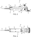
- the clipper 10 is configured for the cutting of the hair of animals, for example bovine and ovine hair.
- the clipper 10 comprises a body portion 12 and head portion 14.
- the body portion 12 is intended to be gripped by the hand of a user of the clipper 10 and is provided with a slidable switch 16.
- the switch 16 is positioned and configured such that it can be manipulated by the thumb of a user while gripping the clipper 10 in one hand.
- the head portion 14 of the clipper 10 includes a fixed comb 18 and a movable cutter 20.
- the cutter 20 is movable in an arc across the comb 18 in a reciprocating manner by a drive mechanism of the clipper 10.
- the head portion 14 further includes a tension nut 22 which can be manipulated by a user of the clipper 10 to vary the contact pressure between the cutter 20 and the comb 18.
- the cutter 20 may be configured to move linearly over the comb 18 in a side to side reciprocating manner.
- the clipper 10 is electrically powered and is provided with a power cable 24 which extends from an end of the body portion 12 which is distal to the head portion 14, hereinafter referred to as the distal end 13 of the body portion 12.
- a cable support 26 which prevents kinking of the cable 24 is provided at the location where the cable 24 enters the body portion.
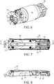
- the body portion 12 of the clipper 10 includes upper and lower casing halves 28, 30 which are, in use, connected to one another.
- the casing halves 28,30 may be formed from plastic, for example by injection moulding.
- the upper casing half 28 includes the slidable switch 16 and a plurality of inlet apertures 32.
- the inlet apertures 32 are provided at the end of the upper casing half 28 which is distal to the head portion.
- the upper casing half 28 is provided with eight inlet apertures 32. It will be appreciated that a greater or lesser number of inlet apertures 32 may be provided.
- the inlet apertures 32 are covered by a mesh panel located to the interior of the body portion 12 which acts to prevent the ingress of dust and debris such as animal hair clippings.
- the head portion 14 is further provided with outlet apertures 34a,34b.
- a first outlet aperture 24a is provided to the underside of the clipper 10, which is to say the side of the clipper 10 opposite to that which has the inlet apertures 32.
- the outlet aperture 34 is semi-circular. It will be understood that the outlet aperture 34 may have alternative shapes.
- Two smaller outlet apertures 34b are provided on opposing sides of the clipper 10 at the interface of the body portion 12 to the head portion 14.
- the body portion 12 includes a longitudinally aligned electric motor 36.
- the electric motor 36 includes an output shaft (not shown) which extends into the head portion 14 and, in use, operates the aforementioned drive mechanism to move the cutter 20 across the comb 18.
- the motor 36 is provided at opposite ends with a fan member 38,40.
- Each fan member 38,40 is connected to a shaft of the electric motor such that each fan member 38, 40 is rotated when the motor 36 is operated.
- Each fan member 38,40 is provided with a plurality of blades.
- the fan member 38 located at the end of the motor 36 which is distal to the head portion 14 (hereinafter referred to as the distal fan member 38) is configured as an axial flow fan.
- rotation of the distal fan member 38 causes air to be drawn into the body portion 12 through the inlet apertures 32 as indicated by arrow 42. Air which has been drawn into the body portion 12 in the manner described is then urged by the distal fan member 38 over and through the electric motor 36 in the direction of the head portion 14.
- the distal fan member 38 is offset longitudinally within the body portion 12 with respect to the inlet apertures 32.
- the fan member 40 located at the end of the motor 36 which is proximal to the head portion 14 (hereinafter referred to as the proximal fan member 40) is configured as a radial flow fan.
- rotation of the proximal fan member 40 causes air to be ejected from the interior of the body portion 12 through the outlet aperture 34 provided in the head portion 14 as indicated by arrow 44.
- the outlet aperture 34 is aligned radially with respect to the proximal fan member 40.
- the clipper 10 is provided with a slidable switch 16.
- the slidable switch 16 is operable to activate and deactivate the electric motor 36.
- the switch is movable in a longitudinal direction between an off position, a first operating position and a second operating position.
- the first and second operating positions correspond to first and second operating speeds of the electric motor, where the second operating speed is greater than the first operating speed.
- the switch 36 is also longitudinally movable to a reset position where an internal reset module 46 of the clipper 10 is operated.
- the reset module 46 is provided to re-enable operation of the motor 36 after a motor cut-out event has occurred.
- the clipper 10 is provided with a motor cut-out mechanism to prevent damage to the motor 36 by, for example, a power surge, overheating, jamming of the comb 18 and cutter 20 or other such event outside of the normal operating parameters of the clipper 10.
- FIGs 7 to 17 illustrate the configuration of the slidable switch 16 and reset module 46.
- the switch 16 includes an external member 48 and an internal member 50.
- the external member 48 as noted above, is configured such that it can be manipulated by the thumb of a user while gripping the clipper 10 in one hand.
- the external member 48 is provided with a plurality of ridges 52 which are arranged substantially transverse to the longitudinal form of the body portion 12.
- the external member 48 is formed from plastic, for example by injection moulding.
- the external member 48 is provided with a connector portions 52 which connect the external member 48 to the internal member 50.
- the connector portions 53 comprise arms which connect to a complementarily shaped location on the internal member 50.
- the internal member 50 has a length that is greater than the length of the external member 48.
- the internal member 50 has a first end 54 to which the external member 48 is attached, and a second end 56 having a spaced pair of arms 58 and an abutment surface 60 positioned between the arms 58.
- the abutment surface 60 in use, is configured to abut an actuation member 62 of a reset module 46 as will be described in greater detail below.
- the internal member 50 is further provided with a guide surface 64 which, in use, lies against a surface 66 of the reset module 46.
- the internal member 50 is formed from plastic, for example by injection moulding.
- the arms 58 of the internal member 50 are provided with rounded ends 68 which, in use, interact with opposed ramp formations 70 of the upper casing half 28 to provide a detent mechanism of the switch 16.
- the external member 48 of the switch 16 is connected to the internal member 50 through a slot 72 of the upper casing half 28, and the first end 54 of the internal member 50 is received in a longitudinal guideway 74 of the upper casing half 28.
- the internal member 50 extends along the inner surface of the upper casing half 28 in the direction of the inlet apertures 32 thereof.
- the opposed ramp formations 70 of the upper casing half 28 are provided on the inner surface of the upper casing half adjacent the inlet apertures 32.
- the reset module 46 is located below the inlet apertures 32.
- the ramp formations 70 each comprise a plurality of inclined surfaces which define an alternating series of peaks and troughs.
- the opposed ramp formations 70 and arms 58 of internal member 50 define the off position of the switch 16 ( figure 9 ), the first operating position of the switch 16 ( figure 10 ) and the second operating position of the switch 16 ( figure 11 ). These positions of the switch 16 are defined by opposing troughs of the ramp portions 70 into which the rounded ends 68 of the arms 58 are urged by the inherent resilience of the arms 58. Movement of the switch 16 between the off position and the first operating position, and the first operating position and the second operating position, causes the arms 58 to be deflected towards one another by opposed peaks of the ramp formations 70.
- the abutment surface 60 of the internal member 50 is spaced from the actuation member 62 of the reset module 46.
- the user is required to move the switch 16 to a reset position such that the abutment surface 60 contacts and thereafter moves the actuation member 62 of the reset module 46. So as to prevent inadvertent operation the reset module 46, the reset position of the switch 16 is in the opposite direction from the off position to the first and second operating positions.
- the detent mechanism of the switch 16 is configured such that the switch 16 is biased towards the off position from the reset position.
- Figure 14 shows the position of the internal member 50 in the reset position.
- the abutment surface 60 is shown contacting the actuation member 62 of the reset module 46, while the arms 58 are shown compressed by the opposed ramp formations 70. Compression of the arms 58 in this manner provides a restorative force which moves the switch 16 to the off position once the user releases the switch 16.
Landscapes
- Life Sciences & Earth Sciences (AREA)
- Forests & Forestry (AREA)
- Engineering & Computer Science (AREA)
- Mechanical Engineering (AREA)
- Animal Behavior & Ethology (AREA)
- Animal Husbandry (AREA)
- Dry Shavers And Clippers (AREA)
- Scissors And Nippers (AREA)
- Slide Switches (AREA)
Applications Claiming Priority (1)
| Application Number | Priority Date | Filing Date | Title |
|---|---|---|---|
| GB1807005.2A GB2573289B (en) | 2018-04-30 | 2018-04-30 | Improvement in or Relating to Clippers |
Publications (3)
| Publication Number | Publication Date |
|---|---|
| EP3563996A1 true EP3563996A1 (de) | 2019-11-06 |
| EP3563996B1 EP3563996B1 (de) | 2023-07-05 |
| EP3563996C0 EP3563996C0 (de) | 2023-07-05 |
Family
ID=62495107
Family Applications (1)
| Application Number | Title | Priority Date | Filing Date |
|---|---|---|---|
| EP19170747.0A Active EP3563996B1 (de) | 2018-04-30 | 2019-04-24 | Verbesserungen an oder im zusammenhang mit haarschneidemaschinen |
Country Status (4)
| Country | Link |
|---|---|
| US (1) | US10981285B2 (de) |
| EP (1) | EP3563996B1 (de) |
| CN (1) | CN110405815A (de) |
| GB (1) | GB2573289B (de) |
Families Citing this family (3)
| Publication number | Priority date | Publication date | Assignee | Title |
|---|---|---|---|---|
| GB2573289B (en) * | 2018-04-30 | 2021-06-30 | Lister Shearing Equip Ltd | Improvement in or Relating to Clippers |
| USD898289S1 (en) * | 2018-05-02 | 2020-10-06 | Lister Shearing Equipment Limited | Hair clipper |
| USD942685S1 (en) | 2019-03-14 | 2022-02-01 | Lister Shearing Equipment Limited | Hair clipper |
Citations (3)
| Publication number | Priority date | Publication date | Assignee | Title |
|---|---|---|---|---|
| DE2436276A1 (de) * | 1974-07-27 | 1976-02-12 | Spiegel Bernt Prof Dr | Motorisch betriebener trockenrasierapparat |
| EP0147134A2 (de) * | 1983-12-15 | 1985-07-03 | Kyushu Hitachi Maxell, Ltd. | Elektrische Haarschneidemaschine |
| US5050304A (en) * | 1988-12-15 | 1991-09-24 | Matsushita Electric Works, Ltd. | Hair clipper |
Family Cites Families (12)
| Publication number | Priority date | Publication date | Assignee | Title |
|---|---|---|---|---|
| US3215894A (en) * | 1961-07-17 | 1965-11-02 | Haussermann Erich | Electric razors with protective voltage-sensing means |
| NL8004115A (nl) * | 1980-07-17 | 1982-02-16 | Philips Nv | Elektrisch apparaat, bijvoorbeeld een scheerapparaat, voorzien van een telmachinisme. |
| DE3727921C1 (de) * | 1987-08-21 | 1989-01-05 | Braun Ag | Schalter zur Ein- und Ausschaltung eines elektrisch betreibbaren Antriebsteiles eines Geraetes |
| DE3729257A1 (de) * | 1987-09-02 | 1989-03-23 | Braun Ag | Trockenrasierapparat mit einem kurzhaarschneidsystem und einem verschiebbaren langhaarschneidsystem |
| JPH01198588A (ja) * | 1988-12-23 | 1989-08-10 | Kyushu Hitachi Maxell Ltd | 電気かみそり |
| CN2266485Y (zh) * | 1996-07-24 | 1997-11-05 | 森焱电子有限公司 | 电动剪发器 |
| DE19633037C1 (de) * | 1996-08-16 | 1997-05-28 | Braun Ag | Trockenrasierapparat mit Schutzkappe |
| US20030131480A1 (en) * | 2002-01-11 | 2003-07-17 | Conair Corporation | Hair clipper with turbo-cutting mode |
| CN2860771Y (zh) * | 2005-05-30 | 2007-01-24 | 易耀实业有限公司 | 设有位置记忆可调辅助梳的电动剪发器 |
| CN204585270U (zh) * | 2014-12-04 | 2015-08-26 | 上海雷瓦电器有限公司 | 限位梳及应用其的理发器 |
| US20190321994A1 (en) * | 2018-04-21 | 2019-10-24 | Naftoli Jacobowitz | Pet clippers having halo-illumination lighting |
| GB2573289B (en) * | 2018-04-30 | 2021-06-30 | Lister Shearing Equip Ltd | Improvement in or Relating to Clippers |
-
2018
- 2018-04-30 GB GB1807005.2A patent/GB2573289B/en active Active
-
2019
- 2019-04-24 EP EP19170747.0A patent/EP3563996B1/de active Active
- 2019-04-25 US US16/394,826 patent/US10981285B2/en active Active
- 2019-04-28 CN CN201910359099.7A patent/CN110405815A/zh active Pending
Patent Citations (3)
| Publication number | Priority date | Publication date | Assignee | Title |
|---|---|---|---|---|
| DE2436276A1 (de) * | 1974-07-27 | 1976-02-12 | Spiegel Bernt Prof Dr | Motorisch betriebener trockenrasierapparat |
| EP0147134A2 (de) * | 1983-12-15 | 1985-07-03 | Kyushu Hitachi Maxell, Ltd. | Elektrische Haarschneidemaschine |
| US5050304A (en) * | 1988-12-15 | 1991-09-24 | Matsushita Electric Works, Ltd. | Hair clipper |
Also Published As
| Publication number | Publication date |
|---|---|
| EP3563996B1 (de) | 2023-07-05 |
| GB2573289B (en) | 2021-06-30 |
| GB201807005D0 (en) | 2018-06-13 |
| US20190329432A1 (en) | 2019-10-31 |
| CN110405815A (zh) | 2019-11-05 |
| US10981285B2 (en) | 2021-04-20 |
| EP3563996C0 (de) | 2023-07-05 |
| GB2573289A (en) | 2019-11-06 |
Similar Documents
| Publication | Publication Date | Title |
|---|---|---|
| US10981285B2 (en) | Hair clipper operating switch with reset function | |
| CN101432104B (zh) | 切割设备和毛发切割装置 | |
| EP3907046B1 (de) | Elektrischer bartschneider | |
| EP3261810B1 (de) | Stationäre klinge, klingensatz und haarschneidegerät | |
| EP1894685B1 (de) | Haarschneidemaschine | |
| CN101790442B (zh) | 毛发修剪器 | |
| US20110126412A1 (en) | Hair Removal Apparatus | |
| EP3563995A1 (de) | Verbesserungen an oder im zusammenhang mit haarschneidemaschinen | |
| US7114257B1 (en) | Multi purpose machine | |
| EP1616500A1 (de) | Haarföhn mit ergonomischer Schalteranordnung | |
| US20020162226A1 (en) | Hair clipper with pivoting clipper head assembly | |
| WO2016041959A1 (en) | Cutting head and hair cutting appliance | |
| WO2005063077A1 (en) | A shearing device including ridges | |
| CN113263525A (zh) | 除毛装置的刀片及具备除毛装置的刀片的除毛装置 | |
| US20050055834A1 (en) | Electric hair trimmer | |
| CN117813002A (zh) | 用于宠物的毛发修剪器和去毛器 | |
| JP7760614B2 (ja) | 安全スイッチを有する手持ち式電動工具 | |
| CN102189533A (zh) | 动力工具及其开关装置 | |
| KR200474718Y1 (ko) | 애완동물 털 커팅장치 | |
| JPH08126434A (ja) | 手持ち式電動作業機 | |
| CN118716037A (zh) | 绿篱修剪机 | |
| US11857054B2 (en) | Cutting comb | |
| US3711944A (en) | Electric dry shaver | |
| US20260061643A1 (en) | Modular Electric Hair Cutting System Attachments | |
| WO2026046967A1 (en) | Controlled and practically play-free movement of a head member in an assembly for use in a handheld personal care appliance |
Legal Events
| Date | Code | Title | Description |
|---|---|---|---|
| PUAI | Public reference made under article 153(3) epc to a published international application that has entered the european phase |
Free format text: ORIGINAL CODE: 0009012 |
|
| STAA | Information on the status of an ep patent application or granted ep patent |
Free format text: STATUS: THE APPLICATION HAS BEEN PUBLISHED |
|
| AK | Designated contracting states |
Kind code of ref document: A1 Designated state(s): AL AT BE BG CH CY CZ DE DK EE ES FI FR GB GR HR HU IE IS IT LI LT LU LV MC MK MT NL NO PL PT RO RS SE SI SK SM TR |
|
| AX | Request for extension of the european patent |
Extension state: BA ME |
|
| STAA | Information on the status of an ep patent application or granted ep patent |
Free format text: STATUS: REQUEST FOR EXAMINATION WAS MADE |
|
| 17P | Request for examination filed |
Effective date: 20200506 |
|
| RBV | Designated contracting states (corrected) |
Designated state(s): AL AT BE BG CH CY CZ DE DK EE ES FI FR GB GR HR HU IE IS IT LI LT LU LV MC MK MT NL NO PL PT RO RS SE SI SK SM TR |
|
| RIC1 | Information provided on ipc code assigned before grant |
Ipc: B26B 19/38 20060101AFI20220609BHEP |
|
| GRAP | Despatch of communication of intention to grant a patent |
Free format text: ORIGINAL CODE: EPIDOSNIGR1 |
|
| STAA | Information on the status of an ep patent application or granted ep patent |
Free format text: STATUS: GRANT OF PATENT IS INTENDED |
|
| INTG | Intention to grant announced |
Effective date: 20220908 |
|
| GRAJ | Information related to disapproval of communication of intention to grant by the applicant or resumption of examination proceedings by the epo deleted |
Free format text: ORIGINAL CODE: EPIDOSDIGR1 |
|
| STAA | Information on the status of an ep patent application or granted ep patent |
Free format text: STATUS: REQUEST FOR EXAMINATION WAS MADE |
|
| INTC | Intention to grant announced (deleted) | ||
| GRAP | Despatch of communication of intention to grant a patent |
Free format text: ORIGINAL CODE: EPIDOSNIGR1 |
|
| STAA | Information on the status of an ep patent application or granted ep patent |
Free format text: STATUS: GRANT OF PATENT IS INTENDED |
|
| INTG | Intention to grant announced |
Effective date: 20230228 |
|
| GRAS | Grant fee paid |
Free format text: ORIGINAL CODE: EPIDOSNIGR3 |
|
| GRAA | (expected) grant |
Free format text: ORIGINAL CODE: 0009210 |
|
| STAA | Information on the status of an ep patent application or granted ep patent |
Free format text: STATUS: THE PATENT HAS BEEN GRANTED |
|
| AK | Designated contracting states |
Kind code of ref document: B1 Designated state(s): AL AT BE BG CH CY CZ DE DK EE ES FI FR GB GR HR HU IE IS IT LI LT LU LV MC MK MT NL NO PL PT RO RS SE SI SK SM TR |
|
| REG | Reference to a national code |
Ref country code: CH Ref legal event code: EP |
|
| REG | Reference to a national code |
Ref country code: AT Ref legal event code: REF Ref document number: 1584416 Country of ref document: AT Kind code of ref document: T Effective date: 20230715 |
|
| REG | Reference to a national code |
Ref country code: DE Ref legal event code: R096 Ref document number: 602019031974 Country of ref document: DE |
|
| REG | Reference to a national code |
Ref country code: IE Ref legal event code: FG4D |
|
| U01 | Request for unitary effect filed |
Effective date: 20230802 |
|
| U07 | Unitary effect registered |
Designated state(s): AT BE BG DE DK EE FI FR IT LT LU LV MT NL PT SE SI Effective date: 20230808 |
|
| REG | Reference to a national code |
Ref country code: LT Ref legal event code: MG9D |
|
| PG25 | Lapsed in a contracting state [announced via postgrant information from national office to epo] |
Ref country code: GR Free format text: LAPSE BECAUSE OF FAILURE TO SUBMIT A TRANSLATION OF THE DESCRIPTION OR TO PAY THE FEE WITHIN THE PRESCRIBED TIME-LIMIT Effective date: 20231006 |
|
| PG25 | Lapsed in a contracting state [announced via postgrant information from national office to epo] |
Ref country code: ES Free format text: LAPSE BECAUSE OF FAILURE TO SUBMIT A TRANSLATION OF THE DESCRIPTION OR TO PAY THE FEE WITHIN THE PRESCRIBED TIME-LIMIT Effective date: 20230705 |
|
| PG25 | Lapsed in a contracting state [announced via postgrant information from national office to epo] |
Ref country code: IS Free format text: LAPSE BECAUSE OF FAILURE TO SUBMIT A TRANSLATION OF THE DESCRIPTION OR TO PAY THE FEE WITHIN THE PRESCRIBED TIME-LIMIT Effective date: 20231105 |
|
| PG25 | Lapsed in a contracting state [announced via postgrant information from national office to epo] |
Ref country code: RS Free format text: LAPSE BECAUSE OF FAILURE TO SUBMIT A TRANSLATION OF THE DESCRIPTION OR TO PAY THE FEE WITHIN THE PRESCRIBED TIME-LIMIT Effective date: 20230705 Ref country code: NO Free format text: LAPSE BECAUSE OF FAILURE TO SUBMIT A TRANSLATION OF THE DESCRIPTION OR TO PAY THE FEE WITHIN THE PRESCRIBED TIME-LIMIT Effective date: 20231005 Ref country code: IS Free format text: LAPSE BECAUSE OF FAILURE TO SUBMIT A TRANSLATION OF THE DESCRIPTION OR TO PAY THE FEE WITHIN THE PRESCRIBED TIME-LIMIT Effective date: 20231105 Ref country code: HR Free format text: LAPSE BECAUSE OF FAILURE TO SUBMIT A TRANSLATION OF THE DESCRIPTION OR TO PAY THE FEE WITHIN THE PRESCRIBED TIME-LIMIT Effective date: 20230705 Ref country code: GR Free format text: LAPSE BECAUSE OF FAILURE TO SUBMIT A TRANSLATION OF THE DESCRIPTION OR TO PAY THE FEE WITHIN THE PRESCRIBED TIME-LIMIT Effective date: 20231006 Ref country code: ES Free format text: LAPSE BECAUSE OF FAILURE TO SUBMIT A TRANSLATION OF THE DESCRIPTION OR TO PAY THE FEE WITHIN THE PRESCRIBED TIME-LIMIT Effective date: 20230705 |
|
| PG25 | Lapsed in a contracting state [announced via postgrant information from national office to epo] |
Ref country code: PL Free format text: LAPSE BECAUSE OF FAILURE TO SUBMIT A TRANSLATION OF THE DESCRIPTION OR TO PAY THE FEE WITHIN THE PRESCRIBED TIME-LIMIT Effective date: 20230705 |
|
| REG | Reference to a national code |
Ref country code: DE Ref legal event code: R097 Ref document number: 602019031974 Country of ref document: DE |
|
| PG25 | Lapsed in a contracting state [announced via postgrant information from national office to epo] |
Ref country code: SM Free format text: LAPSE BECAUSE OF FAILURE TO SUBMIT A TRANSLATION OF THE DESCRIPTION OR TO PAY THE FEE WITHIN THE PRESCRIBED TIME-LIMIT Effective date: 20230705 Ref country code: RO Free format text: LAPSE BECAUSE OF FAILURE TO SUBMIT A TRANSLATION OF THE DESCRIPTION OR TO PAY THE FEE WITHIN THE PRESCRIBED TIME-LIMIT Effective date: 20230705 Ref country code: CZ Free format text: LAPSE BECAUSE OF FAILURE TO SUBMIT A TRANSLATION OF THE DESCRIPTION OR TO PAY THE FEE WITHIN THE PRESCRIBED TIME-LIMIT Effective date: 20230705 Ref country code: SK Free format text: LAPSE BECAUSE OF FAILURE TO SUBMIT A TRANSLATION OF THE DESCRIPTION OR TO PAY THE FEE WITHIN THE PRESCRIBED TIME-LIMIT Effective date: 20230705 |
|
| PLBE | No opposition filed within time limit |
Free format text: ORIGINAL CODE: 0009261 |
|
| STAA | Information on the status of an ep patent application or granted ep patent |
Free format text: STATUS: NO OPPOSITION FILED WITHIN TIME LIMIT |
|
| U20 | Renewal fee for the european patent with unitary effect paid |
Year of fee payment: 6 Effective date: 20240417 |
|
| 26N | No opposition filed |
Effective date: 20240408 |
|
| PG25 | Lapsed in a contracting state [announced via postgrant information from national office to epo] |
Ref country code: MC Free format text: LAPSE BECAUSE OF FAILURE TO SUBMIT A TRANSLATION OF THE DESCRIPTION OR TO PAY THE FEE WITHIN THE PRESCRIBED TIME-LIMIT Effective date: 20230705 |
|
| PG25 | Lapsed in a contracting state [announced via postgrant information from national office to epo] |
Ref country code: MC Free format text: LAPSE BECAUSE OF FAILURE TO SUBMIT A TRANSLATION OF THE DESCRIPTION OR TO PAY THE FEE WITHIN THE PRESCRIBED TIME-LIMIT Effective date: 20230705 |
|
| REG | Reference to a national code |
Ref country code: CH Ref legal event code: PL |
|
| GBPC | Gb: european patent ceased through non-payment of renewal fee |
Effective date: 20240424 |
|
| PG25 | Lapsed in a contracting state [announced via postgrant information from national office to epo] |
Ref country code: GB Free format text: LAPSE BECAUSE OF NON-PAYMENT OF DUE FEES Effective date: 20240424 |
|
| PG25 | Lapsed in a contracting state [announced via postgrant information from national office to epo] |
Ref country code: GB Free format text: LAPSE BECAUSE OF NON-PAYMENT OF DUE FEES Effective date: 20240424 Ref country code: CH Free format text: LAPSE BECAUSE OF NON-PAYMENT OF DUE FEES Effective date: 20240430 |
|
| PG25 | Lapsed in a contracting state [announced via postgrant information from national office to epo] |
Ref country code: IE Free format text: LAPSE BECAUSE OF NON-PAYMENT OF DUE FEES Effective date: 20240424 |
|
| U20 | Renewal fee for the european patent with unitary effect paid |
Year of fee payment: 7 Effective date: 20250416 |
|
| PG25 | Lapsed in a contracting state [announced via postgrant information from national office to epo] |
Ref country code: CY Free format text: LAPSE BECAUSE OF FAILURE TO SUBMIT A TRANSLATION OF THE DESCRIPTION OR TO PAY THE FEE WITHIN THE PRESCRIBED TIME-LIMIT; INVALID AB INITIO Effective date: 20190424 |
|
| PG25 | Lapsed in a contracting state [announced via postgrant information from national office to epo] |
Ref country code: HU Free format text: LAPSE BECAUSE OF FAILURE TO SUBMIT A TRANSLATION OF THE DESCRIPTION OR TO PAY THE FEE WITHIN THE PRESCRIBED TIME-LIMIT; INVALID AB INITIO Effective date: 20190424 |